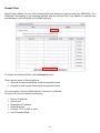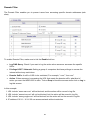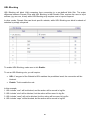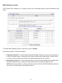
1
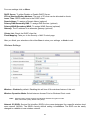
LevelOne
User Manual
WBR-6022
HomeGuard 22 Residential Gateway
Ver. 1.2
Safety
FCC WARNING
This equipment may generate or use radio frequency energy. Changes or modifications to this
equipment may cause harmful interference unless the modifications are expressly approved in the
instruction manual. The user could lose the authority to operate this equipment if an unauthorized
change or modification is made.
This equipment has been tested and found to comply with the limits for a Class B digital device,
pursuant to Part 15 of the FCC Rules. These limits are designed to provide reasonable protection
against harmful interference in a residential installation. This equipment generates, uses, and can
radiate radio frequency energy and, if not installed and used in accordance with the instructions, may
cause harmful interference to radio communications. However, there is no guarantee that
interference will not occur in a particular installation. If this equipment does cause harmful
interference to radio or television reception, which can be determined by turning the equipment off
and on, the user is encouraged to try to correct the interference by one or more of the following
measures:
1) Reorient or relocate the receiving antenna.
2) Increase the separation between the equipment and receiver.
3) Connect the equipment into an outlet on a circuit different from that to which the receiver is
connected.
4) Consult the dealer or an experienced radio/TV technician for help.
CE Declaration of conformity
This equipment complies with the requirements relating to electromagnetic compatibility, EN 55022
class B for ITE, the essential protection requirement of Council Directive 89/336/EEC on the
approximation of the laws of the Member States relating to electromagnetic compatibility.
CE Marking Warning
Hereby, Digital Data Communications, declares that this product (Model-no. WBR-6022) is in
compliance with the essential requirements and other relevant provisions of Directive 1999/5/EC.
The CE-Declaration of Conformity can be downloaded at:
http://www.levelone.eu/support.php
2
General Public License
This product incorporates open source code into the software and therefore falls under the guidelines
governed by the General Public License (GPL) agreement.
Adhering to the GPL requirements, the open source code and open source license for the source
code are available for free download at http://global.level1.com.
If you would like a copy of the GPL or other open source code in this software on a physical CD
medium, LevelOne (Digital Data Communications) offers to mail this CD to you upon request, for a
price of US$9.99 plus the cost of shipping.
3
Table of Content
TABLE OF CONTENT ...............................................................................................................................................................4
1
INTRODUCTION ................................................................................................................................................................5
2
PRODUCT FEATURES ......................................................................................................................................................6
3
PACKAGE CONTENTS & HARDWARE INSTALLATION ........................................................................................7
4
CHECK YOUR NETWORK SETTINGS........................................................................................................................13
5
CONFIGURATION WIZARD .........................................................................................................................................14
5.1 EASY SETUP UTILITY....................................................................................................................................................14
5.2 LOGIN TOOL ....................................................................................................................................................................22
5.3 WEB-BASE CONFIGURATION .....................................................................................................................................22
6
HOMEGUARD SYSTEM SETTING...............................................................................................................................23
6.1 PREPARE THE IP CAMERA AND STORAGE ............................................................................................................23
6.2 HOMEGUARD WEB UI ...................................................................................................................................................24
6.2.1
STATUS ......................................................................................................................................................................25
6.2.2
SEARCH IP CAMERA AND STORAGE................................................................................................................26
6.2.3
REGISTER IP CAMERA AND STORAGE............................................................................................................26
6.2.4
VIEW IP CAMERA ...................................................................................................................................................27
6.2.4.1 VIEW ALL IP CAMERAS........................................................................................................................................27
6.2.4.2 VIEW ONE IP CAMERA .........................................................................................................................................27
6.2.5
RECORD IP CAMERA.............................................................................................................................................28
6.2.5.1 SET RECORD PATH. ...............................................................................................................................................28
6.2.5.2 RECORD IP CAMERA.............................................................................................................................................28
6.2.5.3 SAVE SCREEN SHOT ..............................................................................................................................................28
6.2.5.4 SCHEDULING RECORD .........................................................................................................................................29
6.2.6
CHECK THE RECORD ON FNS-1020 V2 .............................................................................................................29
6.2.7
ADVANCED SETTING.............................................................................................................................................30
6.2.7.1 ACCOUNT MANAGEMENT...................................................................................................................................30
6.2.7.2 ADMINISTRATOR MANAGEMENT ....................................................................................................................30
6.2.7.3 ADD NORMAL USER...............................................................................................................................................30
6.2.7.4 NORMAL USER MANAGEMENT .........................................................................................................................31
6.2.8
EMAIL ALERT..........................................................................................................................................................31
6.2.9
UNREGISTER............................................................................................................................................................31
6.2.10
CHANGE ALIAS DOMAIN NAME ........................................................................................................................32
7
ROUTER SETTING ..........................................................................................................................................................33
8
ADVANCED SETUP .........................................................................................................................................................35
BASIC SETTING .................................................................................................................................................................................... 36
FORWARDING RULES ........................................................................................................................................................................... 52
SECURITY SETTINGS ............................................................................................................................................................................. 56
ADVANCED SETTINGS .......................................................................................................................................................................... 64
TOOLBOX ............................................................................................................................................................................................. 74
TECHNICAL SPECIFICATIONS ...........................................................................................................................................88
Default Settings
IP Address
Username
Password
Wireless Mode
Wireless SSID
Wireless Security
192.168.0.1
admin
password
Enable
LevelOne
None
4
1 Introduction
Congratulations on your purchase of LevelOne WBR-6022 HomeGuard 22 Residential Gateway. This
product is specifically designed for Small Office and Home Office needs. It provides a complete
SOHO solution for Internet surfing, and is easy to configure and operate even for non-technical users.
Instructions for installing and configuring this product can be found in this manual. Before you install
and use this product, please read the manual carefully for fully exploiting the functions of this product.
User Manual Overview
Introduction Describes the HomeGuard 22 Residential Gateway.
Unpacking and Setup Helps user to get started with the basic installation of the router.
Hardware Installation Describes the LED indicators router.
Configuration Describes the functionalities and its settings.
Technical Specifications Lists the technical (general, physical and environmental)
specifications of the router.
5
2 Product Features
This chapter provides the package contents and setup information for the HomeGuard 22 Residential
Gateway.
Features
HomeGuard functions
Camera View
Get supporting IP Cameras and after pairing with them, this device could show the camera screen on web UI.
Camera Record
Get supporting IP Cameras and storage devices, after pairing with them, this device could record the video data of
camera into storage HDD. It also supports schedule and manually recording.
Level1DNS.net
The WBR-6022 had build-in a DDNS account, user can easily to remote access via internet, the default DDNS
account also allow user to modify by level1dns.net (Level1 Service)
Router Basic functions
Auto-sensing Ethernet Switch
Equipped with a 4-port auto-sensing Ethernet switch.
WAN type supported
The router supports some WAN types, Static, Dynamic, PPPoE , PPTP ,L2TP, Dynamic IP with Road Runner.
Firewall
All unwanted packets from outside intruders are blocked to protect your Intranet.
DHCP server supported
All of the networked computers can retrieve TCP/IP settings automatically from this product.
Web-based configuring
Configurable through any networked computer’s web browser using Netscape or Internet Explorer.
Virtual Server supported
Enable you to expose WWW, FTP and other services on your LAN to be accessible to Internet users.
User-Definable Application Sensing Tunnel
User can define the attributes to support the special applications requiring multiple connections, like Internet
gaming, video conferencing, Internet telephony and so on, then this product can sense the application type and
open multi-port tunnel for it.
DMZ Host supported
Lets a networked computer be fully exposed to the Internet; this function is used when special application
sensing tunnel feature is insufficient to allow an application to function correctly.
Statistics of WAN Supported
Enables you to monitor inbound and outbound packets
Wireless functions
High speed for wireless LAN connection
Up to 80Mbps data rate by incorporating Orthogonal Frequency Division Multiplexing (OFDM).
Roaming
Provides seamless roaming within the IEEE 802.11b (11M) and IEEE 802.11g (54M) WLAN infrastructure.
WDS(Wireless Distribution System): It is a system that enables the interconnection of access points wirelessly.
WPS(WiFi Protection Setup):WPS is WiFi Protection Setup which is similar to WCN-NET and offer safe and
easy way in Wireless Connection.
IEEE 802.11b compatible (11M)
Allowing inter-operation among multiple vendors.
IEEE 802.11g compatible (54M)
Allowing inter-operation among multiple vendors.
IEEE 802.11n compatible (300M)
Green functions
Standby mode:
When No Wireless Station is associated with Green Router in several minutes, it will be automatically switched
into Standby mode. Of course, this mode will not influence on end users to roam Internet, such as noon Reset
time 12:00~13:30.
6
Sleep Mode:
When time matches with rule of Schedule, Green Router will detect whether any client or Network flow. If No,
Green Router will be in Sleep mode. Otherwise, it will not go to sleep mode until no data flowing in network.
This mode can save almost 100% energy. (End-user can’t use Internet in Sleep Mode.) Such as
11:00PM~10:00AM for Family or 19:00PM~07:00AM for Office or in Weekend.
Smart Schedule:
When time matches with Schedule rule, for example,11:00PM~08:00AM is in Sleep Mode, Green Router will
detect if Network flow or Wireless Stations at 11:00PM, if no, it will go in Sleep Mode until 8:00AM. If yes,
Green Router will detect until no data flowing and Wireless Stations then go “Sleep Mode”.
Smart Schedule has another feature is when end-user wakes up at 3:00AM,then click On/Sleep button to
awaken Green Router to use Internet until 5:00AM, then Green Router will detect no flow and Wireless
Stations ,then go “Sleep Mode” until 08:00AM.
On/Sleep Button:
End users can wake up Green Router from Sleep Mode via this Button.
※ There is a limit that End-user forces to sleep via this button and has to wake Green Router up by this Button. And
Force to wake up via this button and can Sleep by Schedule.
Security functions
Packet filter supported
Packet Filter allows you to control access to a network by analyzing the incoming and outgoing packets and
letting them pass or halting them based on the IP address of the source and destination.
Domain Filter Supported
Let you prevent users under this device from accessing specific URLs.
URL Blocking Supported
URL Blocking can block hundreds of websites connection by simply a keyword.
VPN Pass-through
The router also supports VPN pass-through.
802.1X supported
When the 802.1X function is enabled, the Wireless user must authenticate to this router first to use the Network
service.
Support WPA-PSK and WPA version 1 and 2
When the WPA function is enabled, the Wireless user must authenticate to this router first to use the Network
service
SPI Mode Supported
When SPI Mode is enabled, the router will check every incoming packet to detect if this packet is valid.
DoS Attack Detection Supported
When this feature is enabled, the router will detect and log the DoS attack comes from the Internet.
Qos(Quality of Service)
Provide different priority to different users or data flows, or guarantee a certain level of performance.
Advanced functions
System time Supported
Allow you to synchronize system time with network time server.
E-mail Alert Supported
The router can send its info by mail.
Dynamic dns Supported
At present,the router has some ddns providers,like.dyndns,no-ip TZO.com and dhs.org.
SNMP Supported
The router supports basic SNMP function.
Routing Table Supported
Now, the router supports static routing.
Schedule Rule supported
Customers can control some functions, like virtual server and packet filters when to access or when to block.
Other functions
UPNP (Universal Plug and Play)Supported
The router also supports this function. The applications: X-box(360), Msn Messenger, Windows Messenger and NDSL.
7
3 Package contents & Hardware Installation
Package Contents
Open the box of the HomeGuard 22 Residential Gateway and carefully unpack it. The box should
contain the following items:
WBR-6022
HomeGuard 22 Residential Gateway
Power Adapter
Cat.5 Cable
Antenna x2
CD Manual / Utility
Quick Installation Guide
If any item is found missing or damaged, please contact your local reseller for replacement.
PS: the setup wizard utility in the CD, it will help user to setup the environment easily.
7
Front View
WLAN Button
•
•
Press and hold for 3 seconds to turn the Wireless LAN on or off.
Please confirm WLAN status as indicated by WLAN Light
Status Light
•
A steady blinking light indicates the device is ready
WAN Light
•
A solid light indicates the WAN port is connected.
WLAN Light
•
Off indicates Wireless LAN is turned off, or no wireless client is
connected to the router.
LED blinks during wireless data transmission, or when there is a
wireless client connected to the router.
Fast and steady blinking indicates WPS function is activated and the
router is pairing with wireless client.
•
•
LAN Lights
•
•
A solid light indicates to an Ethernet enable computer on ports 1 ~ 4.
LED blinks during data transmission.
Sleep Light
•
When solid light (orange) means that the router is in sleep mode.
WPS Button
•
Wi-Fi Protected Setup push button. Press to activate WPS pairing with
wireless client.
Reset (WLAN and
WPS Buttons)
•
Press the WLAN and WPS buttons together for 5 seconds to reboot
and restore the device to factory default settings.
8
Rear View
LAN
WAN
PWR
4
3
2
1
Sleep Button
Power Jack
•
Receptor for the supplied power adapter
LAN Ports (1~4)
•
Connect Ethernet devices such as computers, switches or hubs.
WAN Port
•
The WAN port is the connection for the Ethernet cable to the Cable or
DSL Modem.
Sleep Button
•
This button is used to force the router to enter sleep mode, or wake up.
It has the highest priority and overrides the Power Saving Schedule.
•
•
Green Router is in Sleep Mode.(Press this button about 1 sec.)
•
Detachable antennas allow users to change antenna if necessary.
Antennas
Green Router is in Standby or On mode. ( Press this button about 1 sec.)
9
Hardware Installation
Decide where to place your Wireless Router
You can place your Wireless Router on a desk or other flat surface. For optimal performance, place
your Wireless Router in the center of your office (or your home) in a location that is away from any
potential source of interference, such as a metal wall or microwave oven. This location must be close
to power and network connection.
1. Attach the included antennas.
2. Connect your broadband internet connection to WBR-6022’s WAN port.
10
3. Connect the Computer LAN cable.
4. Plug in the Power Adapter
11
5. Wait until the Status light is blinking steadily.
This means the router is ready for use.
12
4 Check Your Network Settings
1.
2.
Please make sure your PC can get IP address automatically so the WBR-6022 can communicate
with your PC during configuration.
• Select “Control Panel” > “Network Connections”.
• Right click the “Local Area Connection” and choose “Properties”.
• Select the TCP/IP protocol for your network card.
• Click on the Properties button. You should then see the following screen and make sure you
have selected “Obtain IP address automatically”
Reboot computer to make sure you have received the IP address correctly.
13
5 Configuration Wizard
Once properly configured, the WBR-6022 HomeGuard 22 Residential Gateway will obtain and assign
IP address information automatically. Configuration settings can be established through the WebBased Configuration Menu, or the Easy Setup Utility on the CD.
5.1 Easy Setup Utility
Insert the CD into your CD-ROM drive of your computer.
The autorun program should start automatically.
If it does not, please run autorun.exe on your CD.
In the autorun screen, click Utility to begin the Easy Setup Utility.
Before running Easy-Setup, please make sure that your PC is correctly connected with the
router. After executing it, you could see following screen:
14
Select Wizard, the application will go steps one by one.
15
First, you have to make sure that your hardware connections are all correct.
Then, you have to adjust the time zone. This router could manage the power by time
scheduling, so we have to correct its system time.
16
Setup the Power Management schedule.
Smart Schedule means, when the router should go to sleep mode due to the schedule rule,
it would check the network packet first. If there are still some network packets being
transferred, the rule would not be executed immediately until the network flow is stop.
17
For wireless setting, the default SSID of wireless interface is “LevelOne”, default channel is 11, and
default encryption option is “NONE”.
You could change it right now or later through WEB UI.
We strongly suggest you change the encryption option as soon as possible, because the nonencrypted wireless network is not secured.
18
Next step, we will help you to setup the WAN configurations.
Please follow the wizard, and choose the WAN type you used.
19
20
The application would show you a default domain name that combined with this product, please
remember this domain name, next time you want to remotely control this HomeGuard
system, you could use it to connect. It may be not easy to remember, so that you could
set another domain name that you prefer after entering the web UI.
After setting the domain name, Easy-Setup will open your web browser and redirect to main page of
WEB UI. Before configuring this device, the first UI page you could see will be like this:
If you want to configure the HomeGuard system, please choose HomeGuard Setup, otherwise, select
Router Setup would make you jump into Router configuring page.
21
5.2 Login Tool
The WBR-6022 had build-in level1dns.net service, it will bundle a DDNS number for remote access.
Please make sure the WBR-6022 have to get public IP address first, then start to use login tool.
The login tool has 2 parts:
a. When user want to use remote control at WBR-6022, please click “Access form WAN”, then input
the IP or domain name as below steps to open the browser.
1
2
3
1
b. if the computer had connect WBR-6022 LAN port, then can click the “Setting & Lan Login” to open
the browser.
1
5.3 Web-Base Configuration
Open a web browser (Internet Explorer/Firefox/Safari) and type in the IP Address
http://192.168.0.1
Note:
If you have changed the default IP Address assigned to the WBR-6022, ensure you enter the
correct IP Address.
This part for Router setup
This part for Homeguard setup
22
6 HomeGuard System setting
To use HomeGuard system, there are some steps you have to follow:
1.
pairing the IP cameras and network storages
2.
Save the account/password info of IP cameras into router.
3.
Setup the recording schedule if necessary
Here we go through each step:
6.1 Prepare the IP camera and storage
Supporting List
Currently the WBR-6022 only support following IP cameras.
Model Name
Type
Wired
Wireless
FCS-0010
WCS-0010
Cube Cam
FCS-0010
WCS-0010
FCS-0020
WCS-0020
PTZ Cam
FCS-0020
WCS-0020
FCS-1030v2
WCS-2030v3
Cube Cam
FCS-1030
WCS-2030
FCS-1060
WCS-2060
PTZ Cam
FCS-1060
WCS-2060
FCS-1081A
Box Cam
FCS-1081A
FCS-1091
WCS-1090
Box Cam
FCS-1091
FCS-1101
Box Cam
FCS-1101
FCS-0030
WCS-0030
Cube Cam
FCS-0030
Remark
WCS-1090
WCS-0030
Coming soon!
PS: Before to search and register the IP Camera on the list, we recommend all the cameras have to reset to default
fault setting except the username & password.
Currently the WBR-6022 only supports following network storages.
Model Name
H/W
Recording
Lift View
Playback
FNS-1020
2.0
Up to 4 camera
Up to 4 cameras
One by one
PS: it cannot support the FNS-1020 v1, but only FNS-1020 H/W2.0 can work with WBR-6022!
23
6.2 HomeGuard Web UI
Open a web browser (Internet Explorer/Firefox/Safari) and type in the IP Address
The default username and password is “admin” and “password”
(The WBR-6022 recommend to use IE Browser that because have to install the Active-X, to see or
record the video)
Main Feature
Multi-Language
24
6.2.1
Status
IP Camera will show which already registered IP camera on the list. It can be configure in detail when clicked camera.
Once you already the install the IP camera on the list, you can click each camera or view all to see the live view
Function of Buttons
Setup
Record
Stop
Snap
You MUST select one of the storages to store record files of each IP camera
before the record function is enabled. Press the “Setup” button of the IP
camera that you want to setup on “Status” tag main page, you could give
your IP camera a friendly name, and you could change the User
Name/Password here if necessary. And, you have to select which network
storage the IP camera image is saved to.
Please make sure the Cam Recorder available first
When you are viewing the IP cameras, you could press “Record” button to
record video from IP camera to network storage till you press the “Stop”
button or it will stop automatically after 10 minutes.
When the video on recording, then you can click the stop any time.
When you are viewing the IP cameras, you could press “Snap” button to get
the current screen shot. The image file can be saved into your PC.
Cam Recorder status:
After recording the video, you could check it from WEB UI. Please enter the “Cam Recorder” page; the video data would
list here, sorted by date, tagged with each IP camera.
Click on the record you want to check then you could download it from the network storage. You have to install the media
player that supports the file format to view it.
Function of Buttons
Refresh
Press the “Refresh” will refresh the status on cam recoder.
Delete
Press the “Delete” button would remove the record.
Protect
Press the “Protect” button could prevent the record from being deleted if the
storage space is not enough while scheduling recording.
UnProtect
Press the “UnProtect” button the record could be rewrite if the storage space
is not enough
25
6.2.2
Search IP camera and Storage
Press the “Search New Device” icon, the HomeGuard would try to search all compatible devices on LAN, and would list
them all in web page, Please prepare the IP camera & NAS device’s ID/password, it needs to input the info during the
register process.
Notice: please use the IP network camera default http port 80, or you just reset the IP camera to default, because it may
register failed or no video to view.
6.2.3
Register IP camera and Storage
You have to name each device with unique ID, and for each IP camera, you MUST enter the correct User
Name/Password with administrator permission.
After press “Register” button, the page would show you the time information of this system. Please check the time
setting, it would be used for all devices paired with HomeGuard system. If you used Easy-Setup to configure once, the
time information should be set already.
After pressing SAVE icon, HomeGuard system shows the saving result and then the register process is done, like
following screen:
Notice: please use the IP network camera default http port 80, or you just reset the ip camera to default , because it
may register failed or no video to view.
26
6.2.4
View IP camera
6.2.4.1 View All IP Cameras
Enter the “View All” page under “Status” tag, the IP cameras that you registered correctly would show their image here.
PS: the WBR-6022 can support view up to 4 cameras in a web ui.
6.2.4.2 View One IP Camera
Enter the IP camera’s page under “Status” tag, the IP camera that you selected would show its image here.
The WBR-6022 also support some of Pan/Tilt camera, it will show the Pan/Tilt control item after camera registered.
27
6.2.5
Record IP camera
6.2.5.1 Set Record Path.
You MUST select one of the storages to store record files of each IP camera before the record function is enabled.
Press the “Setup” button of the IP camera that you want to setup on “Status” tag main page, you could give your IP
camera a friendly name, and you could change the User Name/Password here if necessary. And, you have to select
which network storage the IP camera image is saved to.
The screen would like this:
After pressing SAVE icon, the status page will indicate the storage information of each IP camera.
6.2.5.2 Record IP camera
When you are viewing the IP cameras, you could press “Record” button to record video from IP camera to network
storage till you press the “Stop” button.
6.2.5.3 Save Screen Shot
When you are viewing the IP cameras, you could press “Snap” button to get the current screen shot. The image file
would be saved into your PC.
28
6.2.5.4 Scheduling Record
This device allowed you to set your scheduling rules for recording the IP camera video.
You could set the time period, the specified IP camera and which network storage to save.
For example:
Each time, we record 15 minutes on 8:30 to 17:30 every Monday, Tuesday, and Wednesday.
If you choose “Overwrite oldest file” option, when the storage space is less then reserved disk space you setup, the
HomeGuard system would remove the oldest record from the storage to store the new record. Otherwise, the NVR
would stop to record.
\
6.2.6
Check the record on FNS-1020 v2
Check the storage
After recording the video, you could check it from WEB UI.
29
Please enter the “Storage” page; the video data would list here, sorted by date, tagged with each IP camera.
Click on the record you want to check then you could download it from the network storage. You have to install the
media player that supports the file format to view it.
Delete the record in storage
Press the “Delete” button would remove the record.
Protect the record in storage
Press the “Protect” button could prevent the record from being deleted if the storage space is not enough while
scheduling recording.
6.2.7
Advanced Setting
6.2.7.1 Account Management
Press the “Account Management” link under “System” tag.
6.2.7.2 Administrator Management
You could modify administrator account username/password here..
Please be noted, only administrator account has the right to modify the setting of HomeGuard system.
6.2.7.3 Add Normal User
You could add new normal user account here.
For normal users, you can decide to enable/disable their record function.
30
6.2.7.4 Normal User Management
You also could modify normal user account here.
6.2.8
Email Alert
Press the “Email Alert” link under “System” tag, you could see screen like this:
Please enter the information of your email setting to enable the email alert function.
The HomeGuard system will send email to inform you when any system device was become disconnected.
6.2.9
Unregister
Press the “Unregister” link under “System” tag.
31
Select the devices and press “Unregister!” button will unregister these devices from HomeGuard system.
6.2.10
Change Alias Domain Name
Press the “DDNS Alias” link under “System” tag.
DDNS Alias: Key in your preferred alias name and press “Test alias” button to check it is valid or not. Press the
“Save/Modify alias” button then the alias setting process is done. Then you can try to open the IE browser and input the
full DDNS address. The format is “alias”+”level1dns.net”, here have some example for reference.
The format is “alias”+”level1dns.net”, here have some example for reference.
“john01.level1dns.net “
“may555.level1dns.net”…….
Function of Buttons
Test Server
Test the connection with the Level1DNS.net service available or not
Search my alias
Search your alias name
Test alias
You can test the alias name available or not
Save/Modify alias Save the setting
Notice: this feature have to make sure the HomeGuard WAN port has to work on public IP to ensure this DDNS function
100% available. Because it may failed by others issue (example NAT, time out..…..)
32
7 Router setting
Type in “password” (without quotes) in the Password box, then click Login
Note: password is the default login password for the unit.
The user can setup step by step to finish the connection with Wizard.
If you are an advanced user, you can access the configurations directly in the Advanced Setup
Setup Wizard will guide you through a basic configuration procedure step by step. Press Next to
begin.
33
Remember to set up the Sleep Mode to enable the Power Saving features.
Once the user finishes those steps and the router screen displayed as below. It means that the
Internet connection is now established.
34
8 Advanced Setup
To access the Advanced Setup, click on Advanced Setup at the top of the page.
Or, for first time installation, choose Advanced Setup and click Enter.
Once in the Advanced Setup, you will be presented with the following menu.
35
Basic Setting
These are the basic settings of the unit. Click on the menu on the left to access the respective
settings page.
36
Green Function
The Power saving function allows you to set the time that the router enters into Sleep Mode.
This means that the router can automatically power on and off at user specified times.
37
Low Power Wireless Mode: When no wireless clients are connected to the router, it will reduce
power to the radio to save power. When a device connects wirelessly to the router, it will revert to full
power immediately.
Sleep Mode: When Enabled, the router will follow the times set in the schedule below to enter Sleep
Mode, or wake up to normal mode. When the router is in Sleep Mode, the user will not be able to
connect to the Local network, nor the Internet.
Note: The Sleep button on the back of the router can override the current router setting. You
can force the router to enter Sleep Mode, or revert back to normal mode.
Smart Schedule: When Enabled, the router will first check whether there is any network activity on
router before entering Sleep Mode. This is to prevent your network usage to be interrupted.
Bootup / Sleep Time Log: A log of the times that the router entered Sleep Mode, or woke up back to
normal mode.
Primary Setup
This page lets you change the LAN (Local Area Network) settings on your WBR-6022 HomeGuard 22
Residential Gateway and WAN (Wide Area Network) connection.
LAN IP Address: The local IP address of this device. The computers on your network must
use the LAN IP address of your product as their Default Gateway. You can change it if
necessary.
WAN Type: WAN connection type of your ISP. You can use the drop-down men to choose the
most suitable one from the following options:
Connection Control: You can choose the method that the router maintains connection to the
internet.
38
Connect-on-Demand: The router will automatically connect to the Internet when a
computer in the network requests Internet usage.
Auto-reconnect (always on): The router will maintain connection to the Internet at all
possible times. It will also reconnect automatically when it detects it has been
disconnected.
Manually: You will need to connect to the Internet manually each time
This option is primary to enable this product to work properly. The setting items and the web
appearance depend on the WAN type. Choose correct WAN type before you start.
Static IP Address: ISP assigns you a static IP address.
Dynamic IP Address: Obtain an IP address from ISP automatically.
PPP over Ethernet: Some ISPs require the use of PPPoE to connect to their services.
PPTP: Some ISPs require the use of PPTP to connect to their services.
L2TP: Some ISPs require the use of L2TP to connect to their services
Static IP Address
WAN IP Address, Subnet Mask, Gateway, Primary and Secondary DNS: enter the proper setting
provided by your ISP.
Dynamic IP Address
1. Host Name: Optional. Required by some ISPs, for example: @Home.
2. Renew IP Forever: This feature enables this product to renew your IP address automatically when
the lease time is expiring-- even when the system is idle.
39
PPP over Ethernet
1. PPPoE Account and Password: the account and password your ISP assigned to you. For security,
this field appears blank. If you don't want to change the password, leave it empty.
2. PPPoE Service Name: Optional. Input the service name if your ISP requires it. Otherwise, leave it
blank.
3. Maximum Idle Time: the amount of time of inactivity before disconnecting your PPPoE session.
Set it to zero or enable Auto-reconnect to disable this feature.
4. Maximum Transmission Unit (MTU): Most ISP offers MTU value to users. The most common MTU
value is 1492.
5. Connection Control: There are 3 modes to select:
6. Connect-on-demand: The device will link up with ISP when the clients send outgoing packets.
7. Auto-Reconnect (Always-on): The device will link with ISP until the connection is established.
8. Manually: The device will not make the link until someone clicks the connect-button in the Stauspage.
PPTP
First, please check your ISP assigned and Select Static IP Address or Dynamic IP Address.
1. My IP Address and My Subnet Mask: The private IP address and subnet mask your ISP assigned
to you.
2. Server IP Address: The IP address of the PPTP server.
3. PPTP Account and Password: The account and password your ISP assigned to you. If you don't
want to change the password, keep it empty.
4. Connection ID: Optional. Input the connection ID if your ISP requires it.
5. Maximum Idle Time: The time of no activity to disconnect your PPTP session. Set it to zero or
enable Auto-reconnect to disable this feature. If Auto-reconnect is enabled, this product will
connect to ISP automatically, after system is restarted or connection is dropped.
6. Connection Control: There are 3 modes to select:
7. Connect-on-demand: The device will link up with ISP when the clients send outgoing packets.
8. Auto-Reconnect (Always-on): The device will link with ISP until the connection is established.
9. Manually: The device will not make the link until someone clicks the connect-button in the Status
page.
L2TP
First, please check your ISP assigned and Select Static IP Address or Dynamic IP Address.
For example: Use Static
1. My IP Address and My Subnet Mask: The private IP address and subnet mask your ISP assigned
to you.
2. Server IP Address: the IP address of the PPTP server.
3. PPTP Account and Password: the account and password your ISP assigned to you. If you don't
want to change the password, keep it empty.
4. Connection ID: optional. Input the connection ID if your ISP requires it.
5. Maximum Idle Time: the time of no activity to disconnect your PPTP session. Set it to zero or
enable Auto-reconnect to disable this feature. If Auto-reconnect is enabled, this product will
connect to ISP automatically, after system is restarted or connection is dropped.
6. Connection Control: There are 3 modes to select:
• Connect-on-demand: The device will link up with ISP when the clients send outgoing packets.
40
•
•
Auto-Reconnect (Always-on): The device will link with ISP until the connection is established.
Manually: The device will not make the link until someone clicks the connect-button in the
Status-page.
Virtual Computers (Only for Static and dynamic IP address WAN type)
Used when WAN is set as DHCP or Static IP, the user can assign a global IP address to a LAN IP
Address.
Virtual Computer enables you to use the original NAT feature, and allows you to setup the one-to-one
mapping of multiple global IP address and local IP address.
• Global IP: Enter the global IP address assigned by your ISP.
• Local IP: Enter the local IP address of your LAN PC corresponding to the global IP address.
• Enable: Check this item to enable the Virtual Computer feature.
DHCP Server
This page allows you to configure the DHCP server on the Router
41
For more settings click on More.
DHCP Server: To either Disable or Enable DHCP Server.
IP Pool Starting/Ending Address: The pool of IP’s that can be allocated to clients
Lease Time: DHCP lease time to the DHCP client
Domain Name: To assign a Domain Name (optional)
Primary DNS/Secondary DNS: To assign DNS Servers (optional)
Primary WINS/Secondary WINS: To assign WINS Servers (optional)
Gateway: The IP address of an alternate gateway (optional)
Clients List: Check the DHCP client list.
Fixed Mapping: Take you to the Security > MAC Control page.
After you finish your selections click either Save to store your settings, or Undo to exit.
Wireless Settings
Wireless - Enabled by default. Disabling this will turn off the wireless feature of this unit.
Wireless Operation Mode: Select between Access Point or Wireless Client mode.
Note:
Wireless Client modes supports the following Wireless Encryption modes:
WEP, WPA-PSK (TKIP), WPA2-PSK (AES)
Network ID (SSID): Service Set Identifier (SSID) is the name designated for a specific wireless local
area network (WLAN). The SSID's factory default setting is LevelOne. The SSID can be easily
changed to establish a new wireless network.
42
Note: SSID names may contain up to 32 ASCII characters.
SSID Broadcast: The WBR-6022 will broadcast beacons that contains SSID and other wireless
information so that Computers or other wireless devices can find the WBR-6022 when scanning for
wireless networks. Disable this function if you want to hide your wireless network.
Channel: The radio channel number. The permissible channels depend on the Regulatory Domain.
The default is AUTO which means the WBR-6022 will find the least used channel to avoid
interference.
Note:
Channel range depends on your regional regulations. Please see specifications for Channel details.
Wireless Client List: You can use this function to see the devices connected to the WBR-6022
through the wireless network.
Security: Security - You may select from three levels of encryption to secure your wireless network:
No Encryption, WEP, 802.1x RADIUS, WPA-PSK, WPA, WPA2-PSK (AES), WPA2 (AES), WPA-PSK
/ WPA2-PSK and WPA1 / WPA2.
LevelOne recommends WPA2-PSK (AES) for simple and secure wireless encryption.
After configuring the wireless security settings on the WBR-6022, you will also need to configure the
same settings on your wireless adapter before you attempt a wireless connection.
Please note that not all adapters support all the available security functions.
No Encryption is the default (as shown in the screen above).
WEP:
WEP (Wired Equivalent Privacy). Enabling the security can protect your data while it is
transferred to the WBR-6022. Enter the 10 digit WEP Key.
43
44
WPA-PSK, WPA2-PSK, WPA / WPA2-PSK
This security is more secure compared to WEP. Please enter the key in the Preshare Key field.
The field can be between 8 and 63 characters long and can be any combination of letters and
numbers.
802.1x and RADIUS
To use this security feature, you will need to have a RADIUS server on your network to
authenticate access. Please type in the details for your RADIUS server.
RADIUS Server
IP Address, or the RADIUS server’s domain-name.
45
RADIUS Shared Key
Key value shared by the RADIUS server and this router. This key value is consistent
with the key value in the RADIUS server.
WPA, WPA2, WPA1/WPA2
Similar to 802.1X security using WPA / WPA2 for encryption. You will need a RADIUS server
for authentication. Please enter the details of your RADIUS server.
RADIUS Server
• IP address or the RADIUS server’s domain-name.
• Port number of the RADIUS Server
• Enter the RADIUS Shared Key
Key value shared by the RADIUS server and this router. This key value is consistent
with the key value in the RADIUS server.
46
WPS (WiFi Protected Setup)
WPS feature is following the Wi-Fi Alliance WPS standard and it eases the set up of securityenabled Wi-Fi networks in the home and small office environment.
It reduces the user steps required to configure a network and supports two methods that are
familiar to most consumers to configure a network and enable security.
Please ensure you have wireless security set up on the WBR-6022 before initializing WPS
functions.
Set PIN number of WBR-6022
Make sure the Router is set in “Enrollee” mode.
Click the “Generate New PIN” button to randomly create a new PIN number for the WBR-6022.
Then click “Save” to apply the settings.
Set your wireless adapter as Registrar and enter this PIN number to initiate the WPS function.
47
Enter PIN number of Wireless Adapter
It is also possible to use the PIN number you have set on the wireless adapter. Set the adapter
as Enrollee and enter the PIN you want.
Enter the enrollee’s (computer’s wireless adapter) PIN number and then click “Save.”
48
Now initiate the WPS by clicking the PIN button on the wireless adapter’s utility.
Push Button Method
Change the Config Method to “Push Button.”
Then press the WPS button at the front of the router until the WLAN light starts flashing. This
indicates that WPS is activated.
Then press and hold the WPS button on your wireless client for 1 second.
49
If your device has no physical WPS push button, then you can push the software button in the
utility.
WDS (Wireless Distribution System)
WDS operation as defined by the IEEE802.11 standard has been made available. Using WDS
it is possible to wirelessly connect Access Points, and in doing so extend a wired infrastructure
to locations where cabling is not possible or inefficient to implement.
For maximum compatibility, it is recommended that WDS be set up using only the same
models, in this case, WBR-6022. Also note that the standard only supports WEP encryption.
Click Enable to activate the WDS function.
Then type in the MAC addresses of other Access Points in the Remote AP MAC fields. Or you
can copy the ones from Scanned AP’s MAC list.
Click Save to save the settings and Undo to cancel.
Note: WDS supports WEP Wireless Encryption mode.
50
Change Password
This page allows you to change the WBR-6022 Web Configuration password. Please type in the old
password (factory default password is password) and then type in the new password.
If you change the password, make sure you use the new password next time you log into the web
configuration.
Click Save to save the settings and Undo to cancel.
51
Forwarding Rules
This page allows you to configure the port forwarding management of the WBR-6022. Use the menu
on the left to access the setting pages.
The port forwarding feature is required because the Wireless Router’s NAT (Network Address
Translation) will block incoming traffic from the Internet to the LAN if the specific port mapping is not
set up in the NAT table.
This is to provide a level of protection to computers on your LAN, however as a result creates
connectivity problems when you want to make LAN resources available on the Internet. These
include FTP servers, network game servers or other server applications.
There are three ways to work around the NAT and enable LAN resources on the Internet. Port
Forwarding (Virtual Server), Port Triggering (Special AP page) and DMZ Host (Miscellaneous page).
52
Virtual Server
A virtual server is defined as a Service Port, and all requests to this port will be redirected to the
computer specified by the Server IP. Virtual Server can work with Scheduling Rules, and give user
more flexibility on Access control. For Detail, please refer to Scheduling Rule (Advanced Setting >
Schedule).
For example, if you have an FTP server (port 21) at 192.168.0.1, a Web server (port 80) at
192.168.0.2, and a VPN server at 192.168.0.6, then you need to specify the following virtual server
mapping table:
You can specify different ports to be used for Public and Private source and destinations.
Public Port Private Port
Server IP
Enable
20
21
192.168.0.2
V
80
80
192.168.0.3
V
1721
1723
192.168.0.6
V
53
Special AP
Some applications require multiple connections, like Internet games, Video conferencing, Internet
telephony, etc. Because of the firewall function, these applications cannot work with the WBR-6022.
The Special Applications feature allows some of these applications to work with this product. If this
fails to make an application work, try setting that computer as the DMZ host instead. Please refer to
Forwarding Rules > Miscellaneous section.
1. Trigger: The outbound port number that will be triggered by the application.
2. Incoming Ports: When the trigger packet is detected, the inbound packets sent to the
specified port numbers and are allowed to pass through the firewall.
The WBR-6022 also comes with predefined settings for some popular applications. To use the
predefined settings, select your application from the list, select an unused ID and then click Copy to
add the predefined setting to your list.
Note: At any given time, only one PC can use each Special Application tunnel.
54
Miscellaneous Items
IP Address of DMZ Host
Here you can set the DMZ (Demilitarized Zone) Host. It is a computer that does not have the
WBR-6022’s built-in firewall applied. It allows the computer to be exposed to unrestricted
communication to the Internet.
This setting is most commonly used for Internet gaming, Video conferencing, Internet telephony and
other special applications.
To enable DMZ, enter the IP address of the PC and tick on Enable.
UPnP Setting
The WBR-6022 supports Universal Plug and Play. However this depends on your operating system.
IGMP setting
IGMP is a protocol used for multicasting applications where the content data is transmitted from one
source to a number of recipients. This function must be enabled if any applications in your LAN are in
a multicast group.
55
Security Settings
This section allows you to configure the security management of the unit. Click on the menu on the
left to access the respective setting page.
56
Packet Filter
Packet Filters allows you to control what packets are allowed to pass through the WBR-6022. The
Outbound Filter applies to all outbound packets and the Inbound Filter only applies to packets that
are destined to Virtual Servers or the DMZ Host only.
To enable the Outbound Filter, tick the Enable tick box.
There are two types of filtering policies:
1. Allow all to pass except those match the specified rules
2. Deny all to pass except those match the specified rules
You can specify 8 rules for each direction: inbound or outbound.
For each rule, you can define the following:
•
•
•
•
•
•
Source IP address
Source port
Destination IP address
Destination port
Protocol: TCP or UDP or both.
Use Schedule Rule#
57
For source or destination IP address, you can define a single IP address (192.168.0.1) or a range of
IP addresses (192.168.0.100 – 192.168.0.200). An empty implies all IP addresses.
For source or destination port, you can define a single port (80) or a range of ports (1000-1999). You
also need to add prefix "T" or "U" to specify TCP or UDP protocol, for example T80, U53, U20002999.
No prefix indicates both TCP and UDP are defined. An empty implies all port addresses.
Packet Filter can also work with Scheduling Rules and give users more flexibility on Access control.
For more detail, please refer to Scheduling Rule (Advanced Setting > Scheduling).
Each rule can be enabled or disabled individually.
Inbound Filter:
To access the Inbound Packet Filter page, click on Inbound Filter on the bottom of the page. All
settings on this page are similar to Outbound Filters.
58
Domain Filter
The Domain Filter enables you to prevent users from accessing specific domain addresses (web
sites).
To enable Domain Filter, make sure to tick the Enable tick box.
•
Log DNS Query: Check if you want to log the action when someone accesses the specific
URLs.
•
Privilege HOST / Netmask: Setting a group of computers that have privilege to access the
internet without any restrictions.
•
Domain Suffix: A suffix of URL to be restricted; For example, ".com", "xxx.com".
•
Action: When someone is accessing the URL that meets the domain suffix, what kind of
action you want the WBR-6022 to take. Tick on Drop to block the access and/or tick on Log to
log this access.
In this example:
1. URL include “www.msn.com” will be blocked, and the action will be record in log-file.
2. URL include “www.sina.com” will not be blocked, but the action will be record in log-file.
3. URL include “www.google.com” will be blocked, but the action will not be record in log-file.
4. IP address X.X.X.1~ X.X.X.20 can access network without restriction.
59
URL Blocking
URL Blocking will block LAN computers from connecting to a pre-defined Web Site. The major
difference between Domain Filter and URL Blocking is that Domain Filter requires the user to input
suffixes (eg: xxx.com, ttt.net) while URL Blocking only requires user to input a keyword.
In other words, Domain filter can block specific website, while URL Blocking can block hundreds of
websites by simply a keyword.
To enable URL Blocking, make sure to tick Enable.
To set an URL Blocking rule, you will require:
•
URL: If any part of the Website's URL matches the predefined word, the connection will be
blocked.
•
Enable: Tick to enable the rule.
In this example:
1. URL include “msn” will be blocked, and the action will be record in log-file.
2. URL include “sina” will be blocked, but the action will be record in log-file
3. URL include “cnnsi” will not be blocked, but the action will be record in log-file.
4. URL include “espn” will be blocked, but the action will be record in log-file
60
MAC Address Control
The Domain Filter enables you to prevent users from accessing specific domain addresses (web
sites).
To enable MAC Address Control, make sure to tick on Enable.
There are two types of controls available:
•
Connection Control: To control which wired and wireless clients can connect to this device. If
a client is denied access, it means the client cannot access the Internet either. Choose “allow”
or “deny” to allow or deny the clients whose MAC addresses are not in the list.
•
Association Control: To control which wireless client can be associated with this WBR-6022.
If a client is denied, then it means the client cannot send or receive any data via this
WBR-6022. Choose “allow” or “deny” to allow or deny the clients with MAC addresses that are
not in the list to associate to the wireless network.
61
MAC Address
MAC address indicates a specific client.
IP Address
Expected IP address of the corresponding client. Keep it empty if you
don't care its IP address.
C
When "Connection control" is checked, check "C" will allow the
corresponding client to connect to this device.
A
When "Association control" is checked, check "A" will allow the
corresponding client to associate to the wireless LAN.
In this page, we provide the following Combo box and button to help you to input the MAC address.
You can select a specific client in the DHCP clients Combo box, and then click on the “Copy to”
button to copy the MAC address of the client you select to the ID selected in the “ID” Combo box.
Previous and Next Page
To make this setup page simple and clear, we have divided the “Control Table” into several pages.
You can use these buttons to navigate to different pages.
Example:
In this scenario, there are three clients listed in the Table. Clients 1 and 2 are wireless, and client 3 is
wired.
1. The MAC Address Control" function is enabled.
2. Connection Control is enabled and all the wired and wireless clients not listed in the Control
table are "Allowed" to connect to this device.
3. Association control is enabled, and all of the wireless clients not listed in the Control table are
"Denied" to associate to the wireless LAN.
4. Clients 1 and 3 have fixed IP address either from the DHCP server of this device or manually
assigned:
ID 1 - "00-50-B6-05-B2-B1" --> 192.168.0.2
ID 3 - "00-0E-35-96-2E-32" --> 192.168.0.5
Client 2 will obtain its IP address from the IP Address pool specified in the "DHCP Server" page or
can use a manually assigned static IP address.
For example, Client 3 tries to use an IP address different from the address listed in the Control
Table (192.168.0.5), it will be denied to connect to the WBR-6022.
5. Clients 2 and 3 and other wired clients with a MAC address unspecified in the Control table are all
allowed to connect to this device. But client 1 is denied to connect to this device.
6. Clients 1 and 2 are allowed to associate to the wireless LAN, but a wireless client with a MAC
address not specified in the Control table is denied to associate to the wireless LAN. Client 3 is a
wired client and so is not affected by Association control.
62
Miscellaneous Items
This page allows you to change various miscellaneous security settings.
Administrator Timeout: The amount of time with no activity before the user will be logged out of the
web configuration pages. Set to zero to disable this feature.
Remote Administrator Host/Port: By default, only LAN user can browse the built-in web
configuration pages to perform administration task. This feature enables you to perform
administration task from the Internet. If this feature is enabled, only the specified IP address can
perform remote administration. If the specified IP address is blank, any host can connect to this
product to perform administration task.
For better security, you can specify just one IP address or use subnet mask bits “/nn” notation to
specify a group of trusted IP addresses. For example, "10.1.2.0/24".
NOTE: When Remote Administration is enabled, the web server port will be shifted to 80. You can
change web server port to other port.
Discard PING from WAN side: When enabled, any host on the WAN cannot ping this MobilSpot™.
DoS Attack Detection:
When this feature is enabled, the router will detect and log the DoS attack comes from the Internet.
Currently, the router can detect the following DoS attack: SYN Attack, WinNuke, Port Scan, Ping of
Death, Land Attack etc.
63
Advanced Settings
These pages allow you to configure the more advanced settings on the unit.
64
System Log
The WBR-6022 supports both Syslog (using UDP packets) and E-Mail alert.
For Syslog, you will need to enter the IP address of the host computer that will be receiving the
syslog messages and tick on Enable.
For E-Mail alert, you will need to define the following:
•
E-Mail Alert: Tick Enable to enable this feature.
•
SMTP Server IP and Port: Enter the IP address and port of the SMTP server, separated by “:”
(no quotes). If you do not specify the port number, the default value of 25 will be used.
•
SMTP User Name / Password: Username and Password if your SMTP server requires log in.
•
E-mail address: Enter the e-mail addresses of the recipients for the email logs. To assign
more than one recipient, use “;” or “,” (no quotes) to separate the e-mail addresses.
•
E-Mail Subject: Enter the subject for the e-mail (optional)
65
Dynamic DNS
Dynamic DNS is a feature that allows users to set up a static domain name even when they have a
dynamic internet IP address. So even if your IP address changes every time you connect to your ISP,
the IP address can be mapped to a host name so that anyone who wants to connect to the WBR6022, or any services behind the router from the internet can just use the Dynamic DNS hostname
instead of the IP address which might change.
Before you enable Dynamic DNS, you need to register an account on one of the supported Dynamic
DNS providers in the list. After successfully registering the account, the Dynamic DNS provider would
provide you with the following details:
• Host Name
• Username/Email
• Password
To enable Dynamic DNS click the check box next to Enable in the DDNS field and choose the
respective Dynamic DNS provider. Enter the required details and then click Save to save the settings
or Undo to cancel.
66
QoS Rule
Here you can set the parameters for QoS (Quality of Service). This function allows you to specify
which types of data packets are given priority. For example you can increase the priority of Voice
Over IP or gaming packets so that they are handled first by WBR-6022.
To enable QoS Control, tick Enable.
Local IP: Please input Client IP, Example: 192.168.12.33. This is the computer that the rule applies.
Remote IP: Please input Global IP and port, Example: 168.96.2.3 and port 21.
This is so that the QoS Rule only applies to packets from this Internet source.
Priority: Please set whether this particular rule should be given a High, Normal or Low priority.
Schedule Rule #: Specify which schedule this rule will follow. Eg: What times the rule applies.
67
SNMP Setting
SNMP (Simple Network Management Protocol) is designed to give users the ability to remotely
manage a computer or network device.
To enable SNMP, please set the following:
•
Enable SNMP: You must check either Local or Remote or both to enable SNMP function. If
Local is checked, this unit will respond to requests from LAN. If Remote is checked, the unit
will respond to requests from WAN.
•
Get Community: Set the community of GetRequest. This will act as a password.
•
Set Community: Set the community of SetRequest. This will act as a password.
•
IP 1,IP 2,IP 3,IP 4: Enter the IP addresses of the managed PCs. The unit will send SNMP Trap
messages only to the IP addresses listed.
•
SNMP Version: Please select the SNMP Version of your SNMP Management software.
Click on Save to save the settings or Undo to cancel.
68
Routing
When you have more than one WBR-6022, or router with different subnets on the network, you will
need to enable this function to allow the different subnets to communicate with each other.
There are two types of routing supported by the WBR-6022.
•
Dynamic Routing: This method uses Routing Information Protocol (RIP) to enable the
devices to determine the best route for each packet based on the number of hops between the
source and destination.
Tick the Enable box to enable Dynamic Routing. Use RIPv2 only if you have different subnets
in your network. Otherwise, please select RIPv1 if you need this protocol.
•
Static Routing: Allows computers that are connected to the WBR-6022 to communicate with
computers on other LAN segments which are connected to the WBR-6022 using a different
router. You can specify up to eight routing rules.
The details below are required to set the routing rules:
IP Address
Subnet Mask
Gateway
Hop, number of hops
Tick Enable for each rule.
69
Destination
Subnet Mask
Gateway
Hop
Enabled
192.168.1.0
255.255.255.0
192.168.123.216
1
192.168.0.0
255.255.255.0
192.168.123.103
1
So if, for example, Client3 wants to send an IP data packet to 192.168.0.2, it would use the above
table to determine that it had to go via 192.168.123.103 (Router 2)
And if it sends Packets to 192.168.1.11 will go via 192.168.123.216 (Router 1)
Each rule can be enabled or disabled individually.
After routing table setting is configured, click the save button.
70
System Time
This page allows you to set the time settings of the WBR-6022.
Time Zone: Select the time zone for your location.
Auto-Synchronization: The router will automatically keep sync with a NTP Time Server.
Sync with Time Server: Force the router to sync with a Time Server.
Sync with my PC: The router will use the time set on your computer.
71
Schedule Rule
This feature allows you to define the time schedule of Virtual Server and Packet Filter rules.
To enable Scheduling, tick Enable and click Save.
72
Then create new rules by pressing the New Add button.
Enter the Rule’s Name and set the Start and End Times for each day. Then click Save to save the
new rule.
Once defined, you can use it for Virtual Server and Packet Filters by entering the rule number in the
“Schedule Rule#” fields.
73
Toolbox
This section has some basic tools to maintain the WBR-6022’s systems.
74
System Info
View the Log of the router. It can also be exported to a text file.
75
Firmware Upgrade
This page allows you to perform updates to the firmware of the WBR-6022.
To use, click Browse and locate the firmware image file, then click Upgrade.
Note: Please connect to the WBR-6022 using a wired LAN connection as if the connection breaks
during the update, it will render the unit unworkable. Also disable any anti-virus or firewall program
before beginning the update.
Accept unofficial firmware: Force the router to accept unofficial firmware files. LevelOne does NOT
recommend this function be used.
Backup Setting
You can backup your settings by clicking the Backup Setting button and save it as a bin file. Once
you want to restore these settings, please click Firmware Upgrade button and use the bin file you
saved.
Reset to Default
You can also reset the unit back to factory default settings by clicking the Reset to Default button
and click OK. Please wait while the unit reboots.
Reboot
To reboot the unit manually, click the Reboot button and click OK.
76
Miscellaneous Items
MAC Address for Wake-on-LAN
Wake-on-LAN is a technology that enables you to power up a networked device remotely. In order to
enjoy this feature, the target device must be Wake-on-LAN enabled and you have to know the MAC
address of this device, say 00-11-22-33-44-55. Clicking "Wake up" button will make the router to
send the wake-up frame to the target device immediately.
Domain Name or IP Address for Test
Allow you to configure an IP, and ping the device. You can ping a specific IP to test whether it is alive.
77
Appendix A 802.1x Setting
Figure 1: Testing Environment (Use Windows 2000 Radius Server)
Equipment Details
PC1: Microsoft Windows XP Professional without Service Pack 1 and LevelOne Wireless PCI Card
PC2: Microsoft Windows XP Professional with Service Pack 1a or later and LevelOne Wireless PCI
Card.
Authentication Server: Windows 2000 RADIUS server with Service Pack 3 and HotFix Q313664.
Note. Windows 2000 RADIUS server only supports PEAP after upgrade to
service pack 3 and HotFix Q313664 (You can get more information from
http://support.microsoft.com/default.aspx?scid=kb; en-us;313664)
DUT Configuration:
1. Enable DHCP server.
2. WAN setting: static IP address.
3. LAN IP address: 192.168.123.254/24.
4. Set RADIUS server IP.
5. Set RADIUS server shared key.
6. Configure WEP key and 802.1X setting.
The following test will use the inbuilt 802.1X authentication method such as ,EAP_TLS,
PEAP_CHAPv2(Windows XP with SP1 only), and PEAP_TLS(Windows XP with SP1 only) using the
Smart Card or other Certificate of the Windows XP Professional.
78
DUT and Windows 2000 Radius Server Setup
Setup Windows 2000 RADIUS Server
We have to change authentication method to MD5_Challenge or using smart card or other certificate
on RADIUS server according to the test condition.
Setup DUT
1. Enable the 802.1X (check the “Enable checkbox“).
2. Enter the RADIUS server IP.
3. Enter the shared key. (The key shared by the RADIUS server and DUT).
4. We will change 802.1X encryption key length to fit the variable test condition.
Setup Network adapter on PC
1. Choose the IEEE802.1X as the authentication method. (Fig 2)
2. Choose MD5-Challenge or Smart Card or other Certificate as the EAP type.
3. If choosing use smart card or the certificate as the EAP type, we select to use a certificate on this
computer.
4. We will change EAP type to fit the variable test condition.
Figure 2 is a setting picture of Windows XP without service pack 1. If users
upgrade to service pack 1, then they can’t see MD5-Challenge from EAP type
list any more, but they will get a new Protected EAP (PEAP) option.
Figure 2: Enable IEEE 802.1X access control / Smart card or certificate properties
79
Windows 2000 RADIUS server Authentication testing:
DUT authenticate PC1 using certificate. (PC2 follows the same test procedures.)
1. Download and install the certificate on PC1. (Fig 4)
2. PC1 chooses the SSID of DUT as the Access Point.
3. Set authentication type of wireless client and RADIUS server both to EAP_TLS.
4. Disable the wireless connection and enable again.
5. The DUT will send the user's certificate to the RADIUS server, and then send the message of
authentication result to PC1. (Fig 5)
6. Windows XP will prompt that the authentication process is success or fail and end the
authentication procedure. ( Fig 6)
7. Terminate the test steps when PC1 get dynamic IP and PING remote host successfully.
Figure 4: Certificate information on PC1
Figure 5: Authenticating
80
Figure 6: Authentication success
DUT authenticate PC2 using PEAP-TLS.
1. PC2 chooses the SSID of DUT as the Access Point.
2. Set authentication type of wireless client and RADIUS server both to PEAP_TLS.
3. Disable the wireless connection and enable again.
4. The DUT will send the user's certificate to the RADIUS server, and then send the message of
authentication result to PC2.
5. Windows XP will prompt that the authentication process is success or fail and end the
authentication procedure.
6. Terminate the test steps when PC2 get dynamic IP and PING remote host successfully.
Support Type: The router supports the types of 802.1x Authentication: PEAP-CHAPv2 and PEAPTLS.
81
Appendix B FAQ and Troubleshooting
What can I do when I have some trouble at the first time?
1. Why can’t I configure the router even if the cable is plugged in the ports of Router and the
LED is also lit?
A: First, make sure that which port is plugged. If the cable is in the WAN port, please change to plug
in LAN port 1 or LAN port 4:
Then, please check if your PC can get an IP address from the Router.
Click Start, Run
Type CMD and then click “OK”
Type ipconfig in the command prompt as shown below.
If you see that your PC has an IP address, then open your Web-Browser, and type 192.168.0.1 in
the address bar.
If not, please type ipconfig /release, then ipconfig /renew, to update your IP address.
82
2. Why can’t I connect the router even if the cable is plugged in LAN port and the LED is light?
A: First, please check Status LED. If the device is normal, the LED will blink once per second.
If not, please check the blinking Status LED as shown:
Status LED stays constantly on or off:
The system is frozen. Suggest powering off and on the router. If this symptom continues to occur,
please reset to default settings or upgrade to the latest firmware and try again.
Status LED flashes irregularly: There is an error in the system. Please reset to default settings
and reboot the router.
3. How to reset to factory default?
A: There are 2 methods to reset to default.
Method 1) Restore with RESET button (WLAN and WPS together)
First, turn off the router. Then press the WLAN and WPS buttons together and power on the router.
Keep the buttons pressed until the Status LED starts flashing, and then remove your fingers. If the
Status LED flashes about 8 times, the RESTORE process is completed. However, if LED flashes 2
times, repeat steps and try again.
Method 2) Restore directly when the router power on
First, push the WLAN and WPS buttons for about 5 seconds (Status will start flashing about 5
times), remove the finger. The RESTORE process is completed.
83
4. Why can I not connect to the Internet even though the cables are plugged in WAN port and
LAN port and the LEDs are blink? In addition, the Status LED is also normal and I can
configure the web management?
A: Make sure that the network cable from DSL or Cable modem is plugged in WAN port of Router
and that the network cable from LAN port of router is plugged in Ethernet adapter. Then, please
check which WAN type you use. If you are not sure, please call the ISP. Then please go to this
page to input the information given to you by your ISP.
5. When I use Static IP Address to connect to the Internet, I can access or ping global IP
addresses such as 202.93.91.218. However, I cannot access the a website by using its
domain name, for example http://espn.com ?
A: Please check the DNS configuration of Static IP Address. Please refer to the information of ISP
and assign one or two DNS servers.
84
How do I connect router by using wireless?
1. How to start to use wireless?
A: First, make sure that you already installed wireless client device in your computer. Then check the
configuration of wireless router. The default is below:
About wireless client, you will see wireless icon:
85
Then click and will see the AP list that wireless client can be accessed:
If the client cannot find your wireless router, please refresh network list again.
Choose the one that you will want to connect and connect:
If successfully, the computer will show something similar.
User will also retrieve IP from router, for example:
86
2. How can I use AES encryption of WPA-PSK to connect?
A: First, you must check if the driver of wireless client supports AES encryption. Please refer to the
below:
If SSID is default and click “Properties” to check if the driver of wireless client supports AES
encryption.
3. When I use wireless to connect the router, but I find the signal is very low even if I am close
to the router?
A: Please check if the wireless client is normal, first. If yes, please send the unit to the seller and
verify what the problem is.
87
Technical Specifications
General
Model
WBR-6022 HomeGuard 22 Residential Gateway
Data Transfer Rate
1, 2, 5.5, 6, 9, 11, 12, 18, 24, 36, 48, 54Mbps
Max physical rate up to 300 Mbps in 802.11n mode
Transmit Power
802.11b: 17±2dBm
802.11g: 15±2dBm
802.11n: 14±2dBm
Frequency Range
America/ FCC: 2.412~2.462GHz (11 Channels)
Europe/ ETSI: 2.412~2.472GHz (13 Channels)
Modulation Schemes
DBPSK/DQPSK/CCK/OFDM
Channels
1~11 channels (FCC), 1~13 channels (ETSI),
Security
WEP Encryption, WPA-PSK, WPA2-PSK, WPA, WPA2, 802.1x
Diagnostic LED
Sleep
Status
WAN
WLAN
LAN
Antenna
2x 2dbi Removable and 1x 2dbi Internal Antennas
Physical and Environmental
Operating Systems
Supported
Windows 2000, Windows XP, Windows Vista, Linux, MAC OSX
Temperature
Operating: 0° ~ 40° C, Storage: -20° ~ 70° C
Humidity
10% ~ 85% RH, no condensation
Dimensions
187mm (L) x 112mm(W) x 29mm (D)
Certifications
FCC, CE
88