1
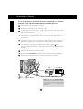
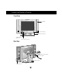
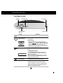
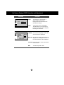
The FLATRON LCD 575MM Flat Panel Monitor has an active matrix TFT
(Thin-Film Transistor) LCD (Liquid Crystal Display).
This monitor is designed for use in small working areas or for those who need
more working space on the desk.
Features
The FLATRON LCD 575MM is a 15-inch (15 inches viewable) intelligent
micropro-cessor based monitor.
Digitally controlled auto-scanning is done with the micro-processor for horizontal
scan frequencies between 31 and 69kHz, and vertical scan frequencies
between 56 - 85Hz.
This monitor provides audio function.Thanks to built in audio function in the
speaker,you can easily separate speakers from the monitor and place them
where you want.
We accomplished to adapt the advanced design and technology to the monitor.
Soft touch buttons on the front panel are simple and allow you to conveniently
adjust a variety of image controls. The absolute flat screen and screen surface
treatment eliminate distracting glares.
It supports resolutions up to 1024x768, and has a wide viewing angle of ±60
degrees horizontal and ±45 degrees vertical.
Plug and play capability if supported by your system.
This monitor has DDC 2B function.*
Compliant with the following regulated specifications :*
- FCC Compliance Statement
- CE Conformity Notice
- EPA ENERGY STAR
- Swedish MPR II
- Swedish TCO’99
*For detailed information, please refer to the Reference Guide provided .
A1
ENGLISH
Introduction
Connecting the Monitor
To set up the monitor, ensure that the power is turned off to the monitor,
computer system, and other attached devices, then follow these steps:
1 Power off both the monitor and computer.
2 Slightly press and pull the latch on Stand cover.
3 Connect one end of the monitor signal cable to the input connector on the
rear panel of the monitor.
4 Connect the other end to the 15-pin connector on the real panel of the
computer and tighter the screws. Be sure the signal cable aligns with the 15pin connector.
4’ Connect the other end of the monitor signal cable to the rear panel of
Macintosh computer through a Macintosh adapter and then tighten screws.
5 Connect the plug from the AC adapter into the base of the monitor 1 .
Connect one end of the AC power cord to the AC adapter 2 and the other
end to a properly grounded AC outlet that is easily accessible and close to the
monitor 3 .
6 Power on the computer, then the monitor.
7 If you see the NO SIGNAL message, check the signal cable and connectors.
8 After using the system, power OFF the monitor, then the computer.
24
V
1
AUDOI
DC OUT
I
DO T
AU OU
DC
MACINTOSH
IBM
Stand cover
D-15P
3
Power
Cord
4
Adapter D-15P
Signal Cable
2 AC adapter
Note : If you see the “OUT OF RANGE”
message, check to make sure your system
is set to one of the factory preset modes
(see page A9), or is set to a resolution and
refresh rate within the specification limits of
this monitor.
A2
4’
Connecting the Monitor
Connection the Audio
1.
2.
Connect the speaker as described in below picture.
3.
Connect the audio cable from the Speaker’s AUDIO IN port 4 to the audio
output port of your computer’s sound card.
Connect the one end of Audio DC power cable,which is attached on the
speaker to AUDIO DC OUT connector 1 and the other end to DC 24V
connector 2 on the back of the speaker.Then connect the audio cable port
which is directly connected to the speaker to AUDIO L-OUT port 3 .
24
2
1
24V
4
V
I
DO
AU OUT
DC
AUDIO
IN
AUDIO
L-OUT
3
PC
4.
After connecting both cables, fix them with cable fixed holder (extra cable
fixed holders are shipped with the speaker).
24
V
I
DO
AU OUT
DC
Cable fixed holder
24V
AUDIO
IN
AUDIO
L-OUT
5.
Turn on the speaker with power button and adjust volume to proper level.
Volume Botton
Used to adjust volume.
Mute Botton
Used to turn ON/OFF mute
function.
Power Botton
Used to turn ON/OFF audio.
A3
Location and Function of Controls
Front View
Speaker
SOUND
SOUND
Power Button
Power Indicator
OSD Button
Buttons
AUTO/SET Button
24
V
Rear View
A
DC UDO
OU I
T
AUDOI
DC OUT
I
DO T
AU C OU
D
Audio DC Power Cable
Audio Cable
Stand cover
Audio Buttons
A4
Control Panel Function
Front Panel Controls
OSD Button
AUTO/SET Button
Power Button
Button
Power Indicator
Control
Function
OSD Button
Button
100
100
AUTO/SET Button
PROCESSING
AUTO CONFIGURATION
Use this button to enter or exit the on screen display.
Use these buttons to choose or adjust items in the on
screen display.
<Shortcut Keys>
• Brightness and Contrast can be adjusted directly
without entering the On Screen Display (OSD) system.
Touch the
buttons to adjust the settings and
then the OSD button to save all changes. The
Brightness and Contrast functions are also available in
the On Screen Display (OSD) menu.
Use this button to enter a selection in the on screen
display.
* AUTO adjustment function
Touch the AUTO/SET button before using OSD menu.
This button is for the automatic adjustment of the screen
position, clock and phase.
Note: Some signal from some graphics boards may not function
properly. If the results are unsatisfactory, adjust your monitor’s
Position, Clock and Phase manually.
Power Button
Use this button to turn the monitor on or off.
Power Indicator
The power indicator light is shown in the power button.
This indicator lights up green when the monitor
operates normally. If the monitor is in DPM (Energy
Saving) mode (stand-by/ suspend/power off), this
indicator color changes to amber.
A5
On Screen Display (OSD) Control Adjustment
Making adjustments to the image size, position and operating parameters of
the monitor are quick and easy with the On Screen Display Control system.
A quick example is given below to familiarize you with the use of the controls.
Following section is an outline of the available adjustments and selections you
can make using the OSD.
NOTE
Allow the monitor to stabilize for at least 30 minutes before making image adjustment.
To make adjustments in the On Screen Display, follow these steps:
1
1
1
2
2
3
3
4
4
4
5
5
5
6
6
6
7
7
7
Press the OSD Button, then the main menu of the OSD appears.
To acces a control, use the
or
Buttons. When the icon you want
becomes highlighted, press the AUTO/SET Button.
Use the
Buttons to adjust the item to the desired level.
Accept the changes by pressing the AUTO/SET Button.
Exit the OSD by Pressing the OSD Button.
A6
On Screen Display(OSD) Selection and Adjustment
You were introduced to the procedure of selection and adjusting an item
using the OSD system.
Listed below are the icons, icon names, and icon descriptions of the items that
are shown on the Menu.
OSD Adjust
Description
Brightness
BRIGHTNESS CONTRAST
Used to adjust the brightness of the
screen.
88
100
Contrast
Adjust the display to the contrast
desired.
COLOR
PRESET
9300K
6500K
RED
GREEN
BLUE
PRESET 9300K/ 6500K
To appear the displays color
temperature.
• 9300K:Slightly bluish white.
• 6500K:Slightly reddish white.
RED
To set your own color levels.
GREEN
To set your own color levels.
BLUE
To set your own color levels.
POSITION
Vertical Position
61
To move image up and down.
39
Horizontal Position
To move picture image left and right.
A7
On Screen Display(OSD) Selection and Adjustment
OSD Adjust
Description
TRACKING
CLOCK
To minimize any vertical bars or
stripes visible on the screen
background.The horizontal screen
size will also change.
PHASE
To adjust the focus of the display.
This item allows you to remove any
horizontal noise and clear or sharpen
the image of characters.
CLOCK
PHASE
SETUP
LANGUAGE
IMAGE SIZE
OSD POSITION
BEEP
ENGLISH
FULL
ON
48.3kHz / 60.0Hz
PRESET MODE
LANGUAGE To choose the language in which the
control names are displayed.
IMAGE SIZE This function displays the image in its
original size or enlarged size so as to
fit in the full screen of the LCD panel.
OSD POSITION To adjust position of the OSD window
on the screen.
To select beep ON or OFF.
BEEP
A8
Video Memory Modes
The monitor has 26 memory locations for display modes, 16 of which are
factory preset to popular video modes.
Display Modes (Resolution)
Display Modes (Resolution)
1
2
3
4
5
6
7
8
9
10
11
12
13
14
15
16
VGA
VGA
VGA
MAC
VESA
VESA
VESA
VESA
MAC
VESA
VESA
MAC
VESA
VESA
VESA
VESA
Horizontal Freq.(kHz)
Vertical Freq.(Hz)
31.47
31.47
31.47
35.00
37.50
43.27
35.16
37.88
48.08
46.88
53.67
49.73
48.36
56.48
60.02
68.67
70
70
60
67
75
85
56
60
72
75
85
75
60
70
75
85
640 x 350
720 x 400
640 x 480
640 x 480
640 x 480
640 x 480
800 x 600
800 x 600
800 x 600
800 x 600
800 x 600
832 x 624
1024 x 768
1024 x 768
1024 x 768
1024 x 768
Note : This LCD monitor has been pre-adjusted to the video mode of
VESA 1024x768 @60Hz.
User Modes
Modes 17-26 are empty and can accept new video data. If the monitor detects
a new video mode that has not been present before or is not one of the preset
modes, it stores the new mode automatically in one of the empty modes
starting with mode 17.
If you use up the 10 blank modes and still have more new video modes, the
monitor replaces the information in the user modes starting with mode 17.
A9
Troubleshooting
Check the following before calling for service.
Display Position is incorrect.
Push the AUTO/SET Button.
If the results are unsatisfactory, adjust the image position using the H position and
V position icon in the on screen display.
On the screen background, vertical bars or stripes are visible.
Push the AUTO/SET Button.
If the results are unsatisfactory, decrease the vertical bars or stripes using the
CLOCK icon in the on screen display.
Any horizontal noise appearing in any image or characters are not clearly
portraid.
Push the AUTO/SET Button.
If the results are unsatisfactory, decrease the horizontal bars using the PHASE icon
in the on screen display.
NO SIGNAL message.
The signal cable is not connected, or is loose. Check and secure the connection.
OUT OF RANGE message appears.
Picture is blank.
The frequency of the signal from the video card is outside the operating range of
the monitor.
Horizontal Frequency: 31kHz-69kHz
Vertical Frequency: 56Hz-85Hz
*Use the graphics board's utility software to change the frequency setting (Refer to the
manual for graphics board).
*You can change the setup to the supported resolution using the Safe Mode (Press the F8
key during booting the system).
The power LED is illuminated amber.
The monitor is in its display power management mode.
There is no active signal coming from the PC.
The signal cable is not fastened securely.
Check the computer power and graphics adapter configuration.
The monitor doesn't enter the power saving off mode (Amber).
Computer video signal is not VESA DPMS standard. Either the PC or the video
controller card is not using the VESA DPMS power management function.
NOTE
If the power indicator(LED) light is blinking amber, may result in abnomal condition of
the monitor.
Then press a power ON/OFF button on the front panel control and call your service
technician for more information.
A10
Specifications
Display
Sync Input
Video Input
Audio
Power
Consumption
Dimensions
Power Input
AC Adapter
Weight
Tilt Range
Environment
Conditions
Type
15 inch (38.1cm) Flat Panel Active matrix-TFT LCD
Anti-Glare coating
Viewable Size
15 inch (38.1cm)
Pixel pitch
0.297 x 0.297mm
True color
262,144 color
Horizontal Freq.
31kHz - 69kHz (Automatic)
Vertical Freq.
56Hz - 85Hz (Automatic)
Input form
Separate, TTL, Positive/Negative
Signal input
15 pin D-Sub connector
Display Area
304.1 x 228.1mm / 11.97 x 8.98 inch
Separate, RGB Analog, 0.714Vp-p/75ohm,
Input Form
Positive
Resolution (max.)
VESA 1024 x 768 @ 85Hz
RMS Audio Output 2W(R+L)
Input Sensitivity
0.7Vrms
Speaker Impedance 8Ω
Normal(Max.)
Stand-by/Suspend
Power Off
Width
Height
Depth
DC 24V 1.5A
Input
Output
Net
Down
Up
Operating condition
Temperature
Humidity
Storage condition
Temperature
Humidity
≤ 36W
≤ 3W
≤ 3W
39.4 cm / 15.5 inches (without speaker)
52.2 cm / 20.6 inches
37.87 cm / 14.9 inches
16.18 cm / 6.37 inches
AC 100-240V, 50 - 60Hz, 1.2A - 0.6A
+
DC 24V
1.5A 5.1 kg / 11.24 lbs (without speaker)
6.1 kg / 13.4 lbs
5˚
30˚
10˚C to 35˚C
10% to 80% non-condensing
-20˚C to 60˚C
5% to 95% non-condensing
NOTE
Information in this document is subject to change without notice and does not
represent a commitment on the part of LG Electronics Inc.
A11