1
http://www.omega.com
e-mail: info@omega.com
CL526
Multifunction Indicator-Simulator
OMEGAnetSM On-Line Service
Internet e-mail
http://www.omega.com
info@omega.com
Servicing North America:
USA:
ISO 9001 Certified
Canada:
One Omega Drive, Box 4047
Stamford, CT 06907-0047
Tel: (203) 359-1660
e-mail: info@omega.com
FAX: (203) 359-7700
976 Bergar
Laval (Quebec) H7L 5A1
Tel: (514) 856-6928
e-mail: info@omega.ca
FAX: (514) 856-6886
For immediate technical or application assistance:
Usa and Canada:
Sales Service: 1-800-826-6342 / 1-800-TC-OMEGASM
Customer Service: 1-800-622-2378 / 1-800-622-BESTSM
Engineering Service: 1-800-872-9436 / 1-800-USA-WHENSM
TELEX: 996404 EASYLINK: 62968934 CABLE: OMEGA
Mexico and
Latin America:
Tel: (95) 800-826-6342
En Español: (95) 203-359-7803
e-mail: espanol@omega.com
FAX: (95) 203-359-7807
Servicing Europe:
Benelux:
Czech Republic:
France:
Germany/Austria:
United Kingdom:
ISO 9002 Certified
Postbus 8034, 1180 LA Amstelveen, The Netherlands
Tel: (31) 20 6418405
Toll Free in Benelux: 0800 0993344
e-mail: nl@omega.com
ul. Rude armady 1868, 733 01 Karvina-Hranice, Czech Republic
Tel: 420 (69) 6311899
Toll free: 0800-1-66342
e-mail: czech@omega.com
9, rue Denis Papin, 78190 Trappes
Tel: (33) 130-621-400
Toll Free in France: 0800-4-06342
e-mail: france@omega.com
Daimlerstrasse 26, D-75392 Deckenpfronn, Germany
Tel: 49 (07056) 3017
Toll Free in Germany: 0130 11 21 66
e-mail: info@omega.de
One Omega Drive , River Bend Technology Centre
Northbank, Irlam, Manchester
M44 5EX, England
Tel: 44 (161) 777-6611
Toll Free in United Kingdom: 0800-488-488
e-mail: info@omega.co.uk
FAX: (31) 20 6434643
FAX: 420 (69) 6311114
FAX: (33) 130-699-120
FAX: 49 (07056) 8540
FAX: 44 (161) 777-6622
It is the policy of OMEGA to comply with all worldwide safety and EMC/EMI regulations that apply. OMEGA is constantly
pursuing certification of its products to the European New Approach Directives. OMEGA will add the CE mark to every
appropriate device upon certification.
The information contained in this document is believed to be corrected but OMEGA Engineering Inc. accepts no liability for any errors it
contains, and reserves the right to alter specifications without notice.
WARNING: These products are not designed for use in, and should not be used for, patient connected applications.
2
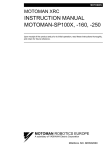
INTRODUCTORY NOTE
ATTENTION: THIS MANUAL MUST BE REFERRED TO INSTRUMENTS WITH SERIAL NUMBER 005980 ONWARDS.
This publication contains operating instructions, as well as a description of the principles of operation, of
CL526 multifunction portable calibrator.
This information covers all models of the instrument, including the basic equipment and its options and
accessories.
This manual is a complete “USER GUIDE”, providing step-by-step instructions to operate the instrument in
each of its designed functions.
OMEGA has used the best care and efforts in preparing this book and believes the information in this
publication are accurate. The OMEGA products are subjected to continuous improvement, in order to pursue
the technological leadership; these improvements could require changes to the information of this book.
OMEGA reserves the right to change such information without notice.
No part of this document may be stored in a retrieval system, or transmitted in any form, electronic or
mechanical, without prior written permission of OMEGA Engeneering.
CL526 multifunction portable calibrator uses sophisticated analogic and digital technologies. Any
maintenance operation must be carried out by qualified personnel ONLY. We recommend to contact our
technicians for any support requirements.
The instrument is supplied by a Ni-MH rechargeable battery pack or by 100, 115, 230V ±10% 50/60Hz line
supply using the special power supply module provided with the CL526 when the rechargeable battery is
ordered.
CL526 is fully tested in conformity with the directive n°89/336/CEE Electromagnetic Compatibility. OMEGA
shall not be liable in any event, technical and publishing error or omissions, for any incidental and
consequential damages, in connection with, or arising out of the use of this book.
3
TABLE OF CONTENTS
1
GENERAL PERFORMANCE ............................................................................................................... 6
1.1
1.2.1
2
Specifications ...................................................................................................................................................7
Table of ranges and accuracy.....................................................................................................................9
GENERAL FEATURES ...................................................................................................................... 10
2.1
2.2
2.3
2.4
2.5
2.6
2.7
2.8
2.9
2.10
3
Input and output flexibility ...............................................................................................................................10
Self calibration ................................................................................................................................................10
Keyboard ........................................................................................................................................................10
Display............................................................................................................................................................10
Digital interface...............................................................................................................................................10
Scale factor function .......................................................................................................................................10
Square root function .......................................................................................................................................10
Average measurements .................................................................................................................................10
Simulation programs.......................................................................................................................................10
Case ..........................................................................................................................................................11
PHYSICAL DESCRIPTION ................................................................................................................ 12
4
FUNCTIONAL DESCRIPTION ........................................................................................................... 13
4.1
4.2
4.3
4.4
4.5
4.6
4.7
4.8
4.9
4.10
4.11
4.12
Power supply ..................................................................................................................................................13
Keyboard ........................................................................................................................................................13
Input circuit .....................................................................................................................................................14
Microprocessor ...............................................................................................................................................15
Firmware ........................................................................................................................................................15
Digital display .................................................................................................................................................15
Digital to analog converter..............................................................................................................................15
Battery charger. Operation from line source...................................................................................................16
Digital interface...............................................................................................................................................16
Resistance and Rtd measurements...........................................................................................................16
Resistance and Rtd simulation ..................................................................................................................17
Thermocouples input-output circuit............................................................................................................17
5
UNPACKING ...................................................................................................................................... 18
6
PRE-OPERATIONAL CHECK ........................................................................................................... 19
7
ELECTRICAL CONNECTIONS.......................................................................................................... 20
7.1
7.2
8
POWER SUPPLY ............................................................................................................................... 23
8.1
8.2
8.3
9
Wiring practice...............................................................................................................................................20
Thermocouple wires .......................................................................................................................................21
Rechargeable batteries ..................................................................................................................................23
Battery Charger ..............................................................................................................................................23
How to maximize the battery life.....................................................................................................................23
OPERATION & APPLICATIONS ....................................................................................................... 24
9.1
Power ON .......................................................................................................................................................24
9.2
Battery voltage indication ...............................................................................................................................24
9.3
Operating mode set up ...................................................................................................................................24
9.3.1
IN - OUT mode selection ...........................................................................................................................25
9.3.2
Parameter or sensor selection ...................................................................................................................25
9.3.3
Tecnical unit...............................................................................................................................................26
9.3.4
Decimal point position................................................................................................................................26
9.3.5
International Temperature Scale................................................................................................................26
9.3.6
Rj mode .....................................................................................................................................................26
9.3.7
Convert function.........................................................................................................................................26
9.3.8
Average readings.......................................................................................................................................27
9.3.9
IN-OUT data memories..............................................................................................................................27
9.3.9.1
Data memory configuration........................................................................................................................27
9.3.9.2
Data memory manual recall ..................................................................................................................28
9.3.9.3
Data memory automatic scanning.........................................................................................................28
9.3.9.4
Manual step advance.................................................................................................................................29
9.3.10
Automatic simulation cycle ........................................................................................................................29
9.3.10.1
Simulation cycle selection .....................................................................................................................29
9.3.10.2
Simulation cycle ....................................................................................................................................31
9.3.11
Rj compensation mode check....................................................................................................................31
9.3.12
Scale factor program .................................................................................................................................32
9.3.13
Installation parameter procedure ...............................................................................................................34
9.3.13.1
Firmware version code - Serial number ................................................................................................34
4
9.3.13.2
10
10.1
10.2
10.3
10.4
10.5
10.6
11
11.1
11.2
11.3
11.4
External Rj compensation .....................................................................................................................34
DIGITAL INTERFACE ........................................................................................................................ 35
Digital interface data program mode...............................................................................................................35
Digital output wiring practice...........................................................................................................................35
TTL to RS 232 adapter ...................................................................................................................................36
Communication protocol from CL526 to a PC ................................................................................................36
Computer request for CL526 settings.............................................................................................................40
Communication programs ..............................................................................................................................44
MAINTENANCE.................................................................................................................................. 46
Safety recommendations................................................................................................................................46
Faulty operating conditions.............................................................................................................................46
Protection fuses..............................................................................................................................................47
Storage...........................................................................................................................................................47
5
1
GENERAL PERFORMANCE
A complete system for testing, measuring and calibrating built in a single, compact portable instrument. The portable
calibrator CL526 is a multifunction instrument designed to meet, in a modern and practical way, the needs of
instrumentation engineers, both in laboratory and field work.
Accurate, compact, rugged, easy to use; the ideal solution for measuring and simulating:
millivolts
•
volts
•
milliamperes (active and passive loop)
•
ohms
•
thermocouples
•
resistance thermometers
•
The CL526 has been developed using the most advanced microprocessor technology to provide high accuracy on
extended ranges and a powerful operating flexibility.
The modular firmware includes the algorithms of thermocouples and resistance thermometers in accordance with IEC,
DIN standards. IPTS68 and ITS90 linearization are memory stored and can be selected through the keyboard.
The simulation-measurement of resistance and temperature with resistance thermometer uses a special proprietary
active circuit.
An unique internal automatic Rj compensation system allows the CL526 to provide accurate input and output readings
over wide operating conditions, with a temperature range from -5°C to +50°C. Further, external compensation is
available with temperature adjustable from -50°C to +100°C.
The selection of operating functions is made on a polycarbonate thermoformed membrane keyboard which assures up to
one million operations per key.
Two thick film membrane “slidewires” are used to set the simulated signal value.
Measured and simulated values are indicated on a high quality LCD dot matrix display which provides good contrast
even in poor light conditions.
A menu-driven procedure allows for the generation of up to 60 memory stored values, or, for continuous or step ramp
values.
The instrument carries out mathematical functions for averaging unstable input signals and, in combination with scale
factor, square root calculation.
The case, made in shock-resistant ABS, is ergonomically designed for easy practical use.
The instrument is powered by four Ni-MH rechargeable batteries; an external battery charger is supplied as a standard
accessory.
6
1.1
Specifications
•
IN/OUT parameters:
- mV, V, mA, Ω
- Tc type J, K, T, R, S, B, N, C, E, F, U, L, G, D
- Rtd type Pt100, Ni100 and Ni120
•
Reference junction compensation:
- automatic internal with Pt100 sensor from -5°C to +50°C;
- external with manual setting from -50°C to +100°C
•
Rj compensation drift:
± 0.015°C/°C
•
Rj compensation error:
±0.15°C
•
In/Out ranges:
see following tables
•
Resolution:
see following tables
•
Limits of error:
see following tables
•
Common mode rejection:
> 130 dB at 50/60 Hz
•
Normal mode rejection:
> 60 dB at 50/60 Hz
•
Temperature stability:
span
± 0.005% of the reading/°C
zero
± 0.2 µV /°C
•
Output impedance (emf output and Tc):
< 0.5 Ω with maximum current of 0.5 mA
•
Input impedance:
> 10 MΩ (> 1MΩ on 10 V range)
•
Source resistance effect:
1 µV error for 1000 Ω source resistance
•
Rtd and Ω simulation excitation current:
from 0.2 to 5 mA
•
Rtd and Ω measurement excitation current:
0.25 mA
•
Rtd cable compensation:
up to 100 Ω (each wire)
•
Shunt resistance (mA ranges):
38 Ω
•
Maximum resistance load:
1000 Ω ( 20mA )
•
Maximum input over voltage dc:
50 V (mV, V, Tc)
5 V (Rtd)
•
Display:
high contrast dot matrix LCD (7x5 dots per character -16 characters)
•
Engineering unit indications:
up to 4 characters shown directly on the display
•
Scale factor:
zero and span programmable within -10000 and +10000
•
Square root:
in combination with scale factor (display limits 0 and +2500)
7
•
Calibration:
semi-automatic procedure
•
Power supply:
n. 4 Ni-MH batteries 1.25 V 1.2 A/h
•
Battery life:
4 hours with 20 mA simulation mode
12 hours on measuring mode
•
Recharge time:
10 hours with instrument switched -Off- (at 90%)
•
Battery voltage:
value indicated on the display
•
Program release identification:
release code on the display
•
Operating environment temperature range:
from -5°C to +50°C
•
Storage temperature range:
from -30°C to +60°C
•
Case:
ABS with internal metal coating
•
Dimensions:
120x60x230 mm
•
Weights:
net 1 Kg
gross with packing 2.5 Kg
8
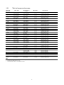
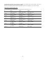
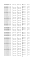
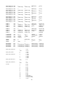
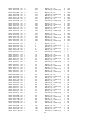
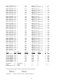
1.2.1
Sensor or
parameter
Tc type J
Table of ranges and accuracy
Total range
High accuracy
range
Resolution
Limit of error
-210 to +1200°C
-346 to +2192°F
-270 to +1370°C
-454 to +2498°F
-270 to +400°C
-454 to +752°F
0 to +1760°C
32 to +3200°F
0 to +1760°C
32 to +3200°F
200 to +1820°C
392 to +3308°F
0 to +2300°C
32 to +4172°F
0 to +2300°C
32 to +4172°F
0 to +2300°C
32 to +4172°F
-200 to +400°C
-328 to +752°F
-200 to +760°C
-328 to +1400°F
0 to 1300°C
+32 to 2372°C
-270 to +1000°C
-454 to +1832°F
0 to 1400°C
32 to 2552°F
-190 to +1200°C
-310 to +2192°F
-150 to 1300°C
-220 to 2372°F
-150 to 400°C
-202 to 752°F
500 to 1700°C
932 to 3092°F
600 to 1760°C
1112 to 3200°F
1000 to 1820°C
1832 to 3308°F
1150 to 2300°C
2102 to 4172°F
300 to 2000°C
572 to 3632°F
300 to 2000°C
572 to 3632°F
-150 to +400°C
-238 to +752°F
-200 to 760°C
-328 to 1400°F
0 to 1300°C
32 to 2372
-200 to +1000°C
-328 to +1832°F
0 to 1400°C
32 to 2552°F
0.1°C
0.1°F
0.1°C
0.1°F
0.1°C
0.1°F
0.1°C
0.1°F
0.1°C
0.1°F
0.1°C
0.1°F
0.1°C
0.1°F
0.1°C
1°F
0.1°C
0.1°F
0.1°C
0.1°F
0.1°C
0.1°F
0.1°C
0.1°F
0.1°C
0.1°F
0.1°C
0.1°F
± (0.02% of rdg +0.1°C)
± (0.02% of rdg +0.18°F)
± (0.02% of rdg +0.1°C)
±(0.02% of rdg +0.18°F)
± (0.02% of rdg +0.1°C)
±0.02% of rdg +0.18°F)
± (0.02% of rdg +0.3°C)
± (0.02% of rdg +0.154°F)
± (0.02% of rdg +0.3°C)
± (0.02% of rdg +0.154°F)
±(0.02% of rdg +0.4°C)
± (0.02% of rdg +0.172°F)
± (0.02% of rdg +0.4°C)
± (0.02% of rdg +0.172°F)
± (0.02% of rdg +0.4°C)
± (0.02% of rdg +0.172°F)
± (0.02% of rdg +0.4°C)
± (0.02% of rdg +0..72°F)
±(0.02% of rdg +0.1°C)
± (0.02% of rdg +0.18°F)
± (0.02% of rdg +0.1°C)
± (0.02% of rdg +0.18°F)
±(0.02% of rdg +0.1°C)
± (0.02% of rdg +0.18°F)
±(0.02% of rdg +0.1°C)
± (0.02% of rdg +0.18°F)
±(0.02% of rdg +0.1°C)
± (0.02% of rdg +0.18°F)
-200 to +850°C
-328 to +1562°F
-200 to +600°C
-328 to +1562°F
-200 to +850°C
-328 to +1562°F
-200 to +850°C
-328 to +1562°F
-200 to +600°C
-328 to +1562°F
-200 to +850°C
-328 to +1562°F
0.1°C
0.1°F
0.1°C
0.1°F
0.1°C
0.1°F
±(0.02% of rdg +0.1°C)
± (0.02% of rdg +0.18°F)
±(0.02% of rdg +0.1°C)
± (0.02% of rdg +0.18°F)
±(0.02% of rdg +0.1°C)
± (0.02% of rdg +0.18°F)
Ni100
-60 to +180°C
Ni120
0 to +150°C
32 to +302°F
-60 to +180°C
-76 to +356°F
0 to +150°C
32 to +302°F
0.1°C
0.1°F
0.1°C
0.1°F
±(0.02% of rdg +0.1°C)
± (0.02% of rdg +0.18°F)
±(0.02% of rdg +0.1°C)
± (0.02% of rdg +0.18°F)
mV
mV
-18.000 to +22.000
-10.00 to +100.00
mV
V
0.0 to +1000.0
0.000 to +10.000
-10.000 to +22.000
-10.000 to +21.000
+21.00 to +53.00
+53.00 to +100.00
0.0 to +1000.0
0.000 to +10.000
1 µV
10 µV
10 µV
10 µV
100 µV
1 mV
± (0.01% of rdg +3µV)
± (0.01% of rdg +3µV)
± (0.01% of rdg +3µV)
± (0.01% of rdg +6µV)
± (0.01% of rdg +40µV)
± (0.02% of rdg +0.4mV)
mA
Ω (IN)
Ω (OUT)
0.000 to +21.000
0.0 to 400.0 Ω
0.0 to 400.0 Ω
0.000 to +21.000
0.0 to 400.0 Ω
0.0 to 400.0 Ω
1 µA
10 mΩ
10 mΩ
± (0.02% of rdg +0.5 µA)
± (0.02% of rdg +38mΩ)
± (0.03% of rdg +78mΩ)
Tc type K
Tc type T
Tc type R
Tc type S
Tc type B
Tc type C
Tc type G
Tc type D
Tc type U
Tc type L
Tc type N
Tc type E
Tc type F
Pt 100 (IEC)
Pt100 (JIS)
Pt100 (US)
Note:
•
•
•
Accuracy shown are based on tests at 23°C ±5°C for 360 days
All Input ranges: additional error ± 1 digit
Traceability chart to WECC or SIT available on request
9
2
2.1
GENERAL FEATURES
Input and output flexibility
Advanced flexibility of performance has been achieved using microprocessor technology. Each instrument, through a
menu-driven procedure, allows measurement or simulation of mV, V, mA, Ω, or any normalized IEC, DIN and JIS
thermoelectric sensor J, K, T, R, S, B, C, U, L, N, E, F, G, D, Pt100, Ni100 and Ni120.
The microprocessor performs automatic polynomial linearization and cold junction compensation to assure high
accuracy. °C or °F selection can be made through a reconfiguration set-up.
2.2
Self calibration
The hardware-firmware design allows an automatic calibration of the instrument. A precision source (from 0 to 10V), a
0°C reference system, a standard resistor of 400Ω (±0.02% accuracy) and an ohmmeter are necessary. The calibration
procedure is protected by a security code.
2.3
Keyboard
A thermoformed metal-click tactile polycarbonate membrane keyboard, with a working life of one million operations per
key, seals the internal electronics from the surrounding environment.
Contact closure of membrane keys is acknowledged, as a coded signal, directly by the microprocessor. Two membrane
slidewires (patent pending) allow operator setting of the simulation value.
2.4
Display
The high contrast alphanumeric LCD display with dot matrix (7x5 dots per character-16 characters) allows easy readings,
even in poor light conditions, and simultaneously indicates the active function (measured or simulated), engineering unit
and type of sensor or signal.
2.5
Digital interface
A digital interface with TTL logic levels is available as standard for communication with external units.
A serial data port provides communication capability at a logic level of 0-5V (four wires: Tx, Rx, GND, Vcc).
A seven-pole cable, with mini DIN connector is supplied as a standard accessory, and a TTL to RS 232 adaptor is
available as an option.
2.6
Scale factor function
Easy menu-driven set-up to read or simulate electrical signal value in terms of engineering units. Four programmable
alphanumeric characters are available on the display to show the symbol of the parameter (i.e. mbar, %RH, %CO, etc.).
The display will indicate the scaled input/output value.
2.7
Square root function
Can be programmed during the set-up procedure (e.g. linear ranges only) to obtain direct readings of flow from a dP
transmitter signal. The display limits are 0 and +2500.
2.8
Average measurements
For the measurement of unstable input signals by a progressive averaging of a programmable number of conversions.
2.9
Simulation programs
Menu-driven set-up to generate:
10
•
•
•
2.10
a continuous or step ramp output where the total time, the start point, the end point and the size of the step are
requested by the set-up procedure to run the program;
a manual repeat increment through keyboard;
an automatic sequence of up to 60 stored values (20 groups of 3 memories).
Case
The case is designed for easy hand held operation and transportation.
The body is injection moulded, shock-resistant ABS with internal metal coating .
A leather carrying case with shoulder strap is supplied with the instrument as a standard accessory.
11
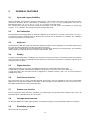
3
PHYSICAL DESCRIPTION
The CL526 portable calibrator consists of a rugged and compact case, a mother board with all base functions, a
daughter board for the auxiliary functions, a tactile membrane keyboard, an LCD display and a group of four nickelcadmium rechargeable batteries.
The internal surface of the case is metal coated to improve the characteristics of electrical noise shielding and thermal
equalization of all internal circuits.
The battery container is located on the lower part of the case, and is accessible through a cover fastened by a metal
screw.
The two halves of the case are joined together by four metal screws located on the back side.
The leather case, with shoulder strap, assures better protection of the instrument against mechanical knocks or
scratches.
12
4
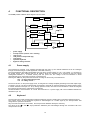
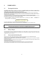
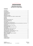
FUNCTIONAL DESCRIPTION
The CL526 portable calibrator block diagram is shown below.
External battery
charger
A
Ni-MH
Batteries
Converters for
backligh
Reference
junction
Power supply
Rj signals
Digital
interface
Display
A
D/A
(converter)
Microprocessor
Keyboard
Signal OUT
output signal
Gain Control
Comparator
and buffer
output signal
IN/OUT
Switch
IN/OUT terminals
•
•
•
•
•
•
•
4.1
power supply
microprocessor (central unit + memory)
input circuit
cold junction compensator (Rj)
LCD display
operative keyboard
digital to analog converter
Power supply
The instrument is powered, if not otherwise specified with the order, by four internal batteries that can be recharged
through an external charger module supplied as a standard accessory.
The internal batteries are Ni-MH rechargeable AA type with a nominal voltage of 1.25 V. The jumper “J1” (mounted on
the mother board), when soldered into the “B” position, allows the instrument to be powered by the four internal
rechargeable batteries or, if needed, directly from the power line. The voltage of the four batteries in series
(approximately 5V) is connected to the input of a hybrid circuit.
Pressing the <ON> key will provide the two levels of voltage for the circuitry of the instrument:
+ 5 V for logic and analog circuits
- 5 V for analog circuits
The second section, on the power supply circuit, is configured as a voltage multiplier generating for the final output stage,
a voltage of 24V dc. The above voltage levels are required to work with an external resistance of 1000Ω maximum when
in current simulation mode (20 mA - 20 V). During operative modes, other than current simulation a diode de-energizes
the hybrid circuit reducing the overall power consumption.
Recommendations and instructions to convert the instrument for a power supply with normal alkaline batteries are
described in par. 8.3.
4.2
Keyboard
The front panel is a tactile polycarbonate membrane keyboard, and has a working life of one million operations per key.
The contact closure of the membrane keyboard is acknowledged as a coded signal by the microprocessor that
recognizes the operators instructions.
Keys are interconnected on a 4x3 matrix; the microprocessor identifies directly the active key.
The values of the <▲
▲> and <▼
▼> keys (membrane slidewires) are acknowledged through the converters built in the
microprocessor chip.
13
ON
OFF
IPTS68-ITS90
Rj
<▲
▲> <▼
▼>
STORE
<←
←> <→
→>
START
END
STEP
MODE
SOAK
TIME
0, 1, 2
°C/°F
SELECT
AVERAGE
IN/OUT
CONVERT
AUTORAMP
PROGRAM X
BATTERY
ENTER
SHIFT
LAMP
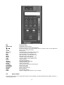
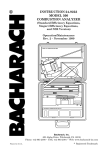
4.3
Power ON switch
Power OFF switch
Temperature Scale selection
Reference junction internal-external selection
Membrane slidewires to set the simulation value (to scroll the menu of input tables and
library of engineering characters).
Memory load
Parameter selection or decimal point position
Low limit setting of the simulation cycle
High limit setting of the simulation cycle
Step value setting of the simulation cycle
Simulation cycle mode selection
Soak time setting of the simulation cycle
Total time setting of the simulation cycle
In/Out memories
Technical unit selection
Parameter selection procedure
Average measurements
In/Out mode selection
Technical unit to equivalent electrical signal
Ramp program start
Scale factor program
Battery voltage indication
Memory load key
Key secondary function
Display backlight switch (special - only on request)
Input circuit
The input circuit is based on an output buffer wired as an error amplifier. The input signal drives the negative channel ( - )
of the integrated circuit.
14
The microprocessor recognizes if the D/A converter is generating a voltage signal higher or lower than the input signal
and gives correcting instructions to keep the input amplifier output on the nearest value to zero. In the above conditions
the microprocessor acknowledges the value of the input signal as equivalent to the setting of the digital to analog
converter.
µP
D/A
IN
4.4
+
-
Display
Ouput buffer / input amplifier
Microprocessor
The microprocessor handles all the logic functions of the instrument, performs the linearization for non linear
transducers, compensates for the reference junction temperature, drives the digital display and acknowledges all
operator instructions.
The heart of the circuit is a single-chip microcomputer that utilizes HCMOS technology to provide the low power
characteristics and high noise immunity of CMOS plus the high speed operation of HMOS.
The microcomputer provides highly sophisticated, on- chip peripheral functions including: 256 bytes of static RAM, an 8
channel analog to digital (A/D) converter (used to read the Rj value, the setting of the input comparator, the battery
package voltage and the value of the two membrane slidewires), a serial communication interface (SCI) subsystem, and
a serial peripheral interface (SPI) subsystem.
The microprocessor works with an 8-bit communication bus to the EPROM and EEPROM memories and is interfaced
with a decoder, a latch of address and an inverter-driver.
4.5
Firmware
The operating system firmware handles all logic instructions to the internal peripheral circuits and performs the
computation of the linearization equations.
The application system firmware is resident on the non-volatile memory (EEPROM) of the microprocessor chip. It is used
to store the installation parameters (autocalibration data, programs data, etc.)
4.6
Digital display
The digital display, mounted on an auxiliary board, uses high contrast LCD technology (STN liquid). Character
generation is made by a secondary dedicated microprocessor driven by two integrated circuits with signal input from the
bus of the main microprocessor.
The 16 characters are displayed with a 7x5 dot matrix. On request, CL526 can be equipped with a backlight device for
easy readings in poor light conditions.
4.7
Digital to analog converter
A 14-bit digital to analog device, driven directly by the microprocessor converts the digital value of the selected
parameter into an analog current output.
The current signal is converted into a voltage signal across a resistance strip network.
Two low thermal emf relays select one of the four available output points as a function of the selected range. The ranges
are:
-18
to
+22 mV
Tc type R, S, B, T and the negative portion of all Tc’s
-0.2 to
+54 mV
all other thermocouples
-0.2 to
+100,1 mV
100 mV range and Rtd
-2
to
+1001 mV
1000 mV range and 0-20 mA range
-0.02 to
+10.010 V
10 V range
The above signal, through an output buffer, is sent to an integrated circuit that will generate the voltage or current
requested by the operator keyboard settings.
15
µP
D/A
1000 mV
x 1000 multipl.
100 mV
Keyboard
Out
54 mV
22 mV
4.8
Battery charger. Operation from line source
ATTENTION: ONLY FOR USE WITH NI-MH BATTERIES.
The auxiliary module, supplied as a standard accessory, allows operation from 110-120 Vac or 220-240 Vac 50/60 Hz.
The calibrator, if needed, can be operated directly from a line source through the charger. The plastic case of the battery
charger incorporates the line voltage plug and a cable with connector for interconnection to the instrument. The charger
circuit is designed with an insulating transformer and a voltage stabilizer circuit.
The step-down transformer reduces the power line (110-120 Vac or 220-240 Vac nominal) to a value of 10 Vac. The
above voltage is full wave rectified, filtered and stabilized. The output voltage of 6,6 V is the ideal value to recharge the
internal Ni-MH batteries.
4.9
Digital interface
The digital interface circuit is essentially based on the serial communication interface subsystem (SCI) on the chip of the
microprocessor at 0 to +5V level.
An adaptor to convert TTL to RS 232 voltage levels can be obtained on request.
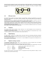
4.10
Resistance and Rtd measurements
The resistance thermometer (Rtd) is connected to terminals A-B-C in a 3-wire configuration (see figure on the next
page).
Two constant current generators are provided by the auxiliary module for supplying the Rtd.
The first half of “IC1” generates the negative current IA= - 0.25 mA that flows from terminal B to terminal A through the
Rtd and line resistances RLA and RLB. IA is kept constant by the microprocessor that controls the zero voltage level.
The second half of “IC 1”, with the associated resistors, generates the positive current IC that flows from terminal C to
terminal B through line resistances RLC and RLB. Current IC is kept exactly = 2 x IA, so the resultant current IB = IC - IA
flows through RLB. The input measured signal across terminals A and B is the algebraic sum of drop voltages across
Rtd and line resistances RLA and RLB. As drop voltages across RLA and RLB are exactly the same (providing that line
resistances RLA and RLB are equals), but with opposite poles, the resultant voltage across terminals A and B is
proportional to Rtd resistance variation, with no influence of line resistance.
The measured signal is then handled by the microprocessor that linearizes it and displays the corresponding value in
engineering units.
IA = - 0.25 mA
IC1/1
A
RLA
Rtd
IB = IC - IA = + 0.25 mA
RLB
B
IC = + 0.5 mA
IC1/2
C
RLC
16
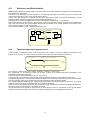
4.11
Resistance and Rtd simulation
CL526 portable calibrator is equipped with an electronic circuit for the active simulation of platinum and nickel resistance
thermometers and resistances.
It is based on the assumption that the instrument to be calibrated will supply the excitation current to the sensor; this
current must be between 0.2 and 5 mA ( typical working values ).
A lower value will generate an insufficient precision level and a higher current won’t permit the simulation of high
resistance values ( maximum voltage drop on the simulated resistance is 2 V ).
The excitation current must be applied to the pertinent terminals as indicated in par. 7.1 (simulation).
That current, flowing through resistance “ Ra“ (precision ± 0.01%) will generate a voltage drop that will be amplified and
sent to the D/A converter. The output amplifier will simulate the variation of the output resistance as a function of the
value set by the operator through the keyboard.
The connection between “+” and “-” terminals must be left open.
µP
Set
D/A
Out
Ouput amplifier
Instrument
to be
calibrated
Ref
Keyboard
Input amplifier
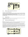
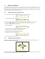
4.12
Ra
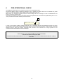
Thermocouples input-output circuit
A thermocouple, a temperature sensor, in its most common form consists of two wires of different composition, joined
together at one end. The two wires are joined together at two points which have different temperatures.
Tc wires
Reference Junction
emf
output
Copper wires
Measuring junction
The reference junction is also often, but less preferably, called the “cold” junction.
The temperature of the reference junction can be held constant or its variation electrically compensated in the
associated measuring instrumentation.
The second junction is the measuring junction (or “hot” junction).
A thermocouple is a practical tool for temperature sensing because it generates a measurable electrical signal.
The signal is proportional to the temperature difference between the measuring and reference junctions and is defined,
by means of tables, based on the International Practical Temperature Scales (IPTS68 or ITS90).
The portable calibrator CL526 has the reference junction located in the negative (black) terminal post. To improve
overall accuracy the terminals are designed with a very low thermal capacity.
Inside the body of the negative terminal is placed a thin film Pt100 resistance thermometer that dynamically measures,
with high accuracy, the temperature of the reference junction.
The microprocessor uses the above signal (Pt100) to adjust the input signal to compensate for the Rj temperature.
Reference junction compensation can be internal or external, depending upon the application requirements.
17
5
UNPACKING
Remove the instrument from its packing case and remove any shipping ties, clamps, or packing materials.
Carefully follow any instructions given on any attached tags.
Inspect the instrument for scratches, dents, damage to case corner etc. which may have occurred during shipment.
If any mechanical damage is noted, report the damage to the shipping carrier and then notify OMEGA directly or its
nearest agent, and retain the damaged packaging for inspection.
A label, inside the battery container, indicates the serial number of the instrument.
Refer to this number for any inquiry for service, spare parts supply or application and technical support requirements.
OMEGA will keep a data base with all information regarding your instrument.
18
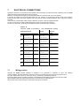
6
PRE-OPERATIONAL CHECK
The CL526 portable calibrator is powered by four Ni-MH rechargeable batteries.
The external battery charger, supplied as standard, may be ordered for either 110/120 Vac or 220/240 Vac power
source. To modify the charger’s power voltage follow the instructions in par. 8.2.
Before using the instrument carefully verify the nominal voltage value of the charger; in case of modification do not
forget to correct the pertinent label.
The instrument should be used in environments where the temperature does not exceed the specified limits (from -5°C to
+50°C) and where the relative humidity is lower than 95%.
Out 1248.3°C
Tc
In case of “low” battery condition (voltage lower than 4.6 V) the display will show the appropriate symbol. An empty
symbol means that the battery package has enough energy for about 30 minutes operation. A black symbol means that
batteries charge is below the minimum acceptable level: operation of the instrument is no longer possible. In this
condition the instrument batteries must be recharged.
WARNING
THE INSTRUMENT IS SUPPLIED WITH NI-MH RECHARGEABLE BATTERIES.
DO NOT USE NORMAL ALKALINE BATTERIES.
ALKALINE BATTERIES, WHEN CONNECTED TO A DC VOLTAGE SUPPLY UNDERTAKE AN OVERHEATING PROCESS WITH
EXPLOSION.
19
A RISK OF
7
ELECTRICAL CONNECTIONS
Appropriate extension wires should be used between the thermocouple (or instrument under calibration) and the CL526
unless the thermocouple leads permit direct connection.
Make sure that both thermocouple and compensating cable are connected with the correct polarity.
If in doubt, the polarity of the compensating leads can be checked by connecting a length of lead to the indicator,
shorting the free ends of the wires together and noting that the indicator reading increases when the wires connection
is heated.
Color codes of compensating cables change in different countries. Check the appropriate table.
For Rtd connection use a cable of adequate gauge to lower the overall input resistance.
The use of a cable with a good resistance balance between conductors is also necessary.
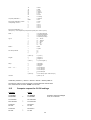
Table A
Colour code & polarity
Thermocouple
E
J
K
S
T
B
N
7.1
Wires
Colour
code
Chromel
Purple
Chromel
( + )
Constantan
Iron
( - ) Constantan
( + ) Iron
Constantan
(
Chromel
( + )
Alumel
R
for extension wires
(
-
) Constantan
Chromel
-
) Alumel
Red
White
Red
Yellow
Red
Pt 13% Rh
Platinum
( + ) Copper
( - ) Alloy 11
Black
Red
Pt 10% Rh
( + )
Black
Platinum
( -
Copper
( + )
Constantan
Pt 6% Rh
( - ) Constantan
( + ) Copper
Pt 30% Rh
( -
Nicrosil
( + )
Nisil
( -
Copper
) Alloy 11
Copper
Red
Blue
Red
) Copper
Nicrosil
) Nisil
Orange
Red
Wiring practice
Although the CL526 portable calibrator is designed to be insensitive to transients or noise, the following
recommendations should be followed to reduce ac pick up in the signal leads and to ensure good performance.
The input leads should not be run near ac line wiring, transformers and heating elements.
Input/output leads should, if possible, be twisted and shielded with the shield grounded at the end of the cable.
When shielded cables are used the shield must be connected to the positive terminal.
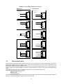
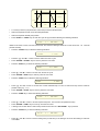
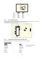
Above figure shows some examples of input/output wiring and connections.
20
Examples of input /output wiring and connections
MEASURE CH1
SIMULATION CH1
Thermocouples, mV
Thermocouples, mV
mA Active loop
+
mA Active loop
+PS
-
-
+IN
+
-IN
-
+PS
-
-IN
RTD
RTD
mA Passive Loop
mA Passive Loop
+
+PS
+
-
+IN
-
-
+PS
-
+IN
-IN
-IN
RTD
RTD
Rtd (2 wire)
Rtd (2 wire)
+PS
+PS
-
+IN
-
+IN
-IN
-IN
RTD
RTD
Rtd ( 3 wire)
Rtd ( 3 wire)
+PS
+PS
-
+IN
-
+IN
-IN
-IN
RTD
RTD
Rtd (4 wire)
Rtd (4 wire)
NOT CONNECTED
+PS
+PS
-
7.2
+IN
+IN
-
+IN
-IN
-IN
RTD
RTD
Thermocouple wires
When making measurements where additional wires have to be connected to the thermocouple leads, care must be
exercised in selecting these wire types, not only where they are claimed to be of the same composition as the
thermocouple involved, but, also, of their "quality".
Performance results where high precision is required and in circumstances where some types of thermocouple wire
leads are added to the original installation should be reviewed carefully for the impact of the choice of the additional wire
leads.
The quality of thermocouple wire is established by the limit of error to be expected with its use.
There are three recognizable levels of quality:
- Special or Premium grade
- Standard grade
- Extension wire grade
The error limits determining the grade quality differ from thermocouple type to thermocouple type, reflecting the degree of
difficulty in maintaining the precise levels of purity of the metal used.
21
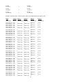
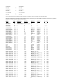
The table below summarizes the error limits for Premium and Standard grades, while Extension grade wire is
characterized by limits of error exceeding those in the table.
Errors up to ±4°C may be experienced when using Extension grade thermocouple wire for J and K thermocouples.
Limit of Error of thermocouple wires
The range indicated is the temperature limit for the indicated errors Cold junction at 0 °C
Tc
type T
T range
type E
T range
type J
T range
type K e N
T range
type R e S
T range
type B
T range
Class 1
0.5°C (-40 to +125°C)
0.004 . T (T >125°C)
-40 to +350°C
1.5°C (-40 to 375°C)
0.004.T (T >375°C)
-40 to 800°C
1.5°C (-40 to 375°C)
0.004.T (T >375°C)
-40 to 750°C
1.5°C (-40 to 375°C)
0.004.T (T >375°C)
-40 to 1000°C
1°C (0 to 1100°C)
1 + 0.003 (T-100)
(T >1100°C)
0 to 1600°C
1°C (0 to 1100°C)
1 + 0.003 (T-100)
(T >1100°C)
-----
Class 2
1°C (-40 to 133°C)
0.0075 . T (T >133 °C)
-40 to +350°C
2.5°C (-40 to 333 °C)
0.0075.T (T >333°C)
-40 to 900°C
2.5°C (-40 to 333 °C)
0.0075.T (T >333°C)
-40 to 750°C
2.5°C (-40 to 333 °C)
0.0075.T (T >333°C)
-40 to 1200°C
1.5°C (-40 to 600 °C)
0.0075.T (T >600°C)
Class 3
1°C (-67 to 40°C)
0.015. T (T <-67°C)
-200 to 40°C
2.5°C (-167 to +40°C)
0.015.T (T <-167°C)
-200°C to 40°C
2.5°C (-167 to +40°C)
0.015.T (T <-167°C)
----2.5°C (-167 to +40°C)
0.015.T (T <-167°C)
-200°C to 40°C
4°C (600 to +800°C)
0.005.T (T>800°C)
0 to 1600°C
1.5°C (-40 to 600 °C)
0.0075.T (T >600°C)
---4°C (600 to +800°C)
0.005.T (T>800°C)
600 to 1700°C
600 to 1700°C
22
8
POWER SUPPLY
8.1
Rechargeable batteries
The CL526 portable calibrator is powered by four built-in rechargeable batteries. The instrument is shipped with an
average level of charge. After unpacking, a full charge of the batteries is recommended; connect the instrument to the
charger module (“OFF” condition) for a period of 10 hours minimum.
The Ni-MH rechargeable batteries do not suffer when used in cyclic operations.
Cyclic operation is understood as a method of operation by which the battery is continually charged and discharged.
Note that a battery, at its lower limit of discharge, risks a non uniform cell polarization: this condition makes it difficult to
recharge with the charger supplied.
Avoid leaving the instrument, with batteries totally or partially discharged, for a long time without recharging.
To charge the batteries use only the original supplied charging module. The module incorporates protection and current
limiting devices not normally found in other commercial chargers.
•
When the CL526 is connected to the battery charger module, by pressing keys <SHIFT> + <BATTERY> the
following indication will be displayed:
Battery:
Line Op
If a numeric value appears, it indicates that the charger is probably faulty.
Replace the battery charger module; if the indication persists, contact OMEGA -Technical Assistance Dept.
WARNING:
AVOID USING ALKALINE BATTERIES ON AN INSTRUMENT SET FOR NI-MH RECHARGEABLE BATTERIES.
THIS IS EXTREMELY DANGEROUS AS IT COULD CAUSE THE ALKALINE BATTERIES TO EXPLODE.
8.2
Battery Charger
The external battery charger is configured, before shipment, for a supply voltage of 110-120 Vac or 220- 240 Vac, upon
order specification. The nominal voltage value is indicated on the front label of the charger. Check for the correct input
voltage before connect it to the line.
8.3
How to maximize the battery life
Disconnect the ac mains supply when the battery is charged. Use the battery until it is completely discharged.
Leaving the ac mains supply plugged in will decrease the life of the battery.
Keeping the battery terminal clean will help maximize the operating time. Periodically wipe the positive and negative
terminals with a dry cloth.
Removing and replacing the batteries will ensure electrical contact. This should be done when using a battery that has
not been used for a long time.
Note that the operating time decreases at low temperatures.
A Ni-MH battery can be recharged about 500 times when used with the recommended instructions.
When replacing the Ni-MH batteries with a new set always replace simultaneously the four pieces.
23
9
OPERATION & APPLICATIONS
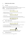
9.1
ATTENTION:
Power ON
ALL VALUES IN THE FOLLOWING FIGURES ARE ONLY LISTED AS AN EXAMPLE.
During set-up and load memory remember that the instructions of the manual related to key operation have the following
meaning:
<A> + <B>
Press the <A> key and keeping the pressure on the key, press then the <B> key.
<A> , <B>
Press in sequence, first the <A> key and then the <B> key.
•
To power the instrument press the <ON> key; the indication :
... CL526...
will appear for a few seconds.
•
The instrument runs an autodiagnostic routine for the self-checking of critical circuits and components.
•
A positive check will be shown with the indication
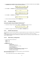
Test OK Ver 7.001
for about one second.
•
The number on the right side of the display indicates the version of the memory installed on the instrument.
•
The instrument is ready for measurement (IN mode) with the previously selected operating mode, as indicated below:
In
1280.6°C TcK:
Any faulty conditions that may be indicated are described in par. 8.9.
9.2
•
Battery voltage indication
To recall the battery voltage on the display press the <SHIFT> + <BATTERY> keys. The indication will be as
follows:
BAT 5.2 V
IIII
•
The horizontal bar indicates the level of charge of the battery (each bar is equivalent to 25% of the full capacity)
•
The “low” limit of the battery voltage, for the correct operation of the instrument, is +4.6V.
•
Press any key to reset the operative mode.
•
During normal operating modes (measure or simulation), “low battery” condition will be shown as follows:
Out 1248.3°C
TcK:
The battery symbol indicates that the battery has enough energy for about 30 minutes operation.
A black symbol means that battery charge is below minimum: batteries must be recharged.
9.3
Operating mode set up
To select the required operating mode follow the procedures indicated below.
24
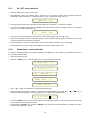
9.3.1
IN - OUT mode selection
•
Press the <ON> key to power the instrument.
•
After diagnostic routine, the calibrator will be forced into the “IN” function with the active parameter previously
selected (i.e. with the indication of a measured value of +1032 °C with thermocouple type “K”).
In
1032.2°C
TcK:
•
Open input terminals will cause a fluctuation of the reading up to “Underflow “ or “Overflow“ conditions.
•
To select the simulation mode press the <IN-OUT> key (the indication will be for example, relative to a simulated
value of 0 °C for a thermocouple type “K”).
Out
0.0°C
TcK:
•
The output value can be programmed using the two membrane slidewires (<▲> and <▼> keys).
•
Keep the key pressed to cause a continuous variation of the simulated value; the speed of variation will change by
moving the pressure to the extremity of the keys.
•
By touching a point, near the two central zones, the value will increase or decrease by one single digit.
•
Press simultaneously <▲> and <▼> cursor slidewires to set the simulated value to zero.
9.3.2
Parameter or sensor selection
To select the electrical parameter or the sensor required by the application, in any measuring or simulation mode, follow
the procedure indicated below.
•
Switch the instrument -ON-
•
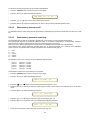
Press the <SELECT> key : the display will show one of the following menu pages:
Tc
J K T U L N E
Tc
R S B C F G D
Pt100
IEC JIS US
ni100
ni120
mV V mA
Ohm
Xscaling
•
Press <▲> or <▼> cursor slidewire to select the appropriate page.
•
Select the required parameter or sensor, by moving left or right the flashing cursor with keys <!
!> or <"
"> (eg. to
activate the thermocouple type T choose the page and cursor position as indicated below).
Tc
J K T U L N E
•
Press the <ENTER> key to memory load the selection; the instrument will return to the previous operative mode with
the new selected electrical signal or sensor.
•
By pressing the <SELECT> key, instead of <ENTER>, the instrument will not acknowledge any variation and return
to the previous parameter or sensor.
25
9.3.3
•
Tecnical unit
To change the technical unit from °C to °F (or viceversa) follow the procedure indicated below:
Instrument operative in -Out- mode as follows:
Out
0.0°C TcK:
•
Switch the instrument -OFF-
•
Keep pressed the <SELECT> key and switch the instrument <ON> obtaining the following reading:
In
10.0°F TcK:
•
Use the same procedure to return in °C switching the instrument -Off-
•
Press the <SELECT> + <ON> key to read:
In
9.3.4
-12.0°C TcK:
Decimal point position
The decimal point position, to increase or decrease the resolution upon the application, is made by pressing keys <!
!> or
<"
">.
The instrument will automatically convert values in °C or °F from decimal to integer (and viceversa) when they are in the
range limits stated in par. 1.2.1.
On mV or V mode one of the following decimal point positions can be obtained:
0.000
V
0.0
mV
0.00
mV
0.000
mV
Decimal conversion is not possible for the mA mode (always with three decimal points).
9.3.5
International Temperature Scale
The memory of the instrument stores both linearisations of the old International Practical Temperature Scale of 1968
(IPTS68) and the new International Temperature Scale of 1990 (ITS90).
The active linearisation is indicated on the right side of the display as follows:
❏
IPTS 68
■
IPTS 90
•
The change from one scale to the other is possible directly from the keyboard:
•
Press <SHIFT> + <ITS> keys
9.3.6
Rj mode
The instrument can operate with an internal automatic cold junction (Rj) compensation or a remote programmable from 50 to 100°C.
The active Rj compensation mode is indicated on the right side of the display as follows:
❏
internal automatic
■
external programmable
•
To change the reference junction (Rj) compensation mode, press <SHIFT> + <Rj> keys.
9.3.7
Convert function
The "convert" function allows readings of the electrical signal equivalent to the technical unit indication. Can be used in
both -IN- or -OUT- mode for thermocouples, resistance thermometers and x scaling.
26
•
To “convert” the type of indication, with the instrument operative in any of the above indicated modes, press <SHIFT>
+ <CONVERT> keys obtaining for example the following indications:
Out
•
•
Press <SHIFT> + <CONVERT> keys to obtain the equivalent mV indication:
Cvt
3.185
In
100.0 °C Pt
Press <SHIFT> + <CONVERT> keys to obtain:
Cvt
•
100.0 °C TcK
138.0
To return in technical unit indication press the <ENTER> key.
9.3.8
Average readings
The use of the “Average” function is advised with unstable input signals.
The average represents a progressive integration of the input signal.
•
To enable the “Average” mode press keys <SHIFT> + <AVERAGE>: the display will show:
Avg
•
128.6°C TcK :
To disable the “ Average “ function press again <SHIFT> + <AVERAGE> keys.
9.3.9
IN-OUT data memories
The availability of 60 slots of memory represents an important feature both either in simulation and/or in measurement
modes.
In the measurement mode it can be useful to store a number of input values pertinent to special test conditions.
In the simulation mode, the permanent availability of 60 calibration values can be useful, eg. during the calibration of the
scale of different recorders.
9.3.9.1
•
Data memory configuration
To store each memory slot press keys:
<SHIFT> + <0>
<SHIFT> + <1>
<SHIFT> + <2>
The following data is stored:
− operative mode
− measured or simulated value:
− decimal point position (eg. 0.1°C or 1°C)
− °C or °F technical unit
− internal or external Rj mode
− type of sensor or selected parameters: (eg thermocouple type)
− International Temperature Scale (IPTS68 or ITS90)
− 60 memory slots are available.
Memory slots are split in 20 groups each of three memories for a total of 60 memories.
Each group is identified by a letter:
group A, B, C, D, E, F, G, H, I, J, K, L, M, N, O, P, Q, R, S, T.
27
To select the required group follow the procedure indicated below:
•
Press the <SELECT> key to obtain one of the menu pages
•
Press the <0> key to obtain the following indication:
Sel STO
Group: A
•
Press the <▲> or <▼> key to select the required group number
•
Press the <0> key to confirm the selection and to return to the previously selected operative mode.
9.3.9.2
Data memory manual recall
To recall data memory values, select first the appropriate or required group number and press then the <0>, <1>, or <2>
key.
9.3.9.3
Data memory automatic scanning
The 60 stored items of data can be assigned, besides the group number, to a pre-programmed sequence.
The programmed sequence (a number of calibration points, or a number of data items to be supervised), includes a
linear sequence of memory starting from a "start" point and ending with a "end" point".
Memory for seven different pre-programmed sequences are available and the procedure is indicated below.
The numerical value and the parameter indicated below are an operative example eg. to memory load 5 calibration
points of a scale of a potentiometric recorder (temperature with a thermocouple type K).
1=
2=
3=
4=
5=
-50°C
0°C
+100°C
+200°C
+500°C
As described in par. 8.6.9.1 memory store the calibration data as follows:
point 1 =
point 2 =
point 3 =
point 4 =
point 5 =
memory 0 - group A
memory 1 - group A
memory 2 - group A
memory 0 - group B
memory 1 - group B
The simulation program set-up procedure is now required.
•
Press the <SELECT> key to obtain one of the menu pages
•
Press the <1> key to obtain the following indication:
SEL Program
# 1
•
Press the <▲
▲> and <▼
▼> keys to enter the program number required (1 to 7)
•
Press the <1> key to confirm the selection of the program number and to return to the indication of one of the menu
pages
•
Press the <2> key to obtain the following indication:
Prog #1
from A1
•
Press the <▲> and <▼> keys to select the "start" group/memory (eg. A1)
•
Press the <2> key to confirm the "start" point obtaining the following indication:
Prog #1
•
to A2
Press <s> and <t> keys to select the "end" group/memory (eg. A2)
28
•
Press the <2> key to confirm the selection and to return to the menu page
•
Press the <AUTORAMP> key to obtain one of the following indications:
Sel : Program
•
Select with <▲> and <▼> keys the required "Sel:program" page
•
Press the <AUTORAMP> key to confirm the selection and to return to the menu page
•
Press the <SELECT> key to memory load the program and to return to the operative mode
9.3.9.4
Manual step advance
To run the program with manual step advance, press the <AUTORAMP> key obtaining the following indication (as per
example indicated at par. 8.6.9.3)
.A0
-50
TcK :
The symbol on the left of the display has the following meaning:
O
=
output
I
=
input
•
Press the <AUTORAMP> key to advance one step of the program. After the "end" point (n.5 in the example - B1) the
manual sequence will start again from the point 1.
•
To go back to the previous step press <ENTER> + <AUTORAMP> keys
•
Press the <▲> or <▼> or <SELECT> or <!
!> or <"
"> key to exit the program
9.3.10
Automatic simulation cycle
The instrument can be programmed for simulating two types of pre-programmed continuous or step ramp output.
By programming the incremental steps to its minimum value (0.1 or 1 degree resolution) the step ramp can be
assimilated to a continuous ramp.
Select first the technical unit (°C or °F), the type of thermocouple and then follow the procedure indicated below.
The procedure will consider a simulation in mV.
9.3.10.1
Simulation cycle selection
Two different automatic simulations identified as "Autoramp1" and "Autoramp 2" can be memory stored.
To select the required program press the <SELECT> key to obtain one of the menu pages.
•
Press the <AUTORAMP> key to obtain one of the following indications:
Sel : Autoramp 1
Sel : Autoramp 2
•
Press the <▲> and <▼> key to select the required Autoramp program
•
Press the <AUTORAMP> key to confirm the selection and to return to the menu page indication
•
Press the <SELECT> key to return to the operative mode
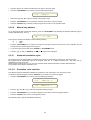
The automatic ramp cycle has the following behaviour
29
End
Z step
Start
Time
Soak
Time
Soak
•
To memory load the cycle parameters, follow the procedure indicated below
•
Select the required tecnical unit or electrical parameters
•
Select the required decimal point position
•
Press <SHIFT> + <TIME> keys to enter the cycle set-up procedure obtaining the following indication
Time
0h
0m 50s
related to the "time" in hours, minutes and seconds. The maximum setting is limited to 5 hours 33 minutes 20 seconds
(20.000 seconds)
•
Press the <START> key to obtain the following indication:
Start
0.0mV
•
Press the <▲> and <▼> cursors to set the "Start" level of the cycle
•
Press <ENTER>+<START> keys to memory store the new value
•
Press the <END> key to obtain the following indication:
End
100.0mV
•
Press <▲> and <▼> cursors to set the "end" level of the cycle
•
Press <ENTER>+<END> keys to memory store the new value
•
Press the <STEP> key to obtain the following indication:
Step
1.0mV
•
Press <▲> and <▼> cursors to set the size of each individual step. To have a continuous ramp set the minimum
possible value (e.g. = 0.1)
•
Press <ENTER>+<STEP> keys to memory store the new value
•
Press the <TIME> key to obtain the following indication:
Time
0h
0m 50s
•
Press <▲> and <▼> cursors to set the required ramp time - max. 5h-33m-20s (20000 seconds)
•
Press <ENTER>+<TIME> keys to memory store the new value
•
A setting of 0h-0m-00s allows a manual step advance each time the <AUTORAMP> key is pressed.
•
Press the <SOAK> key to read the following indication:
Soak
•
0h
0m 50s
Press <▲> and <▼> cursors to set the waiting time (or soak time). If the setting is 0h-0m-0s the waiting or soak time
is excluded
30
•
Press <ENTER>+<SOAK> keys to memory store the new value
•
Press the <MODE> key to obtain one of the following indications:
Mode 1
^ ramp
Mode 1
^ ramp
Mode 1
1 ramp
Mode +
1 ramp
•
Press the <▲> or <▼> key to select the required program type.
•
Press <ENTER> + <MODE> keys to memory store the new selection.
•
Press the <!
!> or <"
"> key to exit the set-up procedure.
9.3.10.2
single cycle program
repeated cycling program
single cycle program
repeated rise ramp program.
Simulation cycle
•
Press the <SELECT> key to obtain one of the menu pages.
•
Press the <AUTORAMP> key to obtain one of the two following indications:
Sel : Autoramp 1
Sel : Autoramp 2
•
Press <▲> or <▼> key to select the required program.
•
Press the <AUTORAMP> to memory store the selection and to return to the menu page.
•
Press the <SELECT> key to return to the normal operative mode.
•
To run the automatic simulation cycle press the <AUTORAMP> key
•
The display indicates the actual cycle position as shown below:
Prg
•
18.0mV
On the repeated cycling to stop the program press <SHIFT> + <AUTORAMP> keys.
9.3.11
Rj compensation mode check
The internal/external reference junction compensation is only enabled for temperature measurement or simulation with
thermocouples.
•
During both simulation or measuring mode to check the type of reference junction mode previously installed press the
<SELECT> key to enter the type of sensor or parameter selection menu page.
•
Press the <IN/OUT> key to obtain the following indication:
RJ :
22.8°C int
The above reading indicates that the instrument is preset with an internal automatic reference junction compensation.
The temperature indication is the value measured by the precision thin film resistance thermometer placed inside the
In/Out terminal. If, instead of the code "int" the indication
31
RJ :
0.0°C ext
is displayed, it means that an external reference junction compensation has been selected for a temperature of 0.0°C
(programmable from -50°C to +100°C).
The reference junction compensation mode can be reprogrammed as indicated in par. 8.5.6. The external reference
junction compensation value can be programmed as indicated in par. 8.5.13.2.
9.3.12
Scale factor program
The “scale factor” mode is a method to read or to simulate electrical signals values in terms of engineering units.
The example explains the procedure of installing the “scale factor” function for the calibration of a potentiometric recorder
with a scale from 0.0 mbar to 400.0 mbar corresponding to the required electrical linear input signal.
•
Press <SHIFT> + <PROGRAM X> keys to enter the "Scale Factor" set-up procedure. The display will indicate the low
end of the scale eg. in mbar.
LO:
0.0 Prog
•
Press one of the <!
!> or <"
"> keys if a decimal point shift is required.
•
Press the <▲
▲> or <▼
▼> keys to adjust to the required value.
•
Press the <ENTER> key to load in the memory the value and to advance the program one step: the display will
indicate the full scale value of the technical unit (eg. mbar).
HI:
400.0 Prog
•
Press the <▲
▲> or <▼
▼> keys to adjust the full scale value.
•
Press the <ENTER> key to load in the memory the value: the display will indicate one of the menu pages as follows:
Type : 0-1000
mV
Type :
0-100
mV
Type :
0-10
V
Type :
1-5
V
Type :
0-400
Type :
4-20
mA
Type :
0-20
mA
•
Select, through <▲
▲> or <▼
▼> keys, the required page and
•
press the <ENTER> key to memory load the needed parameter. The display will indicate one of the two following
pages:
Mode :
Linear
Mode :
Square
32
•
Press the <▲
▲> or <▼
▼> key to select the required page.
•
Press the <ENTER> key to memory load the selection.
•
The program will advance to the next step with the indication :
WORD:
!
WORD:
mbar
or from a previous set-up eg.
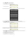
This procedure allows the setting of four alphanumeric characters as a symbol of the measured or simulated parameter.
Library of characters
..
....
..
7
8
O
P
g
!
6
9
N
Q
f
i
"
5
:
M
R
e
j
#
4
;
L
S
d
K
$
3
<
k
T
c
l
%
2
=
J
U
b
m
&
1
>
I
V
a
n
'
0
?
H
W
\
o
(
/
@
G
X
_
P
)
.
A
F
Y
^
q
*
-
B
E
Z
]
r
+
,
C
D
[
....
.....
.
.
.....
.
.
..
....
..
s
•
By pressing keys <!
!> or <"
"> the needed character, identified by being underlined, will be activated.
•
Press <▲
▲> or <▼
▼> keys to scroll the internal library of characters and symbols and select the pertinent one. (i.e. by
a proper setting you can obtain words as indicated below)
WORD:
% RH
WORD:
psi
WORD:
hPa
If the application does not require a dedicated symbol, but the display of the electrical parameter (i.e. mV, mA, Ω), recall
on the display the four blank spaces.
WORD:
_ _ _ _
•
With a random display indication remember that the four blank spaces will be settable, through single digit setting, by
pressing the <▼
▼> key on its higher side, for a few seconds.
•
Press the <ENTER> key to load in the memory the symbol.
•
The “scale factor” mode will be activated as follows:
•
Press the <SELECT> key to obtain one of the menu pages.
•
Move the flashing cursor to the “X scaling” position
33
•
Press the <ENTER> key to memory load the selection
•
The display will indicate the scaled input/output value.
Out
9.3.13
105.8 mbar
Installation parameter procedure
•
To enter this procedure press the <ENTER> + <ON> keys
•
The display will indicate as shown below (the indicated numerical value is only an example).
CAL?
•
65388
N=0
To exit from the procedure, in any of the following steps switch the instrument -Off-.
9.3.13.1
Firmware version code - Serial number
From the above step of the procedure it is possible to view the software version code .
•
Press the <IN/OUT> key to obtain the following indication:
Ver2.000
#
65535
.
The reading on the display indicates that the instrument is equipped with a memory release code 2.000.
The above information is extremely useful to understand the update status of the instrument and to simplify information
exchange with OMEGA engineers during repair or service operations.
The second number on the right side of the display is the Serial Number of the instrument.
•
Press any key to exit the procedure with the following indication:
CAL?
•
65388
N=0
Switch the instrument -OFF- to end the procedure.
9.3.13.2
External Rj compensation
To enter the External Rj compensation set-up start with the instrument switched -Off- and press <ENTER> + <ON> keys
to obtain the following indication:
CAL?
•
65388
N=0
Press the <AUTORAMP> key to obtain:
RJ :
0.0°C ext
•
Set, with <▲> and <▼> keys, the temperature of the external Rj compensation (adjustable from -50°C to +100°C).
•
Press the <AUTORAMP> key to memory load the new temperature value of reference junction compensation.
•
To end this procedure switch the instrument -Off-
34
10
DIGITAL INTERFACE
The CL526 portable calibrator is equipped with a digital interface. The interface circuit is essentially based on the serial
communication interface subsystem (SCI) on the chip of the microprocessor. The output voltage levels are TTL at 0 to +5
V.
An optional adaptor to convert the voltage level from 0 to +5V to RS232 levels can be supplied on request. This adaptor
is required to interface the CL526 with a Personal Computer.
10.1
•
Digital interface data program mode
To enter the procedure, press the <ENTER> + <ON> keys. The display will indicate:
CAL?
•
65388
N=0
To enter the program mode press the <2> key;
Baud Rate
19200
The numerical value of the “baud rate” can be one of the following : 19200, 9600, 4800, 2400, 1200, 600, 300
•
Select, with the <▲
▲> or <▼
▼> key the “baud rate” used by the receiver unit and transmission lines.
•
Press the <2> key to memory load the baud rate.
•
The display will indicate:
ID-Name :
1
The number represents the address code assigned to the instrument.
•
Press the <▲> or <▼> key to select a number from 00 to 99.
•
Press the <2> key to memory load the programmed value.
•
The display will return to the original indication:
CAL?
•
65388
N=0
To exit the procedure press the <OFF> key.
10.2
Digital output wiring practice
The wiring to the digital output signals is made through a mini DIN connector mounted on the lower end of the case.
The pertinent connections are indicated below.
Rx
Tx
ground
ground
5 V
Female miniDIN connector
(case mounted - external view)
For easy interconnections a miniDIN connector with cable (cat. EE420123) con be supplied on request. The conductors
color codes can change with different supplier; please check before using.
35
6
5
4
8
3
7
Front view
LINDY
brown
red
green
gray
purple
blue
orange
yellow
pin 1 :
pin 2 :
pin 3 :
pin 4 :
pin 5 :
pin 6 :
pin 7 :
pin 8 :
10.3
1
2
CINCH
black
green
blue
gray
yellow
white
red
brown
TTL to RS 232 adapter
The cat. BB530001 TTL to RS232 adaptor consists of a cable to which are connected a male mini DIN connector (for the
CL526) and a DB 25 connector, that contains the electrical circuitry (for the PC).
The basic circuit and connections are as follows:
TTL to RS 232 converter
+5V
10 µF, 16 V
10 µF, 16 V
+
+
6
10 µF, 16 V
IBM - PC
CL526
2 16 10
Tx
Tx
11
14
Rx
12
13
Tx
IBM
Ground
1
10 µF, 16 V +
Rx
Rx IBM
3
IBM
+
2
7
ICL 232
TSC 232
+5V
Mini-Din
3
10 µF, 16 V
D
B
2
5
4
5
15
10.4
8
Communication protocol from CL526 to a PC
The exchange of information when a CL526 is interconnected with a PC are as follows:
COMPUTER REQUEST
Computer
CL526
Tx IDNAME
Rx IDNAME
_
ß
Rx IDNAME
Tx IDNAME
Tx Instruction
Rx Instruction
_
ß
Rx Instruction
Tx Instruction
Tx char
Rx DATA 1
_
ß
Rx char
Tx DATA 1
Tx char
Rx DATA 2
_
ß
Rx char
Tx DATA 2
36
Proceed if name acknoledged
If not, do not answer
Tx char
Rx DATA 3
_
ß
Rx char
Tx DATA 3
Tx char
Rx DATA 4
_
ß
Rx char
Tx DATA 4
Tx char
Rx CHKSUM
_
ß
Rx char
Tx CHKSUM
IDNAME, Instruction, DATA 1, DATA 2, DATA 3, DATA 4 and CHKSUM are 8-bit values (1 byte)
Notes
Instruct
DATA 1
Actual value
24
STO 0 Group A
STO 0 Group A
STO 1 Group A
STO 1 Group A
STO 2 Group A
STO 2 Group A
DATA 2
DATA 3
DATA 4
display(actual) lin(actual)
Val Hi(actual)
Val Lo(actual)
164
165
165
166
166
167
x
Value Hi (0)
x
Value Hi (1)
x
Value Hi (2)
x
Value Lo (0)
x
Value Lo (1)
x
Value Lo (2)
Display (0)
x
Display (1)
x
Display (2)
x
Lin (0)
x
Lin (1)
x
Lin (2)
x
STO 0 Group B
STO 0 Group B
STO 1 Group B
STO 1 Group B
STO 2 Group B
STO 2 Group B
168
169
169
170
170
171
x
Value Hi (0)
x
Value Hi (1)
x
Value Hi (2)
x
Value Lo (0)
x
Value Lo (1)
x
Value Lo (2)
Display (0)
x
Display (1)
x
Display (2)
x
Lin (0)
x
Lin (1)
x
Lin (2)
x
STO 0 Group C
STO 0 Group C
STO 1 Group C
STO 1 Group C
STO 2 Group C
STO 2 Group C
172
173
173
174
174
175
x
Value Hi (0)
x
Value Hi (1)
x
Value Hi (2)
x
Value Lo (0)
x
Value Lo (1)
x
Value Lo (2)
Display (0)
x
Display( 1)
x
Display (2)
x
Lin (0)
x
Lin (1)
x
Lin (2)
x
STO 0 Group D
STO 0 Group D
STO 1 Group D
STO 1 Group D
STO 2 Group D
STO 2 Group D
176
177
177
178
178
179
x
Value Hi (0)
x
Value Hi (1)
x
Value Hi (2)
x
Value Lo (0)
x
Value Lo (1)
x
Value Lo (2)
Display (0)
x
Display (1)
x
Display (2)
x
Lin (0)
x
Lin (1)
x
Lin (2)
x
STO 0 Group E
STO 0 Group E
STO 1 Group E
STO 1 Group E
STO 2 Group E
STO 2 Group E
180
181
181
182
182
183
x
Value Hi (0)
x
Value Hi (1)
x
Value Hi (2)
x
Value Lo (0)
x
Value Lo (1)
x
Value Lo (2)
Display (0)
x
Display (1)
x
Display (2)
x
Lin (0)
x
Lin (1)
x
Lin (2)
x
STO 0 Group F
STO 0 Group F
STO 1 Group F
STO 1 Group F
STO 2 Group F
STO 2 Group F
184
185
185
186
186
187
x
Value Hi (0)
x
Value Hi (1)
x
Value Hi (2)
x
Value Lo (0)
x
Value Lo (1)
x
Value Lo (2)
Display (0)
x
Display (1)
x
Display (2)
x
Lin (0)
x
Lin (1)
x
Lin (2)
x
STO 0 Group G
STO 0 Group G
STO 1 Group G
STO 1 Group G
STO 2 Group G
STO 2 Group G
188
189
189
190
190
191
x
Value Hi (0)
x
Value Hi (1)
x
Value Hi (2)
x
Value Lo (0)
x
Value Lo (1)
x
Value Lo (2)
Display (0)
x
Display (1)
x
Display (2)
x
Lin (0)
x
Lin (1)
x
Lin (2)
x
STO 0 Group H
STO 0 Group H
STO 1 Group H
STO 1 Group H
192
193
193
194
x
Value Hi (0)
x
Value Hi (1)
x
Value Lo (0)
x
Value Lo (1)
Display (0)
x
Display (1)
x
Lin (0)
x
Lin (1)
x
37
STO 2 Group H 194
STO 2 Group H 195
x
Value Hi (2)
x
Value Lo (2)
Display (2)
x
Lin (2)
x
STO 0 Group I
STO 0 Group I
STO 1 Group I
STO 1 Group I
STO 2 Group I
STO 2 Group I
196
197
197
198
198
199
x
Value Hi (0)
x
Value Hi (1)
x
Value Hi (2)
x
Value Lo (0)
x
Value Lo (1)
x
Value Lo (2)
Display (0)
x
Display (1)
x
Display (2)
x
Lin (0)
x
Lin (1)
x
Lin (2)
x
STO 0 Group J
STO 0 Group J
STO 1 Group J
STO 1 Group J
STO 2 Group J
STO 2 Group J
200
201
201
202
202
203
x
Value Hi (0)
x
Value Hi (1)
x
Value Hi (2)
x
Value Lo (0)
x
Value Lo (1)
x
Value Lo (2)
Display (0)
x
Display (1)
x
Display (2)
x
Lin (0)
x
Lin (1)
x
Lin (2)
x
STO 0 Group K
STO 0 Group K
STO 1 Group K
STO 1 Group K
STO 2 Group K
STO 2 Group K
204
205
205
206
206
207
x
Value Hi (0)
x
Value Hi (1)
x
Value Hi (2)
x
Value Lo (0)
x
Value Lo (1)
x
Value Lo (2)
Display (0)
x
Display (1)
x
Display (2)
x
Lin (0)
x
Lin (1)
x
Lin (2)
x
STO 0 Group L
STO 0 Group L
STO 1 Group L
STO 1 Group L
STO 2 Group L
STO 2 Group L
208
209
209
210
210
211
x
Value Hi (0)
x
Value Hi (1)
x
Value Hi (2)
x
Value Lo (0)
x
Value Lo (1)
x
Value Lo (2)
Display (0)
x
Display (1)
x
Display (2)
x
Lin (0)
x
Lin (1)
x
Lin (2)
x
STO 0 Group M
STO 0 Group M
STO 1 Group M
STO 1 Group M
STO 2 Group M
STO 2 Group M
212
213
213
214
214
215
x
Value Hi (0)
x
Value Hi (1)
x
Value Hi (2)
x
Value Lo (0)
x
Value Lo (1)
x
Value Lo (2)
Display (0)
x
Display (1)
x
Display (2)
x
Lin (0)
x
Lin (1)
x
Lin (2)
x
STO 0 Group N
STO 0 Group N
STO 1 Group N
STO 1 Group N
STO 2 Group N
STO 2 Group N
216
217
217
218
21£
219
x
Value Hi (0)
x
Value Hi (1)
x
Value Hi (2)
x
Value Lo (0)
x
Value Lo (1)
x
Value Lo (2)
Display (0)
x
Display (1)
x
Display (2)
x
Lin (0)
x
Lin (1)
x
Lin (2)
x
STO 0 Group O
STO 0 Group O
STO 1 Group O
STO 1 Group O
STO 2 Group O
STO 2 Group O
220
221
221
222
222
223
x
Value Hi (0)
x
Value Hi (1)
x
Value Hi (2)
x
Value Lo (0)
x
Value Lo (1)
x
Value Lo (2)
Display (0)
x
Display (1)
x
Display (2)
x
Lin (0)
x
Lin (1)
x
Lin (2)
x
STO 0 Group P
STO 0 Group P
STO 1 Group P
STO 1 Group P
STO 2 Group P
STO 2 Group P
224
225
225
226
226
227
x
Value Hi (0)
x
Value Hi (1)
x
Value Hi (2)
x
Value Lo (0)
x
Value Lo (1)
x
Value Lo (2)
Display (0)
x
Display (1)
x
Display (2)
x
Lin (0)
x
Lin (1)
x
Lin (2)
x
STO 0 Group Q
STO 0 Group Q
STO 1 Group Q
STO 1 Group Q
STO 2 Group Q
STO 2 Group Q
228
229
229
230
230
231
x
Value Hi (0)
x
Value Hi (1)
x
Value Hi (2)
x
Value Lo (0)
x
Value Lo (1)
x
Value Lo (2)
Display (0)
x
Display (1)
x
Display (2)
x
Lin (0)
x
Lin (1)
x
Lin (2)
x
STO 0 Group R
STO 0 Group R
STO 1 Group R
STO 1 Group R
232
233
233
234
x
Value Hi (0)
x
Value Hi (1)
x
Value Lo (0)
x
Value Lo (1)
Display (0)
x
Display (1)
x
Lin (0)
x
Lin (1)
x
38
STO 2 Group R 234
STO 2 Group R 235
x
Value Hi (2)
x
Value Lo (2)
Display (2)
x
Lin (2)
x
STO 0 Group S
STO 0 Group S
STO 1 Group S
STO 1 Group S
STO 2 Group S
STO 2 Group S
236
237
237
238
238
239
x
Value Hi (0)
x
Value Hi (1)
x
Value Hi (2)
x
Value Lo (0)
x
Value Lo (1)
x
Value Lo (2)
Display (0)
x
Display (1)
x
Display (2)
x
Lin (0)
x
Lin (1)
x
Lin (2)
x
STO 0 Group T
STO 0 Group T
STO 1 Group T
STO 1 Group T
STO 2 Group T
STO 2 Group T
240
241
241
242
242
243
x
Value Hi (0)
x
Value Hi (1)
x
Value Hi (2)
x
Value Lo (0)
x
Value Lo (1)
x
Value Lo (2)
Display (0)
x
Display(1)
x
Display (2)
x
Lin (0)
x
Lin(1)
x
Lin (2)
x
RAMP 1
RAMP 1
RAMP 1
RAMP 1
128
129
130
131
x
Start Hi (1)
Step Hi (1)
Soak Hi (1)
x
Start Lo (1)
Step Lo (1)
Soak Lo (1)
Time Hi (1)
Stop Hi (1)
Lin (1)
x
Time Lo (1)
Stop Lo (1)
Display (1)
Mode (1)
RAMP 2
RAMP 2
RAMP 2
RAMP 2
132
133
134
135
x
Start Hi (2)
Step Hi (2)
Soak Hi (2)
x
Start Lo (2)
Step Lo (2)
Soak Lo (2)
Time Hi (2)
Stop Hi (2)
Lin (2)
x
Time Lo (2)
Stop Lo (2)
Display (2)
Mode (2)
X SCALING
X SCALING
X SCALING
X SCALING
136
137
138
139
x
HiX Hi
Mode X
CHAR 4
x
HiX Lo
CHAR 1
x
LOX Hi
Decimal point
CHAR 2
x
LOX Lo
Type X
CHAR 3
x
VARIE
VARIE
VARIE
141
248
32
x
x
Vbat
STO group
x
x
x
Program
x
x
Ramp
x
PROGRAM
PROGRAM
PROGRAM
PROGRAM
244
245
246
247
x
From (Prog 2)
From (Prog 4)
From (Prog 6)
x
to (Prog 2)
to (Prog 4)
to (Prog 6)
From
From
From
From
to (Prog 1)
to (Prog 3)
to (Prog 5)
to (Prog 7)
display (name).AND.10hex=
0
10hex
= Rj int
= Rj ext
display (name).AND.8 =
0
8
= ITS68
= ITS90
display (name).AND.07hex =
0
1
2
3
4
=
=
=
=
=
display (name.AND.40hex =
0
40hex
= °C
= °F
display (name).AND.20hex =
0
20hex
= IN
= OUT
lin (name)
0
1
2
3
4
5
6
7
8
9
10
11
12
13
14
15
16
17
=
=
=
=
=
=
=
=
=
=
=
=
=
=
=
=
=
=
1.9999
19.999
199.99
1999.9
19999
Tc J
Tc K
Tc T
Tc U
Tc L
Tc N
Tc E
Tc R
Tc S
Tc B
Tc C
Tc F
Tc G
Tc D
Pt100 (.385)
Pt100 (.3916 JIS)
Pt100 (.3910 OIML)
Ni100
39
(Prog 1)
(Prog 3)
(Prog 5)
(Prog 7)
18
19
20
21
22
23
24
25
=
=
=
=
=
=
=
=
Ni120
OHM
22 mV
100 mV
1000 mV
10 V
20 mA
X scaling
Lin (name).AND.80hex =
0
80hex
= value OK
= error
if line (name).AND.80hex = 80hex
corresponding "Value Lo"
0
1
2
3
4
6
=
=
=
=
=
=
under
over
error 7
error 2
error 6
error 0
if line (name).AND.80hex = 0
value (name) = 2nd complement (16 bit) Value Hi (name).256 + Value Lo (name)
Mode =
0
1
2
3
=
=
=
=
one ramp dual slope
multi ramp dual slope
one step one slope
multi ramp one slope
Type X
0
1
3
4
5
6
=
=
=
=
=
=
0
0
4
0
1
0
Mode X
0
1
= linear
= square
STO Group selected
0
1
2
...
n (max. 19)
=
=
=
=
=
A
B
C
...
n (max. T)
Program
0
1
...
n (max. 7)
=
=
=
=
Program 1
Program 2
...
n (max. Program 7)
Ramp
0
1
2
= Autoramp 1
= Autoramp 2
= Program
From........To........
0
1
2
3
...
n (max. 59)
=
=
=
=
=
=
Volt Vbat
-
100 mV
1000 mV
20 mA
400 _
5V
10 V
STO 0 Group A
STO 1 Group A
STO 2 Group A
STO 0 Group B
...
STO n Group n (max. STO 2 Group T)
= (Vbat x 2) / 51
CHKSUM ( checksum ) = DATA1 + DATA2 + DATA3 + DATA4).AND. FF
The above is useful to verify the integrity of transmitted and received data
The minimum time-out of the CL526 is 5 seconds.
10.5
Computer request for CL526 settings
Computer
CL526
Tx IDNAME
Rx IDNAME
_
ß
Rx IDNAME
Tx IDNAME
Tx Instruction
Rx Instruction
_
ß
Rx Instruction
Tx Instruction
Tx DATA 1
Rx char
_
ß
Rx DATA 1
Tx char
Tx DATA 2
Rx char
_
ß
Rx DATA 2
Tx char
Proceed if name acknoledged
If not, do not answer
40
Tx DATA 3
Rx char
_
ß
Rx DATA 3
Tx char
Tx DATA 4
Rx char
_
ß
Rx DATA 4
Tx char
Tx CHKSUM
Rx char
_
ß
Rx CHKSUM
Tx char
The CL526 receives and verifies CHKSUM; when not valid, it does not accept the transmitted data
Each PC instruction for operative mode request must be followed by the CHECSUM recalculation Instruction 47 (with the
pertinent A and B values) as per the table below
Notes
Set In
Set display
Set value
Start ramp
Start ramp
Instr
25
26
27
28
33
DATA 1
Lin (actual)
Display (actual)
Value Hi (Out)
x
x
DATA 2
x
x
Value Lo (Out)
x
x
DATA 3
x
x
x
x
x
DATA 4
x
x
x
x
x
A
B
-----------------------------------------
TIME RAMP 1
START RAMP 1
STOP RAMP 1
STEP RAMP 1
Lin/Dis RAMP 1
SOAK RAMP 1
MODE RAMP 1
127
127
127
127
127
127
127
0
0
0
0
0
0
0
2
4
6
8
10
12
14
Time Hi
Start Hi
Stop Hi
Step Hi
Lin
Soak Hi
0
Time Lo
Start Lo
Stop Lo
Step Lo
Display
Soak Lo
Mode
0
0
0
0
0
0
0
0
0
0
0
0
0
0
TIME RAMP 2
START RAMP 2
STOP RAMP 2
STEP RAMP 2
Lin/Dis RAMP 2
SOAK RAMP 2
MODE RAMP 2
127
127
127
127
127
127
127
0
0
0
0
0
0
0
18
20
22
24
26
28
30
Time Hi
Start Hi
Stop Hi
Step Hi
Lin
Soak Hi
0
Time Lo
Start Lo
Stop Lo
Step Lo
Display
Soak Lo
Mode
0
0
0
0
0
0
0
16
16
16
16
16
16
16
LoX
HiX
DP/TYPE
MODE/Char 1
Char 1/Char 2
Char 3/Char 4
127
127
127
127
127
127
0
0
0
0
0
0
34
36
38
40
41
43
LoX Hi
HiX Lo
DP
MODE
Char 1
Char 3
LoX Hi
HiX Lo
TYPE
Char 1
Char 2
Char 4
0
0
0
0
0
0
32
32
32
32
32
32
Dis/Lin STO 0 #A
Value STO 0 #A
Dis/Lin STO1 #A
Value STO 1 #A
Dis/Lin STO 2 #A
Value STO 2 #A
127
127
127
127
127
127
0
0
0
0
0
0
146
148
150
152
154
156
Display (0)
Value Hi (0)
Dispaly (1)
Value Hi (1)
Display (2)
Value Hi (2)
Lin
Value Lo (0)
Lin
Value Lo (1)
Lin
Value Lo (2)
0
0
0
0
0
0
144
144
144
144
144
144
Dis/Lin STO 0 #B
Value STO 0 #B
Dis/Lin STO1 #B
Value STO 1 #B
Dis/Lin STO 2 #B
Value STO 2 #B
127
127
127
127
127
127
0
0
0
0
0
0
162
164
166
168
170
172
Display (0)
Value Hi (0)
Dispaly (1)
Value Hi (1)
Display (2)
Value Hi (2)
Lin
Value Lo (0)
Lin
Value Lo (1)
Lin
Value Lo (2)
0
0
0
0
0
0
160
160
160
160
160
160
Dis/Lin STO 0 #C
Value STO 0 #C
Dis/Lin STO 1 #C
Value STO 1 #C
Dis/Lin STO 2 #C
Value STO 2 #C
127
127
127
127
127
127
0
0
0
0
0
0
178
180
182
184
186
188
Display (0)
Value Hi (0)
Dispaly (1)
Value Hi (1)
Display (2)
Value Hi (2)
Lin
Value Lo (0)
Lin
Value Lo (1)
Lin
Value Lo (2)
0
0
0
0
0
0
176
176
176
176
176
176
Dis/Lin STO 0 #D
Value STO 0 #D
Dis/Lin STO 1 #D
Value STO 1 #D
127
127
127
127
0
0
0
0
194
196
198
200
Display (0)
Value Hi (0)
Dispaly (1)
Value Hi (1)
Lin
Value Lo (0)
Lin
Value Lo (1)
0
0
0
0
192
192
192
192
41
Dis/Lin STO 2 #D 127
Value STO 2 #D 127
0
0
202
204
Display (2) Lin
Value Hi (2) Value Lo (2)
0
0
192
192
Dis/Lin STO 0 #E
Value STO 0 #E
Dis/Lin STO 1 #E
Value STO 1 #E
Dis/Lin STO 2 #E
Value STO 2 #E
127
127
127
127
127
127
0
0
0
0
0
0
210
212
214
216
218
220
Display (0)
Value Hi (0)
Dispaly (1)
Value Hi (1)
Display (2)
Value Hi (2)
Lin
Value Lo (0)
Lin
Value Lo (1)
Lin
Value Lo (2)
0
0
0
0
0
0
208
208
208
208
208
208
Dis/Lin STO 0 #F
Value STO 0 #F
Dis/Lin STO 1 #F
Value STO 1 #F
Dis/Lin STO 2 #F
Value STO 2 #F
127
127
127
127
127
127
0
0
0
0
0
0
226
228
230
232
234
236
Display (0)
Value Hi (0)
Dispaly (1)
Value Hi (1)
Display (2)
Value Hi (2)
Lin
Value Lo (0)
Lin
Value Lo (1)
Lin
Value Lo (2)
0
0
0
0
0
0
224
224
224
224
224
224
Dis/Lin STO 0 ##
Value STO 0 ##
Dis/Lin STO 1 ##
Value STO 1 ##
Dis/Lin STO 2 ##
Value STO 2 ##
127
127
127
127
127
127
0
0
0
0
0
0
242
244
246
248
250
252
Display (0)
Value Hi (0)
Dispaly (1)
Value Hi (1)
Display (2)
Value Hi (2)
Lin
Value Lo (0)
Lin
Value Lo (1)
Lin
Value Lo (2)
0
0
0
0
0
0
240
240
240
240
240
240
Dis/Lin STO 0 #H
Value STO 0 #H
Dis/Lin STO 1 #H
Value STO 1 #H
Dis/Lin STO 2 #H
Value STO 2 #H
127
127
127
127
127
127
1
1
1
1
1
1
2
4
6
8
10
12
Display (0)
Value Hi (0)
Dispaly (1)
Value Hi (1)
Display (2)
Value Hi (2)
Lin
Value Lo (0)
Lin
Value Lo (1)
Lin
Value Lo (2)
1
1
1
1
1
1
0
0
0
0
0
0
Dis/Lin STO 0 #I
Value STO 0 #I
Dis/Lin STO 1 #I
Value STO 1 #I
Dis/Lin STO 2 #I
Value STO 2 #I
127
127
127
127
127
127
1
1
1
1
1
1
18
20
22
24
26
28
Display (0)
Value Hi (0)
Dispaly (1)
Value Hi (1)
Display (2)
Value Hi (2)
Lin
Value Lo (0)
Lin
Value Lo (1)
Lin
Value Lo (2)
1
1
1
1
1
1
16
16
16
16
16
16
Dis/Lin STO 0 #J
Value STO 0 #J
Dis/Lin STO 1 #J
Value STO 1 #J
Dis/Lin STO 2 #J
Value STO 2 #J
127
127
127
127
127
127
1
1
1
1
1
1
34
36
38
40
42
44
Display (0)
Value Hi (0)
Dispaly (1)
Value Hi (1)
Display (2)
Value Hi (2)
Lin
Value Lo (0)
Lin
Value Lo (1)
Lin
Value Lo (2)
1
1
1
1
1
1
32
32
32
32
32
32
Dis/Lin STO 0 #K
Value STO 0 #K
Dis/Lin STO 1 #K
Value STO 1 #K
Dis/Lin STO 2 #K
Value STO 2 #K
127
127
127
127
127
127
1
1
1
1
1
1
50
52
54
56
58
60
Display (0)
Value Hi (0)
Dispaly (1)
Value Hi (1)
Display (2)
Value Hi (2)
Lin
Value Lo (0)
Lin
Value Lo (1)
Lin
Value Lo (2)
1
1
1
1
1
1
48
48
48
48
48
48
Dis/Lin STO 0 #L
Value STO 0 #L
Dis/Lin STO 1 #L
Value STO 1 #L
Dis/Lin STO 2 #L
Value STO 2 #L
127
127
127
127
127
127
1
1
1
1
1
1
66
68
70
72
74
76
Display (0)
Value Hi (0)
Dispaly (1)
Value Hi (1)
Display (2)
Value Hi (2)
Lin
Value Lo (0)
Lin
Value Lo (1)
Lin
Value Lo (2)
1
1
1
1
1
1
64
64
64
64
64
64
Dis/Lin STO 0 #M
Value STO 0 #M
Dis/Lin STO 1 #M
Value STO 1 #M
Dis/Lin STO 2 #M
Value STO 2 #M
127
127
127
127
127
127
1
1
1
1
1
1
82
84
86
88
90
92
Display (0)
Value Hi (0)
Dispaly (1)
Value Hi (1)
Display (2)
Value Hi (2)
Lin
Value Lo (0)
Lin
Value Lo (1)
Lin
Value Lo (2)
1
1
1
1
1
1
80
80
80
80
80
80
Dis/Lin STO 0 #N
Value STO 0 #N
Dis/Lin STO 1 #N
Value STO 1 #N
127
127
127
127
1
1
1
1
98
100
102
104
Display (0)
Value Hi (0)
Dispaly (1)
Value Hi (1)
Lin
Value Lo (0)
Lin
Value Lo (1)
1
1
1
1
96
96
96
96
42
Dis/Lin STO 2 #N 127
Value STO 2 #N 127
1
1
106
108
Display (2) Lin
Value Hi (2) Value Lo (2)
1
1
96
96
Dis/Lin STO 0 #O
Value STO 0 #O
Dis/Lin STO 1 #O
Value STO 1 #O
Dis/Lin STO 2 #O
Value STO 2 #O
127
127
127
127
127
127
1
1
1
1
1
1
114
116
118
120
122
124
Display (0)
Value Hi (0)
Dispaly (1)
Value Hi (1)
Display (2)
Value Hi (2)
Lin
Value Lo (0)
Lin
Value Lo (1)
Lin
Value Lo (2)
1
1
1
1
1
1
112
112
112
112
112
112
Dis/Lin STO 0 #P
Value STO 0 #P
Dis/Lin STO 1 #P
Value STO 1 #P
Dis/Lin STO 2 #P
Value STO 2 #P
127
127
127
127
127
127
1
1
1
1
1
1
130
132
134
136
138
140
Display (0)
Value Hi (0)
Dispaly (1)
Value Hi (1)
Display (2)
Value Hi (2)
Lin
Value Lo (0)
Lin
Value Lo (1)
Lin
Value Lo (2)
1
1
1
1
1
1
128
128
128
128
128
128
Dis/Lin STO 0 #Q
Value STO 0 #Q
Dis/Lin STO 1 #Q
Value STO 1 #Q
Dis/Lin STO 2 #Q
Value STO 2 #Q
127
127
127
127
127
127
1
1
1
1
1
1
146
148
150
152
154
156
Display (0)
Value Hi (0)
Dispaly (1)
Value Hi (1)
Display (2)
Value Hi (2)
Lin
Value Lo (0)
Lin
Value Lo (1)
Lin
Value Lo (2)
1
1
1
1
1
1
144
144
144
144
144
144
Dis/Lin STO 0 #R
Value STO 0 #R
Dis/Lin STO 1 #R
Value STO 1 #R
Dis/Lin STO 2 #R
Value STO 2 #R
127
127
127
127
127
127
1
1
1
1
1
1
162
164
166
168
170
172
Display (0)
Value Hi (0)
Dispaly (1)
Value Hi (1)
Display (2)
Value Hi (2)
Lin
Value Lo (0)
Lin
Value Lo (1)
Lin
Value Lo (2)
1
1
1
1
1
1
160
160
160
160
160
160
Dis/Lin STO 0 #S
Value STO 0 #S
Dis/Lin STO 1 #S
Value STO 1 #S
Dis/Lin STO 2 #S
Value STO 2 #S
127
127
127
127
127
127
1
1
1
1
1
1
178
180
182
184
186
188
Display (0)
Value Hi (0)
Dispaly (1)
Value Hi (1)
Display (2)
Value Hi (2)
Lin
Value Lo (0)
Lin
Value Lo (1)
Lin
Value Lo (2)
1
1
1
1
1
1
176
176
176
176
176
176
Dis/Lin STO 0 #T
Value STO 0 #T
Dis/Lin STO 1 #T
Value STO 1 #T
Dis/Lin STO 2 #T
Value STO 2 #T
127
127
127
127
127
127
1
1
1
1
1
1
194
196
198
200
202
204
Display (0)
Value Hi (0)
Dispaly (1)
Value Hi (1)
Display (2)
Value Hi (2)
Lin
Value Lo (0)
Lin
Value Lo (1)
Lin
Value Lo (2)
1
1
1
1
1
1
192
192
192
192
192
192
Notes
CHKSUM recalc.
Instr DATA 1
47
A
DATA 2
B
DATA 3
0
DATA 4
0
A
B
-----------
From/To PROG 1
From/To PROG 2
From/To PROG 3
From/To PROG 4
From/To PROG 5
From/To PROG 6
From/To PROG 7
127
127
127
127
127
127
127
1
1
1
1
1
1
1
210
212
214
216
218
220
222
From
From
From
From
From
From
From
To
To
To
To
To
To
To
1
1
1
1
1
1
1
PROGRAM
RAMP
Group
0
0
0
0
0
0
0
0
0
-------------------------------
PROGRAM
72
RAMP
71
SELECT GROUP 74
The computer must split a 16 bit word into 2 words of 8 bit as follows
Value Hi ( .... )
Higher 8 bit
CHKSUM =
Value Lo ( .... )
Lower 8 bit
(DATA1 + DATA2 + DATA 3 + DATA 4) .AND.7F
43
208
208
208
208
208
208
208
10.6
Communication programs
In this paragraph are illustrated two examples of communication programs between the CL526 and an IBM or IBM
compatible PC.
Example A: (data transfer from CL526 to PC)
Set IDNAME=1 and BAUD RATE=9600 on CL526 (see chapter 8.6). Connect CL526 through adapter BB530001 (TTLRS232 converter), to personal computer communication port COM1.
Set CL526 in mA measurement (IN). Run the program and you will see on the computer screen the actual reading value
(once).
Example B: (PC instructions to CL526)
Set IDNAME=1 and BAUD RATE=9600 on CL526 (see chapter 8.6). Connect CL526 through adapter BB530001 (TTLRS232 converter), to personal computer communication port COM1.
Set the CL526 for current OUT mode; run the program and CL526 will be set automatically to 20mA.
Example A:
1Ø CHAR = Ø
2Ø IDNAME = 1
3Ø INSTRUCTION = 24
35 OPEN "COM1: 96ØØ, N,8,1,CD,CS,DS,RS" FOR RANDOM AS # 1
4Ø PRINT #1, CHR$ (IDNAME);:REM TRANSMIT IDNAME TO CL526
5Ø WHILE LOC (1) = Ø: WEND: REM WAIT RECEIVING IDNAME FROM CL526
6Ø IDNAME = ASC (INPUT$ (1, 1)): REM READ RECEIVED IDNAME FROM CL526
7Ø PRINT #1, CHR$ (INSTRUCTION);
8Ø WHILE LOC (1) = Ø: WEND
9Ø INSTRUCTION = ASC (INPUT$ (1, 1))
1ØØ PRINT #1, CHR$ (CHAR);
11Ø WHILE LOC (1) = Ø: WEND
12Ø DATA 1 = ASC (INPUT$ (1, 1))
13Ø PRINT #1, CHR$ (CHAR);
14Ø WHILE LOC (1) = Ø: WEND
15Ø DATA 2 = ASC (INPUT$ (1, 1))
16Ø PRINT #1, CHR$ (CHAR);
17Ø WHILE LOC (1) = Ø: WEND
18Ø DATA 3 = ASC (INPUT$ (1, 1))
19Ø PRINT #1, CHR$ (CHAR);
2ØØ WHILE LOC (1) = Ø: WEND
21Ø DATA 4 = ASC (INPUT$ (1, 1))
22Ø PRINT #1, CHR$ (CHAR);
231Ø WHILE LOC (1) = Ø: WEND
24Ø CHKSUM = ASC (INPUT$ (1, 1))
25Ø IF CHKSUM <> ((DATA1 + DATA2 + DATA3 + DATA4) AND &HFF) THEN PRINT "Error": END
26Ø VALUE = DATA3 * 256 + DATA4
27Ø IF VALUE > 32767 THEN VALUE =VALUE - 65536: REM 2'S COMPLEMENT
28Ø PRINT "VALUE: " ; VALUE / 1ØØ
29Ø END
Example B:
1Ø CHAR = Ø
2Ø IDNAME = 1
3Ø INSTRUCTION = 27
4Ø VALUE = 2ØØØ
5Ø VALUE$ = HEX$ (VALUE)
55 WHILE LEN (VALUE$)<4: VALUE$ ="Ø"+VALUE$: WEND
6Ø IF LEN (VALUE$) > 4 THEN VALUE$ =RIGHT$ (VALUE$,4)
65 DATA1 = VAL ("&H" + LEFT$ (VALUE$, 2))
7Ø DATA2 = VAL ("&H" +RIGHT$ (VALUE$, 2))
75 DATA3 = Ø
8Ø DATA4 = Ø
9Ø CHKSUM = (DATA1 + DATA2 + DATA3 + DATA4) AND &H7F
1ØØ REM MEMORY RELEASE PREVIOUS 4.xx1 (Example 4.ØØØ, 4.2ØØ) MUST USE
11Ø REM NEXT LINE INSTEAD LINE 9Ø OR PROGRAM DOES'NT WORK
12Ø REM CHKSUM =(DATA1 + DATA2 + DATA3 + DATA4) AND &HFF
13Ø OPEN "COM1: 96ØØ,N,8,1,CD,CS,DS,RS" FOR RANDOM AS #1
14Ø PRINT #1, CHR$ (IDNAME) ; : REM TRANSMIT IDNAME TO CL526
15Ø WHILE LOC (1) = Ø: WEND: REM WAIT RECEIVING IDNAME FROM CL526
44
16Ø IDNAME = ASC (INPUT$ (1 , 1)): REM READ RECEIVED IDNAME FROM CL526
17Ø PRINT #1, CHR$ (INSTRUCTION) ;
18Ø WHILE LOC (1) = Ø : WEND
19Ø INSTRUCTION = ASC (INPUT$ (1 , 1))
2ØØ PRINT #1, CHR$ (DATA1) ;
21Ø WHILE LOC (1) = Ø : WEND
22Ø CHAR = ASC (INPUT$ (1 , 1))
23Ø PRINT #1, CHR$ (DATA2) ;
24Ø WHILE LOC (1) = Ø : WEND
25Ø CHAR = ASC (INPUT$ (1 , 1))
26Ø PRINT #1, CHR$ (DATA3) ;
27Ø WHILE LOC (1) = Ø : WEND
28Ø CHAR = ASC (INPUT$ (1 , 1))
29Ø PRINT #1, CHR$ (DATA4) ;
3ØØ WHILE LOC (1) = Ø : WEND
31Ø CHAR = ASC (INPUT$ (1 , 1))
32Ø PRINT #1, CHR$ (CHKSUM) ;
33Ø WHILE LOC (1) = Ø : WEND
34Ø CHAR = ASC (INPUT$ (1 , 1))
35Ø PRINT "Trasmitted."
39Ø END
45
11
MAINTENANCE
The CL526 portable calibrator has been factory tested and calibrated before shipment.
The calibration should be verified and re-adjusted if the instrument is showing an error exceeding the declared
specifications or when a critical active or passive component is replaced (either at component level or at board level).
OMEGA will supply, on request, a technical reference manual, with all instructions and recommendations for service and
calibration. OMEGA engineers will give prompt support for any requests of assistance.
11.1
Safety recommendations
Primary elements (i.e. thermocouples, resistance thermometers, etc.) are normally linked to electrical potentials equal or
near to the ground potential. However, in some applications, there may be present a common mode voltage to earth.
Check for voltage between input terminals and ground, as this voltage can be transmitted to other devices connected to
the calibrator.
11.2
Faulty operating conditions
During start up, measuring and simulation modes, faulty conditions of the instrument will be announced, with coded
messages as follows:
Indicates a possible loss of data on “AUTORAMP” program or
on the manual memories.
Error
Checksum 1
Error
Checksum 2
Error
Checksum 3
Error
Checksum 4
Error
Checksum 5
Indicates a possible loss of calibration data,
“AUTORAMP” data and/or on the manual memories
Error
Checksum 6
Indicates a possible loss of calibration data, and/or “PROGRAM
X”data.
Error
Checksum 7
Indicates a possible loss of calibration data, and/or
“AUTORAMP” data, “Xscaling” and from the three manual
memories
!!!
ERROR 9
!!!
Indicates a possible loss of data on “PROGRAM X”.
Indicates a possible loss of data on “AUTORAMP”, “PROGRAM
X” and/or on the manual memories.
Indicates a possible loss of calibration data.
and/or
Indicates a data writing on the EEPROM memory not verified.
When the above error codes are indicated repeat the set-up of the application parameters and/or autoramp data and/or
In-Out memories.
+
UNDER
-
OVER
+
ERROR 2
Indicates “underflow” conditions
Indicates “overflow” conditions
Indicates an environment temperature (in correspondence with
<IN/OUT> terminals) exceeding the stated limits
Indicates that the load is exceeding the stated limits.
When in mA “OUT” function, the external load must not exceed
1000 Ω.
46
ERROR 6
ERROR 7
When in mV or Tc “OUT” function the current flow must not
exceed 0.5 mA.
Indicates a possible error during scale factor computation.
The above indicated faulty conditions can be announced both during the autodiagnostic routine or in measure or
simulation modes.
If the faulty condition is critical for the type of application, it is recommended to re-run the pertinent set up procedure.
11.3
Protection fuses
The CL526 unit, is protected against overvoltage and overcurrent inputs, by thermal fuses. When they activate, you
should disconnect the electrical connections from the unit and switch the instrument off for about 2 minutes. The thermal
fuses will be automatically restored and you can resume your work.
11.4
Storage
If the instrument is left unused for a long time, it is recommended to remove the batteries.
Store the instrument in the original package, at a temperature from -30°C to +60°C, with R.H. less than 90%.
If the instrument has been unused for a month check the battery voltage, and charge the Ni-MH batteries for at least 12
hours.
47
INDEX
A
K
Automatic simulation cycle; 29
Average measurements; 10
Average readings; 27
Keyboard; 10; 13
M
MAINTENANCE; 46
Manual step advance; 29
Microprocessor; 15
B
Battery Charger; 23
Battery charger. Operation from line source; 16
Battery voltage indication; 24
O
Operating mode set up; 24
OPERATION & APPLICATIONS; 24
C
Case; 11
Communication programs; 44
Communication protocol from CL526 to a PC; 36
Computer request for CL526 settings; 40
CONTENTS; 4
Convert function; 26
P
Parameter or sensor selection; 25
PHYSICAL DESCRIPTION; 12
Power ON; 24
Power supply; 13
POWER SUPPLY; 23
PRE-OPERATIONAL CHECK; 19
Protection fuses; 47
D
D/A converter; 15
Data memory automatic scanning; 28
Data memory configuration; 27
Data memory manual recall; 28
Decimal point position; 26
Digital display; 15
Digital interface; 10; 16; 35
Digital interface data program mode; 35
Digital output wiring practice; 35
Display; 10
R
Rechargeable batteries; 23
Resistance and Rtd measurements; 16
Resistance and Rtd simulation; 17
Rj compensation mode check; 31
Rj mode; 26
S
E
Safety recommendations; 46
Scale factor function; 10
Scale factor program; 32
Self calibration; 10
Simulation cycle; 31
Simulation cycle selection; 29
Simulation programs; 10
Specifications; 7
Square root function; 10
Storage; 47
ELECTRICAL CONNECTIONS; 20
F
Faulty operating conditions; 46
Firmware; 15
Firmware version code - Serial number; 34
FUNCTIONAL DESCRIPTION; 13
G
T
GENERAL FEATURES; 10
GENERAL PERFORMANCE; 6
Table of ranges and accuracies; 9
Tecnical unit; 26
Thermocouple wires; 21
Thermocouples input-output circuit; 17
TTL to RS 232 adaptor; 36
I
IN - OUT mode selection; 25
Increase the life of the battery; 23
INDEX; 48
IN-OUT data memories; 27
Input and output flexibility; 10
Input circuit; 14
Installation parameter procedure; 34
International Temperature Scale; 26
INTRODUCTORY NOTE; 3
U
UNPACKING; 18
W
Wiring practice; 20
48
WARRANTY/DISCLAIMER
OMEGA ENGINEERING, INC. warrants this unit to be free of defects in materials and workmanship for a period of 13
months from date of purchase. OMEGA Warranty adds an additional one (1) month grace period to the normal one (1)
year product warranty to cover handling and shipping time. This ensures that OMEGA’s customers receive maximum
coverage on each product.
If the unit should malfunction, it must be returned to the factory for evaluation. OMEGA’s Customer Service Department
will issue an Authorized Return (AR) number immediately upon phone or written request. Upon examination by OMEGA,
if the unit is found to be defective it will be repaired or replaced at no charge. OMEGA’s WARRANTY does not apply to
defects resulting from any action of the purchaser, including but not limited to mishandling, improper interfacing,
operation outside of design limits, improper repair, or unauthorized modification. This WARRANTY is VOID if the unit
shows evidence of having been tampered with or shows evidence of being damaged as a result of excessive corrosion;
or current, heat, moisture or vibration; improper specification; misapplication; misuse or other operating conditions
outside of OMEGA’s control. Components which wear are not warranted, including but not limited to contact points,
fuses, and triacs.
OMEGA is pleased to offer suggestions on the use of its various products However, OMEGA neither assumes
responsibility for any omissions or errors nor assumes liability for any damages that result from the use of its
products in accordance with information provided by OMEGA, either verbal or written. OMEGA warrants only
that the parts manufactured by it will be as specified and free of defects. OMEGA MAKES NO OTHER WARRANTIES OR REPRESENTATIONS OF ANY KIND WHATSOEVER, EXPRESSEO OR IMPUED, EXCEPT THAT OF
TITLE, AND ALL IMPLIED WARRANTlES INCLUDING ANY WARRANTY OF MERCHANTABIUTY AND RTNESS
FOR A PARTlCULAR PURPOSE ARE HEREBY DISCLAIMED. LIMITATlON OF LIABILITY: The remedies of
purchaser set forth herein ate exclusive and the total liability of OMEGA with respect to this order, whether
based on contract, warranty, negligence. Indemnification, strict liability or otherwise, shall not exceed the
purchase price of the component upon which liability is based. In no event shall OMEGA be liable for
consequential, incidental or special damages.
CONDITIONS: Equipment sold by OMEGA is not intended to be used, nor shall it be used: (1) as a ”Basic Component”
under 10 CFR 21 (NRC), used in or with any nuclear installation or activity; or (2) in medical applications or used on
humans. Should any Product(s) be used in or with any nuclear installation or activity, medical application, used on
humans, or misused in any way, OMEGA assumes no responsibility as set forth in our basic WARRANTY/DISCLAIMER
language, and additionally, purchaser will indemnify OMEGA and hold OMEGA harmless from any liability or damage
whatsoever arising out of the use of the Product(s) in such a manner.
RETURN REQUESTS / INQUIRIES
Direct all warranty and repair requests/inquiries to the OMEGA Customer Service Department. BEFORE RETURNING
ANY PRODUCT(S) TO OMEGA, PURCHASER MUST OBTAIN AN AUTHORIZED RETURN (AR) NUMBER FROM
OMEGA’S CUSTOMER SERVICE DEPARTMENT (IN ORDER TO AVOID PROCESSING DELAYS). The assigned AR
number should then be marked on the outside of the return package and on any correspondence.
The purchaser is responsible for shipping charges, freight, insurance and proper packaging to prevent breakage in
transit.
FOR NON-WARRANTY REPAIRS, consult OMEGA for
current repair charges. Have the following information
available BEFORE contacting OMEGA:
1. P.O. number to cover the COST of the repair,
2. Model and serial number of product, and
3. Repair instructions and/or specific problems relative to
the product.
FOR WARRANTY RETURNS, please has the
following information available BEFORE contacting
OMEGA:
1. P.O. number under which the product was
PURCHASED,
2. Model and serial number of the product under
warranty, and
3. Repair instructions and/or specific problems
relative to the product.
OMEGA’s policy is to make running changes, not model changes, whenever an improvement is possible. This affords our customers the
latest in technology and engineering.
OMEGA is a registered trademark of OMEGA ENGINEERING, INC.
(C) Copyright 1999 OMEGA ENGINEERING, INC. All rights reserved. This document may not be copied, photocopied, reproduced,
translated, or reduced to any electronic medium or machine-readable form, in whole or in part, without prior written consent of OMEGA
ENGINEERING, INC.
49
Where Do I Find Everything I Need for
Process Measurement and Control?
OMEGA…Of Course!
TEMPERATURE
! Thermocouple, RTD & Thermistor Probes, Connectors, Panels & Assemblies
! Wire: Thermocouple, RTD & Thermistor
! Calibrators & Ice Point References
! Recorders, Controllers & Process Monitors
! Infrared Pyrometers
PRESSURE, STRAIN AND FORCE
Transducers & Strain Gauges
Load Cells & Pressure Gauges
Displacement Transducers
Instrumentation & Accessories
!
!
!
!
FLOW/LEVEL
Rotameters, Gas Mass Flowmeters & Flow Computers
Air Velocity Indicators
Turbine/Paddlewheel Systems
Totalizers & Batch Controllers
!
!
!
!
pH/CONDUCTIVITY
! pH Electrodes, Testers & Accessories
! Benchtop/Laboratory Meters
! Controllers, Calibrators, Simulators & Pumps
! Industrial pH & Conductivity Equipment
DATA ACQUISITION
Data Acquisition & Engineering Software
Communications-Based Acquisition Systems
Plug-in Cards for Apple, IBM & Compatibles
Datalogging Systems
Recorders, Printers & Plotters
!
!
!
!
!
HEATERS
Heating Cable
Cartridge & Strip Heaters
Immersion & Band Heaters
Flexible Heaters
Laboratory Heaters
!
!
!
!
!
ENVIRONMENTAL MONITORING AND CONTROL
Metering & Control Instrumentation
Refractometers
Pumps & Tubing
Air, Soil & Water Monitors
Industrial Water & Wastewater Treatment
pH, Conductivity & Dissolved Oxygen Instruments
!
!
!
!
!
!
M-3254/1003
50