1
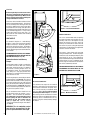
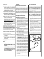
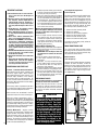
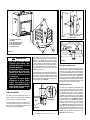
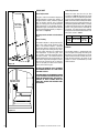
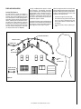
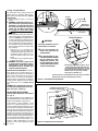
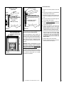
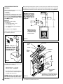
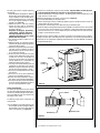
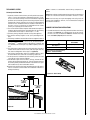
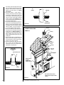
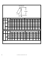
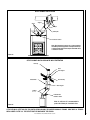
INSTALLATION AND
OPERATION INSTRUCTIONS
CAMBRIA™
Wood-Burning Fireplace
P/N 850,057M REV. E 06/2010
TM
MODEL
CAMBRIA
This installation manual will enable you to obtain a safe, efficient
and dependable installation of your fireplace system. Please read
and understand these instructions before beginning your installation
or operating the fireplace.
CAUTION: Do not alter or modify the fireplace or its components under
any circumstances. Any modification or alteration of the fireplace
system, including but not limited to the fireplace, chimney components
and accessories, may void the warranty, listings and approvals of
this system and could result in an unsafe and potentially dangerous
installation.
Lennox Hearth Products wood-burning fireplaces are designed for use
as a supplemental heater. They are not intended for continuous use
as a primary heat source.
SAVE THESE INSTRUCTIONS
FOR FUTURE REFERENCE
WARNINGS
WARNINGS
• Hot! Do not touch! The glass and
surfaces of this appliance will be hot
during operation and will retain heat
for a while after shutting off the appliance. Severe burns may result.
• Carefully supervise children in the
same room as appliance.
• If small children are present in the home, it is
recommended that this appliance be fitted with
a firescreen kit.
• The fireplace cannot be operated without a door
or firescreen. Consult your dealer to select the
correct replacement door or firescreen.
• Important! To assure proper alignment of glass
doors: Install this fireplace in a square and
plumb condition, using shims as necessary at
sides and/or bottom.
• Install the fireplace only as described in these
instructions.
Listed to standards:
ULC-S610 and UL-127
Report No. 3092554
PICAMBRIA-A REV. 5 JUNE 2010
IMPORTANT! GENERAL SAFETY
PRECAUTIONS. READ AND
UNDERSTAND THESE SAFETY
RULES BEFORE YOUR FIRST FIRE.
WARNING
The CAMBRIA™ fireplace must
be installed with an outside air
kit intake, which is included with
the fireplace
WARNING
THE FIREPLACE MUST BE OPERATED WITH THE DOORS FULLY
OPENED OR DOORS FULLY
CLOSED. IF THE DOORS ARE
LEFT PARTLY OPENED, GAS AND
FLAME MAY BE DRAWN OUT OF
THE FIREPLACE OPENING, CREATING RISKS OF BOTH FIRE AND
SMOKE. IF THE UNIT IS OPERATED WITH THE DOORS FULLY
OPENED, THE FIRE SCREEN
MUST BE USED.
CAUTION
NEVER use gasoline, gasolinetype lantern fuel, kerosene,
charcoal lighter fluid, naphtha,
engine oil or similar liquids to
start or “freshen up” a fire in this
fireplace. Keep any flammable
liquids a safe distance from the
fireplace at all times.
WARNING
THIS FIREPLACE HAS NOT BEEN
TESTED WITH AN UNVENTED
GAS OR A FIREPLACE INSERT.
TO REDUCE RISK OF FIRE OR
INJURY, DO NOT INSTALL AN
UNVENTED GAS LOG SET OR
FIREPLACE INSERT OR OTHER
PRODUCTS NOT SPECIFIED FOR
USE WITH THIS FIREPLACE.
WARNING
Never leave your fireplace unattended while it is burning.
2
CAUTION
Use care when selecting window
treatments for windows located
near the fireplace. Avoid using
combustible flowing window
treatments such as curtains
on nearby windows that are of
sufficient length to be blown in
front of an open flame when the
window is opened.
Keep any combustible furniture,
materials or decorative pillows
at least 48" (1219 mm) from the
front fireplace opening.
WARNING
Never leave children unattended
when there is a fire burning in
the fireplace.
IMPORTANT
When burning wood, use SOLID
NATURAL DRY WELL-SEASONED
WOOD ONLY. Hardwoods are
recommended (soft woods tend
to burn very quickly).
• DO NOT burn treated wood,
charcoal, coal, trash, cardboard, driftwood, woods dipped
in tar, Christmas tree greens,
pitch, pine tar, creosote, chemical chimney cleaners, flame
colorants, polystyrene packaging, wood products with synthetic
binders (i.e. plywood). Plywood,
lumber and other misc. materials can produce abnormally high
temperatures, sputtering and
smoking fires and may contain
hazardous chemicals to treat
insects and fungus.
• Burning unapproved fuels can
produce excessive temperatures
(overfiring), beyond the design
capabilities of the fireplace and
may produce excess sparks or
may contain hazardous chemicals. Burning unapproved fuels
can result in a chimney fire, a
house fire, personal injury, death
or loss of property.
WARNING
To avoid the risk of damaging
fireplace materials and increasing the risk of fire, do not use the
fireplace to cook or warm food.
WARNING
Be careful adding wood fuel to the
fire or handling fireplace tools such
as shovels, tongs or pokers.
WARNING
Never modify or alter your fireplace system in any way. To do
so may create a potential fire
hazard and void the limited warranty, listings and approvals of
this system.
WARNING
The bottom refractory can be
cracked by excessive abuse such
as tossing heavy logs onto the
grate or gouging with fireplace
tools. Exercise caution when
adding wood to your fireplace.
WARNING
Neither the manufacturer nor the
seller warrants “smoke free”
operation nor are we responsible
for inadequate system draft
caused by mechanical systems,
general construction conditions,
inadequate chimney heights,
adverse wind conditions and/or
unusual environmental factors or
conditions beyond our control.
WARNING
Always ensure that the air inlet to
the fireplace is free from debris
and any other obstructions that
can block the entrance of air.
WARNING
For spectacular fire view and
optimum efficiency of your fireplace, we recommend that the
wood be placed as far back as
possible in the fireplace.
Congratulations!
OPTIONAL EQUIPMENT
When you purchased your new fireplace, you joined the ranks of thousands of individuals
whose answer to their home heating needs reflects their concern for aesthetics, efficiency
and our environment. We extend our continued support to help you achieve the maximum
benefit and enjoyment available from your new fireplace.
Thank you for selecting a Lennox Hearth Products fireplace as the answer to your home
supplemental heating needs.
TABLE OF CONTENTS
Safety Rules.......................................Page 2
Introduction.......................................Page 3
Parts Required ..................................Page 3
Optional Equipment............................Page 3
Operating The Fireplace .....................Page 3
Fuel....................................................Page 3
Combustion Control . ........................Page 4
Refueling For Best Performance........Page 5
Smoking – Causes And
Troubleshooting...........................Page 5
Important Cautions............................Page 6
Maintaining Your Fireplace . ..............Page 6
Creosote.............................................Page 6
Chimney Maintenance........................Page 6
Dealing With A Chimney Fire..............Page 6
Disposing of Ashes............................Page 6
Door Finish Casing Care.....................Page 6
Refractory Replacement.....................Page 6
Door Installation................................Page 6
Door Adjustment................................Page 7
Glass Care..........................................Page 8
Gasket Replacement .........................Page 8
Andirons............................................Page 8
Fireplace Installation .........................Page 9
Locating The Fireplace .......................Page 9
Framing, Facing And Mantel...............Page 10
Hearth Extension Requirements . ......Page 10
Cold Climate Installations...................Page 10
Framing Dimensions..........................Page 11
Insulated Chase Construction............Page 12
Nailing Flanges...................................Page 12
Mantel and Facing..............................Page 12
Optional Fireplace Blower...................Page 13
Hot Air Ducting Installation ...............Page 14
Gravity Kit..........................................Page 14
Outside Air Kit . .................................Page 16
Chimney System................................Page 17
Offset Chimney Installation................Page 20
Angled Wall Radiation Shield.............Page 22
Chimney Support Installation.............Page 22
Chimney Chase And
Multiple Terminations......................Page 22
Installation Accessories.....................Page 23
Chimney Components Lists...............Page 23
Replacement Parts.............................Page 25
Specifications.....................................Page 25
Clearances.........................................Page 25
Product Reference Information..........Page 26
THE FIREPLACE
INTRODUCTION
The Cambria™ wood-burning fireplace is a
mid-efficient, heat radiating fireplace. You will
receive a lifetime of comfort and enjoyment
from your fireplace provided it is installed,
maintained and operated properly.
• Please read these instructions and retain
this manual for future reference.
• Before beginning the fireplace installation,
consult the local authorities to obtain your
building permit and check your local building
codes. Install the fireplace only as described
in these instructions and using only Lennox
Hearth Products components.
• These appliances are not approved for
Manufactured Home installations.
• When planning a fireplace installation the
following information must be determined
before beginning.
1.Where the fireplace is to be installed.
2.The configuration of the chimney.
3.Optional components installation (fan,
hot air ducting, etc).
4.Electrical wiring.
5.Framing and finish details.
Parts Required
• Fireplace model: Cambria
• 10” diameter chimney - Model Secure Temp
or Nova Temp HT6103+ insulated stainless
steel chimney or 10” (AC) air-cooled manufactured by Security Chimneys International
only, including:
- Chimney lengths
- Elbows (where necessary)
- Associated components as per these
installation instructions
• Outside air kit (included)
ASHT+,
• 5” flexible venting system (central forced
air kit) (see section 3.5.2)
• UZY5 blower. The blower installation re-
quires that an electrical connection of a 120v
electrical box located outside the fireplace
be made prior to moving the fireplace in its
final position. (see Optional Fireplace Blower
on Page 13)
• Gravity venting system (see Central Forced
Air Kit on Page 15)
OPERATING THE FIREPLACE
Fuel
USE SOLID NATURAL WOOD FUEL ONLY. The
Cambria fireplace is designed to work best when
fueled with seasoned cordwood. Hardwoods are
preferred to softwoods since the energy content
of wood is relative to its density. Hardwoods will
result in a longer burning fire and less frequent
refuelling. A moisture content of 15% to 20%
(seasoned) is recommended. Wood that has
been cut and split and let to dry under a cover for
a period of one year will usually meet that criteria.
The required drying time will vary depending on
the climate. Wood that is packed tight together
will take longer to dry. Seasoned wood is darker
in color than wet wood and will have visible cracks
in the grain on the ends. Excessively wet wood
will be difficult to burn and will result in lower efficiency, increased creosoting and deposits on the
glass and in the chimney. Excessively dry wood
will burn well but will also have higher emissions
and shorter burning time.
Do not burn scrap or garbage, treated wood or
wood such as driftwood from the ocean which
has been exposed to salt or other chemicals.
Salt or chemicals can corrode the firebox and
chimney. Do not burn large amounts of paper,
cardboard, Christmas tree branches or building
construction materials. Intense firing with these
materials may overheat the fireplace, causing
damage to the unit, a fire or even possibly igniting a chimney fire if the chimney is creosoted.
Burning unapproved fuel, resulting in excessive
pollutants being emitted, may be prohibited and
subject to a fine or other penalty by the authority
having jurisdiction in your area.
Processed firelogs can be used. Use only firelogs that have been evaluated for the application
of fireplace and refer to firelog warnings and
caution markings on packaging prior to use.
3
First Fires
Before using the fireplace make sure to remove
the plastic wrapping on the door. Remove all
remaining glue with mild soap. Make sure the
doors are properly adjusted, thus avoiding color
change to finish due to overheat.
The first 5 or 6 fires should be small fires of short
duration (about 30 to 60 minutes). This will help
cure the refractory bricks. During the first few
fires of this appliance there may be some odor
and smoke due to the curing of the paint, dust
accumulation and burning off of lubricants used
in the manufacturing process. It may set off a
smoke alarm located in the same room. For
this reason the room should be well ventilated
for the first few fires.
Open
Chimney
Damper
(A)
Open
Back
This is the recommended mode of operating
the Cambria fireplace and should be the one
normally used since it will deposit the least
amount of creosote on the glass and in the
chimney. The combustion air control must be
3/4 closed .The precise setting will depend on
many factors, including chimney length and the
moisture content of the wood.
Closed
Front
The Cambria™ fireplace is a mid-efficiency
fireplace. In spite of the heat that the Cambria
fireplace can deliver, it should not replace the
main source of heat in your home. This fireplace
will bring extra warmth and ambiance to your
home by distributing its heat as described further
in the manual.
FOR MAXIMUM HEAT OUTPUT, WE STRONGLY
RECOMMEND THE INSTALLATION OF HOT AIR
DUCTING SYSTEM (See Page 14).
n Air
Combustio(B)
Control
Combustion Control and Chimney
Damper
The chimney damper is controlled by the handle
inside the firebox (see Figure 1-A). It is in closed
position when the handle is visible (front) and
in the open position when not visible (pushed
back). The combustion air damper is controlled
by the lower handle (see Figure 1-B). The control
can be moved from open position at left all the
way to the close position at right.
This air combustion control should be in the
closed position when the fireplace is not in
operation. This will minimize air infiltration.
The combustion air control should be opened
before opening the doors to minimize the
possibility of back draft coming into the
room (see Figure 1-A). Also see Smoking
- Causes and Troubleshooting for more details
(on Page 5).
Open
Closed
For instance, a long chimney will necessitate
closing the damper more. To obtain the proper
combustion, close the damper completely, then
open it about 1/4” to 1/2”. Three medium size
pieces of cordwood burning on a bed of hot coals
will burn about 1-2 hours. Softwoods may be
burned using this method but the combustion
time will be substantially reduced.
FOR MAXIMUM HEAT OUTPUT, WE STRONGLY
RECOMMEND THE INSTALLATION OF THE
OPTIONAL HOT AIR DUCTING SYSTEM.
Figure 1
Accelerated Combustion
The maximum heat output for the Cambria
fireplace is achieved by burning with the door
closed and the combustion air opened. However, it will be necessary to reload with wood
every hour. This is the least efficient method
of burning the Cambria fireplace. Use caution
when burning with the combustion air control
wide open. Only burn cordwood in this manner.
Small dry pieces of softwood will burn very
intensely using this method and may damage
the firebox.
WARNING: The air combustion control
must be in the open position if the fireplace is operated with the doors open.
4
Figure 2 - Accelerated Combustion
Medium Combustion
Heat Output
The Cambria fireplace includes a combustion
air control that sets the flow of air entering
the firebox and control the fire. The fireplace
also includes a chimney damper that is not
a combustion control. The chimney damper
must always be in fully open position when
the fireplace is used and should be closed only
when all ashes are cold.
Closed
NOTE: DIAGRAMS & ILLUSTRATIONS ARE NOT TO SCALE.
Open
Figure 3 - Medium Combustion
Closed
Building a Fire
A)To start a fire, place several crumpled up
balls of newspaper in the firebox. Place small
dry pieces of kindling on top of the paper,
criss-crossing the kindling so that there are
air spaces in between. The kindling should
be placed at the center of the firebox so as
to allow for sufficient air circulation.
B)Open the dampers and light the newspaper.
Leave the doors partially opened (1 to 2
inches) to facilitate the start-up.
C)Once kindling fire is well established, cordwood can be added. Close the doors and
leave the combustion air control open in
accelerated combustion position.
D)When the fire burns well set the primary
control to the desired burn level.
The unit will burn best with 2-3 pieces of
cordwood spaced 1 to 2 inches apart and
allowing air to get under the fuel. Crisscrossing or arranging the fuel so that air
can get underneath will help the fire to get
started easily. The unit should be operated
with the air control fully open long enough
to get the cordwood well ignited.
WARNING: The Cambria™ fireplace was designed to allow a spectacular view of the fire.
The Cambria fireplace should never be filled
in excess (five big logs or more). Excessive
fire could damage the fireplace’s hearth and
refractory brick and void the warranty.
REFUELING FOR BEST PERFORMANCE
To reload the Cambria fireplace:
A)Completely open the combustion air control
(see Figure 2).
B)Open the doors about 1” and wait 5 seconds
until the airflow has stabilized. Then open
the doors completely, put the logs in and
close the doors.
C)Set the combustion air control to the desired
burn level.
Notes:
• For spectacular fire and optimization of the fireplace efficiency, we recommend
that the wood load be placed as far back
as possible.
• It may be necessary to turn off any blower(s)
in operation during the refueling process in
order to minimise smoking in the room. It
is recommended to wait 15 to 30 minutes
before turning the blower(s) back on to
ensure successful rekindling.
SMOKING –
CAUSES AND TROUBLESHOOTING
To reduce the likelihood of smoke coming
into the room when opening the door, set the
combustion air controls to the left (“Accelerated Combustion”) before opening the door.
Your fireplace has been designed and tested
to provide smoke free operation. Occasionally,
there may be a small amount of smoking upon
lighting the fire until the chimney heats up. If
the fireplace continues to smoke it is probably
for one of the following reasons:
A.The doors are partially opened
When you open the doors, open them completely.
B.Negative pressure in the house
A fire needs air to burn. This air must be
replaced through the outside air duct (see
Outside Air on Page 16). When operating
the Cambria fireplace, open a nearby window
temporarily to check if there is adequate
replacement air supply.
C.Fans operating (e.g.: range hood)
Fans such as range hoods or bath fans draw
air out of the house and may actually cause a
negative pressure in the house. Turn off all
fans and open a nearby window to determine
if this is the cause of the problem.
D.Wet wood
Wet or tarred wood will smoulder and smoke
instead of burning properly. Your dealer can
help you determine if you have properly
seasoned wood for burning.
E.Dirty or blocked chimney
Check to make sure the chimney is clear and
clean. If dirty call a certified chimney sweep
or use a properly sized chimney brush to
clean.
F. Chimney not long enough
The minimum chimney height is 15 feet (4.6
m) not including the fireplace height. The
chimney must extend at least 3 feet (915
mm) above its point of contact with the roof
and at least 2 feet (610 mm) higher than any
roof or wall within 10 feet (3 m) of it. When
installed with offsets, the minimum chimney
height is 18 feet (5.5 m). Additional height
will increase draft and will decrease the
tendency to smoke.
G.Poor chimney draft
With no fire, there should be sufficient draft
to exhaust cigarette smoke introduced under
the baffle. Chimneys installed against an
outside wall without protection may generate back draft problems which will cause
start-up problems. To prevent this, open
a nearby window; roll up a piece of paper,
light it and hold it in the upper part of the
firebox to warm up the chimney. Wait until
the draft is sufficient, then start the fire.
H.Blower for central forced air kit
Make sure that the blower is at the “off”
position when you open the fireplace door
for reloading.
NOTE: DIAGRAMS & ILLUSTRATIONS ARE NOT TO SCALE.
GAS LOG INSTALLATION
This fireplace is designed to allow the installation
of a gas burner. In such a case, the installation
must conform with the National Gas Code ANSI
Z223.1 and Z21.60. Warning: When using a
gas burner, it is mandatory to keep the chimney
outside air register opened.
This fireplace has provision for the installation
of a gas pipe and is intended only for connection
to a decorative gas appliance incorporating an
automatic shutoff device and complying with
ANSI Z21.60-M96/CGA 2.26-M96, Standard
for Decorative Gas Appliances for Installation
in Solid-Fuel Burning Fireplaces (reference
Clause 4.1.3 T).
1. Remove the 1 inch knock-out on the right
side of the fireplace and on the right side
refractory.
2. Drill a one inch hole in the hearth right side
coaxial to the refractory opening.
3. Assemble a rigid 3/8” N.P.T. iron pipe with
two 90º elbows. Make sure to have 5-11/16”
clearance between the two pipes (see Figure
4).
4. Through the hearth bottom or back openings
insert the mounted pipe through the side
of the firebox and the firebrick. Make sure
the top elbow is as close as possible to the
hearth to keep a minimum clearance to the
retractable door.
5. Insert a pipe through the 1 inch exterior
knock-out and fix it to the 90º elbow already
in place.
Note: In some regions, the use of a flexible gas
pipe is allowed. Consult your local authority.
5-11/16”
(145mm)
Figure 4
5
IMPORTANT CAUTIONS
A.Do not block the hot air vents to the fireplace as this will cause the fireplace to
overheat.
B.Never use gasoline, gasoline-type lantern
fuel, kerosene, charcoal lighter fluid, or
similar liquids to start or ‘freshen up’ a
fire in this fireplace. Keep all such liquids
well away from the fireplace while it is in
use.
C.Do not burn coal. The sulphur in coal will
corrode the firebox and chimney.
D.Keep combustible materials at least 48”
(1.2 m) away from the front of the fireplace
opening.
E.Never leave children unattended when
there is a fire burning in the fireplace.
F. Do not use the CAMBRIA as an incinerator
to burn paper, cardboard or construction
material such as pressed wood, plywood
or lumber. Use only untreated wood. Wood
protectors, metallic paper, coal, plastic,
waste, sulphur and/or oil will damage the
fireplace.
G.Do not burn driftwood which has been in the
ocean or salt water. The salt will corrode
the firebox and chimney.
H.Do not burn wood in the area in front of the
grate.
I. Do not allow the wood to smoulder or burn
without flame, since this will produce
excessive creosote in the unit as well as
increased particulate emissions.
MAINTAINING YOUR FIREPLACE
Creosote - Formation and Need for Removal
When wood is burned slowly, it produces tar
and other organic vapors, which combine
with expelled moisture to form creosote. The
creosote vapors condense in the relatively
cool chimney flue of a slow-burning fire. As
a result, creosote residue accumulates on the
flue lining. When ignited this creosote makes
an extremely hot fire.
The chimney shall be inspected at least twice
a year during the heating season to determine
when a creosote buildup has occurred.
When creosote has accumulated it shall be
removed to reduce the risk of a chimney fire.
When the creosote accumulation is large, a
creosote fire in the chimney can damage the
chimney and overheat the surrounding wood
framing. Creosote formation in a chimney can
be minimized by making sure there is always
visible flame burning, avoid smouldering fires
and by proper refuelling techniques.
6
Chimney Maintenance - Regular chimney
inspection and maintenance combined with
proper operation will prevent chimney fires.
Keep your chimney clean. Do not allow more
than 1/16” (1.6 mm) creosote build up in your
chimney. The amount of creosote will depend
on variables such as frequency of use and type
of fire. We recommend that you:
A.Initially inspect the chimney system weekly.
From this, you will learn how often it will be
necessary to clean your chimney.
B.Have your chimney cleaned by a qualified
chimney sweep. If you wish to clean it yourself, we recommend using a stiff plastic or
non-metallic brush. If a metal brush is used,
its size should be slightly smaller than the
flue to avoid damaging the chimney. Do not
use a brush that will scratch the stainless
steel interior of the chimney.
Warning: The chimney damper must be opened
when sweeping the chimney to avoid ash and
creosote accumulation in the fireplaces air
circulation area.
C.Do not expect chemical cleaners to keep
your chimney clean. The rain cap can be
removed for inspection and/or cleaning of
the chimney. Using gloves, firmly grip the
upper portion of the rain cap. Turn the cap
and lift it off the chimney.
Dealing With a Chimney Fire
Regular chimney maintenance and inspection
can prevent chimney fires. If you have a chimney
fire, follow these steps:
1. IMPORTANT: Close the fireplace door and
the combustion air controls; this will stifle
the fire.
2. Alert your family of the possible danger.
3. If you require assistance, alert your fire
department.
4. If possible, use a dry chemical fire extinguisher, baking soda or sand to control the
fire. Do not use water as it may cause a
dangerous steam explosion.
5. Ensure that sparks and hot embers coming
out of the chimney are not igniting the roof.
6. Do not use the fireplace again until your
chimney and fireplace have been inspected
by a qualified chimney sweep, your dealer,
or a fire department inspector.
Refractory Brick Replacement
(refer to Figure 6)
The intense heat of the fire will normally cause
hairline cracks in the refractory brick. These
cracks can be minimized by proper curing as
described in First Fires on Page 4. They will
not normally diminish the effectiveness of the
refractory brick. If large cracks develop, then
the refractory should be replaced. To replace
the refractory bricks, follow these steps:
1..
2..
3..
4..
5..
6..
Remove the front refractory bricks
Remove the andirons
Remove the side refractory supports
Remove the side refractory bricks
Remove the back refractory brick
Remove the bottom refractory brick
To install the new refractory bricks, follow the
above steps in reverse.
DOOR FRAME FINISH CARE
Use a glass cleaner and a soft cloth to polish
the casing. Do not use abrasives such as steel
wool, steel pads or an abrasive polish for they
may scratch the frame’s finish.
Door Installation
(refer to Figure 5)
The doors on the Cambria fireplace are factory
installed. To remove the doors, remove the
finishing trim, then simply pull them up from
the hinges. The door adjustment has been set
at the factory. If the fit is still not perfect, you
can adjust the door using the hinge screws.
(See Figure 8, #1)
DISPOSING OF ASHES
Note: For better performances, we recommend
leaving 1/2 inch of ashes in the firebox.
Remove ashes only when the fire is out and
the ashes are cold (24 to 48 hours after the
fire is out). Do not leave the ashes in the house
as they give off carbon monoxide and other
toxic gases.
WARNING
Disposal of Ashes: Ashes should
be placed in a metal container
with a tight fitting lid. The closed
container of ashes should be
placed on a non-combustible floor
or on the ground well away from
all combustible materials, pending final disposal. If the ashes
are disposed of by burial in soil
or otherwise locally dispersed,
they should be retained in the
closed container until all cinders
have thoroughly cooled.
Figure 5
NOTE: DIAGRAMS & ILLUSTRATIONS ARE NOT TO SCALE.
Figure 8
1. Front Refractory Brick
2. Andirons
3. Side Refractory Supports
4. Side Refractory Bricks
5. Back Refractory Brick
6. Bottom Refractory
1. Adjustment Screw (adjusts
tightness of door seal)
2. Slider Stoppers
Door Lock
Adjustment
Screws
Tighten
Figure 6
WARNINGS
• Use only a Lennox Hearth
Products glass doors, specifically designed for the
Cambria fireplace.
• The fireplace cannot be operated without door or firescreen.
Consult your dealer to select
the correct replacement door
or firescreen.
• Important! To assure proper
alignment of glass doors:
Install this fireplace in a
square and plumb condition,
using shims as necessary at
sides and/or bottom.
The gaskets’ air-tightness can be adjusted using the adjustment screw located on the slider
stoppers (see Figure 8). Turning the screws
clockwise will shorten the travel of the slider and
increase the pressure on the door side gaskets.
This may lead to the doors being harder to lock,
so a good adjustment must be found between
a good gasket seal and easy door lock (see
Figure 8, balloon #1).
The door lock can also be adjusted. Remove the
front refractory brick and loosen the two screws
in the middle front of the firebox bottom. Push
or pull on the handle of the door lock. Pushing
the handle will tighten the door seal in the center
of the fireplace (see Figure 9).
To readjust the door side to side position, unscrew the fireplace hinges or the door hinges.
Move the doors side to side until the top of the
two doors are aligned (Figure 7).
Loosen
Door Opening Adjustment
The doors opening angle can be adjusted. This
allows the doors to slide in the fireplace without
interference or friction with the finishing facing, which could damage the paint. The screws
located under the bottom hinges (Figure 11)
are used as door opening stops. Tightening or
loosening these screws will keep the door handle
from hitting the finishing facing and won’t allow
friction between door gasket and hearth when
the door is fully pushed in the fireplace.
Bearing Maintenance
DOOR ADJUSTMENT
The doors are factory adjusted for proper air
tightness and fit. They may need to be readjusted
if the alignment has shifted in freight.
Figure 9
Door
Door Hinges
Figure 7
NOTE: DIAGRAMS & ILLUSTRATIONS ARE NOT TO SCALE.
The doors are assembled on retractable sliders using roller bearings for easy movement.
Cambria fireplace has been designed to ensure
that bearing maintenance is easy. Remove
the decorative facing by unscrewing the four
decorative caps and the four screws holding
the facing. Remove the doors by lifting them up
from the female hinges (see Figure 5). Remove
the slider stoppers (see Figure 8) and take the
slider bearing assembly out of the fireplace.
Unscrew the nuts to change the bearings
(see Figure 10). Original bearing contains no
grease to resist heat. Adding grease or changing bearings with greased bearing may cause
a malfunction of the slider. Please use Lennox
Hearth Products replacement parts only (see
Page 25 for part numbers).
7
Unscrew the
nuts to change
the bearings
GLASS CARE
Gasket Replacement
Glass Replacement
Remove the doors from the unit (see Door
Installation on Page 6) and lay them on a clean
nonabrasive surface. To replace the gasket, first
remove all of the old gasket and gasket cement.
Make sure that the surface is totally clean before
applying new cement (a high temperature silicone caulking rated at 500°F / 260°C, is suitable)
or adhesion problems may result. Apply gasket
cement to the gasket channel and install the
new gasket. This replacement part is available
from your Lennox Hearth Products dealer in the
dimensions shown in Table 1.
The glass used for the Cambria™ fireplace is
a high temperature ceramic glass (1400°F). If
the glass breaks or cracks, it must be replaced
with an identical ceramic glass. Tempered
glass or ordinary glass will not withstand the
high temperatures of the Cambria fireplace.
Replacement glass should be purchased from
a Lennox Hearth Products dealer (see “Replacement Parts” on Page 25).
Do not operate the unit with cracked or broken
glass.
Figure 10
Gasket
Part #
Dimensions
Qty
Glass Cleaning
Around
the door
PR-SR1823N
58-3/4”
5/8” dia.
2
The Cambria fireplace is designed to keep the
glass clean under normal operating conditions. If the Cambria fireplace is operated
continuously with the combustion air controls
closed, the glass will tend to get dirty unless
the fuel, firebox and glass are maintained at
hot temperatures. To clean the glass, there
are a number of specially designed cleaners
to remove creosote. Your authorized Lennox
Hearth Products dealer can recommend a suitable cleaner. Regular household glass cleaners
will not clean creosote. Do not use abrasives
such as steel pads, steel wool or oven cleaner
as they will scratch the glass.
Table 1
DO NOT USE CHEMICAL GLASS CLEANERS
ON PAINTED SURFACES AS IT MAY CAUSE
THE PAINT TO PEEL.
Door Angle (hang)
Adjustment Screw
CAUTION : DO NOT ALLOW WINDOW CLEANER
TO GET IN CONTACT WITH DOOR GASKET OR
PAINT ON FACADE OR DOOR. ONCE CLOSED,
CONTACT OF GLASS CLEANER WITH THE
FIREPLACE FACADE CAN PROVOKE PAINT
PEELING OFF.
Figure 11
8
NOTE: DIAGRAMS & ILLUSTRATIONS ARE NOT TO SCALE.
Andirons
The Cambria fireplace is equipped with andirons designed to keep logs from falling into
the door. It must be replaced only by Lennox
Hearth Products andirons available from your
dealer. No other andirons, log retainer or log
support is sold or recommended by Lennox
Hearth Products.
FIREPLACE INSTALLATION
Locating The Fireplace
The best location to install your fireplace is
determined by considering the location of
windows, doors, and the traffic flow in the room
where the fireplace is located, allowing space in
front of the unit for the hearth extension and the
mantel, and taking into consideration the location of the hot air ducts (optional), outside air
kit and chimney. If possible, you should choose
a location where the chimney will pass through
the house without cutting floor or roof joists
(see fireplace dimensions on Page 11).
Usually, no additional floor support is needed
for the fireplace. The adequacy of the floor
can be checked by first estimating the weight
of the fireplace system. Weights are given on
Page 25. Next, measure the area occupied by
the fireplace. Note the floor construction and
consult your local building code to determine
if additional support is needed.
The Cambria™ fireplace may be installed directly
on the floor or on a raised base but a minimum of
7 feet 6 inches (2.3 m) measured from the base
of the appliance to the ceiling is required.
When selecting the location, the chimney outlet
position and the direction of the wind are important factor affecting the chimney performance.
To allow a maximum draft and to reduce wind
turbulence, the chimney must:
• Penetrate the highest part of the roof.
• Be installed as far as possible of roof offsets,
trees or any other obstructions that may
cause wind turbulence and back drafts in
the chimney.
• The least amount of offsets (elbows) possible.
Location Recommended
Marginal Location
Wind Direction
Location
Not
Recommended
Location
Not
Recommended
Outside Air Intake
Facing the Wind
Figure 12
NOTE: DIAGRAMS & ILLUSTRATIONS ARE NOT TO SCALE.
9
Framing, Facing And Mantel
The construction of the framing, facing, and
mantel must be in accordance with the standards and the following illustrations (Figures
15 through 20):
A.Frame the fireplace using 2” x 3” or heavier
lumber.
Fireplace
D.WARNING: The fireplace must not be
in contact with any insulation or loose
filling material. Cover the insulation
with drywall panels or any other rigid
material around the fireplace.
Fireplace
Free Space u
Tile or Marble
B.WARNING: Combustible materials cannot be used in the space directly above
the fireplace, except for the studs above
the facade that support the facing and
mantel. This area must remain empty
for a height of 7 feet 6 inches (2286
mm) measured from the base of the
appliance.
C.Frame the fireplace with vertical studs at the
sides of the fireplace running from floor to
ceiling (see Figure 15). If combustible facing
is to be used, position the studs back, from
the front edge of the fireplace the thickness
of the facing material so that the facing can
be installed flush with the fireplace facing.
Frame headers between the vertical studs
only as follows:
• Place 2” x 3” or 2” x 4” headers, only
along the upper part of the front, side
and back faces. Do not put wood or any
combustible material within the area
above the fireplace except on the front
facing.
• Place headers only as required to support
the facing and mantel.
Tile or
Marble
Cement
Board
Minimum 1/2”
Cement Board
v
Elevated Fireplaces
WARNINGS:
Fireplace
THE HEARTH EXTENSION IS TO BE INSTALLED ONLY AS ILLUSTRATED.
u.D O
NOT PACK REQUIRED AIR
SPACES WITH INSULATION OR
OTHER MATERIALS.
Platform
vTHE
CRACK BETWEEN THE FIREPLACE AND THE HEARTH EXTENSION
MUST BE SEALED WITH A NONCOMBUSTIBLE MATERIAL SUCH
AS A NON-COMBUSTIBLE SEALING
STRIP OR SAND CEMENT GROUT IN
THE AREA SPECIFIED ABOVE.
2”
Elevated fireplace installations require a special
“Z” Metal Safety Strips (field provided), in place
of the safety metal strip shown above. The safety
strip should extend the full width of the fireplace.
When more than one safety strip is used they
must overlap by a minimum of 1”.
Hearth Extension Requirements - The Cam-
bria™ fireplace may be installed directly on a
combustible floor; however, the combustible
floor in front of the fireplace must be covered
with a 1/2 inch (13 mm) of non-combustible
support material (cement board, cement block
or other) before applying the finish material
(tile, marble, stone, etc.) (see Figures 13 and
14).
WARNING: It is important not to cover the
air ventilation opening below the facade
trim. (free space - Figure 13).
Hearth extension of an elevated fireplace must respect the same minimal
dimensions than a fireplace installed directly on the floor.
Figure 13 - Hearth Extension Requirements
Combustible material allowed in
the airspace above this area.
Cold climate INSTALLATIONS
Mantel
Climates where temperatures will fall below
32° F (0° C).
12”
MAX
The heating performance of the appliance will
vary depending upon the level of insulation, house
design, how the appliance is operated, etc.
10
If this fireplace is being installed in a cold
climate, it is especially important to seal all
cracks around the fireplace and wherever cold
air could enter the room with noncombustible
material. Also, the outside air inlet duct should
be wrapped with noncombustible insulation to
minimize the formation of condensation. Do
not place insulation materials directly against
the chimney sections. We recommend that you
use the insulated wall radiation shield since it
will maintain the home’s thermal barrier. AC
chimney is NOT recommended in very cold
climates (in areas with temperatures below
0°F (-18°C).
2 x 4 Framing
v
59” Min.
24”
45°
18”
Hearth
Extension
Non-Combustible
Material
Figure 14 - Hearth Extension and Clearances
4”
33-3/4”
Framing Dimensions - Model Cambria™
2” x 3”
Min.
Do not fill the
space above the
fireplace with
any material
CORNER
INSTALLATION
32-7/8”
D
(835mm)
J
F
27-7/8”
E
7’ 6”
(2.3m)
Min.
B
PARALLEL / CHASE INSTALLATION
Back Wall of Chase/Enclosure
Including Finising Materials if any
OUTSIDE CHASE
C
G
* Zero Clearance
From Back
Spacer to Wall
A
G
Plywood 1/2”
A
Rough Framing Face (Unfinished Shown)
Rough Framing Face
(unfinished shown)
46-1/2”
FRAMING DIMENSIONS
Fireplace Opening Width
A
48-3/4’’
1238 mm
B
59-3/8’’
1508 mm
C
48-1/2’’
1232 mm
D
23-1/4’’
591 mm
E
102-1/4”
2597 mm
F
51-1/8”
1299 mm
G
28-7/8’’
733 mm
J
72-5/16’’
1837 mm
1”
24”
17-7/8”
12-3/8”
27-7/8”
1-3/8”
Notes
Due to Lennox Hearth Products ongoing commitment
to quality, all specifications, ratings and dimensions
are subject to change without notice.
All framing dimensions calculated for 1/2" dry wall at
the fireplace face. If sheathing the chase or finishing with other thickness materials, calculations will need to be made.
57-1/8”
(1451mm)
35-7/8”*
(911mm)
28-1/4”
(718mm)
The fireplace must not be in contact with any insulation
or loose filling material. Cover the insulation with
Drywall panels around the fireplace.
2-5/8”*
(67mm)
59-1/8”
(1502mm)
27-7/8”
(708mm)
36-1/4”*
(921mm)
* Dimensions to tiling
flange behind the trim.
46-1/2”
(1181mm)
Figure 15 - Framing Dimensions
NOTE: DIAGRAMS & ILLUSTRATIONS ARE NOT TO SCALE.
11
Insulate Joists
Same As Ceiling
Insulated Chase Construction
Storm Collar
Roof Support
Flashing
Attic Radiation
Shield
Floor
Ceiling
Wall
NOTE:Itisrecommendedthatthechasewalls
and floor be insulated in the same manner,
using the same insulation, as the rest of the
building, below the attic.
FIREPLACE
SEE NOTE
8’8'
(2.4
m)
Level
Level
Unbend to floor
and nail/screw
Nailing Flange
(2 places each side)
1. Combustible material must be installed flush
with the fireplace. It may not project in front
of and on the fireplace (i.e. the steel facade
of the fireplace) (see Figure 19).
2. Non-combustible materials such as brick,
stone or ceramic tile may project in front
of and onto the fireplace facing (see Figure
20).
MANTEL AND FACING
The mantel must be installed at least 59”
(1500 mm) above the base of the fireplace
(see Figure 18).
Fireplace Frame Section
(Top View)
IMPORTANT
The facade must be removable
once installed. The facade is
designed to overlap any facing
material installed on the front of
the fireplace. If thicker material
is installed, use the facade as a
template and make sure it can be
easily removed for servicing.
3
1
4
5
2
6
1
2
3
4
7
1. Fireplace
2. Front of fireplace
3. Wood frame (2” x 3” min)
4. Drywall
5. Tiles
6. Rock board or other
7. Brick
Figure 17
NOTE: DIAGRAMS & ILLUSTRATIONS ARE NOT TO SCALE.
Outside
Base
Insulation
(Thermal Barrier)
Facing
Fireplace
Side
Solid
Continuous
Surface
Drywall or Any Rigid
Material
2” x 4”
1/2” Plywood
Four nailing flanges are provided to secure the
fireplace to the floor (see figure below). Bend
the nailing flanges down so that each flange is
flush with the floor, then using nails or screws,
secure the fireplace to the floor (2 places each
side). The heads of the screws or nails must
be large enough to completely cover the holes
in the nailing flanges.
12
CTDT
Termination
Opening
7’ 6”
(2.3 m)
7’ 10” Min.
(2.4 m)
Min.
Nailing Flanges
Firestop
• Must have the same firestopping
Nonresistance asNote:
adjacent
wall.
Combustible
Chase
• Must have the same insulation as
Flashing
adjacent ceiling.
Must Be
To regarding framing
• Follow localUsed
rules
Cover
construction.Chase
Firestop
Figure 16
Draft Stops
To install the blower,
Mantel and Facing
(Side View)
Flameproof Facing
Drywall
2” X 3” Min.
Spacer
Drywall
Mantel
2” x 3” Min.
}
Spacer
59”
Non-Combustible Panel Only
Non-Combustible
u
u
Panel Only
Metal Mesh Screwed in
Board and Fireplace
vFlameproof Facing
v
Figure 20
Figure 18
Only non-combustible material should be superposed or
projecting over the front of the
fireplace.
59”
Min.
Figure 19
Optional Fireplace Blower (UZY5)
A heat activated blower is sold as an option. It is
designed to be located in the back of the fireplace
and increase the air flow around the firebox. It
uses regular 120V and must be connected to the
main electrical circuit by a qualified electrician.
An electrical box must be installed outside the
fireplace.
1-Remove the refractory bricks and the andiron.
2-Remove the metal plates covering the bottom
and back of the hearth firebox.
3-Disconnect the main electric cable from the
blowers by unplugging its two quick connectors.
4-Remove the knock-out in the front right side
of the fireplace outer casing.
5-Install a metallic wire protector and slide the
blower main electrical cable from the outside
to the inside of the unit.
6-Install the two blowers in the back of the
fireplace through the holes in the back.
Warning: Make sure there are no contact
between the blowers and the door slider.
7-Reconnect the main cable quick connectors
and stick (magnet) the heat activate switch
under the right side of the firebox. Using
aluminum tape, make sure no wiring touch
the firebox by taping it to the bottom of the
fireplace panel.
8-Install all plates, bricks and andiron.
9-Connect the blower plug into the electrical
box located outside the fireplace.
WARNING: Because of the fireplace size and
obstructive air venting, we don’t recommend
the installation of the blower unless the gravity
ducting is installed on the fireplace.
If you wish to adjust the blower speed, an optional
variable speed control (VRUW) can be installed
in line with the wiring. Again, use a qualified
electrician for installation.
NOTE: DIAGRAMS & ILLUSTRATIONS ARE NOT TO SCALE.
13
HOT AIR DUCTING INSTALLATION
(OPTIONAL)
Different hot air ducting systems can be installed
with the Cambria™ fireplace:
• Gravity kit
• Forced air kit
The gravity kit is used when the rooms are on
same level or floor as the fireplace or on an upper level or floor. If the heat to be distributed
is on a lower level or floor, then the forced
air kit MUST be used.
When installing the double outlet system, the hot air outlets can be installed in the same room as
the fireplace, or one or both of the outlets can be installed in adjacent or upper rooms. Installing the
ducts at different elevations will tend to exhaust more heat out of the higher outlet (Figure 22).
Outlet Grill
WARNING: The outlet grills
should not be installed
facing upward through a
floor. Danger of burns can
result if grills in floor are
stepped on.
Gravity Kit
10’ Max.
13” x 13”
Double hot air outlet including:
(See Figure 21)
• 2 ea. telescopic lengths, 8” I.D.
• 2 ea. 90º elbows, 8” I.D.
• 2 ea. hot air outlet kits (grill and frames)
• 2 ea. adaptors
10’ Max.
See components list on Page 23.
Maintain at least 6-1/2”
(160 mm) clearance from
the outlet grill framing to
a combustible ceiling,
side wall or mantel.
Only the blower available with the fireplace can
be used with the gravity kit.
Frame
Grill
Figure 22
Rain Cap
Flashing
Collar
WARNING: Both pipes of
the double hot air outlet
must be installed. Any other installation may cause
fire and void warranty.
Flashing
Roof Support
Attic
Radiation
Shield
Firestop
68” Min.
(1727 mm)
Figure 21
u
The safety rules for hot air ducting gravity kit
installations are the following:
Minimum height* 68” (1727 mm)
Maximum length - See Figure 22
Non-Combustible
Flameproof
Facing
* The height of the louver must be measured
from the base of the Cambria fireplace to
the middle point of the louver.
14
WARNING: Both pipe of the double hot air
outlet must be installed. Any other installation can cause greater risk of fire and void
the warranty.
59” Min.
(1499mm)
Combustibles are not allowed below top spacers
u
Figure 23
NOTE: DIAGRAMS & ILLUSTRATIONS ARE NOT TO SCALE.
above the fireplace. Facing in front of fireplace
must be non-combustible below this area.
The duct system must be installed respecting
the following:
1. Remove the plates closing up the 8” (203mm)
diameter holes on top of the fireplace. Then,
cut the insulation in order to obtain two 8”
(203mm) diameter openings. Fix the adaptors on the fireplace openings by turning
clockwise (see Figure 21).
2. Maintain at least a 2” (50 mm) clearance
between the ducts and any combustible
material; the required hole size is 13” x 13”
(330 mm x 330 mm).
Exception: For the grills, the framing
can be 10-3/4” x 10-3/4” (275 mm x
275 mm) to provide the clearance as
required by the integral spacers on the
double outlet duct system.
3. The maximum number of elbows in a run
of duct is two.
4. Maintain at least 6-1/2” (160 mm) clearance
from the outlet grill framing to a combustible
ceiling, side wall or mantel.
5. When traversing a combustible wall or floor,
a firestop must be installed at the wall or
floor penetration. The hole size must be 13”
X 13” (330 mm x 330 mm).
6. Do not connect the hot air ducts to a central
heating system. Malfunction of the heating
system’s fan will cause the fireplace to
overheat. A furnace duct is only single wall
and not double wall as is required for the
Cambria™ fireplace hot air exhaust.
7. Use only Lennox Hearth Products grills and
components as described in this manual.
Other grills or registers may be too restrictive
and may overheat the fireplace or ceiling.
8. Do not use insulated flexible ducts as they
will overheat.
9. Do not use tees or any other components
than the ones specifically listed here.
10.All ducts must extend upwards or horizontally. Never route the ducting downwards.
11.The hot air outlet grills must be installed with
the louvers pointing downwards in order to
prevent overheating adjacent ceilings.
B)Attach the 5” flexible pipe, using the collars provided. Important: Make sure that the plastic
wrapping around the flexible pipe will not be in contact with the fireplace.
C)Route the flexible pipe to the chosen location. The ducting system can be installed either in an
upper room or in a lower room.
D)Attach the flexible pipe to the blower, using the collars (Figure 25).
E)Fix the back draft damper to the blower outlet.
F)Attach a flexible pipe to the fan / flexible pipe adapter (square to round) and stretch it up to the
location where the heat is required.
G)At that point, the flexible pipe can be attached to any air distribution grill.
H)Install the blower heating and cooling thermostat (HCTW) in that part of the house to be heated
by the hot air duct. The thermostat can be switched to a cooling thermostat and installed in
the same room as the unit. This thermostat will turn on the blower when the room where the
fireplace is located becomes too hot.
This option requires electricity. Make sure that the connections to the blower have been made according to the local codes and comply with their requirements (see instruction provided with the
thermostat). For more information regarding central forced air kit, refer to the BISFWK-1 installation
sheet provided with the kit.
Adaptor
Insulated
Flex Pipe
Figure 24
Central Forced Air Kit
Insulation
The knock-outs provided on the back and on
the sides of the Cambria fireplace allow the connection of insulated flexible pipe which enables
you to heat adjacent rooms up to 50 feet from
the fireplace hot air outlet.
Flex 5” Diameter
Blower
The ducting system must be installed as described below:
A)Fix the adaptor at the back and/or the side
of the fireplace by twist-locking the adaptor
to the fireplace. You can use more than one
outlet on the fireplace (see Figure 24).
Aluminum Tape
Tightening Collar
Figure 25
NOTE: DIAGRAMS & ILLUSTRATIONS ARE NOT TO SCALE.
15
OUTSIDE AIR
OUTSIDE CONNECTION
It is mandatory to install an outside air connection to the Cambria™ fireplace. The following
components are required and are included with
the fireplace:
• Outside air kit
• 4” adapter for fireplace connection
Outside
Intake
Plastic
Cover
The outside air assembly must be installed according to the following requirements:
A)Duct length should be kept to a minimum.
The maximum length of a 4” interior diameter (100 mm) insulated flexible duct is 20
feet (6.1 m). The duct can be extended to a
maximum of 40 feet (12 m) using a 6” interior
diameter (150 mm) insulated flexible duct
(See note below).
B)The air intake register must not be installed
more than 10 feet (3050 mm) above the base
of the fireplace.
C)The fresh air must come from outside the
house. The air intake must not draw air from
the attic, basement or garage.
D)The air intake should be installed where
it is not likely to be blocked by snow or
exposed to extreme wind and away from
automobile exhaust fumes, gas meters and
other vents.
E)The duct and register may be installed above
or below floor level.
Make a 4-1/4” (110 mm) hole in the outside
wall of the house at the chosen location. From
outside, place the outside air register in the hole
(open side down) and fasten the register to the
wall with screws as shown (see Figure 26).
Slip the pipe into the insulated sleeve. Place
the insulated pipe over the register tube and
over the fireplace’s outside air connector (see
Figure 27). At each end, carefully pull back the
insulation and plastic cover exposing the flexible pipe. Using the aluminium tape provided,
wrap the tape around the joint between the
flexible pipe and the air inlets. Carefully push
the insulation and plastic cover back over the
pipe. Using aluminium tape, fasten the plastic
cover in place.
Aluminum Tape
Screw
Opening
Facing
Down
Flexible Pipe
Aluminum Tape
Wall
Figure 26
OUTSIDE AIR CONNECTION TO THE FIREPLACE
Fireplace
Connection
Aluminum Tape
Plastic
Cover
Fireplace
Insulation
Flexible Pipe
Aluminum Tape
Figure 27
NOTE: We recommend not to exceed 20 feet
(6.1 meters) of 4” flexible pipe. If you require
a longer length we recommend that you use a
5” diameter flexible pipe for the complete run
up to 30 feet and a 6” diameter pipe for a run
of up to 40 feet.
16
Insulation
NOTE: DIAGRAMS & ILLUSTRATIONS ARE NOT TO SCALE.
THE CHIMNEY system
Note: 2" clearance to combustibles around chimney components required.
Chimney Installation Notes
1. If possible, install an interior chimney as it will provide better performance. In areas with continuous temperatures below 0°F (-18°C),
the use of an exterior chimney increases the likelihood of operating
problems such as low draft, high rate of creosoting, and poor start-up
characteristics. Exterior chimneys are also prone to down-drafting
and flow reversal. Installations which are located on lower floors in
the house, such as in a basement, in combination with an outside
chimney, are especially prone to flow reversal.
2. The Lennox Hearth Products fireplace model Cambria™ fireplace is
listed only with Security Chimneys International Ltd 10” dia. chimney
systems model Secure TempASHT+ / Nova TempHT6103+ or AC.
3. A chimney venting a fireplace shall not vent any other appliance.
4. The minimum chimney height is 15 feet (4.6 m) excluding the fireplace.
5. All chimney installations must include at least one support in order to
be able to take any lateral load. The maximum chimney length that can
be supported by the fireplace is 12 feet (3.7 m) for Secure TempASHT+
/ Nova TempHT6103+ and 26 feet (8m) for AC chimney. In altitude, add
18” (450 mm) to the chimney for every 2000 feet (600 m) above sea
level.
6. The chimney must extend at least 3 feet (915 mm) above its point of
contact with the roof and at least 2 feet (610 mm) higher than any
wall, roof or building within 10 feet (3m) of it (Figure 28).
7. If the chimney extends higher than 5 feet (1500 mm) above its point
of contact with the roof, it must be secured using a roof brace.
8. A rain cap must be installed on top of the chimney. Failure to install
a rain cap may cause corrosion problems.
9. Cut and frame square holes in all floors, ceilings, and roof that the
chimney will go through to provide a 2” (50 mm) clearance between
the chimney and any combustible materials. Do not fill this 2” space
with insulation or any other combustible material.
10.Portions of the chimney which may extend through accessible spaces
must be enclosed to avoid contact with combustible materials or
damage the chimney.
Note: Blown or fill type insulation materials must not be in contact with the
fireplace or in the enclosure frame as described in ‘’Enclosure’’ section.
Note: Local codes may not require firestopping at the ceiling levels for
outside chase installations. However, it is recommended for safety and
the reduction of heat loss.
CHIMNEY INSTALLATION INSTRUCTIONS
1. Cut and frame the holes in the ceiling, floor and roof where the chimney
will pass (see Figure 29). Use a plumb-bob to line up the center of
the holes. The sizes are indicated in Table 2 for the floor and ceiling
holes and Table 3 (Page 19) for the roof holes.
CHIMNEY MODEL
SQUARE HOLE
SIZE OPENING
Secure TempASHT+
Nova TempHT6103+
16-3/8 in. (416 mm)
AC:
17 in. (432 mm)
Note: See Table 3 for Sloped Roof Framing
Table 2 - Flat Roof Framing
Figure 29 - Roof Framing
Two (2) Feet
.6 Meters
Minimum
Ten (10) Feet
3.1 Meters
Three (3) Feet
.9 Meters
Minimum
Figure 28
NOTE: DIAGRAMS & ILLUSTRATIONS ARE NOT TO SCALE.
17
From below, install a firestop in each ceiling/
floor separation through which the chimney
will pass. At the attic level, install an attic
radiation shield from above (see Figures
30a and 30b).
2. For Secure TempASHT+ / Nova TempHT6103+
chimneys, place the first chimney length on
the fireplace. To lock it in place, turn 1/4 of
a turn clockwise. With the AC chimney, you
must use a starter section before installing
the first chimney length (Figure 31). Continue installing chimney lengths making sure
to lock each length in place.
3. Every time the chimney passes through a ceiling or a wall, install the appropriate firestop.
When you reach the desired height, install the
roof support (refer to instructions included
with the support). For an AC chimney use
an universal support AC10SU (H3265).
4. Put the roof flashing in place and seal the
joint between the roof and the flashing with
roofing pitch (see Figures 32 and 33). For
sloping roofs, place the flashing under the
upper shingles and on top of the lower
shingles. Nail the flashing to the roof, using
roofing nails.
5. Place the storm collar over the flashing, and
tighten it with the bolt supplied. Finally, seal
the joint between the storm collar and the
chimney, using silicone caulking.
6. Install the chimney cap. Once the chimney
cap is in place, the roof flashing can be
washed with a solvent or vinegar and then
painted with rust-proof paint.
AC
Chimney
ACBI7RSA
AC10RS
Radiation Shield
Figure 30b
CHIMNEY INSTALLATION
Rain Cap
Collar
MODEL AC
Flashing
Attic
Radiation
Shield
Firestop
ASHT / S2100
HT6103+ / HT6000+
Chimney
Universal
Support
Attic Radiation Shield
AC Starter
Section
AC10SB or
AC10SB30
Chimney Outside
Air Intake
(required when
using AC chimney)
Figure 30a
Firestop
Outside
Combustion
Air Kit
Note: Outside air kits must be
installed for both fireplace and AC
chimney.
Figure 31
18
NOTE: DIAGRAMS & ILLUSTRATIONS ARE NOT TO SCALE.
CHIMNEY MODEL AC
OFFSET CHIMNEY INSTALLATION
Chimney
Collar
After reaching the location requiring the elbow,
proceed as follows. The minimum chimney
height when using elbows is:
Minimum Chimney Height
When Using Elbows
Fireplace Model
Chimney Model
Flashing
Figure 32
Cambria™
Secure TempASHT+ / Nova
TempHT6103+ / AC
Vertical Installation
15 feet (4.57 meters)
Two (2) Elbows
18 feet (5.49 meters)
Four (4) Elbows
20 feet (6.10 meters)
Table 4
Notes:
• Must return to vertical before penetrating
ceiling or floor.
• A maximum of 2 offsets are allowed.
After reaching the location requiring the
elbow, proceed as follows:
Secure TempASHT+ / Nova TempHT6103+ Chimneys
Figure 33
Roof Down Slope Hole Size
Degree
Of Slope
Secure TempASHT+
Nova TempHT6103+
AC
Roof
Pitch
10”
10”
0*
16-3/8” (416 mm)
17” (432 mm)
2/12
16-5/8” (422 mm)
17-1/4” (438 mm)
4/12
17-1/4” (439 mm)
18” (457 mm)
6/12
18-3/8” (466 mm)
19” (482 mm)
8/12
19-3/4” (500 mm)
20-1/2” (520 mm)
10/12
21-3/8” (542 mm)
22-1/8” (562 mm)
12/12
23-1/8” (588 mm)
24” (611 mm)
1. Install the first elbow; turn it in the required
direction. Fasten it to the chimney with
the three (3) 1/2” (13 mm) metal screws
provided with the elbow.
2. Install the necessary chimney lengths to
achieve the required offset. Lock the chimney
lengths together: it is recommended to use
three (3) 1/2” (13 mm) screws. If the offset
length is made of two (2) chimney lengths
or more, use an offset support halfway up
the offset. If penetrating a wall, install a wall
radiation shield (see Figures 36 and 37).
3. Use another elbow to turn the chimney
vertically. Secure the elbow, using three
(3) 1/2” (13 mm) screws (provided with the
elbow).
4. Use a plumb-bob to line up the center of
the hole. Cut a hole for the chimney in the
ceiling/floor. Frame this hole as described
previously (see Chimney Installation Instructions on Page 17).
5. From below, install a firestop (See Figure
30a).
6. A support (ST or SO) must be used on the
first 15 feet section (5 m).
7. Continue with the regular installation.
AC Chimney
1. Install the first elbow. Turn it in the required
direction. To lock it in place, turn 1/8 of a
turn. Fasten the straps attached to the elbow
to the surrounding frame, using nails or
drywall screws (Figure 35).
2. Install the necessary chimney lengths to
achieve the required offset. Lock the chimney
lengths together. If penetrating a wall, use
a wall radiation shield.
3. Use another elbow to turn the chimney
vertically. Lock it to the chimney. Fasten
the straps attached to the elbow to the
surrounding framing using nails or drywall
screws.
4. Use a plumb-bob to line up the center of the
hole. Cut a hole for the chimney in the ceiling.
Frame this hole as described previously.
5. From below, install a radiation shield (see
Figure 30b).
6. Continue with the regular installation.
Note: When using AC chimney, an AC10SB
(H3776) starter section must be used before
installing an elbow. When an offset is needed
immediately off the top of the fireplace, a
starter section H3777 is available.
* Cross Slope Hole Size
Put the chimney cap into place. Wash the roof flashing with a solvent or vinegar,
then paint it with rust-proof paint.
Table 3
NOTE: DIAGRAMS & ILLUSTRATIONS ARE NOT TO SCALE.
19
Offset Dimensions
B
Total Height
A
Chimney
Elbow
Offset &
Height
12”
18”
24”
36”
48”
8” & 48”
12” & 48”
18” & 48”
24” & 48”
36” & 48”
48” & 48”
A
4-1/4”
(108mm)
5-3/4”
(146mm)
7-1/4”
(184mm)
10-1/4”
(260mm)
13-1/4”
(337mm)
15-1/4”
(387mm)
16-1/4”
(413mm)
17-3/4”
(451mm)
19-1/4”
(489mm)
22-1/2”
(572mm)
25-1/2”
(648mm)
B
16-1/2”
(419mm)
20-1/4”
(514mm)
26-1/4”
(749mm)
32”
(813mm)
43-1/2”
(1105mm)
55-1/2”
(1410mm)
62”
(1575mm)
65-3/4”
(1670mm)
71-1/2”
(1816mm)
77-1/4”
(1962mm)
89”
(2261mm)
100-1/2”
(2552mm)
A
7-1/2”
(191mm)
9-1/2”
(241mm)
12-1/2”
(318mm)
15-1/2”
(394mm)
21-1/2”
(546mm)
27-1/2”
(699mm)
31”
(787mm)
33”
(838mm)
36”
(914mm)
39”
(991mm)
45”
(1143mm)
51”
(1295mm)
B
20-3/4”
(527mm)
24-1/4”
(641mm)
29-1/2”
(749mm)
34-3/4”
(883mm)
45”
(1143mm)
56-1/4”
(1429mm)
62-1/2”
(1588mm)
65-3/4”
(1670mm)
71-1/4”
(1810mm)
76-1/2”
(1943mm)
86-3/4”
(2203mm)
98”
(2489mm)
45º
A
10-1/2”
(267mm)
13-1/2”
(343mm)
17-3/4”
(451mm)
22”
(559mm)
30-1/2”
(775mm)
39”
(991mm)
44”
(1118mm)
46-3/4”
(1187mm)
51”
(1295mm)
55-1/4”
(1403mm)
63-3/4”
(1619mm)
72-1/4”
(1835mm)
Only
B
18-1/2”
(470mm)
21-1/4”
(540mm)
25-1/2”
(648mm)
29-3/4”
(756mm)
38-1/4”
(972mm)
46-3/4”
(1187mm)
51-3/4”
(1314mm)
54-3/4”
(1391mm)
59”
(1499mm)
63-1/4”
(1607mm)
71-3/4”
(1822mm)
80-1/4”
(2038mm)
Elbow
Offset &
Height
30º
Canada
Chimney
Two Lengths Between Elbows
3”
(76mm)
ASHT+
10”
One Length Between Elbows
8”
15º
HT6103+
Horizontal Offset
18”
36”
48”
---
---
12” & 48”
18” & 48”
36” & 48”
48” & 48”
---
A
-------
4-1/4”
(108 mm)
5-3/4”
(146 mm)
7-1/4”
(184 mm)
10-1/4”
(260 mm)
-------
-------
16-1/4”
(413 mm)
17-3/4”
(451 mm)
22-1/2”
(572 mm)
25-1/2”
(648 mm)
-------
B
-------
20-1/4”
(514 mm)
26-1/4”
(667 mm)
32”
(813 mm)
43-1/2”
(1105 mm)
-------
-------
65-3/4”
(1670 mm)
71-1/2”
(1816 mm)
89”
(2261 mm)
100-1/2”
(2553 mm)
-------
A
-------
9-1/2”
(241 mm)
12-1/2”
(318 mm)
15-1/2”
(594 mm)
21-1/2”
(546 mm)
-------
-------
33”
(838 mm)
36”
(914 mm)
45”
(1143 mm)
51”
(1295 mm)
-------
B
-------
24-1/4”
(641 mm)
29-1/2”
(749 mm)
34-3/4”
(883 mm)
45”
(1143 mm)
-------
-------
65”
(1651 mm)
70-1/4”
(1784 mm)
85-3/4”
(2178 mm)
96”
(2438 mm)
-------
AC
30º
Two Lengths Between Elbows
12”
15º
10”
One Length Between Elbows
---
Figure 34
20
NOTE: DIAGRAMS & ILLUSTRATIONS ARE NOT TO SCALE.
OFFSET CHIMNEY INSTALLATION
Straps
Support
Straps
Chimney AC
AC Starter Section
Note: This illustration is not to scale. It represents how
the chimney must be supported. A 30 degree offset only
is allowed in the USA and a 45 degree maximum offset
is allowed in Canada.
Figure 35
OFFSET CHIMNEY INSTALLATION WITH WALL PENETRATION
Rain Cap
Collar
Roof Support
Outside Wall
Roof Flashing
Offset Support
Framing
2” x 3”
Insulated Wall
Radiation Shield
Note: In cold areas it is recommended to
protect the chimney in a insulated chase.
Figure 36
If the ceiling is 9 fEEt or less this installation can only be achieved using 45° elbows. Since only 30° elbows
are allowed. In the u.S. The offset must be done above the ceiling.
NOTE: DIAGRAMS & ILLUSTRATIONS ARE NOT TO SCALE.
21
ANGLED WALL RADIATION SHIELD
(RSMI30, RSMI45, AC10RSMI30)
When traversing a combustible wall with the
chimney at a 30º or 45º angle, an angled firestop
or wall radiation shield must be installed. Only
one is required.
Note: 45º angle for Canada only
In cold climate locations, we recommend that
you use the insulated wall radiation shield since
it will maintain the home’s thermal barrier.
RSMI30, RSMI45, AC10RSMI30
Chimney (10” dia.)
Angle
Hole Dimension
Secure TempASHT+
Nova TempHT6103+
30º
17-9/16” x 453/4” (446 mm x
1162 mm)
Secure TempASHT+
Nova TempHT6103+
This support has three possible uses:
1. For Secure TempASHT+ / Nova TempHT6103+,
it must be used on a roof to support the
chimney.
2. It may be used on a floor, ceiling or roof above
an offset to support the chimney above the
offset.
3. It may be used on a floor, ceiling or roof as
a supplementary support when the chimney
height exceeds 12 feet (3.7 m).
Table 6 gives maximum height of supported
chimney.
NOTE: For the AC chimney, a support section
(AC10SL) must be used every 20 feet (6 m)
or an universal support every 15 feet (4.5 m)
instead of the universal roof support (ST).
17-1/2” x 30”
(444 mm x 762
mm)
For roof support installation, refer to the instructions provided with the support.
30º
17” x 42-1/2”
(432 mm x
1080 mm)
UNIVERSAL OFFSET SUPPORT
Table 5
Insulated Wall
CHIMNEY
Universal Roof Support
Canada
only
AC
45º
4.5 CHIMNEY SUPPORT INSTALLATION
This support is used to support the chimney
above an offset. When the chimney offset is used
to traverse a wall this support may be used on
the wall to support the chimney. The maximum
heights are given in Table 6. For offset support
installation, refer to the instructions provided
with the support.
MAXIMUM HEIGHT OF
SUPPORTED CHIMNEY
10” diameter
Offset Support
Roof Support
Secure TempASHT+
Nova TempHT6103+
14 Feet
(4.3 meters)
20 Feet
(6.1 meters)
AC
30 Feet
(9.15 meters)
40 Feet
(12.16 meters)
Table 6
CHIMNEY CHASE AND MULTIPLE TERMINATIONS
For the purpose of this manual, a chimney chase
is considered a part of the chimney system
rather than part of a building. The termination
must be placed a minimum of 18” (460 mm)
above the chase.
For installations where more than one chimney
is located in the same chase or within the same
area, we suggest that their terminations be
separated by at least 16” (410 mm) horizontally,
and 18” (460 mm) vertically. This separation is
to prevent smoke migrating from one chimney
to another (see Figure 38).
Drywall
18” (460 mm)
16” (410 mm)
Figure 37
Insulated Wall
Radiation Shield
Figure 38
22
NOTE: DIAGRAMS & ILLUSTRATIONS ARE NOT TO SCALE.
18” (460 mm)
16” (410 mm)
18” (460 mm)
Optional installation accessories
Chimney - PARTS AND COMPONENTS Lists
Installation Accessories
AC Chimney*
Description
(10” Diameter AC - Air Cooled)
Cat./Part No.
Outside Air Kit (included with fireplace)
Outside air kit, UZI
UZI
UZI outside air kit fireplace adaptor, UZIAD
* AC Chimney is NOT recommended at elevations above 4,000 feet or in cold climates
(climates where temperatures will fall below 32° F / 0° C).
Description
UZIAD
Gravity Kit
Gravity Kit, Complete double ducting system including: 2 elbows 90º, 2
telescopic lengths, 2 grill supports and 2 black grills, 7B30ZK-1
7B30ZK-1
Gravity Kit Accessories
Cat./Part No.
One of the following adaptors is required
if installing an AC chimney system
Starter Section, 10” Dia., AC10SB
H3776
Offset Starter Section 30º, 10” Dia., AC10SB30
H3777
The following outside air kit is required if installing an AC chimney system
Black grill with support, 7B30ZO
7B30ZO
Brass grill (for 7B30ZK-1), 7B30ZGB
7B30ZGB
Elbow 90º, 8” dia., 7B26ZE90
7B26ZE90
Elbow 45º, 8” dia., 7B26ZE45
7B26ZE45
12” Length, 10” Dia., AC10L12
H3765
Telescopic length, 8” dia., 7B26ZLA
7B26ZLA
18” Length, 10” Dia., AC10L18
H3766
Adjustable length, 8” dia. (2” - 5”), 7B26ZL2A
7B26ZL2A
36” Length, 10” Dia., AC10L36
H3767
7B26ZR
48” Length, 10” Dia., AC10L48
H3768
15º Elbow, 10” Dia., AC10E15
H3760
30º Elbow, 10” Dia., AC10E30
H3761
Rain Termination Cap (regular), 10” Dia., AC10CPR
H3759
Radiation shield (for grill), 7B26ZR
Central Forced Air Kit Accessories
Central Forced Air Kit, Central forced air kit including: blower
(BISZY), flex adaptor (BISAF), 2 clamps, variable speed
control (VRUW), thermo-disk (VTU), fan to flexible pipe
adapter (BISAVF), back draft damper (BISBD), aluminium
tape, BISFWK-1
Fireplace to Flex adaptor and 2 clamps, BISAF
BISFWK-1
Outside air kit (chimney) (flex, insulation, outside register
and coupling), ACZI
H1967
Lengths and Misc. Chimney Components
Spark Arrester Screen, PE+
PE
Wall Band, XBM
XBM
BISAF
Supports
Flexible pipe 5” I.D. x 15 ft. Long, 5FLEX15
5FLEX15
Support section (10”), AC10SL
H3778
Flexible pipe 5” I.D. x 30 ft. Long, 5FLEX25
5FLEX25
Universal support, AC10SU
H3265
Blower 250 CFM for central forced air kit, BISZY
BISZY
Blower variable speed control with decorative wall plate for
(BISZY), VRUW
VRUW
Flat roof flashing (includes spacer & collar), ACBI7FR
H3275
VTU
Roof Flashing, Adjustable, 1/12 - 7/12 (5º - 30º) (includes spacer & collar), ACBI7FAR
H3276
Roof Flashing, Adjustable, 8/12 - 12/12 (30º - 45º)
(includes spacer & collar), ACBI7FBR
H3277
Thermo-disk, on/off blower control (for BISZY), VTU
Blower to flexible pipe adaptor, BISAVF
BISAVF
Heating and cooling thermostat, 24 V, HCTW
HCTW
Backdraft damper, BISBD
BISBD
Fireplace Blower Kit
Two blower kit with thermostatic control, UZY5
UZY5
Fireplace Model Cambria™ - Approved Venting Components manufactured by Security Chimneys International only.
• 10” diameter chimney - AC (air cooled), Secure Temp™ ASHT+ (or Nova
Temp™ HT6103+).
Roof Flashings
Misc.
Firestop, AC10BF
H3758
Radiation Shield, AC10RS
H3769
Attic Radiation Shield, ACBI7RSA
H3270
Telescopic Attic Radiation Shield, AC10RST
H3775
Insulated Wall Radiation Shield 30º, AC10RSMI30
H3272
Insulated wall radiation shield 45º, AC10RSMI45
H3774
Outside air coupler for air kit, UACZI
H3274
Storm Collar, AC10FC
H3278
Notes:
1. (Projet NovaTemp) HT6103+ is equivalent to ASHT+
2. AC Chimney is Not recommended at elevations above 4000 feet or in cold
climates where temperatures are likely to fall below 32° F (0° C). When using
AC chimney, an AC10SB (H3776) starter section must be used before installing
an elbow. When an offset is needed immediately off the top of the fireplace, a
starter section H3777 is available.
NOTE: DIAGRAMS & ILLUSTRATIONS ARE NOT TO SCALE.
23
Chimney - PARTS AND COMPONENTS LISTs
Secure Temp ASHT+ 1” High Temp. Insulated Stainless Steel Chimney
10” I.D., Double-Wall Stainless Steel, Listed to CAN/UCL-S604 & UL-103HT
Description
Part/Cat. No.
Lengths and Misc. Chimney Components
8” length, 10” Dia., 10L8-N
10L8-N
12” length, 10” Dia., 10L12-N
10L12-N
18” length, 10” Dia., 10L18-N
10L18-N
24” length, 10” Dia., 10L24-N
10L24-N
36” length, 10” Dia., 10L36-N
10L36-N
48” length, 10” Dia., 10L48-N
10L48-N
Adjustable Length 12”, 10” Dia., 10LA
10LA
15º elbow, 10” Dia., 10E15
10E15
30º elbow, 10” Dia., 10E30
10E30
Rain Termination Cap, 10” Dia., 10CC
10CC
Spark Arrester Screen (universal spark arrester band), PE
Wall Band, XBM
PE
XBM
Supports
Offset Support, XSO
XSO
Roof Support, XST
XST
Roof Brace, BS2
BS2
Firestops
Firestop, 10BF
10BF
Radiation Shield, 10RS
10RS
Insulated Attic Radiation Shield, 10RSA2
10RSA2
Insulated Wall Radiation Shield, 10RSM
10RSM
Insulated Wall Radiation Shield, 30º, 10RSMI30
10RSMI30
Uninsulated Wall Radiation Shield, 30º, 10RSM30
10RSM30
Roof Flashings
Flat Roof Flashing, 10FR
24
10FR
1/12 - 7/12 (5º - 30º), 10FAR
10FAR
8/12 - 12/12 (30º - 45º), 10FBR
10FBR
Storm Collar, 10FC
10FC
Anchor Plate, 10SP
10SP
NOTE: DIAGRAMS & ILLUSTRATIONS ARE NOT TO SCALE.
REPLACEMENT PARTS LIST
SPECIFICATIONS
Cambria™ - Replacement Parts
Description
Cat./Part No.
Front Edge Refractory Brick
PR-SR2693
Back Refractory Brick
PR-SR2821
Right Side Refractory Brick
PR-SR2823
Left Side Refractory Brick
PR-SR2822
Bottom Refractory Brick
Wooden Door Handle
Cat. No.
Model
H6998
Cambria
Product Reference Information
Weight w/ crate
675 lbs
PR-SR2692
Weight w/out crate and
refractory bricks
500 lbs
PR-SR2722
Height
59” (1499mm)
PR-SACBTFBK2
Width
48-1/2” (1232mm)
Ceramic Glass (1)
PR-SR2677
Depth
29” (737mm)
Andiron (2)
PR-SR2824
Chimney weight ASHT+ (10” dia.)
8-1/2 lb/ft.
H8159
Chimney weight AC (10” dia.)
4 lb/ft
Decorative Screw Caps (2)
Black Metallic Paint “Forrest Paint” Can
Door Gasket: 58-3/4” 5/8” Dia., (order 1 per door)
PR-SR1823N
Right Door Assembly
PR-SR2678
Left Door Assembly
PR-SR2679
Finishing Facade
PR-SR2701
Door Lock Tab
PR-SR2715
Bearing
PR-SR2674
Chimney Damper Control Handle And Rod
PR-SR2762
Chimney Damper Plate And Pivot Rod
PR-SR2665
Fire Screen
PR-SR2723
Fire Screen Support Rod
PR-SR2779
Left Slider Assembly
PR-SR2680G
Right Slider Assembly
PR-SR2680D
Slider Stopping Plate
PR-SR2714
Right Hinge
PR-SR1800DLV
Left Hinge
PR-SR1800GLV
CLEARANCE TO COMBUSTIBLES
The following clearances meet the minimum requirements for a safe
installation:
• Side wall (fireplace front): 24” (457 mm) measured from the fireplace
door.
• Ceiling: 7’ 6” (2286 mm) measured from the base of the fireplace
• Fireplace enclosure:
Bottom: 0”
Side: 0” to spacer
Back: 0” to spacer
Top: Do not fill the space above the fireplace with any material
(Except the wood framing. See Figure 15)
Fireplace Top Panel
PR-SR2661
• Chimney: 2” (50 mm)
Fireplace Left Side Panel
PR-SR2659
Fireplace Right Side Panel
PR-SR2660
• Mantel: 59” (1422 mm) measured from the base of the fireplace.
Fireplace Back Panel
PR-SR2658
Contact an Authorized Lennox Hearth Products dealer to obtain any of
these parts. Never use substitute materials not approved by Lennox
Hearth Products. Use of non-approved parts can result in poor performance and safety hazards.
NOTE: DIAGRAMS & ILLUSTRATIONS ARE NOT TO SCALE.
25
Warranty
Your fireplace is covered by a limited warranty. Please read the warranty
to be familiar with its coverage.
Retain this manual. File it with your other documents for future reference.
Product reference information
We recommend that you record the following important information
about your fireplace. Please contact your Lennox Hearth Products dealer
for any questions or concerns. For the number of your nearest Lennox
Hearth Products dealer, please call 1-800-9-LENNOX.
Replacement parts
See Page 25 for a complete replacement parts list. Use only parts supplied from the manufacturer.
Normally, all parts should be ordered through your Lennox Hearth
Products distributor or dealer. Parts will be shipped at prevailing prices
at time of order.
When ordering repair parts, always give the following information:
1. The model number of the appliance.
2. The serial number of the appliance.
3. The part number.
4. The description of the part.
5. The quantity required.
6. The installation date of the appliance.
If you encounter any problems or have any questions concerning the
installation or application of this system, please contact your dealer.
LENNOX HEARTH PRODUCTS
1508 Elm Hill Pike, Suite 108
Nashville, TN 37210
Visit us at www.Lennox.com
Your Fireplace's Model Number_________________________________________
Your Fireplace's Serial Number_________________________________________
The Date On Which Your Fireplace Was Installed____________________________
Your Dealer's Name__________________________________________________
Your Dealer's Phone Number___________________________________________
Lennox Hearth Products reserves the right to make changes at any time, without notice, in
design, materials, specifications, prices and also to discontinue colors, styles and products.
Consult your local distributor for fireplace code information.
Printed in Canada © 2008 by Lennox Hearth Products
26
P/N 850,057M REV. E 06/2010
1508 Elm Hill Pike, Suite 108 • Nashville, TN 37210