1
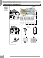
Air Source heat Pump
Air and
Source
Heat Pump
Installation
Maintenance
Manual
Installation Manual
Model numbers:
Model 4kW
numers:
KHP0041:
Heat Pump
KHP0038:
6kW 6kw
Heat Heat
PumpPump
KHP0038:
KHP0039:
8kW 8kw
Heat Heat
PumpPump
KHP0039:
KHP0040:
12kW
Heat
Pump Pump
KHP0040: 12kw Heat
KHP0042: 15kW Heat Pump
A9317D
22
Air / Water Cycle Heat Pump
Contents
R-410A - General info
Safety procedures
Dimensions and clearances
Installation & Technical data
Water connections
Electrical connections
Connection of Auxiliary Accessories
System test
Unit protection devices
Additional System Diagrams
Installation Pack
Optional Installation Accessories
7 day hot water programmer
Programmable room stat
Spare Part List
Rating Tables
Maintenance.
Page
INSTALLATION
4
6
8
10
12
20
22
24
26
29
36
41
43
55
71
75
80
SITING THE UNIT
WATER CONNECTIONS
ELECTRICAL CONNECTIONS
CONTROL WIRING (OPTIONAL)
POWER WIRING
FLUSHING WATER AND AIR
CHECKING FOR WATER LEAKS
CONFIGURING & CHECKING THE SYSTEM
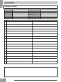
Code
Description
KHP0041
AEROMAX PLUS 4KW
KHP0038
AEROMAX PLUS 6KW
KHP0039
AEROMAX PLUS 8KW
KHP0040
AEROMAX PLUS 12KW
KHP0042
AEROMAX PLUS 15KW
33
Introduction
The information in this manual is to provide general
assistance in the selection of equipment. The
responsibility for the specification of the equipment must
however remain that of the installer and any consultants
or designers concerned with the installation, specification
or design.
Please note: Kingspan Renewables do not accept any
responsibility for matters of specification, design or
selection or for the effectiveness of an installation
containing one of our products unless we have been
specifically requested to do so.
Important Note - Included in the Aeromax Plus
introduction pack is the Kingspan Renewables 2-year
extended warranty registration card. Please use this card
to register within 30 days of commissioning/occupation if
new build, and ensure the homeowner benefits from the
extended warranty. This needs to be completed by both
Building Regulations
the Approved Installer and the current homeowner (or a
I.E.E. Requirements for Electrical Installations (BS7671) signature of developer is required if new build). The
registration card is free post and is logged by our warranty
Water Regulations Manual Handling Operations
department.
Regulations
Any water distribution and central heating installation
must comply with the relevant recommendation of the
current version of the Regulations and British Standards
listed below:
In the unlikely event of failure of the Aeromax Plus heat
British Standards BS6798, BS5449, BS5546,
BS5440:1, BS5440:2, CP331:3, BS6700, BS7593 and pump, return of the card ensures that the homeowner’s
warranty claim is dealt with efficiently.
BS7671. Health and Safety Document No 635.
When installing unvented hot water systems section G3 of All goods are sold subject to our Conditions of Sale (see
Web site for details).
the Building Regulations should be adhered to. An
annual inspection would also be required to ensure safe,
long term operation.
R-410A - General info
• This heat pump adopts the new HFC refrigerant
(R410A) which does not destroy ozone layer.
• R-410A refrigerant operates at 50%-70% higher
pressures than R-22. Be sure that servicing equipment
and replacement components are designed to operate
with R-410A.
• R-410A refrigerant cylinders have a dip tube which
allows liquid to flow out with the cylinder in a vertical
position with the valve at the top.
• R-410A systems should be charged with liquid
refrigerant. Use a commercial type metering device in
the manifold hose in order to vaporize the liquid
refrigerant before it enters in the unit.
• As for other HFC, R-410A refrigerant is only
compatible with oils recommended by the compressor
manufacturer.
• A vacuum pump is not enough to remove moisture
from oil.
• Oils absorb moisture rapidly. Do not expose oil to
atmosphere.
• Never open system to atmosphere while it is under
vacuum.
• When the system must be opened for service, break
vacuum with dry nitrogen and replace filter driers.
• Do not vent R-410A into the atmosphere.
Use this unit only for factory approved applications.
The capacity and unit code are stated on the nameplate
data.
CAUTION:
• Do not leave the heat pump casing open to atmosphere any
longer than the minimum required for installation.
• Oil in the compressor is extremely susceptible to moisture
absorption.
• The maximum residual quantity of oil used for tubing is 40
mg/10m.
4
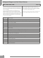
Unit protection devices
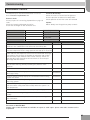
Introduction
Check List
The following check list has been prepared to assist you in
understanding the differences from other types of heating
systems you may have installed and help to understand
and comply with all of the technical details contained
within this document to ensure a successful installation.
System cleaning and Water Characteristics
• In the case of a new installation, or cleaning the circuit,
it is necessary to perform a preventive cleaning of the
system. In order to guarantee the good operation of the
product, each time you clean the system, replace the
water or add glycol, check that the liquid appears clear,
without visible impurities and that the hardness is less
than 20°f
• To help protect the heat pump from any heating system
contamination; the system filter should be fitted
internally on the return pipe.
Recommended system cleansers and inhibitors are listed
below.
Fernox F3 System Cleanser
Fernox HP-15c combined antifreeze and inhibitor
Sentinel
Radiator System Circuit
• As the Aeromax Plus generates lower temperatures
than a conventional boiler the radiators should have
been designed to suit the lower mean temperature.
• The basic controls within the standard installers pack
and the parameters on the heat pump are optimised
for use on radiator systems.
Retrofit Situations
• The heat exchanger should be protected from
particulate contaminates in the water circuit. The
existing radiator circuit must be chemically cleaned
and thoroughly flushed before installation when fitting
in a retrofit situation.
NOTE
NOTE
All external connecting pipe work should be suitably
insulated using Armaflex or similar.
For systems using under floor heating, boiler
back up or clients wishing to alter the
operating parameters of the unit; we
recommend the purchase of our advanced
controller. See manual for product code
KHP0008.
It is the installer’s responsibility to ensure
correct sizing and provision of both the
domestic circulating pump & any associated
central heating expansion vessel
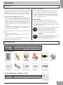
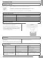
Installation Pack
The following items are required for the installation of the Aeromax Plus Air Source Heat Pump
Product Code
KHP0029
KHP0030
KHP0026
Description
4kW, 6kW & 8kW Installation Pack
12kW Installation Pack
15kW Installation Pack
Pack Contents
2 x 750mm flexible
hoses including 90°
elbow, pre-insulated.
Diagnostic indicator
1 x System filter
W Plan diverter valve
(heat pump specific)
Flow setter
Programmable room stat
Flush & fill ports
(except 15kW)
7 day hot water
programmer
Anti vibration pads
Immersion Heater
Controller
2 x Full bore isolating
valve with lever arm
System Antifreeze / Inhibitor - Clear
Product Code
KHP0023
Description
1 x 25 litre system antifreeze inhibitor - Clear
25L Heat Pump
Anti Freeze
Concentrate
1 x 25 litre clear - system
antifreeze inhibitor
5
Safety procedures
Important safety information is displayed on the product and in this Manual. Please read this
installation manual carefully before installing the unit. It contains further important
instructions for proper installation.
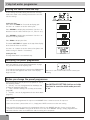
Explanation of illustrated marks
!
Indicates prohibited items.
Indicates mandatory items.
!
Indicates cautions (including danger/warnings).
Explanation of indications
DANGER
WARNING
CAUTION
Indicates contents will cause death
or serious injury if used incorrectly.
Indicates contents could cause
death or serious injury if used
incorrectly.
Indicates contents could cause an
injury or damage to property,
furniture or pets if the instructions
are not followed carefully.
General notes
• Please ensure this manual is read thoroughly and kept
for future reference.
• Before any repairs or maintenance are carried out an
assessment of the potential risks must be undertaken,
and appropriate measures taken to ensure the safety of
all personnel.
• Do not attempt to repair, move, modify or re-install the
unit on your own.
• Ideally a fully qualified competent MCS installer (such
as those registered under the micro certification scheme)
with prior knowledge of air to water heat pumps should
be used to install and/or commission the unit.
• All of the manufacturing and packaging materials used
for your new appliance are environmentally friendly and
can be recycled.
LIABILITY The manufacturer declines any liability
and invalidate the unit warranty for damage resulting
from:
• Improper installation; including failure to follow
instructions in the manuals.
• Modifications or errors in the electrical or
refrigerant or water connections.
• Unapproved units coupling; including other
manufacturers units.
• Use of the unit under condition other than those
indicated.
Units handling
!
!
!
!
Ensure adequate personal protective equipment is used.
Inspect equipment for damage due to improper transportation or handling: file an immediate claim with
the shipping company.
Dispose of the packaging material in accordance with local requirements.
When lifting the unit, absolutely do not use hooks inserted in the side handles, use special equipment
(e.g. lifting devices, trolleys etc.).
Do not step or put anything on the indoor/outdoor unit. It may cause an injury or damage the unit.
Do not place containers filled with liquids or other objects onto the unit.
This appliance must not be used by persons (and children) with reduced physical, emotional or
mental faculties or by persons with no experience or knowledge if they are not under the control of
a person responsible for their safety, or if not instructed to the use of this appliance. Make sure
that children do not play with the appliance.
6
Safety procedures
Unit installation
The installation must be carried out by a qualified
installer.
DO NOT INSTALL IN A PLACE...
• Difficult to access for installation and maintenance.
• Too close to heat sources.
• That might increase the vibration of the unit.
• Which cannot bear the weight of the unit.
• Subject to a risk of exposure to a combustible gas.
• Exposed to oils and vapours.
• With particular environmental conditions ie windy
location.
!
•
•
•
•
•
CHOOSE A PLACE...
Where noise and discharged air do not disturb neighbours.
Protected from strong winds.
That allows for the clearances required.
Which will not obstruct passageways or doors.
With floor structure adequately strong to support unit
weight and minimize vibration transmission.
!
Note...
Fix the unit with locally purchased bolts buried in the block.
If the unit is installed in areas where heavy snowfalls may
occur, it is necessary to raise its level at least 200mm above
the usual snow level or alternatively to use the outdoor unit
wall mounting bracket kit. See Kingspan optional extras
such as the “snow feet” (Anti vibration foot KHP0044 )
recommended for exposed areas to help create an air gap
under the unit.
Electrical connections
All field electrical connections are the responsibility of
the installer.
DANGER
Electrical shock can cause severe personal injury
or death. These operations are to be carried out by
qualified personnel only.
!
WARNING
• This unit complies with Machinery Directive
(2006/42/EC), electromagnetic compatibility
(2004/108/EC) and pressure equipment (EEC/97/23)
Directives.
• To avoid electric shock or fire make sure these
operations are carried out by qualified personnel only.
• Ensure that national safety code requirements have been
followed for the main supply circuit.
• Follow all current national safety code requirements.
• Ensure that a properly sized and connected ground wire
is in place.
• Check that voltage and frequency of the mains power
supply are those required; the available power must be
adequate to operate any other possible appliances
connected to the same line.
• Check that the impedance of the mains power supply is
in conformance with the unit power input indicated in
the rating plate of the unit.
• Make sure that properly sized disconnecting and safety
switches are installed.
• The disconnection devices from the mains supply must
allow full disconnection under the conditions provided
for by overvoltage class III.
CAUTION
• Connection to the mains supply is of the Y type;
therefore, the cable must only be replaced by a
qualified technician in order to prevent any risk.
• Use the specified cables for wiring and connect them
firmly to the terminals.
WARNING
• Be sure to provide grounding; inappropriate grounding
may cause electric shock.
• Do not connect ground wires to gas pipes, water pipes,
lightning rods or ground wires for telephone cables.
DANGER:
Do not modify this unit by removing any of the safety
guards or by by-passing any of the safety interlock
switches.
FINAL CHECK
!
WARNING
• If refrigerant gas leaks out during the installation work,
ventilate the room immediately.
• If refrigerant gas leaks into the room and flows near a
fire source, such as a cooking range, poisonous gas is
generated.
!
•
•
•
•
Contact the manufacturer if one of the following
events takes place:
hot or damaged power supply cable;
unusual noise during operation;
frequent operation of the protection devices;
unusual smell (such as smell of burning).
• Connect the connecting cable correctly. If the
connecting cable is connected in a wrong way, electric
parts may be damaged.
7
Safety procedures
!
CAUTION
!
CAUTION
• Ensure adequate personal protective equipment is used. • This equipment contains refrigerant that must be
disposed of in a proper manner.
• Extraordinary maintenance operations must be carried
• When disposing of the unit after its operational life,
out by specially trained personnel.
remove it carefully.
• The unit must then be delivered to an appropriate
Disconnect the mains power supply prior to any
disposal centre or to the original equipment dealer
! maintenance operations or prior to handling any
for proper environmentally compatible disposal.
internal parts of the unit.
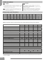
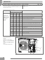
Dimensions and Clearances
A
B
C
D
E
F
G
H
L
KHP0041
908
821
326
350
87
356
466
40
60
weight
56
KHP0038
908
821
326
350
87
356
466
40
60
58
KHP0039
908
821
326
350
87
356
466
40
60
68
KHP0040
908
1363
326
350
174
640
750
44
69
99
KHP0042
908
1363
326
350
174
640
750
44
69
124
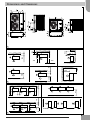
Minimum installation clearances in mm are shown in fig. 2 (single installation) and fig. 3 (serial installation)
Note: The height of the obstacle at both front and rear side should be lower than the height of the outdoor unit.
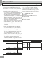
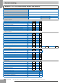
Specifications
KHP0041
4kW
KHP0038
6kW
KHP0039
8kW
KHP0040
12kW
KHP0042
15kW
4.1
1.01
4.35
4.05
A
5.8
1.37
5.95
4.24
A
7.2
1.82
7.91
3.95
B
11.9
3.01
13.1
3.94
B
14.5
3.57
15.5
4.06
A
3.9
1.22
5.3
3.2
A
5.8
1.90
8.26
3.06
B
7.4
2.32
10.1
3.18
B
12.9
4.26
18.5
3.03
B
14
4.36
18.9
3.21
A
Water pressure drop, kPa (Condition 1)
Fan Power Input (kW) (Condition 1)
Fan Speed (RPM) (Condition 1)
Current Input (A) (Condition 1)
Sound power level, heating‡ dB(A)
Sound pressure level, heating‡ dB(A)
16
0.09
680
0.65
62
42
9.5
0.09
680
0.65
62
42
14.5
0.099
680
0.85
64
44
26
0.191
710 - 730
1.63
67
47
33
0.19
780-820
1.18
68
48
Nominal Flow Rate (l/min)
Nominal Flow Rate (l/min) (Radiators)
Minimum Flow Rate (l/min) (to operate flow switch)
Maximum Flow Rate (l/min)
12
8.0
5
15
16.8
9.8
8
20
19.8
10.8
8
25
34.8
21.0
8
40
41.4
31.7
8
50
1195
1350
1810
2450
Ester Oil VG68
Rotary DC Inverter Technology
0.8
0.8
1
2.3
1" ISO228 (BSP) Male
300
(EN14511) – Packaged Monobloc.
3385
Data at Condition 1: A 7db/6wb W30/35 (EN14511)
Nominal heating capacity kW
Power input kW
Current Input (A)
COP (kW/kW)
Eurovent class, heating
Data at Condition 2: A 7db/6wb W40/45 (EN14511)
Nominal heating capacity (kW)
Power input (kW)
Current Input (A)
COP (kW/kW)
Eurovent class, heating
Refrigerant Content (g) R410A
Oil Type
Compressor Type
Net Water Volume (L)
Water Connections
Maximum Water Pressure (kPa)
Product Category
2.3
Above data applies to new, clean heat exchangers
Factory defult settings for heating are 55°C flow temp. To alter this you will be required to purchase the advanced
controller KHP0008
8
Dimensions and Clearances
150
150
500
200
1
300
1000
150
150
1000
500
100
300
300
300
300
300
1000
200
150
1000
200
2
1000
300
1500
2000
200
3
9
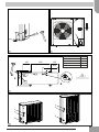
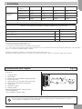
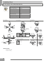
Installation
Before installation, check strength and levelness of the
base so that abnormal noise is not generated. According
to the dimensions and clearances, fix the base firmly
with the anchor bolts (Anchor bolt, nut: 4 off M10).
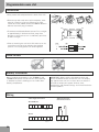
Opening cable knockouts
There is a pre-cut part that can be removed for running
wires. Do not remove the unit front panel for easier drilling
of the knockouts. The pre-cut section of the sheet can be
removed by punching the 3 connection points along the
line first using a screwdriver and finally with your hands
(See Fig. 4).
How to remove the front panel
1.Remove screws of the front panel (See fig. 5).
Drain hose and base pan knockouts
See fig. 6.
In case of draining through the drain hose, attach the
drain nipple (A) and use the drain hose (Inner diam:
16mm) sold on the market. When there is a possibility of
freezing of the drain in cold weather maintain a
continuous downward slope in the drain pipe to prevent
the drain becoming blocked by ice.
Operating limits
If the outdoor unit is installed in a very windy place,
protect the fan with a wind protection screen and check
that it works correctly.
(Fig. 4)
When the cable knockout is open, remove the burrs and
fit the cable protective bush supplied with the unit for
cable
(Fig. 5)
2. Pull the front panel downward with the handle.
(Fig. 6)
The drainage ability increases when knockout holes on
the base pan are opened. (Open the knockout hole to
outside using a hammer (B), etc.). Take care not to
damage the evaporator coil when opening the knockout
holes. We recommend that the knockout holes are opened
for all UK & Ireland installations.
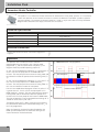
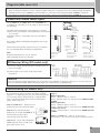
(Fig. 10)
Operation in heating: See fig. 10
A- Outdoor air temperature (°C)
B- Outlet water temperature (°C)
Radiator Design / Defrost Cycle
The Aeromax Plus system typically requires at least one
radiator (usually located in the same location as the room
thermostat) to remain “open circuit” with no thermostatic
radiator valve fitted.
For example:
8kW Aeromax Plus x 3ltr = 24 ltr of water to act as open
loop.
The minimum design criteria to be employed by the
installer is to allow 3 ltr per kW of nominal out of the heat
pump.
Circulating Pump
A circulating pump is not supplied as part of the
Aeromax Plus installation pack. A suitable circulating
pump must be specified based on the pressure loss in the
system.
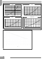
Climatic Curve
To qualify as a Weather Compensated heat pump the
Aeromax Plus is pre-programmed with a climatic curve.
See fig. 12.
10
(Fig. 11)
Pressure loss curves for the Aeromax Plus are shown in
fig. 11.
(Fig. 12)
Care must be taken to ensure this curve is suitable for
the application and heat emitters used. There are 12
pre-programmed climatic curves selectable using the
User Comfort Interface KHP0008. A custom climatic
curve can also be programmed.
4
5
Foundation Specification
150
600
150
430
Foundation bolt
M10 (3/8”)
Thickness of concrete
120mm
Length of bolt
70mm
Weight-bearing capacity
320kg
400
B
363
37
A
6
1
2
1
2
3
3
7
11
Water connections
Water Connections
(Fig. 8/9/11)
Make the plate heat exchanger hydraulic connections with
the necessary components, using material which will
guarantee that the screwed joints are leak proof. The
typical hydraulic circuit diagram shows a typical water
circuit installation in an air conditioning system.
For an application with a water circuit, the following
recommendations must be taken into account:
1. The pump must be fitted immediately before the heat
exchanger and after the connection to the system
return (unit without hydronic module).
2. It is advisable to install shut-off valves to allow
isolation of the most important circuit components, as
well as the heat exchanger itself.
These valves (ball, globe or butterfly valves) should
produce a minimum loss of charge when they are open.
3. Provide unit and system drains and vents at the lowest
and highest system points respectively.
4. Install purges in the higher sections of the installation.
5. Flow setter should be installed after the pump on the
return circuit. Leaving approx 200mm to avoid any
turbulence from the pump
6. All piping must be adequately insulated and
supported.
System cleaning and Water Characteristics
In the case of a new installation, or cleaning the
circuit, it is necessary to perform a preventive
cleaning of the system. In order to guarantee the
good operation of the product,each time you clean
the system, replace the water or add glycol, check
that the liquid appears clear, without visible
impurities and that the hardness is less than 20 °f
Fig. 8 - Integrated water circuit
1. Automatic valve with air vent
2. Flow switch
3. Pressure relief valve (300kPa, outlet 1/2’)
4.Temperature probe
Fig. 11
A - Water flow rate, (l/s)
B - Pressure drop (kPa)
Installation of the following components is obligatory:
1. The presence of particles in the water can lead to
obstructions in the heat exchanger. It is therefore
necessary to protect the heat exchanger inlet with a
filter or dirt separator. The filter mesh gauge must be at
least 10 mesh/cm2.
2. After assembling the system, or repairing the circuit,
the whole system must be thoroughly cleaned with
special attention paid to the state of the filters.
3. Flow rate control is made by the control valve on the
flowmeter/setter installed after the pump (see fig 9
item 11).
4. When water has to reach temperatures below 5°C, or
the equipment is installed in areas subject to
temperatures below 0°C, it is necessary to mix water
with inhibited monopropolyne glycol in a suitable
concentration.
Pipe water content
Internal Diameter
copper
steel
12
Unit
Outer diameter
Liters / meter
12 mm
14 mm
0,11 l/m
14mm
16 mm
0,15 l/m
16mm
18 mm
20mm
Aeromax Plus
4kw
6kw
8kw
12kw
15kw
Nominal water
flow
Std
l/s
0.2
0.28
0.33
0.58
0.69
Working
pressure
Max
kPa
300
300
300
300
300
0,20 l/m
22 mm
0,31 l/m
Filling pressure
Min
kPa
120
120
120
120
120
25mm
28 mm
0,49 l/m
Max
m
20
20
20
20
20
32mm
35 mm
0,80 l/m
Difference in
level with unit
at lowest level
12.7 mm (1/2'')" "
3/8'' Gas
0,13 l/m
16.3 mm (5/8'')" "
1/2'' Gas
0,21 l/m
21.7 mm (7/8'')" "
3/4'' Gas
0,37 l/m
27.4 mm (11/16'')" "
1” Gas
0,59 l/m
1
2
1
2
4
4
3
4
3
4
Integrated water circuit - Safety Devices
1 Automatic valve with air vent
2 Flow switch
3 Pressure relief valve (300kPa, outlet 1/2’)
4 Temperature probe
11
8
11
1
2
3
4
5
6
Isolating valves
System filter
Expansion vessel with PRV & Gauge (Robokit)*
Flush & Fill Ports
System drain valve (at lowest point ofsystem)*
Air purge (at highest points ofsystem)*
7 3-way valve
8 Hot water cylinder
9 Heating system
10 Circulating pump with isolating valves*
11 Flowmeter/setter
*not included in installers pack
LWT °C
9
70
70
65
65
60
60
55
55
50
50
45
45
40
40
35
35
30
30
25
25
20
20
15
10
15
20
10
-25
25
15
-20
30
-1535 -10 40 -5
450
5
50
10
15
10
20
25
30
35
OAT °C
10
8
13
30AWH004X
30AWH006X
6 kW
4 kW
70
65
55
60
50
55
45
50
40
B (kPa)
45
35
40
30
35
25
30
20
25
15
20
15
10
10
5
0
5
0
0
0,0
0,1
0,2
A (l/s)
0,3
0,1
0,2
0,3
0,4
0,5
0,6
0,5
0,4
30AWH012X
8 kW
30AWH008X
12 kW & 15 kW
60
40
50
35
30
40
25
30
20
15
20
10
10
5
0
0
0
11
12
8
14
0,1
0,2
0,3
0,4
0,5
0,6
0
0,1
0,2
0,3
0,4
0,5
0,6
0,7
0,8
0,9
Installation
% Inhibited Propyl- 10%
ene Glycol
Correction
Factors
20%
30%
40%
Freezing time (*)
-4 °C
-9 °C
-15 °C
-23°C
Capacity
0,996
0,991
0,983
0,974
Absorbed power
0,990
0,978
0,964
1,008
Loss of head
1,003
1,010
1,020
1,033
(*) Note: Temperature values are indicative.
Always refer to the temperatures indicated for the specific product used
TABLE TO USE FOR CALCULATING THE WATER CONTENT IN THE SYSTEM
Installed Unit
.............
Unit content (*)
l
.............
Pipe content (**)
l
.............
Uses (fan-coil, panels, radiators, etc.) (***)
l
.............
Total content (****)
l
.............
(*) Consult the technical data table.
(**) Consult the pipe water content table.
(***) Consult the manual from the relevant manufacturer.
(****) The water content of the system must be greater than the minimum value for units without hydronic kit. The minimum
value is necessary to provide optimal comfort.
Detailed installation schematics can be found at the back of the manual.
Should you require further technical assistance call your local office – details on the back page of this manual.
(Fig. 9)
Recommended water diagram
Typical water circuit diagram for Aeromax Plus unit
(see fig. 9)
1 Isolating valves
2 System filter
3 Expansion vessel with PRV & Gauge (Robokit)*
4 Flush & Fill Ports
5 System drain valve (at lowest point of system)*
6 Air purge (at highest points of system)*
7 3-way valve
8 Hot water cylinder
9 Heating system
10 Circulating pump with isolating valves*
11 Flowmeter/setter
*not included in installers pack
11
9
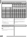
Do not use the heat pump to treat industrial process, swimming pool or sanitary water. In all these
cases, provide an intermediate heat exchanger.
15
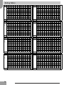
Aeromax Plus Expansion Vessel Sizing – Sizing Examples
Maximum Working Temperature
30
40
50
60
70
80
90
Coefficient of Fluid Expansion with respect to 10°C (30% Glycol/
Water)
0.00272 0.00499 0.00779 0.01108 0.0148 0.01891 0.02336
Pre-charge
Max System Pressure System
Pressure
(Pressure Relief Valve Volume
(Air side of vessel) Rating)
(Litres)
Approximate Expansion Vessel Volume Required (Litres) as a
Function of the Max Working Temperature
0.5
1
100
1.1
2
3.1
4.4
5.9
7.6
9.3
0.5
1.5
100
0.7
1.2
1.9
2.8
3.7
4.7
5.8
0.5
2
100
0.5
1
1.6
2.2
3
3.8
4.7
0.5
2.5
100
0.5
0.9
1.4
1.9
2.6
3.3
4.1
1
1.5
300
4.1
7.5
11.7
16.6
22.2
28.4
35
1
2
300
2.5
4.5
7
10
13.3
17
21
1
2.5
300
1.9
3.5
5.5
7.8
10.4
13.2
16.4
1
3
300
1.6
3
4.7
6.6
8.9
11.3
14
1.5
2
500
8.2
15
23.4
33.2
44.4
56.7
70.1
1.5
2.5
500
4.8
8.7
13.6
19.4
25.9
33.1
40.9
1.5
3
500
3.6
6.6
10.4
14.8
19.7
25.2
31.2
2
2.5
1000
19.1
34.9
54.5
77.5
103.6
132.4
163.5
2
3
1000
10.9
19.9
31.2
44.3
59.2
75.7
93.5
If the system details are outside of the range shown in
the table the expansion vessel size can be calculated
using the following formula:
V = e * C / {1-[ (Ppre + 1)/(Pmax + 1) ] }
Where:
e = Coefficient of Fluid Expansion with respect to 10°C
(30% Glycol/Water)
C = total System Volume (litres).
Ppre = Pre-charge Pressure (Bar)
Pmax = Max System Pressure (Bar)
Note: the required vessel volume will almost certainly
not correspond exactly to an existing size, therefore the
nearest available size above the value returned for V
must be selected from the available vessels in the
range.
The calculation is valid provided the expansion vessel
and the safety valve are at the same height. The
maximum system pressure for Aeromax Plus Heat
Pumps is 3 bar.
Cylinder Installation for Domestic Hot Water
We recommend the Kingspan Albion Aerocyl is used as it
has a heat pump specific coil fitted.
!
Note...
If the Aerocyl is used in conjunction with the 3 port valve
supplied with the Aeromax plus there is no requirement for
the additional 2 port valve.
16
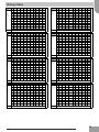
4, 6 & 8 kW
NOTE
No 2 port
required if
using with
heat pump
Water connections (Typical Schematic for Radiator System)
17
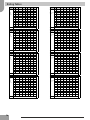
12 kW
NOTE
No 2 port
required if
using with
heat pump
Water connections (Typical Schematic for Radiator System)
18
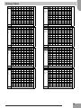
15 kW
NOTE
No 2 port
required if
using with
heat pump
Water connections (Typical Schematic for Radiator System)
19
Electrical connections
(Fig. 13)
!
All field electrical connections are the responsibility of the installer.
!
WARNING
Make water connections before electrical connections. Make ground connection prior to any other electrical
connections.
Unit
Aeromax Plus
Power Supply
KHP041
KHP0038
KHP0039
KHP0040
KHP0042
4kW
6kW
8kW
12kW
15kW
V - ph - Hz
230 - 1 - 50
Allowable Voltage Range
V
207/253
Maximum Power Drawn
kW
2
2.3
2.7
5.1
5.1
A
7.2
11
14
23
20
25 Type D
25 Type D
Maximum Current Drawn
Power Fuses
Type
Current (A)
Power Supply Cables
gL Type
10 Type B 15 Type B
mm2
Maximum Circulating Pump Current
A
15 Type B
H07RN-F 3 x 2.5mm2
2
Use cables H03VV-F 4x0.75 mm² to connect the control to
wire User Comfort Interface (KHP0008)
Remove the front panel, the electric parts appear at the
front side. The power supply cables can be inserted into
the holders. Be sure to fix the power cable with bundling
band sold on the market so that they do not make contact
with the compressor and the hot pipes.
To ensure good tensile strength, the electric cables must
be fastened using the cable-holder on the plate.
The unit can be controlled and set via:
• User Comfort Interface wire control KHP0008
(Optional)
• Aeromax Plus Controls Pack KHP0036/37
• Switches (not supplied)
For the electrical connections refer to wiring diagram,
while, for use, refer to the relative manuals.
Cables from Indoors – Heat Pump
2 x 3 core 240v
1 x 7 core for 0-12v
1 x 3 core mains to HP
Only for KHP0042 use the strain relief supplied with the
unit.
Wired control
For installation of wired remote controller please refer to the control installation manual.
Power supply
Size the cable, the cables must be H07RN-F type (3 x 2.5 mm2).
According to the installation instructions, all devices for disconnection from the power supply
mains must have a contact opening (4 mm) to allow total disconnection according to the
conditions provided for the overvoltage class III.
To prevent any risk, the power cable must only be replaced by the technicians of the after-sales
service.
20
Legend
DC (low voltage)
AC
Electrical connections
13
21
Auxiliary accessories connection
(Fig. 13)
3-way valve
The Aeromax Plus units drive a 3-way valve to manage a
Domestic Hot Water cylinder. The operating logic
provides that, in the case of a request for sanitary water
by a DHW cylinder, the system controls a 3-way valve to
direct the hot water only to the tank and to operate at
the maximum capacity to provide water at 60 °C
(compatible with the operating envelope).
The hot water request signal must be a Dry Contact type
(contact quality greater than 25mA @ 12V) that closes
the circuit between PINS 15 and 13 of the terminal strip
(see Fig. 13 page 21).
Attention: The hot water request has higher priority than
the programmed operating mode in heating.
Frequency Limitation
To force the unit to operate at a lower maximum
frequency (to reduce noise) in the absence of a User
Comfort Interface, provide a Dry Contact (contact quality
greater than 25mA @ 12V) between PINS 13 and 14 of
the terminal strip. With the contact closed, the unit will
operate with a maximum frequency lower than the
standard one, otherwise it will operate in standard mode.
For correct operation, it is necessary to configure the
unit using parameters 5 and 6 from the User Interface
menu of the KHP0008. The maximum noise reduction
is about 3dB at 75% of the maximum operating
frequency of the compressor
Stop Unit or Defrosting signals
There are several signals available on the terminal strip
to indicate particular conditions or the stop of the
external unit. The available signals are:
• Defrosting: When operating in Heating mode,
depending on the external environmental conditions,
the unit could perform defrosting cycles to clean the
external battery of any ice formations. Under these
conditions, it is not possible to guarantee the
requested temperature output water temperature,
which could reduce general comfort.
• Alarm: Indicates an alarm condition that stops the
compressor.
• Ambient Temperature Reached: If suitably
programmed using the User Comfort Interface, and
operating with this interface, a signal is provided that
indicates that the pre-set temperature has been
reached. This signal can be used as the contact
window normally implemented in the fan-coils.
Several outputs are used for more than one condition. It
is possible to configure these outputs through the User
Comfort Interface installation menu (refer to the
KHP0008 manual part number A9315). Refer to the
tables for the correct pin-outs and use of the signals.
External temperature probe
If the positioning of the external unit could induce a nonrepresentative reading of the external temperature by the
probe positioned on the machine, an additional remote
temperature probe can be provided (NTC 2 wire, 3kΩ @
25°C, Kingspan Part Number KHP0009). Connect the
terminals of the probe between PINS 23 and 24 of the
terminal strip (see Fig. 13).
Legionella Protection
Sanitization of the DHW cylinder is controlled by setting
the time on the 7 day programmer installed. To sanitise
the water in the cylinder set the hot water period to more
than 50 mins.
22
Example:
Heat pump programmed to heat water 4:00 am – 5:30
am. Heat pump will produce hot water for 50 mins to
approx 55°C. Immersion heater will activate for the
remaining 40mins to raise water temperature to 60°C+.
The immersion heater will stop when the immersion
heater thermostat activates.
Auxiliary accessories connection
Signal for requesting an External Heat Source or Dehumidification
Between PINS 4 and N of the terminal strip (see Fig.
13),there is an output (1ph ~ 230V, 2A max) that can be
programmed using the remote User Comfort Interface (see
the control manual, Installation Menu code 106). when
OAT < Temperature set in KHP0008 code 150 (but OAT >
temperature set in KHP0008 code 148). In this region
HP keeps working and backup heater turns on if set point
on water is not reached by 5°C (value can be set with
KHP0008 CODE 152) for 10 minutes (value can be set
with KHP0008 CODE 151). Backup heater turns off when
set point on water is reached again.
IMPORTANT NOTICE :
In case of SHW activation (pins 13-15 closed) heat pump
will turn on and backup heater will turn off. This will
happen in both the above strategies.
WARNING :
In case of EHS installation, it is mandatory to install a
thermal switch on the water circuit to protect the system
from too high water temperatures. This protection item
has to be located downstream from the EHS.
Additional water circulator for Aeromax Plus
It is possible to connect an additional water pump
through the pins 12 and N. It is managed in the
following way:
If OAT > temperature set in KHP0008 code 148
The additional water pump activation depending on the
setting of KHP0008 code 156
1.ON/ OFF depending on the outdoor unit water pump
logic, in case of SHW activation ADD WP is ON;
2.ON/ OFF depending on the outdoor unit water pump
logic, in case of SHW activation ADD WP is OFF;
If OAT < temperature set in KHP0008 code 148
The additional water pump activation depends on the
setting of KHP0008 code 157 (0. always ON, 1. always
OFF or 2. ON/OFF depending on EHS).
External Alarm Input
On PIN 21 of the terminal strip (see Fig. 13) an alarm
input (dry contact) is available to force off the unit.
When the contact is closed (Pin 21 active) the whole
system is turned OFF (Unit OFF, WP OFF, GMC alarm n°
2). When the dry contact open the system turns ON and
works in the last configuration.
It is possible to use this feature connected with different
external control systems and/or safety devices. For
example in case of danger an external safety device could
send an output alarm signal to close the contact. So the
outdoor unit turns off and remains in that condition until
the dry contact is reopened.
Terminal Strip Pin Layout
Aeromax Plus
Description
PIN
Signal
Additional external
temperature
23 24 Input (NTC 3kΩ @25°C) N.A. 126
Sanitary Water Request
switch
13 - 15
Input (contact
N.A.
N.A.
Maximum Frequency
Reduction
13 - 14
switch
Input (contact
N.A.
N.A.
3-way valve
10 - 18 - N
Output 230Vac (18-N:
Power supply, 10
1 ph ~ 230V, 2A N.A.
Relay Output Contact
1 ph ~ 230V, 2A 106 - 148 -150 -151 - 152 -154 -155
5- N
Relay Output Contact
1 ph ~ 230V, 2A 147
11 - N
Relay Output Contact
1 ph ~ 230V, 2A 107 - 108
12 - N
Relay Output Contact
1 ph ~ 230V, 2A 156 - 157
21
Input (contact switch
quality >25mA@12V)
N.A.
External Water Circulator
16 - N
Relay Output Contact
1 ph ~ 230V, 2A N.A.
NORMAL / ECO Mode
8-3
Dry contact
N.A.
1- External Heat Source Request 4 - N
Limits
KHP0008 Installation Menu
2- Defrost
1- Alarm
2- Ambient temperature reached
1- Alarm + defrost
2-Humidifier
1- Trace heater
2-Additional WP
Alarm input
N.A.
N.A.
Note: The maximum total instantaneous current must be less than 3.5A. In the case of loads with higher
absorbed current, it is necessary to drive the loads with relays to be inserted between the power supply of the
load itself and drive the relays from the terminal strip.
23
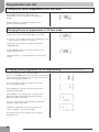
System test
Inverter board alarm codes KHP0040 12kW unit only
Faults of the inverter can be diagnosed by LED indications
on the cycle control P.C. board of the outdoor unit. Utilize
them for various checks.
(Fig. 14)
Before a check, confirm each bit of the DIP switch is set
to OFF position.
LED indication and code checking
LED indication
Cycle control P.C. board
Cause
LED indication
D800 O: Red
D801 O: Yellow
D802 O: Yellow
D803 O: Yellow
l: Flashing
t: Off
¢: On
D800
D801
D802
D803
¢
l
l
l
Heat exchanger sensor (TE) error
l
l
l
Suction sensor (TS) error
¢
¢
l
l
Hot gas discharge sensor (TD) error
l
¢
l
¢
High-pressure protection error
l
¢
l
l
Outdoor air temperature sensor error (TO)
¢
¢
¢
l
Outdoor motorised fan error DC
¢
l
l
¢
Communication error between IPDU (Abnormal stop)
l
¢
l
¢
High-pressure release operation
l
¢
¢
l
Discharge temp. error: hot gas is too high
¢
¢
l
¢
EEPROM error
l
l
¢
¢
Communication error between IPDU (No abnormal stop)
t
l
l
l
G-Tr short-circuit protection
l
t
l
l
Detect circuit error
l
t
l
l
Current sensor error
l
l
t
l
Comp. lock error
t
l
t
l
Comp. break down
¢
Board position Fig. 14
Legend:
A Position 4 LED Inverter
Diagnostics Board (KHP0040/42
only)
B Position LED GMC Diagnostics
Board
C Installation terminal strip
A
C
B
14
24
System test
Inverter board alarm codes (only for KHP0042 15kW unit)
The error which is generating at present and the latest
error (Latest error information including present) can be
confirmed by lighting LED D800 to D804 on the outdoor
control P.C board.
a) When all DIP switch SW803 are OFF, the status of
error which is generating at present is displayed.
b) <1> only of DIP switch SW803 is turned on, the error
which generated before (latest error information
including present) is displayed.
4
3
l
l
¥
l
l
¢
1
ON
2
1
ON
c) If there is an error, any of LED D800 to D804 goes
on. (Display 1)
d) When pushing the pushdown button switch SW800
for approx. 1 second, the display is exchanged.
(Display 2)
e) When pushing SW800 again or after 2 minutes, the
status returns to that of Display 1.
Legend
2
4
Latest error
SW803
3
Present error
SW803
(Fig. 14)
D800
D801
D802
D803
D804
D805
(Yellow)
(Yellow)
(Yellow)
(Yellow)
(Yellow)
(Green)
l: Go off, ¢: Go on, ¥: Flash
Display 1
(Initial Display)
Display 2
(SW800 operation)
lllll¢
lllll¢
Normal
ll¥ll¢
Discharge temp. sensor (TD) error
l¥¥ll¢
Heat exchanger temp. sensor (TE) error
¥¥¥ll¢
Heat exchanger temp. sensor (TL) error
lll¥l¢
Outside temp. sensor (TO) error
ll¥¥l¢
Suction temp. sensor (TS) error
¥l¥¥l¢
Heat sink temp. sensor (TH) error
¥¥¥¥l¢
Heat exchanger sensor (TE, TS) error
¥¥¥¥¥¢
EEPROM error
¥llll¢
Compressor break down
l¥lll¢
Compressor lock
¥¥lll¢
Current detection circuit error
ll¥ll¢
Case thermostat operation
l¥l¥l¢
Model unset
¥l¥¥¥¢
Communication error between MCU
¥¥¥¥¥¢
Other error (compressor disorder ect.)
¥¥lll¢
Discharge temp. error
¥l¥ll¢
Power supply error
¥¥¥ll¢
Heat sink overheat error
¥¥¥¥l¢
Gas leak detection
¥¥ll¥¢
4-way valve reverse error
ll¥l¥¢
High pressure protective operation
l¥¥l¥¢
Fan system error
l¥l¥¥¢
Driving element short-circuit
¥l¥¥¥¢
Position detection circuit error
¢¢ll¢¢
ll¢l¢¢
l¢¢l¢¢
¢¢¢l¢¢
Error contents
25
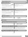
Refrigerant Diagram and Unit Protect Devices
GMC Board Alarm Codes
There is an LED on the GMC board that displays any board
errors. The error code can be identified from the flashing
LED using the following table. In the case of more than one
error, the error with the highest priority will be displayed
until it is resolved.
In the case of normal operation, the LED flashes at a
frequency of 0.5 Hz. In the case of an error, the LED
remains off for 4 seconds, then at a frequency of 1Hz, it
flashes a number of times equal to the error code and than
remains off again for 6 seconds. If the error code has 2
digits, the flashing is interrupted for 2 seconds between
the first and second digits.
(Fig. 14)
Example: error 23: LED off for 4 seconds. 2 flashes at a
frequency of 1Hz. Off for 2 seconds. 3 flashes at a
frequency of 1Hz. Off for 6 seconds. The cycle repeats
until the LED turns off because the problem is resolved
or if an error with higher priority occurs.
To reset the unit after an error has been cleared turn off
the mains supply for 10 seconds and turn on again.
Fault Code
Code Description
2
Safety Input
3
Enter Water Temperature Sensor (EWT) Failure/Out of Range
4
Actual Refrigerant Temperature Sensor BPHE (TR) Failure/Out of Range
5
Outdoor Air Sensor of GMC
6
Loss communication to NUI control
7
NUI control Room Sensor
8
Unit Capacity Mismatch
9
Flow Switch error / Water Pump
10
EEProm Corrupt
13
Loss Communication to RS485 (system configuration type 6)
14
Loss of Signal From inverter board/High Temperature Release (Thermostat on compressor: 120°±4°C)
15
Exit water Temperature Sensor (LWT) Failure/Out of Range
17
Inverter Air Sensor (TO) Failure/Out of Range
18
G-Tr inverter short circuit protection
20
Compressor position Detection Circuit error
21
Inverter Current Sensor error
22
Heat Exchanger Sensors (TE) / (TS) Failure/Out of Range
23
Discharge Temperature Sensor (TD) (TD > 100° ± 4° C)
24
Outdoor Fan motor error
26
Other inverter board error
27
Compressor Lock
28
Discharge Temperature error Failure/Out of Range
29
Compressor Breakdown
26
A
A: 4 way valve
B: DC Rotary Compressor
C: BPHE
D: Pulse Motor Valve
E: Distributor
F: Fan
G: Heat Exchanger
HTT: High Temperature Thermostat
T1: TS sensor
T2: TD sensor
T3: TR sensor
T4: TE sensor
T5: TO sensor
Ta: EWT sensor
Tb: LWT sensor
B
G
F
E
15
D
Type of Safety Device
C
Operating Condition
Pressure Relief Valve ( Water side - see Fig 8) 300 kPa
Flow Switch ( Water side - see Fig 8)
> 8 l/min
Release/Reset
Self Reset
< 6 l/min
High Temperature Thermostat (see Fig 15)
> 120 °C
< 90 °C
Refrigerant Temperature Sensors (Fig 15 T1 to "Failure/Out of Range ( Operating In Range
T5)
range depends on sensor
location)"
Water Temperature Sensors (Fig 15 Ta & Tb)
T < 0 °C, T > 70 °C
0 °C ≥ T ≤ 70 °C
Anti-Freeze Protection (Fig 15 T5)
Compressor Start Acceleration limit
Adjustable from 2 to 6 °C
6 accelerations/hr
Software controlled
N/A
Delayed Compressor Start (OFF - ON)
180 secs (max)
N/A
Delayed Compressor Stop (ON - OFF)
180 secs
N/A
!
IMPORTANT
During functioning in heat pump heating mode, the unit performs defrost cycles to eliminate any ice that might
form at low temperatures inside the outdoor unit
Refrigerant charge check
This check becomes necessary after any refrigerant leak
or after replacement of the compressor. The best method
to correctly charge refrigerant is to completely empty the
refrigerant circuit using refrigerant recovery equipment.
Then charge the exact quantity of refrigerant according to
the data shown on the unit nameplate and always
considering the additional charges listed on the charge
sheet.
R-410A systems must be charged with liquid refrigerant.
Use the special recharging equipment (normally on the
market) to control the refrigerant correctly.
!
IMPORTANT
Any works carried out on the refrigerant circuit
must be undertaken by a person holding the
relevant Fgas certification
27
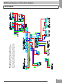
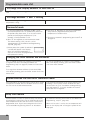
Note: Where an open heating circuit has not been
installed or where the system flow rate falls below the
minimum required level when the zone valves close a
bypass valve must be installed.
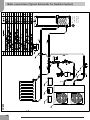
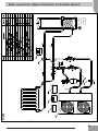
Additional Systems: Twin Zone System.
Water connections
28
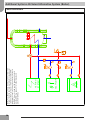
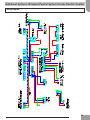
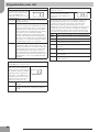
Note: Where an open heating circuit has not been
installed with sufficient volume required for the defrost
cycle the output from PIN 11 should be connected as
shown to enable the heat pump to open a heating circuit
during the defrost cycle. Parameter 108 must be set to 1.
Additional Systems: Twin Zone System.
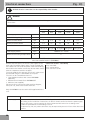
Wiring Diagram
29
30
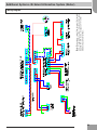
BOILER
HEAT PUMP
HEATING
SYSTEM
Note: On a request for DHW production the boiler will be
turned off and the heat pump activated. In severe weater
conditions this may impact comfort levels and the DHW
temperature. In this case it may be necessary to turn off
the DHW time clock and use the immersion heater to
provide DHW. See page 23 for further details and
parameter settings.
Additional Systems: Bi-Valent Alternative System (Boiler).
Water connections
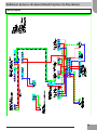
Note: The maximum current from terminal 4 is limited
to 2A. If required the heating circulation pump may be
supplied from terminal 12. See page 23 for further
details and parameter settings.
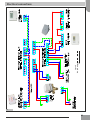
Additional Systems: Bi-Valent Alternative System (Boiler).
Wiring Diagram
31
32
HEAT PUMP
HEATING
SYSTEM
Note: On a request for DHW production the Inline heater
will be turned off and the heat pump activated. In severe
weater conditions this may impact comfort levels and
the DHW temperature. In this case it may be necessary
to turn off the DHW time clock and use the immersion
heater to provide DHW. See page 23 for further details
and parameter settings.
IN LINE
ELECTRIC
HEATER
Additional Systems: Bi-Valent Parallel System (In-line Electric Heater)
Water connections
Additional Systems: Bi-Valent Parallel System (In-line Electric Heater)
Wiring Diagram
33
Additional Systems: Bi-Valent Retrofit System (S-Plan Boiler)
34
HEAT PUMP
HEATING
SYSTEM
BOILER
Water connections
Additional Systems: Bi-Valent Retrofit System (S-Plan Boiler)
Wiring Diagram
35
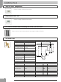
Installation Pack
7 day hot water programmer
Please see page 43 for full instructions
Programable room stat
Please see page 55 for full instructions
2 x 750mm flexible hoses including 90°elbow, pre-insulated
Used to connect flow & return pipes to heat pump and reduce vibration
1 x system filter
Drawing:
Water / glycol (max.50%)
Max. Flow velocity:
1 m/s
Max. volume:
0.30 l/s
Max. System pressure:
6 bar-g
Max. temperature:
110 °C
Design rules:
Standard
m
L
Hv
Medium:
Hh
Design parameters:
Quality rules:
Leakage tests
yes
Testing certificate:
no
Design and Production
according 97/23/EC:
d
Ø54
yes
Material certificates:
no
Drawing:
yes
Construction materials
Dimensions:
Housing
brass
d
22
mm
Connection nut
brass
Hv
167
mm
Swivel h/v
brass
Hh
149
mm
Drain ball valve
brass
L
100
mm
Spiro-tube:
core-tube - copper
m
102
mm
Volume:
0.18
ltr
wiring - copper
solder - tin(SnCu3)
36
Magnet:
ferrite
Weight (empty) appr.
1.44 Kg
Rights of modification reserved
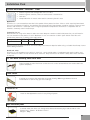
Installation Pack
System Antifreeze / Inhibitor - Clear
25L Heat Pump
Anti Freeze
Concentrate
•
•
•
•
Protects against frost damage from -14°C to -34°C
Protects against corrosion, limescale and bacterial contamination
Non-toxic
Compatible with all metals and materials commonly found in heat
Application
Fluid Plus is a concentrated heat transfer fluid capable of frost protection from -14°C to -34°C especially formulated
for use in Heat Pumps. Fluid Plus also provides long term protection from damage caused by corrosion, limescale and
bacteria and maintains a stable pH across a range of operational temperatures. Fluid Plus is compatible with all
materials commonly used in Heat Pumps.
Instructions for use
Dilute before use using mains water. In order to ensure adequate corrosion and biocidal protection, the minimum ‘inuse’ concentration of the product is 33%. Maximum ‘in-use’ concentration is 50%. Upon dilution Fluid Plus will
provide frost protection according to the table below.
Concentration
Frost Protection
33%
-14°C
40%
-22°C
50%
-34°C
Existing heating systems should be cleaned of sludge and limescale deposits before using a suitable Heat Pump cleaner
before adding Fluid Plus.
Health and safety
Fluid Plus is non hazardous but as with all chemicals, care should be taken. If swallowed seek medical advice and
show container or labels. Do not mix with other chemicals. Keep out of reach of children. Safety data sheets available
on request.
2 x Full bore isolating valve with lever
To be installed on end of flexi hose so that the unit can be isolated without the need to drain the
system completely
Flow Setter
Installed on the return pipe work after the pump allowing 200mm gap between them to
avoid turbulence (which may give false readings)
Flush & Fill
Install on flow pipework to assist in easy filling of system
Anti vibration pads
Installed under feet of the unit. Designed to withstand extremely high loads & reduce noise.
Dimensions L 76mm x W 76mm x D 22.2
Weight = 100g
37
Installation Pack
W Plan diverter valve (heat pump specific)
Operating voltage
230VAC
Switch current rating
3 (1) A
Switch action
Type 1B
Max temperature
45°C
Enclosure rating
IP40
Pollution situation
Degree 2
Ball pressure temp
75°C
Open/close time
30/10 sec
Rated impulse voltage
2.5K
Cord attachment
Solder 2 crimp
3.0 Installation
4.0 Assembly
5.0 Operation
Auto
Manual
IMPORTANT
Tighten evenly
û
Not potable water
T
- 10°C Min,
95°C Max
è
L
(Brown)
N
(Blue)
* Shown de-energised
B
ü
A
è
AB
û
A
è
è
è
AB
B
AB
B
ü
A
è
è
IMPORTANT NOTE:
Port A to hot water
Port B to heating
A
è
é
B
2.0 Wiring - HSA3ND
M
16bar
max
HSA3ND
0.7
Electrically operated valve - Not for use with potable water
10bar max
PT
7.9
è
P1
28mm
1.0
è
è
Pv=P1-
6.8
Type
è
ç
ê Pv (bar)
6.1
22mm
P2
38
Kv (M3/h)
è
P2
Size
- 10°C Min, 45°C
AB
û
Installation Pack
Diagnostic Indicator
Read the following instructions before starting the installation.
This product is a Diagnostic Indicator for Aeromax Plus heat pump models. It
indicates the alarm and power status of the Aeromax Plus unit.
It must be connected to the Aeromax Plus unit for correct operation.
Technical specification
Dimensions
120mm (w) x 80mm (h) x 55mm (d)
Material
Polycarbonate
Ambient temperature
-25°C to +70°C
Nominal supply voltage
12V DC
Maximum supply voltage
20V DC
Cable
Minimum 0.5mm2, 3 core, shielded
Electrical connection
Before connecting any wiring to the diagnostic indicator,
turn the Aeromax Plus unit power off.
Use a minimum of 3 core cable to connect the
diagnostic indicator to the Aeromax Plus unit. Refer to
the wiring diagram below. If shielded cable is used the
shield should be grounded only on the Aeromax Plus
terminal strip (terminal no.3).
Diagnostics
Power LED (green) indicates that the Aeromax Plus unit is code table. Refer to the Aeromax Plus Installation Manual
powered ON.
for the alarm code explanation.
Alarm LED (red) indicates when an error occurs. The error
code can be identified from the flashing LED using a fault
Troubleshooting
Problem
Likely cause
Solution
Power LED off
1) Aeromax Plus unit is off
1) Check that the Aeromax Plus
power is connected.
2) Wires connected incorrectly
2) Switch the Aeromax Plus unit off
Check the wires.
3) There is no 12V coming from the
Aeromax Plus unit
3) Check the connection on
the Aeromax Plus unit.
1) Diagnostic indicator is damaged
1) Replace the diagnostic indicator
Wiring is correct and 12V applied
to the diagnostic indicator but the
LEDs are OFF.
39
Installation Pack
Immersion Heater Controller
Read the following instructions before starting the installation.
This product is an Immersion Heater Controller for Aeromax Plus heat pump systems. It is installed to
control the operation of the immersion heater to sanitise the Domestic Hot Water cylinder to prevent
Legionella growth. The Immersion Heater Controller is used in conjunction with the 7 Day Hot Water
Programmer to determine the day(s) and times for sanitisation.
Technical specification
Dimensions
180mm (w) x 110mm (h) x 87mm (d)
Material
Polycarbonate
Ambient temperature
-25°C to +70°C
Nominal supply voltage
220V - 240V AC
Maximum supply current
16A
Electrical connection
Please refer to the electrical connection diagram on
Page 21.
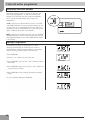
Operation
The operation of the immersion heater controller is
determined by the time setting in the 7 day hot water
programmer Ton and the internal timer relay delay Tr. The
diagram shows the possible operating sequences.
In part 1 of the DHW demand program Ton is greater than Tr.
In this case the heat pump will run in DHW mode for Tr
minutes. The heat pump will then revert to heating mode and
the immersion heater will operate for the remaining time (Ton Tr).
DHW Demand (From 7 day programmer)
On
Ton > Tr
The default setting for Tr is 50 ± 3 minutes. Please refer to
the Homeowners Guide for recommended settings for Ton on
the 7 day programmer.
Note: the immersion heater will be deactivated when the
DHW cylinder temperature rises above the setting of the
internal immersion heater thermostat.
40
Ton > 2Tr
Heating
Heat Pump Mode
In part 2 of the DHW demand program Ton is less than Tr. In
this case the heat pump will run in DHW mode for Ton
minutes. The heat pump will then revert to heating mode. In
this case the immersion heater will not operate.
Part 3 of the DHW demand program shows the effect if Ton
is greater than 2Tr. In this case the heat pump will run in
DHW mode for Tr minutes. The heat pump will then revert to
heating mode and the immersion heater will operate for Tr
minutes also. The heat pump will then return to DHW mode.
This type of operation is not recommended and timings for Ton
should set as for those in part 1 & 2.
Ton < Tr
Off
Tr
DHW
Tr
Immersion Heater Operation
On
Off
Tr
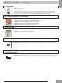
Optional Installation Accessories
Filling station
C0814 filling station.
The Kingspan Flushing & filling station aids the installer when commissioning the heating
system. It can be connected directly to the flush and fill port supplied in the installers pack
which in turn is then filled with the Kingspan antifreeze / inhibitor concentrate.
Wall mounting bracket & condensate
KHP0013 Wall bracket 90kg (fits 4kW, 6kW & 8kW units)
KHP0014 Wall bracket 140kg (fits 12kW & 15kW units)
KHP0016 Condensate tray for 4kW, 6kW & 8kW units
KHP0017 Condensate tray for 12W & 15kW units
Protective cage
KHP0011 Guard for 4kW, 6kW & 8kW units
KHP0012 Guard for 12W & 15kW units
Advanced programmable controller
KHP0008 Aeromax Plus advanced programmable controller. Required for changes to factory
parameter settings.
Anti-vibration foot
KHP0044 Installed under feet of the unit. Designed to withstand extremely high loads & reduce
noise
41
Optional Installation Accessories
External Temperature Sensor KHP0009
Ø 4mm
B036502H01
B036502H01
Ø 4mm
C W G Y
23 24 1
21 22 3 6
2x FROH2R
0.5 mm2
(max 50m)
7 8 2
û
û
min 2m
û
û
û
û
û
û
X = unsuitable location
42
û
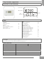
7 day hot water programmer
Installation & User Instructions
+1HR override
+1HR
MAN override
MAN
RESET
DAY/HO
L
Mode
SELECT
Index
Installation
Product specification
Installation
Wiring
DIL switch settings
Advanced Programming Options
Copy Functions
Service Interval Timer
43
44
–
–
45
–
46
User
What is a programmer?
Your timeswitch
Preset programmes
Before you start
AM/PM or 24hr display
Setting the Time and Day
Accepting the preset programmes
Changing the preset programmes
Programming system - 5/2 day
Programming system - 7 day
Programming system - 24 hour
Running the programme
Temporary overrides
Holiday Programme
Changing clocks forward/back
Service Interval Timer
Making a full reset
Troubleshooting
46
47
–
–
–
48
–
–
49
50
51
–
52
–
53
–
54
–
Please Note:
This product should only be installed by a qualified electrician or competent heating installer, and should be
in accordance with the current edition of the IEEE wiring regulations.
Product specification
Specification
Power supply
Switching action
230V Model
24V Model
230 Vac, ±15%, 50/60 Hz
24Vac, ±15%, 50/60Hz
1 x SPDT voltage free, Type 1B
Switch rating
24 - 230 Vac, 3(1)A
Battery back-up
24 hours minimum
Setting/Running Accuracy
±1 minute
Dimensions, mm (W, H, D)
135 x 88 x 32
Design standard
EN 60730-2-7
Control Pollution Situation
Degree 2
Rated Impulse Voltage
2.5kV
Ball Pressure Test
75°C
43
7 day hot water programmer
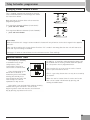
Installation
Ÿ Remove wallplate from unit by unscrewing the two
screws on the bottom edge of the unit.
Ÿ From the top left hand corner of the wallplate, there
must be clearances of at least 140 mm to the right,
15mm to the left, 30mm above and 100mm below
in order to mount the plug-on module.
Ÿ The wallplate must be securely mounted either
directly to the wall using suitable wood screws or to a
flush mounted 1-gang electrical accessory box using
M3.5 screws.
Ÿ Cable access can either be from behind for
concealed cabling, or from below for surface cabling.
If surface cable is used, cut out cable access slot on
plug-on module prior to mounting the module.
Ÿ For wiring connections refer to the diagrams.
Ÿ TS715-Si models are double insulated and do not
require an earth connection, however a parking
terminal is provided on the wallplate. This is clearly
marked with an Earth symbol.
Ÿ Prior to mounting the plug-on module, DIL switches on
the rear of the plug-on module must be set. See
diagram below for available options.
Ÿ Mount plug-on module to wallplate by locating tabs on
top of wallplate in apertures on rear of module, hinge
down and press firmly to wallplate before tightening
securing screws on bottom of wallplate. Before
mounting the unit, ensure the 4 DIL switches on the
rear have been moved to the required settings.
Wiring - See page 21 for further details
Please Note:
Always switch off mains first and never fit programmer to a live wallplate.
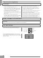
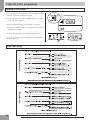
DIL Switch Settings
Before mounting the unit, ensure the 4 DIL switches on
the rear have been moved to the required settings.
Tick the INSTALLER SETTING box on the inside flap
label to notify user in which mode their unit is set (24hr,
5/2 day or 7 day).
44
Sw.1
Not Used
Not Used
Sw.2
Not Used
Not Used
Sw.3
5/2 Day
7 Day or 24 Hour
Sw.4
7 Day
24 Hour
INSTALLER SETTING
24Hour
5+2 Day
7 Day
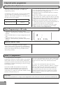
7 day hot water programmer
Advanced Programming Options
To enter advanced programming press PROG, + and DAY/HOL together and hold for 5 seconds.
Option 1 - (3 or 2 On/Off’s per day)
Use + or - to change between 3 and 2 on/off ’s each day.
Option 2 - (Disable or enable auto time change)
Option 2 - (Disable or enable auto time change)
Press NEXT, then use
+ or NEXT,
- change between
auto +
time
enabled
and auto time
Press
then use
orchange
- change
between
autochange
timedisabled
change
Option 8 - (Advanced Copy Functions)
Press NEXT, then + or - to change between the
following copy options:
(0) Standard copy in 7 day and 5+2 day.
(1)Enhanced copy in 7 day, standard copy in 5+2 day
(2)Enhanced copy in 7 day, AB copy in 5+2 day.
For an explanation of the copy features and how to use
them please see copy functions explained section
below.
Press PROG to return to RUN.
Copy Functions Explained
There are 3 possible copy functions available. These are;
Standard Copy, Enhanced Copy, and AB copy. Copy
functions are enabled/disabled in the Advanced
Programming Options (above).
Standard Copy: Pressing copy will copy the previous days
events into the displayed day. The unit will then display
the 1st event for the new day. This copy function is
present only if the unit is set to run in 5+2 or 7 day
mode.
Enhanced Copy: The enhanced copy function is available
in 7 day mode only. This allows any day to be copied to
any other day, or days. To use the enhanced copy
function go into the event programming using the PROG
button, then:
1. Use the DAY button to find the day to be copied from.
2. Press the COPY button to select the day to be copied
from.
When selected, the day should begin to flash.
3. Use the DAY button to find the day to be copied to.
4. Press COPY button to copy the selected day.
5. Repeat steps 3 and 4 to select and copy other days.
6. To stop copying, use the DAY button to go back to the
flashing day and press the COPY button. The previously
flashing day will stop flashing to indicate it has been
Please Note:
When a day has been copied to, it will remain visible and not flashing when the DAY button is used to select other
days.
45
7 day hot water programmer
Copy Functions Explained
AB Copy: The AB copy function is available in 5+2
mode only and only if activated in the Advanced
Programming setting.
A and B days, when selected, can be any group of days
e.g. 5+2, 4+3 etc. The days do not have to run in
sequence. For example, to operate in a 5+2 day mode
the days can be set as follows:
A Days
Mon Tues Thurs Fri Sat
B Days
Wed Sun
To use the AB copy function – press the PROG button:
1.This will show the “A” days, with all the days selected.
2.Use the DAY button to highlight a day.
3.Subsequent presses of the DAY button will increment
through the days.
4.Press the + button to select a specific day as an “A”
day, or press the – button to specify a day as a “B” day.
5.Once the day has been selected as an “A” or “B” day the
programme will automatically jump to the next day.
6.When the last day of the week is active, pressing +, -,
or DAY will move back to the “A” days displayed with no
selected (flashing) days (see image below).
7.Repeat 2 to 6 until all selections have been made.
8.When selections are completed, press the PROG
button to move to event programming.
Event Programming in AB mode
1.Programme “A” day events using the + (time
advance), - (time decrease), and NEXT (next period)
buttons.
2.Press the DAY button to change to programme the “B”
days
3.Programme “B” day events using the + (time
advance), - (time decrease), and NEXT (next period)
buttons.
Service Interval Timer
The TS715 Si is fitted with an installer setback
service interval timer. If this feature is required please
contact our technical department. Setting instructions
for this gas safety feature are only available to bona
fide heating installers.
What is a programmer?
... an explanation for householders.
Programmers allow you to set ‘On’ and ‘Off ’ time periods.
Some models switch the central heating and domestic
hot water on and off at the same time, while others allow
the domestic hot water and heating to come on and go
off at different times.
Set the ‘On’ and ‘Off’ time periods to suit your own
lifestyle. On some programmers you must also set
whether you want the heating and hot water to run
continuously, run under the chosen ‘On’ and ‘Off ’ heating
periods, or be permanently off.
The time on the programmer must be correct. Some types
have to be adjusted in spring and autumn at the changes
between Greenwich Mean Time and British Summer
Time.
You may be able to temporarily adjust the heating
programme, f o r example, ‘Override’, ‘Advance’ or ‘Boost’.
These are explained in the manufacturer’s instructions.
The heating will not work if the room thermostat has
switched the heating off. And, if you have a hot-water
cylinder, the water heating will not work if the cylinder
thermostat detects that the hot water has reached the
correct temperature.
Please Note:
Please note: A timeswitch is a single channel programmer. It will allow you to set your system’s On and Off periods.
46
7 day hot water programmer
Your timeswitch
The TS715-Si allows you to switch your system on and
off at times that suit you.
You can programme up to 3 separate ON/OFF times per
day.
Preset Programmes
Your TS715-Si comes ready programmed with a set
of operating times which often suit most people.
If you want to change any of these settings, you can do so
by following the instructions on pages 48-51. First, follow
the steps below and on page 48 to set the correct time
and date.
"Event No."
"Hot Water & Heating"
Mon-Fri
Sat-Sun**
1
1st ON
06:30
07:30
2
1st OFF
08:30
10:00
3*
2nd ON*
12:00*
12:00*
4*
2nd OFF*
12:00*
12:00*
5
3rd ON
17:00
17:00
6
3rd OFF
22:30
22:30
"* Not applicable if unit set to 2 ON/OFFs per day by installer
**Not applicable if unit set to 24 hour mode by installer
See page 48 for explanations of different settings"
Before you start
Open the flap on the front of the clock. Press the RESET
button using a non-metallic object (e.g.
Pencil/matchstick) until you hear a click and the red
light on the front of the unit comes on and the LCD goes
blank.
This will reinstate the preset programmes and sets
correct day and time.
DAY/HOL
To fully reset the unit see page 54.
Choice of 24hr or AM/PM display
Press and hold DAY/HOL & NEXT ON/ OFF for 2 seconds
to toggle between 24hr clock and AM/PM display, as
required.
DAY/HOL
47
7 day hot water programmer
Setting the correct Time and Day
These settings are made during manufacture and only
need to be made in the unlikely event that the unit has
lost the settings.
DAY/HOL
Setting the Date
Press and hold PROG for 5 seconds to display year.
Use the + or - buttons to set the correct year.
Press DAY/HOL to display day and month. Use the + or buttons to set the correct month (Jan = 1, Feb = 2 etc.).
Press DAY/HOL to display day and month. Use the + or buttons to set day of month.
Press PROG to display the time.
The words SET TIME will appear at the top of the display
& the time will flash on and off .
Use the + or - buttons to set the correct time (press and
hold to change in 10 min. increments).
Setting the Day
The day of the week is set automatically.
Accepting the preset programmes
If you are happy to use the preset programmes on page
47, you don’t need to do anything else.
To accept the factory presets just press the PROG button
once until the time appears and colon in the display
begins to flash.
Your unit is now in RUN mode and will control your
heating
Before you change the preset programmes
Your installer will have set your unit to operate in one of
the following modes:
• 5/2 day - one set of programmes for weekdays and
another for weekends (page 49)
• 7 day - different settings for each day of the week
(page 50)
• 24 hour - one set of programmes for the whole week
(page 51)
See INSTALLER SETTING tick box on inside
flap label to ascertain which mode your unit
is set.
Please Note
The unit must be programmed in sequence and ON/OFF times cannot be set out of sequence.
If you want to leave a preset time as it is, simply press NEXT to move on to the next setting.
Your installer will have set your unit to programme either 2 or 3 ON/OFFs per day. If your clock has been
installed to allow 3 ON/OFFs and you do not wish to use one of the ON/OFF settings, simply programme the
ON time to be the same as the OFF time and the setting will not operate.
48
7 day
programmer
7
dayhot
hotwater
water
programmer
Programming the ON/OFF Times in 5/2 day mode
1.Press PROG once until SET ON TIME appears at the
top of the display and MOTUWETHFR appears at the
bottom of the display.
Use the + or - buttons to set the time you would like your
system to first come on in the morning (Event 1).
2.Press NEXT ON/OFF once only.
Use the + or - buttons to set the time you want your
system to go off (Event 2). To move to the next setting,
i.e. when you would like your system to come on again
(Event 3) press the NEXT ON/ OFF button again.
3.Continue programming system ON and OFF times for
weekday Events 4, 5 & 6 as in Step 2.
4.Press the DAY/HOL button once and SASU will appear
at the bottom of the display.
5.To set the times required for SA and SU repeat steps 1
to 3 or if the same settings are required press COPY.
6.Press the PROG button once to return the unit to RUN
mode (time appears & colon in the display begins to
flash).
7.Proceed to bottom of page 51.
49
7 day hot water programmer
Programming the ON/OFF Times in 7 day mode
1.Press PROG once until SET ON TIME appears at the
top of the display. Note the current day is displayed.
Press the DAY/ HOL button until the required day is
displayed.
Use the + or - buttons to set the time you want your
system to first come on in the morning (Event 1).
2.Press NEXT ON/OFF to move to Event 2.
Continue programming the system ON and OFF times
in this way by using the + or - buttons to set the time
you want and pressing the NEXT ON/OFF button to
move to the next setting.
3.Press DAY/HOL button once only. The next day will
appear at the bottom of the display.
Continue programming the rest of the week by pressing:
a) NEXT ON/OFF button to move to the next setting,
b) + or - buttons to amend the time,
c) DAY/HOL to advance to the next day.
d) To copy the previous day press the COPY button.
4.Press the PROG button to return the unit to RUN
mode (time appears & colon in the display begins to
flash).
5.Proceed to bottom of page 51.
50
7 day hot water programmer
Programming the ON/OFF Times in 24 hour mode
1.Press PROG once until SET ON TIME appears at the
top of the display.
Use the + OR - buttons to set the time you want your
system to first come on in the morning (Event 1).
2.Press NEXT ON/OFF to move to Event 2.
Continue programming the system ON and OFF times
by pressing:
a) NEXT ON/OFF button to move to the next setting,
b) + or - buttons to amend the time,
3.Press the PROG button to return the unit to RUN
mode (time appears & colon in the display begins to
flash).
4.Proceed as below.
Running your Programme
To run the programme:
press the SELECT
Each time you press the SELEC
SELECT button the display will
change between ON, OFF,
ALLDAY and AUTO.
• AUTO = the system will come on and go off at the
programmed times.
• ON = the system will remain on constantly.
• OFF = the system will not come on.
• ALLDAY = the clock will turn the system on at the
first programmed ON and will leave it on until your
last programmed OFF.
Select the option you require depending on your
circumstances, time of year, etc.
51
7 day hot water programmer
Temporary override buttons
Sometimes you may need to change the way you use
your heating temporarily, i.e. due to unusually cold
weather. The TS715 Si has two convenient overrides
which can be selected without affecting the set
programme.
+1HR = pressing this button when the unit is in AUTO
or ALLDAY mode will cause the system to remain on for
an extra hour. If it is pressed while the unit is OFF, the
system will come on immediately for 1 hour then go off
again. +1HR will be shown in the display.
MAN = pressing this button when the unit is in AUTO or
ALLDAY mode will cause the system to go OFF until the
next programmed ON, or vice versa. MAN will be shown
in the display.
Holiday Programme
To automatically bring the heating back on when
returning from holiday the TS715 Si has a built in
holiday feature. Follow the steps below to set the date
that the heating system needs to come back on.
1.Press DAY/HOL
2.Use the + or - buttons to select the year.
3.Press DAY/HOL, then use the + and - buttons to select
the month.
4.Press DAY/HOL again, then use the + and - buttons to
select the day in month.
5.Press DAY/HOL to turn heating off and enter holiday
mode.
To cancel holiday mode press DAY/HOL.
52
7 day hot water programmer
Changing clocks forward & back
This is handled automatically. Should the installer
have turned off Automatic Time Change then follow
the instructions below.
Open the flap on the front of the unit to reveal the
programming buttons.
To change from Summer to Winter (clocks back) • press and hold - button
To change from Winter to Summer (clocks forward) • press and hold + button
Please Note
rst time this change has been
After the first time this change has been made this feature will only allow the clock to be changed in the opposite
direction.
Take care when making this change for the first time. If it is made in the wrong direction the unit will have to be
reset and any user-settings re-entered
(see pages 47 & 48 on how to Reset the unit and how to set the Time and Day).
Service Interval Timer
If the property is owned by
a landlord he may, for gas
safety reasons, have
instructed the installer to
set the service interval timer.
If set, 28 days prior to the
boiler service due date, a
momentary visual and audible
warning will remind you to
have the boiler serviced in the
next 28 days. This will be
repeated each day at noon.
• In addition, all overrides and programming buttons will
be disabled and the heating and hot water will operate
for a set portion of each programmed hour.
• The installer will cancel or reset the service interval
timer as part of the boiler service.
• This is a gas safety feature that can only be accessed by
an installer.
• When the service interval timer is set the service due
date can be viewed in RUN mode by pressing and
holding the COPY button.
If the boiler is not serviced within 28 days the daily
audible warning will sound for 1 minute at the
beginning of each hour and must be cancelled each
day by pressing any button on the unit.
53
7 day hot water programmer
Making a Full Reset
If it is necessary to fully reset the unit, including the date
and time, follow the instructions below.
1.Press and hold the +1HR and MAN buttons on the left
hand side of the product.
2.Press the RESET button and hold for 3 seconds.
3.Release the RESET button. The display will change to
show the current time
4.Finally, release both the +1HR and MAN buttons.
The unit is now fully reset and must be re-programmed,
see pages 47-49.
Example
No Heating
No Hot Water
Fault Check List
54
Programmable room stat
Installation & User Instructions
Index
Installation Instructions
Product Specification
Installation
Cable Access and Wiring
Installer Advanced Programming Options
User Instructions
What is a Programmable Room Thermostat
Preset programmes
Setting Date and Time
Changing Preset Programmes
User overrides
Advanced User Programming Options
Overview of Installer Selectable Features
Setting References
Please Note:
This product should only be installed by a qualified electrician or competent heating installer and should be in
accordance with the current edition of the IEEE wiring regulations.
Product specification
Thermostat features
Power supply
TP5000 Si
TP5000-RF Si
2 x AA/MN1500/LR alkaline cells
Memory back-up
TP5000M 24 Si
230V, ±15%, 50Hz
24V, ±15%, 50Hz
Retained for life of product
Temperature Range Sensing
5-30°C
Factory set calendar clock
Switching action of output relay
TP5000M Si
Automatic summer/winter time change
3(1)A, 10-230V
N/A
3(1)A, 10-230V, Type 1B
Transmission frequency (RF models)
N/A
433.92MHz
N/A
N/A
Transmission range (RF models)
N/A
30m max.
N/A
N/A
Remote sensor inputs (A models only)
Dimensions (mm)
Design standard
Can be set by installer for remote temperature sensor, limit sensor, window contact or
telephone activated switch contacts
110 wide, 88 high, 28 deep
EN60730-2-9 (EN300220 for RF)
Rated impulse voltage
2.5kV
Ball hardness test
75°C
Control pollution situation
Temperature accuracy
Time accuracy
Degree 2
±1°C
±1 minute per month
Important note RF products: Ensure that there are no large metal objects, such as boiler cases or other large
appliances, in line of sight between the transmitter and receiver as these will prevent communication between
thermostat and receiver.
55
Programmable room stat
Installation
• First, remove the wallplate from the back of the unit.
• From the top left hand corner of the wallplate, there
must be clearances of at least 15mm to the right,
15mm to the left, 30mm above and 100mm below in
order to mount the plug-in module.
• Thermostat and Remote Room Sensor: Fix at a height
of approximately 1.5m from the floor, away from
draughts or heat sources such as radiators, open fires
or direct sunlight.
• Prior to mounting the unit the 2 DIL switches on the
rear of the unit have to be moved to the required
position. The factory presets are shown opposite
Cable Access
Battery Installation
When installing the batteries in the TP5000 Si and
TP5000 Si RF please ensure that the correct polarity
is observed as per the markings on the inside of the
battery compartment.
IMPORTANT: After installing the batteries press and
release the RESET button to start the unit. The display
may appear blank until this is done. Once the button is
released the display will appear. All date, time,
programming and override settings are maintained for the
life of the product.
Wiring
Output Connections,
all hard wired models
Power Supply Connections
M 230V Models
N
L
D E
Remote
Sensor
M 24V
56
A
B
0V
24V
C
D E
Remote
Sensor
1
2
3
Programmable room stat
Please Note:
Some existing thermostats will have a Neutral and/or Earth wire connected. These are not required by the battery
powered versions of the TP5000 Si and must NOT be connected to any battery powered TP5000 Si terminals.
Instead they should be made electrically safe and coiled in the recess at the back of the TP5000 Si.
Models with remote sensor inputs
The TP5000A Si, TP5000A-RF Si and TP5000MA Si
incorporate an input which can be used to connect one of
the following:
/D
/E
1) remote room temperature sensor (sold as accessory).
2) limit sensor, for example, floor temperature sensor (sold
as accessory).
3) window contacts, card reader contacts or teleswitch
S1/ D
contacts.
S2/ E
Remote
control
connections
Battery powered
versions
S1/ D
S1/ D
S2/ E
S2/ E
See Installer Advanced Programming Options for set-up
instructions.
Window
cont act (NC)
Window or
t eleswit ch
cont act (NO
or NC)
Terminal block for remote control/ sensing is located on
the circuit board above the battery compartment.
Note:
Battery powered versions use S1 and S2.
Mains powered versions use D and E.
RX Receiver Wiring (RF models only)
Configured for
remote room
sensor or
limit
RX1
Teleswit ch
cont act (NC)
Configured for
window contact or
other contact such
as teleswitch
Configured for
window contact
and other contact
such as teleswitch
RX2& RX3
1) For mains voltage operated systems link terminal 2 to
mains live supply.
2) Power supply to unit must not be switched by
timeswitch.
IMPORTANT
To ensure that the factory programmes are set and the microcomputer is operating correctly it is essential that you
press and hold the RESET button before you begin any commissioning or programming.
Commissioning (RF models only)
If the thermostat and the receiver have been supplied
together in a combined pack, the units have been paired
in the factory and no commissioning is required (RX1
only). To make the RX receiver learn the thermostat’s
signal, follow steps 1-5.
Step 1:TP5000-RF Si - Reset the unit
by pressing the recessed reset button.
Step 2: Press and hold ˆ and +
buttons for 3 seconds (TP5000 RF Si
now transmits unique signal
continuously for 3 minutes).
RX1- Press and hold buttons PROG a n d CH 1 for
Step 4
RX2 (if applicable)
Stat 1 - perform steps 1-3 and 5.
Stat 2 -perform steps 1-2 and then press PROG and CH2
on RX2.
RX3 (if applicable)
Stat 1 - perform steps 1-3 and 5.
Stat 2 - perform steps 1-2 and then press PROG and CH2
on RX3 then step 5.
Stat 3 - perform steps 1-2 and then press PROG and CH3
on RX3.
Step 5: TP5000Si-RF - Press ‡ or ˆ to select
temperature - the unit will revert back to operating mode.
Step 3: RX1 - Press and hold buttons
PROG and CH1 for 3 seconds until
green light flashes once.
57
Programable room stat
Installer advanced programming options
TP5000 Si incorporates a number of advanced features
which can be set by the user. These are accessed via a
User Advanced Programming Mode, please refer to User
Advanced Programming in the user instructions for
details (see page 67).
Installer advanced programming options
TP5000 Si incorporates an additional number of
advanced features which can be set by the installer to
improve the operating efficiency of the system and
where required, to change the user functionality of the
product. These are accessed via an Installer Advanced
Programming Mode.
These settings are optional and need only be made if there
is a demand for the enhanced functions.
Entering Installer Advanced Programming Mode
To access the Installer Advanced
Programming Mode follow the steps below:
a) Press and hold ˆ and PROG for 3
seconds to enter User Advanced
Programming, the display will change
to figure opposite.
b) Press and hold ‡ , ˆ and PROG for
5 seconds to enter Installer Advanced
Programming, the display will change
c) Use + and - keys to scroll backwards and forwards between
to figure opposite.
c) Use + and - keys to scroll backwards and forwards
between options then ‡ and ˆ keys to change the
option settings. The flashing digit on the right hand of
the display indicates the number of the selected option.
The large characters display the option value selected.
d) To return to RUN, press
Option 30 - Set upper limit of temperature range
Option 31 - Set lower limit of temperature range
This allows the upper limit of the
thermostat setting range to be electronically limited. Press + until Option
30 is displayed, use ‡ & ˆ to select
required setting.
This allows the lower limit of the
thermostat setting range to be electronically limited. Press + until Option
31is displayed, use ‡ & ˆ to select
required setting.
Setting
Setting
40 - 5°C (Factory setting is 30°C)
5 - 40°C (Factory setting is 5°C)
Option 32 - Enable Off at lower limit
Option 33 - Enable On at upper limit
This enables an OFF function to be
selected if a set point below the lower
limit is selected. Press + until Option
32is displayed, use ‡ & ˆ to select
required setting.
This enables an ON function to be
selected if a set point above the upper
limit is selected. Press + until
Option 33 is displayed, use ‡ & ˆ to
select required setting.
Setting 0
Disabled
Setting 0
Disabled (factory setting)
Setting 1
Enabled (factory setting)
Setting 1
Enabled
58
Programmable room stat
Option 34 - Select On/Off Chrono-proportional
This allows the thermostat to be set to
This allows the thermostat to be set to run in
run in On/Off mode or for a chronoproportional cycle rate to be selected.
Press + until Option 34 is displayed,
use ‡ & ˆ to select required setting.
Option 35 - Set integration time (Option 34 set to 3, 6, 9
or 12) (seek advice prior to adjusting)
0
On/Off
3
3 cycles per hour
6
6 cycles per hour (factory setting)
This adjusts the integration time of
the PI algorithm to increase control
accuracy. It is only active if option 34
has been set to Chrono 3, 6, 9 or 12.
It should only be adjusted after seeking
advice from the manufacturer. Press +
until Option 35 is displayed, use
‡ & ˆ to select required setting.
9
9 cycles per hour
2.5
Integration time set to 2.5% (factory setting)
12
12 cycles per hour
5
Integration time set to 5%
10
Integration time set to 10%
Option 36 - Set temperature override rule
This establishes the degree of temperature override available to the user.
Press+ until Option 36 is displayed,
use ‡ & ˆ to select required setting,
Option 37 - Set time duration of override rule
(Option 36 set to 1 or 2)
Setting 0
No limit (factory setting)
This establishes the duration of a temperature override available to the user.
Press + until Option 37 is displayed,
Use ‡ & ˆ to select required setting.
Setting 1
Limited to ±2°C
Setting 0
Next event (factory setting)
No override allowed
Setting 1
1 hour
Setting 2
2 hours
Setting 3
3 hours
Setting 4
4 hours
Setting 2
Option 38 - Relay state on low battery detect
(battery products only)
This establishes the position that the
relay is driven to when the unit shuts
down due to low battery state.
Press + until Option 38 is displayed,
use ‡ & ˆ to select required setting.
Option 40 - Number of Events per Day
This sets the thermostat to operate
with either 2, 4 or 6 switching events
per day or to run it in stat mode.
Press + until option 40 is displayed,
use ‡ & ˆ to select required setting.
1
Stat mode
Setting 0
Relay parked with output OFF (factory setting)
2
Two switching events per day
Setting 1
Relay parked with output ON
4
Four switching events per day (Factory setting)
6
Six switching events per day
Setting 4 4 hours
Option 41 - Operating Mode (5/2 day or 24 hour)
Option 70 - Keyboard disable rules
This sets the thermostat to operate
using either 5/2 day or 24 hour mode.
Press + until option 41 is displayed,
use ‡ & ˆ to select required setting.
This establishes the degree of
functionality of the
keyboard available to the user.
It is only active if DIL
switch 1 is set to “Disabled”.
Press + until Option 70 is
displayed, use ‡ & ˆ to
select required setting.
5-2
5/2 day (Factory setting)
24
24 hour
Setting 0 Normal lock: Programming functions locked
(factory setting)
Setting 1 Full lock: All keys are disabled
59
Programmable room stat
Option 71 - Random start rules (24V/230 Volt models only)
Option 72 - Owner site reference number
This enables a random start on power-up following a power cut to reduce
load on the electrical network.
Random delay is in the range of 2-90
seconds. Press + until Option 71 is
displayed, use ‡ & ˆ to select
required setting.
This enables multi-site owners
to store a site reference
number in the thermostat.
Press + until Option 72 is
displayed, use ‡ & ˆ to
select required setting.
Setting 0
Disabled (factory setting)
Factory setting is 00
Setting 1
Enabled
Setting
Any value between 00 and 99 can be set
Option 73 - Owner thermostat reference number
Option 74 - Date format for calendar clock
This enables site owners to store a
thermostat reference number in the
thermostat. Press + until Option 73
is displayed, use ‡ & ˆ to select
required setting.
This allows date format to be
chosen. Press + until Option
74is displayed, use ‡ & ˆ to
select required setting.
Setting
Setting 1 North American format (mm/dd/yy)
Any value between 000 and 999 can be set
Setting 0 European format (dd/mm/yy), (Factory setting)
Factory setting is 000
Option 81 - Thermostat calibration bias
Option 90 - Define remote sensor type, “A” models only
This allows the thermostat calibration
to be biased by up to ±1.5°C. Press
+ until Option 81 is displayed, use
‡ & ˆ to select required setting.
This allows type of remote
sensor input type to be defi
ned. Press + until Option 90
is displayed, use ‡ & ˆ to
select required setting.
Setting
Any value between ±1.5 in 0.5°C steps
(Factory setting is 0°C)
Setting 0
No remote sensor fitted (Factory setting)
Setting 1
Remote room or duct sensor fitted, internal sensor disabled,
Setting 2
Remote limit sensor fitted, refer to option 93 to
define set-point
Setting 3
Configured as digital input for window, card
reader or teleswitch, refer to option 94 to define
o/c or s/c.
Setting 4
4 hours
Option 93 - Set limit sensor set-point, “A” models only,
(option 90 set to 2)
Option 94 - Configure digital input switch type, “A” models
only, (option 90 set to 3)
This allows the thermostat limit sensor to be set, typical application is fl
oor heating. Press + until Option 93 is
displayed, use ‡ & ˆ to select
required setting. If the temperature
sensed by the limit sensor exceeds
the limit setting the output will be
turned off until the temperature
has dropped by 2°C. “F10” will flash
in the display while the output is
disabled.
This allows switch type of
digital input to be configured.
Press + until Option 94 is displayed, use ‡ & ˆ to select
required setting.
Setting
60
Any value between 20 - 50°C (Factory setting
is 27°C)
Setting 0 Contacts NC, open circuit contact to force unit
into thermostat mode, short circuit contacts to
return to normal operation
Setting 1 Contacts NO, short circuit contacts to force unit
into thermostat mode, open circuit contacts to
return to normal operation (Factory setting)
Programmable room stat
What is a programmable room thermostat?
... an explanation for householders
A programmable room thermostat is both a programmer
and a room thermostat. A programmer allows you to set ‘On’
and ‘Off’ time periods to suit your own lifestyle. A room
thermostat works by sensing the air temperature, switching
on the heating when the air temperature falls below the
thermostat setting, and switching it off once this set
temperature has been reached.
The best way to do this is to set low temperatures first,
say 18°C, and then turn them up by one degree each
day until you are comfortable with the temperatures.
You won’t have to adjust the thermostat further. Any
adjustments above these settings will waste energy and
cost you more money.
If your heating system is a boiler with radiators, there
will usually be only one programmable room thermostat
to control the whole house. But you can have different
temperatures in individual rooms by installing
thermostatic radiator valves (TRVs) on individual
radiators.
So, a programmable room thermostat lets you choose what
times you want the heating to be on, and what temperature
it should reach while it is on. It will allow you to select
different temperatures in your home at different times of
If you don’t have TRVs, you should choose a
the day (and days of the week) to meet your particular
temperature that is reasonable for the whole house. If
needs.
you do have TRVs, you can choose a slightly higher
Turning a programmable room thermostat to a higher
setting to make sure that even the coldest room is
setting will not make the room eat up any faster. How
comfortable, then prevent any overheating in other
quickly the room heats up depends on the design of the
rooms by adjusting the TRVs. The time on the
heating system, for example, the size of boiler and
programmer must be correct. Some types have to be
radiators.
adjusted in spring and autumn at the changes between
Greenwich Mean Time and British Summer Time.
Neither does the setting affect how quickly the room cools
down. Turning a programmable room thermostat to a lower
You may be able to temporarily adjust the heating
setting will result in the room being controlled at a lower
programme, f o r example, ‘Override’, ‘Advance’ or
temperature, and saves energy.
‘Boost’. These are explained in the manufacturer’s
instructions. Programmable room thermostats need a
The way to set and use your programmable room
free flow of air to sense the temperature, so they must
thermostat is to find the lowest temperature settings that
not be covered by curtains or blocked by furniture.
you are comfortable with at the different times you have
Nearby electric fires, televisions, wall or table lamps
chosen, and then leave it alone to do its job.
may prevent the thermostat from working properly.
An introduction to your programmable room thermostat?
Your programmable room thermostat allows you to
programme different temperatures at different time
periods. You can programme one set of times and
temperatures for week days with a different set of
temperatures for weekend days, this is referred to as 5/2
day operation.
The thermostat can also be set up by your installer to
provide one set of times and temperatures that are
repeated each day of the week. This is referred to as 24
hour operation. The thermostat can also be set by you to
provide two different programming blocks which can then
be assigned to any day of the week, this is referred to as
A/B programme operation.
All thermostats can be set by your installer to provide up
2, 4 or 6 time and temperature settings each day. All
thermostats feature useful overrides, including a
programmable frost setting.
Your thermostat has some advanced features which the
installer will set-up if they are required. There are also a
number of advanced features which can be set up by you.
These advanced settings alter the way that your
thermostat operates, some also affect the programming
functions and the user overrides. Please read the User
Advanced Programming instructions before programming
the unit (see page 67).
Preset programmes
Your TP5000 Si comes ready programmed with a set of
operating times and temperatures which suit most
people. Please remember that some of the options
available will depend on how the installer has set up the
unit.
61
Programmable room stat
Event
1
2
3
4
5
6
Weekdays (Mon-Fri)
Time
Temp. °C
06:30
20
08:30
15
11:30
20
13:30
15
16:30
21
22:30
18
Weekend (Sat-Sun)
Time
Temp. °C
07:30
20
09:30
20
11:30
20
13:30
20
16:30
21
22:30
18
Event
1
2
3
4
5
6
Note: these are also times for
Block “A” programmes
Note: these are also times for
Block “B” programmes
Note: If set up for 4 events per day, events 3 & 4 are skipped. If set up for
2 events per day, events 2, 3, 4 & 5 are skipped. In both cases the events are re-numbered.
Before you start
Open the flap on the front of the programmer and
press the RESET button with a non-metallic object
until the display goes blank. This will ensure that the
micro-computer in the product is operating correctly.
RESET
Customising the display
For the sake of clarity, the instructions assume that the
display setting uses a 24 hour clock, °C and that days of
the week are shown as text.
All of these settings can be personalised after the
thermostat has been programmed, see pages 65-66
Setting the correct date and time
Your TP5000 Si incorporates a real time clock with
calendar function that automatically changes time in
both Spring and Autumn. The time and date is set in
the factory for the UK time zone, and does not normally
require adjustment.
If you live in another time zone refer to “Time zone off
set” on page 67. However, should it be found necessary
to adjust time or date for any other reason refer to the
following instructions.
Setting the date
Press and hold ‡ and PROG for 3 seconds, to display
PROG for 3 seconds, to
date in dd/mm/yy format.
The YEAR number will flash, use ‡ or ˆ to correct the
year.
Use - or + to move to MONTH, then use ‡ or ˆ to
correct month.
Use - or + to move to DATE in month, then use ‡ or ˆ
to correct day in month.
If you attempt to select an invalid date the unit software
will reject it and apply the nearest valid date. It is
recommended that date is set in the order, yy/mm/dd.
62
Programmable room stat
Setting the correct time
After setting the date press PROG to display the time.
The time display will flash on and off.
Use the + and - buttons to set the correct time (press
and hold to change in 10 min. increments).
Setting the correct day
The day of the week is set automatically. Press
PROG to return to normal operation (RUN).
Accepting the preset programmes
If you are happy with the preset times shown in the table
on page 62 you need take no further action.
Changing the preset programmes
Before you change the preset programmes Your installer
will have set the unit to operate in one of the following
modes:
• 5/2 day - one set of programmes for weekdays and
another for weekends as per section below
• 24 hr - one set of programmes for the whole of the week
(page 64).
Alternatively
• A/B - The unit can also be set by you to provide two
programme blocks, either of which can be applied to
different days of the week.
If this is required refer to page 64 for instructions on
how to turn on this feature.
Please Note
The unit must be programmed in sequence, event times cannot be set out of sequence.
If you want to leave a preset time as it is, simply press PROG to move to the next setting.
If you want to return the unit to RUN, press PROG and hold until the display returns to the previous RUN mode.
Alternatively leave alone and the unit will automatically return to RUN after 2 minutes.
Your installer will have set your unit to programme 6, 4 or 2 events per day. This will determine the number of
events per day that you are able to programme.
Changing the preset programmes in 5/2 day mode
For Weekdays
a) Press PROG until the first preset time and temperature
(Event 1 Days MON, TUE, WED, THU, FRI) appears in
display.
b) Use the + and - buttons to adjust the TIME (press and
hold to change in 10 minute increments).
c) Use the ‡ & ˆ buttons to adjust the required
TEMPERATURE.
d) Press PROG to move to the next preset time
and temperature (Event 2).
e) Repeat steps b, c, & d to programme the
remaining weekday events.
63
Programmable room stat
Changing the preset programmes in 5/2 day mode
For Weekends
Press PROG until the first preset time and
temperature (Event 1 Days SAT, SUN) appears in
display.
Repeat steps b, c, & d above to programme the
remaining weekend events.
Changing the preset programmes in 24 hour mode
a) Press PROG until the first preset time and temperature
(Event 1 for all days of the week) appears in display.
b) Use the + and - buttons to adjust the TIME (press and
hold to change in 10 min increments).
TIME (press and hold
c) Use the ‡ & ˆ buttons to adjust the required
c) Use the and V buttons to adjust the required TEMPERATU
TEMPERATURE.
d) Press PROG to move to the next preset time and
temperature (Event 2).
e) Repeat steps b, c, & d to programme the remaining
events.
Changing preset programmes for AB programming
(Installer setting must be in 5/2 day mode)
Press and hold PROG and V for 3 seconds. The display will
change to the figure opposite. This will take you into User
Advanced Programming option 1.
Use ‡ & ˆ keys to enable or disable the function
(1=enabled, 0=disabled).
Press PROG for 5 seconds until the display returns
to previous RUN mode.
Press PROG once, the display will change to show
the default days assigned to programme “A” (days
MON, TUE, WED, THU, FRI).
Use the + and - keys to scroll forwards or backwards
through the days of the week.
To deselect a day press V, (for example TUE). To
select a day press (for example SUN).
Any deselected days are automatically assigned to
programme “B”.
64
(Installer setting must be in 5/2 day mode)
Programmable room stat
Setting the correct time
a) Press PROG until the first preset
time and temperature (Event 1 for
Programme A) appears in display.
d) Press PROG to move to the next preset time and
temperature (Event 2).
b) Use the + and - buttons to adjust the TIME (press and
hold to change in 10 minute increments).
e) Repeat steps b, c, & d to programme the
remaining events
c) Use the ‡ & ˆ buttons to adjust the required
TEMPERATURE.
Programming “B” programme days and events
a) Press PROG until the first preset
time and temperature (Event 1 for
Programme B) appears in the display.
b) Use the + and - buttons to adjust the TIME (press and
hold to change in 10 minute increments).
d) Press PROG to move to the next preset time and
temperature (Event 2).
e) Repeat steps b, c, & d to programme the
remaining events.
c) Use the ‡ & ˆ buttons to adjust the required
TEMPERATURE.
Running the programme
Press PROG to return to previous RUN mode. The
heating will now follow the times and temperatures
programmed.
User Overrides
Altering the display to show time or temperature
Press + and - together to change between settings.
Temporarily alter current programmed temperature
Press ‡ & ˆ until required temperature is displayed.
Please note that your installer may have restricted both
upper and lower temperature settings and the temperature
override limits. This override will automatically be
cancelled at the beginning of the next programmed event.
Please note that your installer may have restricted the
duration of the override to something other than next
event.
In this case the override arrow will flash to indicate a
timed override is active during the next event
To change day of week legends from numbers to text
Press ‡ and - together to toggle between day numbers
and text.
65
Programmable room stat
To change time display between 12 hour and 24
Press ‡ and + together to toggle between 12 and 24
hour
To change between °C and °F scaling
Press ˆ and - together to toggle between °C and ° F
temperature scaling.
Thermostat mode
a) A constant temperature of between 5-30°C can be
selected if required. This can provide frost protection
for periods away from home, it can also be used to
provide untimed higher temperatures if, for
example, a family member is sick.
b) Press ‡ & ˆ together to enter thermostat mode.
The default setting is 5°C, but this can be
reprogrammed, see User Advanced Programming,
step 10, (page 67).
d) Use the ‡ & ˆ buttons to change the temperature
away from the programmed frost protection
temperature to another value.
e) To return to automatic programming press both ‡ &
ˆ together
c) A frost protection symbol (snowflake in
a shield) will appear in the display
when the selected temperature is
equal to or less than the programmed
frost protection setting.
Changing the clock forwards and backwards
This is handled automatically, however, if the manual
changeover has been selected (User Advanced
Programming step 3 on page 67) follow the instructions
below.
To change from Winter to summer (clocks forward)
With clock display showing, press and hold + button
until time moves forward.
To change from Summer to Winter (clocks back) With
clock display showing, press and hold - button until time
moves back.
Remote override into and out of thermostat mode
Selected models are available with a feature which allows
a telephone activated switch or window contacts to step
the unit into or out of thermostat mode.
The required temperature to be maintained when the
building is unoccupied, or when windows are open,
must first be set up in User Advanced Programming,
step 10, (page 67). To locally override this feature
press both ‡ & ˆ together.
Delay start feature
Your thermostat includes an optional delay start feature
to hold off the heating for a time on mild days when the
room temperature at the start of an event is close to the
programmed value. If you have enabled this function it
can be overridden by pressing either ‡ or ˆ buttons.
66
To enable this feature, please refer to User Advanced
Programming, step 11, (page 68).
When this function is active, the set temperature will
flash on the display and an hourglass symbol will be
displayed.
Programmable room stat
Optimum start control (OSC)
Your thermostat includes an optional optimum start
control. This feature allows you to set the time at which
you require a room temperature by.
A full description of this and how to enable it and
set it up is given in User Advanced Programming,
steps 12 & 13, (page 68).
The thermostat then calculates how soon before the event
time the system must be turned up to ensure that the
room is at the temperature by the required time.
When this function is active, the set temperature
will flash on the display
Battery replacement (battery models only)
When batteries are low a
battery symbol will appear on
the display. You have 15 days
to replace the batteries before
the unit shuts down. When
replacing batteries ensure that
IMPORTANT: After replacing the batteries press and
release the RESET button to restart the unit. All date,
time, programming and override settings are
maintained for the life of the product.
User Advanced Programming Options
Important: The thermostat has been set in the factory to suit most situations, however, there are additional
optional settings which can improve the comfort, convenience and energy effectiveness of your thermostat.
These are set in the User Advanced Programming and Installer Advanced Programming modes.
To access User Advanced Programming
Press and hold ˆ and PROG for 3 seconds. This will take The flashing digit on the right hand of the display
you into User Advanced Programming. Use + and - keys to indicates the number of the selected option.
scroll backwards and forwards between options then ‡ &
ˆ keys to change option settings.
Option 1 - Enable or disable A/B programming
(option 41 set to 5+2)
This enables or disables the A/B
programming option. Press + until
Option 1 is displayed, use ‡ & ˆ to
select required setting.
Setting 0
Setting 1
Disabled, unit operates as 5+2 or 24
hour product depending on installer
settings (factory setting)
Option 3 - Calendar clock rules
This establishes the rules that the
automatic calendar clock follows to
calculate changes between summer
and winter time. Press + until Option
3 is displayed, use ‡ & ˆ to select
required setting
Setting 0
Disabled.
Setting 1
Manual: user must change using + to
advance and -retard displayed time.
Setting 2
European rules. (Factory Setting)
Setting 3
USA rules (2007 onwards)
Setting 4
USA rules (pre-2007)
Enabled: activates A/B programming
Option 4 - Time zone offset
Option 10 - Frost/ thermostat mode setting
This feature allows the time zone to be
established and corrects time display.
Press + until Option 4 is displayed,
use‡ & ˆ to select required setting
This feature allows the default frost/
thermostat mode temperature to be set.
Press + until Option 10 is displayed,
use ‡ & ˆ to select required setting.
Setting 0
UK models: this feature should be left
at the factory setting of 0.
5-40°C - Factory setting is 5°C, but can be changed to any
value between 5-40°C.
Setting 1
Central European time models: this
feature should be left at the factory
setting of +1:00.
-12 Hours +14 Hours. Rest of World: use ‡ & ˆ keys to
select offset from Universal time (GMT) for the location in
which the thermostat is being installed.
67
Programmable room stat
Option 11 - Start-up method
Your thermostat can start up the
system in three different ways.
Press + until Option 11 is
displayed, use ‡ & ˆ to select
required setting.
Setting 0
Setting 1
Normal: Heating is turned up or down at the
programmed times.
Optimum start control (OSC) (or Comfort Setting): This allows you to programme the time at
which you would like to be up to the required
temperature. The thermostat then calculates
how soon before the required time the heating
is turned up. This will vary with weather
conditions ranging from a maximum of 120
minutes to 0 minutes before the programmed
event time. This setting must be used together
with option 12 to match the optimiser setting
to the building in which it is installed.
Setting 2
Delay start (or Economy Setting): This is an
alternative to OSC. Set the event times in the
normal way taking into account the time that
the building takes to heat on an average day.
The thermostat monitors switch on time,
actual temperature and wanted temperature
and delays the start of the heating if the actual
temperature is close to the programmed temperature.
Option 13 - Optimum start control/Delayed start event
setting (Option 11 set to 1 or 2)
The Optimum start or delayed
start control can be applied to
event 1 only or to each event of
the day which requires a higher
temperature than the previous
event. Press + until Option 13 is
displayed, use ‡ & ˆ to select
required setting (only active if
Option 11 is set to 1 or 2).
Setting 0
Setting 1
68
Applies only to first event of day. (Factory
setting)
Applies to each event of the day that requires
a higher temperature compared to previous
event.
Option 12 - Optimum start control pre-heat setting
(Option 11 set to 1)
Press + until Option 12 is displayed,
use ‡ & ˆ to select required
setting (only active if Option 11
is set to 1).
The optimum start control must be adjusted to match the
building energy characteristics. Use the ‡ & ˆ keys to
selected the required pre-heat period. The table below
suggests typical settings. If the building fails to reach
temperature on time, increase the setting by 15 minute steps
each day until the correct setting is found. If the building
reaches temperature ahead of time, decrease the setting by
15 minute steps each day until the correct setting is found.
00:15
15mins, warm air systems, well insulated building.
00:30
30mins, warm air systems, well insulated building.
00:45
45mins, warm air system poorly insulated building.
01:00
60 mins, radiator system, light weight well
insulated building. (Factory setting)
01:15
75 mins, radiator system, light weight medium
insulation.
01:30
90 mins, radiator system, medium weight poorly
insulation.
01:45
105 mins, radiator system, heavy weight building,
well insulated.
02:00
120 mins, radiator system, heavy weight building,
poorly insulated.
Programmable room stat
Temperature range limitation
This allows the installer to programme both upper and
lower temperature limits. It may limit the upper and lower
temperature that you are able to set on the thermostat.
Temperature override limitation
This allows the installer to limit the number of degrees
that you can override the programmed temperature by,
it also allows the installer to set rules regarding how
long a temperature override will remain in place.
Keyboard lock
This allows the installer to limit or lock the keyboard to
prevent unauthorised changes to programme values
and limits overrides.
What happens to the unit when batteries fail
If batteries are not changed within 15 days of a low
battery warning, the unit shuts down. In normal
circumstances the thermostat turns off the valve or the
boiler it is controlling. In extreme climates turning off the
heating is likely to result in the building freezing up. To
prevent this, the installer can set up the unit to turn the
heating ON rather than turn OFF on battery failure. This
will consume more fuel but will prevent damage occurring
to the building. If appropriate please check that the
installer has set this function correctly.
Please note: If you replace the batteries and the LCD
does not come on immediately please check battery
orientation. Do not leave batteries in the product if
the display is not active.
If, after changing the batteries, the screen remains
blank it is necessary to carry out a partial reset. See
below for details.
Service Interval Timer
• If the property is owned by a
landlord he may, for gas safety
reasons, have instructed the
installer to set the service interval
timer.
• If set, 28 days prior to the service
due date, a visual and audible
warning will start each day at
noon. The audible warning will
last for 10 seconds and will be
repeated every hour until a button
Service Interval
is pressed to cancel it. If cancelled
the alarm will recommence the
following day at noon.
• If the boiler is not serviced before the due date, a
visual and audible warning will start each day at
noon. The audible warning will last for 1 minute and
will be repeated every hour until a button is pressed
to cancel it. If cancelled the alarm will recommence
the following day at noon.
• In addition, all overrides and programming buttons
will be disabled and the heating may operate for a
limited amount of time each hour.
• The installer may cancel or reset the service interval
timer as part of the boiler service.
• This is a gas safety feature that can only be
accessed by an installer.
Resetting the unit
Partial reset: Press RESET (used to restart microcomputer) if display freezes for any reason. This does
not reset any programme, clock or date. It is
recommended that this is done at time of installation.
User full reset: Press RESET whilst holding down PROG
button. This resets event times and any User Advanced
Programme setting, but does not reset time or date.
Installer full reset: This is only available to the
installer. In addition to the above all of the Installer
Advanced Programming settings are returned to
factory settings, however, time, date and service due
date are not reset.
69
Programmable room stat
Settings Reference
Note to installers:
Please use this table to record changes to default settings.
Installer Settings
Option
Description
30
Set upper limit of temperature range
31
Set lower limit of temperature range
32
Enable Off at lower limit
33
Enable On at upper limit
34
Select On/Off or Chrono-proportional
35
Set Integration Time
36
Set temperature override rule
37
Set time duration of override rule
38
Relay state on low battery detect (battery products only)
40
Number of events per day
41
Operating mode (5/2 day or 24 hour)
70
Keyboard disable rules
71
Random start rules (24V/230V only)
72
Owner site reference number
73
Owner thermostat reference number
74
Date format for calendar clock
81
Thermostat calibration bias
90
Define remote sensor type (“A” models only)
93
Set limit sensor set-point (“A” models only)
94
Configure digital input switch (“A” models only)
Installer Set Value
User Settings
Option
Description
1
Enable or disable A/B programming
3
Calendar Clock Rules
4
Time zone off set
10
Frost/Thermostat mode setting
11
Start-up method
12
Optimum start control pre-heat setting
13
Optimum start control/Delayed start event setting
70
Installer Set Value
Spare Part List
KHP0041 - 4kW, KHP0038 - 6kW, KHP0039 - 8kW
71
Spare Part List
Pos.
Description
1
Base pan assy
1
2
Front panel
1
3
Ass. front side panel
1
4
Ass. rear side panel
1
5
Front service cover
1
6
Pillar
1
7
Ass. top cover
1
8
Fan guard grille
1
9
Fan motor
1
10
Motor nut
1
11
Propeller fan
1
12
Orifice
1
13
Handle
1
14
Condenser coil assy
1
15
Coil guard net
1
16
Compressor (DA111A1F-20F1)
1
17
Klixon
1
18
Klixon holder
1
19
Cushion rubber
3
20
Suction accumulator
1
21
Liquid receiver
1
22
/4 way valve
1
24
PMV liquid assy
1
25
PMV solenoid coil
1
26
outlet water pipe
1
27
Inlet water pipe
1
28
Ass. control box inverter
1
29
Reactor (CH-57-Z-T)
2
30
Drain pipe
1
31
-
-
32
Assembly control box GMC
1
33
GMC board
1
34
Brazed plate heat exchanger assembly
1
35
-
-
36
Water sensor
2
37
Flow switch
1
38
Automatic purge valve
1
39
Water pressure relief valve
1
701
Sensor (TD)
1
702
Sensor (TE)
1
703
Sensor (TS)
1
704
Sensor (TO)
1
705
Base. P.C. Board
1
706
Terminal block 6P, 20A
1
72
Qty
Note
Spare Part List
KHP0040 - 12kW, KHP0042 - 15kW
73
Spare Part List
Pos.
Description
Qty
1
Base pan assy
1
2
Front panel
1
3
Ass. front side panel
1
4
Ass. rear side panel
1
5
Front service cover
1
6
Pillar
1
7
Ass. top cover
1
8
Fan guard grille
2
9
Fan motor
2
10
Motor nut
2
11
Propeller fan
2
12
Orifice
2
13
Handle
2
14
Condenser coil assy
1
15
Coil guard net
1
16
Compressor (DA420A3F-21M)
1
17
Klixon
1
18
Klixon holder
1
19
Cushion rubber
3
20
Suction accumulator
1
21
Liquid receiver
1
22
4 way valve
1
24
PMV liquid assy
1
25
PMV solenoid coil
1
26
/inlet water pipe
1
27
/Inlet water pipe
1
28
Ass. control box inverter
1
29
Reactor (CH-57-Z-T)
2
30
Drain pipe
1
31
-
-
32
Assembly control box GMC
1
33
GMC board
1
34
Brazed plate heat exchanger assembly
1
35
-
-
36
/Water sensor
1
37
Flow switch
1
38
/Automatic purge valve
1
39
Water pressure relief valve
1
701
Sensor (TD)
1
702
Sensor (TE)
1
703
Sensor (TS)
1
704
Sensor (TO)
1
706
Terminal block 3P, 20A
1
707
Terminal block 3P, 30A
1
708
Rectifier
1
709
PCB
1
710
PCB
1
74
Note
Rating Tables
COP
115% 105% 100% 90% 80%
70% 60% 50% 40% 30% 15%
Hz
1.86 1.87 1.87
CAPACITY
115% 105% 100% 90% 80%
4 kW
Unit
-20
-10 2.33
2.41
2.44
2.46 2.5
2.53 2.56 2.59 2.60 2.61 2.61
EWTLWT
30-35
-7
2.53
2.62
2.65
2.67 2.71
2.75 2.78 2.81 2.83 2.84 2.84
-5
2.67
2.76
2.79
2.82 2.85
2.89 2.93 2.96 2.97 2.98 2.99
-5
-3
2.80
2.90
2.93
2.95 3.00
3.03 3.08 3.11 3.12 3.13 3.13
0
3.00
3.10
3.14
3.16 3.21
2
3.10
3.21
3.24
7
3.97
4.03
10
4.38
20
30
2.64
2.62
2.49 2.26
1.97 1.67 1.37 1.08 0.78 0.49
2.83
2.82
2.67 2.43
2.12 1.80 1.48 1.16 0.84 0.52
3.00
2.96
2.95
2.80 2.54
2.21 1.88 1.54 1.21 0.88 0.55
-3
3.13
3.09
3.07
2.91 2.65
2.31 1.96 1.61 1.26 0.92 0.57
3.25 3.30 3.33 3.35 3.36 3.36
0
3.33
3.28
3.27
3.10 2.82
2.45 2.08 1.71 1.34 0.97 0.61
3.27 3.32
3.36 3.41 3.44 3.46 3.47 3.47
2
3.50
3.45
3.44
3.11 2.97
2.58 2.19 1.80 1.41 1.02 0.64
4.05
4.09 4.14
4.2
7
4.73
4.61
4.10
3.77 3.39
2.94 2.51 2.05 1.61 1.20 0.77
4.45
4.47
4.51 4.57
4.63 4.68 4.71 4.73 4.74 4.74
10
5.14
5.01
4.45
4.09 3.68
3.20 2.72 2.23 1.74 1.30 0.83
5.73
5.83
5.85
5.92 5.99
6.06 6.13 6.17 6.20 6.22 6.22
20
6.49
6.33
5.62
5.17 4.65
4.04 3.44 2.81 2.20 1.64 1.05
7.09
7.21
7.24
7.32 7.40
7.50 7.58 7.63 7.67 7.69 7.69
30
7.85
7.65
6.79
6.25 5.62
4.88 4.16 3.40 2.66 1.99 1.27
115% 105% 100% 90% 80%
70% 60% 50% 40% 30% 15%
4.24 4.27 4.29 4.30 4.30
OAT
115% 105% 100% 90% 80%
70% 60% 50% 40% 30% 15%
Hz
1.81 1.82 1.82
CAPACITY
4 kW
Unit
-20
-10 2.07
2.11
2.11
2.13 2.16
2.19 2.21 2.23 2.24 2.25 2.25
EWTLWT
40-45
-7
2.19
2.23
2.24
2.26 2.29
2.32 2.34 2.36 2.37 2.37 2.38
-5
2.27
2.31
2.32
2.34 2.37
2.4
2.43 2.44 2.46 2.46 2.46
-5
-3
2.35
2.39
2.40
2.42 2.45
2.48 2.51 2.53 2.54 2.55 2.55
-3
0
2.47
2.51
2.52
2.54 2.58
2.61 2.64 2.66 2.67 2.68 2.68
2
2.60
2.63
2.64
2.67 2.74
2.8
7
3.15
3.19
3.2
3.23 3.27
10
3.33
3.38
3.39
3.42 3.47
3.51 3.55 3.57 3.59 3.6
20
3.95
4.00
4.02
4.06 4.11
30
4.57
4.63
4.65
4.70 4.75
4 kW Unit -20
2.52
2.51
2.38 2.17
1.89 1.6
2.72
2.71
2.57 2.34
2.03 1.73 1.42 1.11 0.81 0.5
2.89
2.86
2.84
2.70 2.45
2.13 1.81 1.49 1.17 0.85 0.53
3.03
2.99
2.98
2.82 2.57
2.23 1.9
0
3.23
3.19
3.17
3.01 2.74
2.38 2.02 1.66 1.30 0.95 0.59
2.83 2.85 2.86 2.87 2.87
2
3.40
3.36
3.34
3.16 2.92
2.51 2.13 1.75 1.37 1.00 0.62
3.32 3.35 3.38 3.39 3.40 3.40
7
4.5
4.39
3.90
3.59 3.22
2.8
10
4.84
4.72
4.19
3.86 3.47
3.01 2.56 2.10 1.64 1.23 0.78
4.16 4.21 4.24 4.26 4.27 4.27
20
5.97
5.82
5.17
4.75 4.27
3.71 3.16 2.58 2.02 1.51 0.97
4.81 4.86 4.9
30
7.1
6.91
6.14
5.65 5.08
4.41 3.76 3.07 2.41 1.8
3.6
4.92 4.94 4.94
115% 105% 100% 90% 80%
70% 60% 50% 40% 30% 15%
Hz
1.51 1.52 1.52 1.52
CAPACITY
115% 105% 100% 90% 80%
-20
-10 1.68
1.7
1.71
1.72 1.75
1.77 1.79 1.8
1.81 1.81 1.81
EWTLWT
50-55
-7
1.77
1.79
1.8
1.82 1.84
1.86 1.88 1.9
1.91 1.91 1.91
-5
1.83
1.85
1.86
1.88 1.91
1.93 1.95 1.96 1.97 1.98 1.98
-5
-3
1.89
1.92
1.92
1.94 1.97
1.99 2.02 2.03 2.04 2.04 2.04
0
1.98
2.01
2.02
2.04 2.07
2.09 2.11 2.13 2.14 2.14 2.14
2
2.11
2.13
2.14
2.16 2.19
7
2.43
2.46
2.47
10
2.56
2.59
20
3.00
3.03
30
3.47
3.47
1.56 1.22 0.89 0.55
2.39 1.95 1.53 1.14 0.73
1.15
70% 60% 50% 40% 30% 15%
4 kW Unit -20
0.85 0.67 0.5
EWT-LWT -10 2.31
50-55
-7
2.49
2.21
2.03 1.83
1.59 1.35 1.11 0.87 0.65 0.41
2.44
2.39
2.19 1.97
1.71 1.46 1.19 0.93 0.7
2.66
2.61
2.55
2.35 2.11
1.83 1.56 1.27 1
-3
2.83
2.77
2.71
2.49 2.24
1.94 1.66 1.35 1.06 0.79 0.51
0
3.05
2.99
2.92
2.69 2.42
2.1
2.21 2.24 2.25 2.26 2.27 2.27
2
3.21
3.15
3.07
2.83 2.54
2.21 1.88 1.54 1.2
2.50 2.53
2.56 2.59 2.61 2.62 2.63 2.63
7
4.22
4.11
4.02
3.69 3.32
2.88 2.46 2.01 1.57 1.17 0.75
2.6
2.63 2.66
2.7
2.73 2.75 2.76 2.77 2.77
10
4.52
4.41
4.31
3.96 3.56
3.10 2.64 2.16 1.69 1.26 0.81
3.04
3.08 3.12
3.16 3.19 3.21 3.23 3.23 3.24
20
5.55
5.41
5.29
4.86 4.37
3.8
3.49
3.52 3.57
3.61 3.65 3.68 3.69 3.7
30
6.41
6.41
6.26
5.76 5.18
4.50 3.83 3.13 2.45 1.83 1.17
115% 105% 100% 90% 80%
70% 60% 50% 40% 30% 15%
3.7
Hz
0.32
2.27
OAT
0.45
0.74 0.48
1.79 1.46 1.14 0.85 0.55
0.90 0.58
3.23 2.64 2.07 1.55 0.99
OAT
115% 105% 100% 90% 80%
70% 60% 50% 40% 30% 15%
Hz
CAPACITY
4 kW
Unit
-20
-10 1.74
1.76
1.76
1.78 1.8
1.83 1.85 1.86 1.87 1.87 1.87
EWTLWT
50-60
-7
1.83
1.85
1.86
1.88 1.9
1.93 1.95 1.96 1.97 1.98 1.98
-5
1.9
1.92
1.93
1.95 1.97
2.00 2.02 2.03 2.04 2.05 2.05
-5
-3
1.97
1.99
1.99
2.01 2.04
2.07 2.09 2.1
2.11 2.12 2.12
-3
0
2.06
2.08
2.09
2.11 2.13
2.16 2.18 2.2
2.21 2.22 2.22
2
2.17
2.19
2.2
2.22 2.25
2.28 2.3
7
2.45
2.47
2.48
2.51 2.54
2.57 2.6
10
2.58
2.6
2.61
2.64 2.67
2.71 2.74 2.76 2.77 2.78 2.78
20
3.04
3.04
3.05
3.08 3.12
30
3.47
3.47
3.48
3.52 3.56
OAT
1.32 1.03 0.75 0.47
OAT
4 kW
Unit
COP
Hz
0.76 0.55 0.34
EWT-LWT -10 2.56
40-45
-7
2.76
OAT
COP
Hz
0.81 0.59 0.37
EWT-LWT -10 2.67
30-35
-7
2.87
OAT
COP
70% 60% 50% 40% 30% 15%
4 kW Unit -20
Hz
4 kW Unit -20
2.31
2.26
2.08 1.87
1.62 1.4
2.56
2.5
2.30 2.07
1.79 1.53 1.25 0.98 0.73 0.47
2.79
2.73
2.67
2.46 2.2
1.92 1.63 1.33 1.04 0.78 0.5
2.96
2.90
2.83
2.61 2.34
2.04 1.73 1.42 1.11 0.83 0.53
0
3.20
3.13
3.06
2.81 2.53
2.2
2.32 2.33 2.34 2.34
2
3.37
3.29
3.22
2.96 2.66
2.31 1.97 1.61 1.26 0.94 0.6
2.62 2.63 2.64 2.64
7
4.36
4.25
4.16
3.82 3.44
2.99 2.54 2.08 1.63 1.22 0.78
10
4.64
4.53
4.42
4.07 3.66
3.18 2.71 2.21 1.73 1.29 0.83
3.16 3.19 3.21 3.23 3.24 3.24
20
5.44
5.44
5.31
4.89 4.39
3.82 3.25 2.66 2.08 1.55 0.99
3.61 3.65 3.67 3.69 3.7
30
6.26
6.26
6.21
5.71 5.13
4.46 3.8
3.7
EWT-LWT -10 2.35
50-60
-7
2.61
1.16 0.91 0.68 0.43
1.87 1.53 1.20 0.89 0.57
3.10 2.43 1.81 1.16
OAT
75
Rating Tables
COP
115% 105% 100% 90% 80%
70% 60% 50% 40% 30% 15%
Hz
1.76 1.77 1.77
CAPACITY
115% 105% 100% 90% 80%
6 kW
Unit
-20
-10 2.21
2.29
2.31
2.33 2.36
2.4
2.43 2.45 2.47 2.47 2.47
EWTLWT
30-35
-7
2.4
2.48
2.51
2.53 2.57
2.6
2.64 2.66 2.68 2.69 2.69
-5
2.53
2.61
2.64
2.67 2.7
2.74 2.78 2.8
2.82 2.83 2.83
-5
-3
2.65
2.74
2.77
2.8
2.84
2.87 2.91 2.94 2.96 2.97 2.97
0
2.84
2.94
2.97
3.0
3.04
3.08 3.12 3.15 3.17 3.18 3.18
2
2.94
3.04
3.07
3.1
3.14
7
3.97
4.14
4.2
10
4.38
4.57
20
5.73
30
7.09
3.22
3.2
3.04 2.76
2.4
3.45
3.44
3.26 2.97
2.58 2.19 1.8
3.66
3.61
3.6
3.41 3.1
2.7
-3
3.82
3.77
3.75
3.56 3.24
2.82 2.39 1.97 1.54 1.12 0.7
0
4.06
4.01
3.99
3.78 3.44
2.99 2.54 2.09 1.64 1.19 0.74
3.18 3.23 3.26 3.28 3.29 3.29
2
4.27
4.22
4.2
3.8
3.62
3.15 2.67 2.20 1.72 1.25 0.78
4.24 4.29
4.35 4.41 4.45 4.48 4.49 4.49
7
6.14
5.9
5.82
5.52 5.02
4.37 3.71 3.05 2.39 1.73 1.08
4.63
4.67 4.73
4.8
4.86 4.91 4.94 4.95 4.96
10
6.67
6.4
6.32
5.99 5.45
4.74 4.02 3.31 2.59 1.88 1.18
5.98
6.07
6.12 6.2
6.28 6.37 6.43 6.47 6.49 6.49
20
8.42
8.09
7.98
7.57 6.88
5.99 5.08 4.18 3.28 2.38 1.49
7.4
7.5
7.57 7.67
7.77 7.88 7.95 8.00 8.03 8.03
30
10.18 9.77
9.64
9.15 8.32
7.24 6.14 5.05 3.96 2.87 1.79
115% 105% 100% 90% 80%
70% 60% 50% 40% 30% 15%
115% 105% 100% 90% 80%
70% 60% 50% 40% 30% 15%
-20
-10 2.03
2.13
2.16
2.18 2.2
2.23 2.26 2.28 2.30 2.31 2.31
EWTLWT
40-45
-7
2.11
2.2
2.24
2.26 2.29
2.32 2.35 2.37 2.38 2.39 2.39
-5
2.16
2.26
2.29
2.31 2.34
2.37 2.4
-3
2.21
2.31
2.34
2.37 2.40
2.43 2.46 2.48 2.5
0
2.29
2.39
2.42
2.45 2.48
2.51 2.55 2.57 2.58 2.59 2.59
2
2.40
2.51
2.54
2.57 2.6
7
2.91
3.00
3.03
10
3.08
3.18
3.21
20
3.66
3.77
30
4.23
4.36
1.98 2
Hz
2.01 2.02 2.02
CAPACITY
6 kW Unit -20
2.43 2.44 2.45 2.45
3.19
3.02 2.75
2.39 2.03 1.67 1.31 0.95 0.59
3.45
3.44
3.26 2.97
2.58 2.19 1.8
1.41 1.02 0.64
3.62
3.61
3.42 3.11
2.71 2.3
-3
3.84
3.79
3.77
3.58 3.26
2.83 2.41 1.98 1.55 1.13 0.7
0
4.10
4.05
4.03
3.82 3.47
3.02 2.57 2.11 1.65 1.2
2.69 2.73 2.75 2.77 2.78 2.78
2
4.31
4.26
4.24
4.02 3.7
3.18 2.7
3.06 3.1
3.14 3.18 3.21 3.23 3.24 3.24
7
6.04
5.8
5.72
5.43 4.94
4.29 3.65 3.00 2.35 1.71 1.06
3.24 3.28
3.32 3.37 3.4
3.42 3.43 3.43
10
6.49
6.24
6.15
5.84 5.31
4.62 3.92 3.22 2.53 1.83 1.14
3.8
3.84 3.89
3.94 3.99 4.03 4.06 4.07 4.07
20
8.00
7.69
7.58
7.19 6.54
5.69 4.83 3.97 3.11 2.26 1.41
4.4
4.44 4.50
4.56 4.62 4.66 4.69 4.71 4.71
30
9.51
9.14
9.01
8.55 7.77
1.89 1.48 1.07 0.67
6.76 5.74 4.72 3.7
0.75
2.22 1.74 1.26 0.79
2.69 1.68
OAT
115% 105% 100% 90% 80%
70% 60% 50% 40% 30% 15%
Hz
1.63 1.64 1.64 1.64
CAPACITY
115% 105% 100% 90% 80%
-20
-10 1.75
1.81
1.82
1.84 1.86
1.89 1.92 1.93 1.94 1.95 1.95
EWTLWT
50-55
-7
1.85
1.9
1.92
1.94 1.97
1.99 2.02 2.04 2.05 2.06 2.06
-5
1.91
1.97
1.99
2.01 2.04
2.06 2.09 2.11 2.12 2.13 2.13
-5
-3
1.97
2.04
2.06
2.08 2.10
2.13 2.16 2.18 2.19 2.2
-3
0
2.07
2.14
2.16
2.18 2.21
2.24 2.27 2.29 2.3
2.31 2.31
2
2.20
2.26
2.28
2.31 2.34
2.37 2.4
7
2.53
2.58
2.6
2.62 2.66
10
2.72
2.72
2.74
2.76 2.8
2.84 2.88 2.9
20
3.23
3.23
3.23
3.23 3.28
3.32 3.36 3.4
30
3.7
3.7
3.7
3.7
3.75
70% 60% 50% 40% 30% 15%
6 kW Unit -20
EWT-LWT -10 3.09
50-55
-7
3.33
1.22 0.96 0.7
0.44
0.56
3.05
3.03
2.88 2.62
2.28 1.93 1.59 1.25 0.9
3.28
3.27
3.1
2.82
2.45 2.08 1.71 1.34 0.97 0.61
3.54
3.49
3.48
3.30 3.00
2.61 2.22 1.82 1.43 1.04 0.65
3.75
3.70
3.69
3.5
3.18
2.77 2.35 1.93 1.51 1.1
0
4.07
4.02
4.00
3.8
3.45
3.00 2.55 2.1
2.42 2.44 2.44 2.44
2
4.28
4.23
4.21
3.99 3.63
3.16 2.68 2.21 1.73 1.25 0.78
2.69 2.73 2.76 2.77 2.78 2.78
7
5.81
5.58
5.50
5.22 4.74
4.13 3.5
2.92 2.93 2.93
10
5.98
5.98
5.9
5.6
4.43 3.76 3.09 2.42 1.76 1.1
3.42 3.43 3.43
20
6.87
6.87
6.87
6.87 6.24
5.43 4.61 3.79 2.97 2.16 1.35
3.80 3.85 3.89 3.91 3.92 3.92
30
8.05
8.05
8.05
8.05 7.39
6.44 5.46 4.49 3.52 2.55 1.6
2.2
OAT
5.09
Hz
0.69
1.64 1.19 0.74
2.88 2.26 1.64 1.02
OAT
115% 105% 100% 90% 80%
70% 60% 50% 40% 30% 15%
Hz
CAPACITY
115% 105% 100% 90% 80%
6 kW
Unit
-20
-10 1.54
1.58
1.6
1.61 1.63
1.65 1.68 1.69 1.70 1.71 1.71
EWTLWT
50-60
-7
1.62
1.67
1.69
1.7
1.75 1.77 1.79 1.8
-5
1.68
1.73
1.74
1.76 1.78
1.81 1.83 1.85 1.86 1.87 1.87
-5
-3
1.73
1.78
1.80
1.82 1.84
1.87 1.89 1.91 1.92 1.93 1.93
0
1.82
1.87
1.89
1.91 1.93
1.96 1.98 2.00 2.02 2.02 2.02
2
1.92
1.97
1.99
2.01 2.04
7
2.23
2.23
2.25
10
2.37
2.37
2.37
20
2.79
2.79
30
3.18
3.18
76
3.2
3.67
2.51 2.51
Hz
0.44
-5
6 kW
Unit
OAT
1.41 1.02 0.64
2.29 1.88 1.48 1.07 0.67
1.49 1.23 0.96 0.7
EWT-LWT -10 3.24
40-45
-7
3.5
OAT
COP
2.04 1.68 1.32 0.95 0.6
OAT
6 kW
Unit
COP
Hz
0.99 0.72 0.45
EWT-LWT -10 3.26
30-35
-7
3.5
OAT
COP
70% 60% 50% 40% 30% 15%
6 kW Unit -20
70% 60% 50% 40% 30% 15%
6 kW Unit -20
2.72
2.72
2.58 2.34
2.04 1.73 1.46 1.15 0.83 0.52
3.02
3.01
2.85 2.59
2.26 1.91 1.57 1.23 0.9
3.27
3.22
3.2
3.03 2.76
2.4
-3
3.48
3.41
3.39
3.22 2.92
2.55 2.16 1.78 1.39 1.01 0.63
0
3.80
3.71
3.68
3.49 3.17
2.76 2.34 1.93 1.51 1.1
2.06 2.09 2.11 2.12 2.13 2.13
2
4.01
3.91
3.87
3.67 3.34
2.91 2.47 2.03 1.59 1.15 0.72
2.27 2.3
2.33 2.36 2.39 2.4
7
5.07
5.07
5.00
4.74 4.31
3.75 3.19 2.62 2.05 1.49 0.93
2.39 2.42
2.45 2.49 2.51 2.52 2.53 2.53
10
5.32
5.32
5.32
5.05 4.59
3.99 3.39 2.79 2.18 1.59 0.99
2.79
2.79 2.82
2.86 2.9
2.93 2.94 2.95 2.96
20
6.07
6.07
6.07
6.07 5.51
4.8
3.18
3.18 3.23
3.27 3.31 3.34 3.36 3.38 3.38
30
7.00
7.00
7.00
7.00 6.44
5.60 4.76 3.91 3.06 2.22 1.39
1.72
1.8
1.8
2.41 2.41
EWT-LWT -10 2.74
50-60
-7
3.06
OAT
0.56
2.04 1.68 1.31 0.95 0.6
0.68
4.07 3.35 2.62 1.91 1.19
Hz
Rating Tables
COP
125% 105% 100% 90% 80%
70% 50% 40% 30% 15% Hz
CAPACITY
2.03 2.04 2.06 2.06 2.06
8 kW Unit -20
2.53 2.55
2.59 2.61 2.63 2.64 2.64
2.63
2.69 2.72
2.76 2.78 2.8
EWT-LWT -10 3.98
30-35
-7
4.28
2.72
2.79 2.81
2.87 2.9
2.92 2.92 2.93
-5
4.56
2.64
2.81
2.88 2.91
2.98 3.01 3.03 3.04 3.04
-3
2.60
2.79
2.94
3.02 3.05
3.15 3.18 3.2
3.21 3.21
2
2.64
2.84
2.99
3.07 3.1
7
3.44
3.7
3.9
10
3.76
4.04
20
4.81
30
6.66
8 kW
Unit
-20
-10 2.07
2.3
2.47
EWTLWT
30-35
-7
2.21
2.45
-5
2.32
2.55
-3
2.43
0
0.56
2.93
2.48 2.04 1.6
4.23
4.2
3.62
3.15
2.68 2.20 1.72 1.25 0.78
4.5
4.47
3.86
3.35
2.85 2.34 1.84 1.33 0.83
4.83
4.77
4.74
4.09
3.56
3.02 2.48 1.95 1.41 0.88
0
5.24
5.18
5.14
4.44
3.86
3.28 2.69 2.11 1.53 0.96
3.21 3.24 3.25 3.26 3.27
2
5.52
5.45
5.41
4.67
4.06
3.45 2.83 2.22 1.61 1.01
4.00 4.04
4.1
7
8.00
7.59
7.20
6.21
5.4
4.59 3.77 2.96 2.15 1.34
4.26
4.37 4.41
4.47 4.51 4.54 4.55 4.56
10
8.69
8.24
7.82
6.74
5.87
4.98 4.09 3.21 2.33 1.46
5.18
5.46
5.59 5.65
5.73 5.78 5.82 5.83 5.84
20
10.97 10.41 9.87
8.52
7.41
6.29 5.17 4.05 2.94 1.84
6.66
6.66
6.82 6.89
6.99 7.05 7.1
30
11.93 11.93 11.93 10.29 8.96
7.60 6.25 4.90 3.56 2.22
125% 105% 100% 90%
80%
70% 50% 40% 30% 15% Hz
2.81 2.81
4.13 4.16 4.17 4.17
7.11 7.12
1.16 0.73
OAT
125% 105% 100% 90% 80%
70% 50% 40% 30% 15% Hz
1.86 1.87 1.87
CAPACITY
-10 1.75
2.00
2.11
2.22 2.24
2.27 2.29 2.31 2.31 2.31
EWTLWT
40-45
-7
1.85
2.11
2.23
2.34 2.37
2.4
-5
1.9
2.16
2.29
2.37 2.4
2.43 2.45 2.47 2.47 2.48
-5
-3
1.94
2.21
2.34
2.4
2.46 2.48 2.5
-3
0
2.01
2.28
2.42
2.44 2.47
2.5
2.53 2.54 2.55 2.55
2
2.11
2.41
2.55
2.57 2.6
7
2.84
3.05
3.16
3.3
3.34
10
3.08
3.32
3.44
20
3.89
4.19
4.34
30
5.24
5.24
5.24
8 kW Unit -20
1.25 0.91 0.57
3.93
3.91
3.37
2.93
2.49 2.04 1.6
4.2
4.18
3.6
3.13
2.66 2.18 1.71 1.24 0.78
4.52
4.47
4.44
3.83
3.32
2.83 2.32 1.82 1.32 0.83
4.80
4.74
4.71
4.06
3.51
3.00 2.46 1.93 1.4
0
5.20
5.14
5.11
4.4
3.8
3.25 2.67 2.09 1.52 0.95
2.64 2.66 2.68 2.68 2.69
2
5.48
5.41
5.38
4.63
3.85
3.42 2.81 2.20 1.6
3.38 3.41 3.43 3.44 3.45
7
8.05
7.64
7.40
6.25
5.44
4.62 3.8
3.58 3.62
3.67 3.71 3.73 3.74 3.74
10
8.73
8.29
8.03
6.78
5.9
5.01 4.12 3.23 2.34 1.46
4.53 4.57
4.64 4.68 4.71 4.72 4.73
20
11.01 10.44 10.12 8.55
7.44
6.31 5.19 4.07 2.95 1.84
5.47 5.53
5.60 5.66 5.69 5.7
30
12.21 12.21 12.21 10.31 8.97
7.61 6.26 4.91 3.56 2.22
125% 105% 100% 90%
80%
70% 50% 40% 30% 15% Hz
2.43
2.42 2.44 2.44 2.45
2.5
EWT-LWT -10 3.98
40-45
-7
4.25
2.51
5.71
OAT
1.16 0.73
0.88
1.00
2.98 2.16 1.35
OAT
125% 105% 100% 90% 80%
70% 50% 40% 30% 15% Hz
CAPACITY
8 kW
Unit
-20
1.95
1.95
1.95 1.95
1.95 1.96 1.98 1.98 1.98
EWTLWT
50-55
8 kW Unit -20
-7
1.65
1.82
1.96
2.01 2.03
2.05 2.07 2.09 2.09 2.09
-5
1.7
1.89
2.03
2.08 2.1
2.13 2.15 2.16 2.16 2.17
-5
-3
1.76
1.95
2.09
2.15 2.17
2.2
0
1.85
2.05
2.2
2.25 2.28
2
2.00
2.19
2.34
2.39 2.42
7
2.36
2.54
2.68
2.75 2.78
10
2.53
2.72
2.87
20
3.08
3.31
30
4.11
4.11
-10
EWT-LWT -10
50-55
-7
4.07
2.36
2.36
2.36
2.36
2.36 1.94 1.52 1.10 0.69
4.02
3.99
3.44
2.99
2.54 2.09 1.64 1.19 0.74
4.33
4.27
4.24
3.66
3.18
2.7
-3
4.59
4.53
4.5
3.88
3.38
2.87 2.36 1.85 1.34 0.84
2.31 2.33 2.34 2.35 2.35
0
4.98
4.92
4.88
4.21
3.66
3.11 2.56 2.00 1.45 0.91
2.45 2.48 2.49 2.5
2
5.24
5.17
5.14
4.43
3.86
3.27 2.69 2.11 1.53 0.96
2.81 2.84 2.86 2.86 2.87
7
7.46
7.07
6.71
5.79
5.04
4.28 3.51 2.76 2.00 1.25
2.94 2.97
3.01 3.04 3.06 3.06 3.07
10
8.05
7.64
7.25
6.25
5.44
4.62 3.8
3.49
3.58 3.61
3.66 3.7
20
10.05 9.54
9.05
7.8
6.79
5.76 4.74 3.71 2.70 1.68
4.11
4.21 4.26
4.32 4.36 4.38 4.39 4.4
30
10.84 10.84 10.84 9.35
8.14
6.91 5.68 4.45 3.23 2.02
125% 105% 100% 90%
80%
70% 50% 40% 30% 15% Hz
2.22 2.23 2.24 2.24
2.5
3.72 3.73 3.73
OAT
2.22 1.74 1.26 0.79
2.98 2.16 1.35
OAT
125% 105% 100% 90% 80%
70% 50% 40% 30% 15% Hz
CAPACITY
8 kW
Unit
-20
-10 1.47
1.47
1.47
1.47 1.47
1.47 1.48 1.49 1.50 1.5
EWTLWT
50-60
-7
1.55
1.55
1.55
1.55 1.55
1.55 1.57 1.58 1.58 1.58
-5
1.61
1.61
1.61
1.61 1.61
1.61 1.62 1.63 1.63 1.64
-5
-3
1.66
1.66
1.66
1.66 1.66
1.66 1.68 1.69 1.69 1.69
0
1.74
1.74
1.74
1.74 1.74
2
1.85
1.85
1.85
7
2.1
2.1
10
2.24
20
30
OAT
1.91 1.57 1.23 0.9
3.36
-20
COP
70% 50% 40% 30% 15% Hz
3.9
8 kW
Unit
COP
80%
3.93
OAT
COP
125% 105% 100% 90%
8 kW Unit -20
2.01
2.01
2.01
2.01
2.01 1.65 1.29 0.94 0.59
2.22
2.22
2.22
2.22
2.22 1.83 1.43 1.04 0.65
2.36
2.36
2.36
2.36
2.36
2.36 1.94 1.52 1.11 0.69
-3
2.51
2.51
2.51
2.51
2.51
2.51 2.06 1.61 1.17 0.73
1.74 1.76 1.77 1.77 1.78
0
2.72
2.72
2.72
2.72
2.72
2.72 2.24 1.75 1.27 0.79
1.85 1.85
1.85 1.86 1.87 1.88 1.88
2
2.86
2.86
2.86
2.86
2.86
2.86 2.35 1.84 1.34 0.84
2.1
2.1
2.1
7
3.7
3.7
3.70
3.7
3.7
3.7
2.24
2.24
2.24 2.24
2.24 2.26 2.27 2.27 2.28
10
3.95
3.95
3.95
3.95
3.95
3.95 3.25 2.55 1.85 1.15
2.69
2.69
2.69
2.69 2.69
2.69 2.71 2.73 2.73 2.74
20
4.81
4.81
4.81
4.81
4.81
4.81 3.95 3.1
3.14
3.14
3.14
3.14 3.14
3.14 3.16 3.18 3.19 3.19
30
5.67
5.67
5.67
5.67
5.67
5.67 4.66 3.65 2.65 1.66
2.1
2.12 2.13 2.14 2.14
EWT-LWT -10 2.01
50-60
-7
2.22
3.04 2.38 1.73 1.08
2.25 1.41
OAT
77
Rating Tables
COP
115% 105% 100% 85% 65%
45% 25% Hz
CAPACITY
1.48 1.48
12 kW
Unit
12 kW
Unit
-20
-10 2.26
2.27
2.28
2.29 2.31
2.31 2.31
EWTLWT
30-35
-7
2.5
2.52
2.52
2.54 2.56
2.56 2.56
-5
2.66
2.68
2.69
2.71 2.72
2.73 2.73
-3
2.83
2.84
2.85
2.87 2.89
0
2.97
2.99
3
3.0
2
3.08
3.1
7
3.86
10
115% 105% 100% 85%
45%
25% Hz
0
0
0
0
2.41
1.5
-10 7.28
6.68
6.44
5.49
4.3
3.12
1.95
EWT-LWT -7
30-35
-5
7.85
7.2
6.94
5.92
4.64
3.37
2.10
8.35
7.66
7.39
6.30
4.94
3.58
2.24
2.89 2.9
-3
8.85
8.12
7.83
6.68
5.23
3.8
2.37
3.04
3.05 3.05
0
9.61
8.82
8.5
7.24
5.68
4.12
2.57
3.11
3.13 3.15
3.15 3.16
2
10.11 9
8.75
7.62
5.98
4.34
2.87
3.89
3.9
3.93 3.95
3.96 3.96
7
13.45 12.34 11.90 10.15 7.95
5.77
3.61
4.26
4.29
4.3
4.33 4.35
4.36 4.37
10
14.61 13.4
6.27
3.91
20
5.58
5.62
5.63
5.67 5.7
5.72 5.72
20
18.45 16.93 16.32 13.91 10.91 7.92
4.94
30
6.9
6.95
6.97
7.01 7.05
7.07 7.08
30
22.3
5.97
OAT
COP
115% 105% 100% 85% 65%
45% 25% Hz
CAPACITY
1.84 1.84
12 kW
Unit
-20
-10 2.08
2.1
2.1
2.12 2.13
2.14 2.14
EWTLWT
40-45
-7
2.17
2.19
2.19
2.21 2.22
2.22 2.23
-5
2.23
2.24
2.25
2.26 2.28
2.28 2.29
EWT-LWT -7
40-45
-5
-3
2.29
2.30
2.31
2.32 2.34
2.34 2.34
0
2.40
2.42
2.42
2.44 2.45
2
2.57
2.6
2.61
7
3
3.02
3.03
10
3.18
3.2
20
3.77
30
4.36
45% 25% Hz
1.96 1.23
-10 6.82
6.26
6.04
5.15
4.03
2.93 1.83
7.5
6.88
6.63
5.66
4.43
3.22 2.01
7.95
7.29
7.03
5.99
4.7
3.41 2.13
-3
8.40
7.71
7.43
6.33
4.97
3.6
2.46 2.46
0
9.12
8.36
8.06
6.87
5.39
3.91 2.44
2.63 2.64
2.64 2.67
2
9.59
8.9
8.48
7.23
5.67
4.12 2.74
3.05 3.07
3.07 3.08
7
12.95 11.88 11.45 9.76
7.65
5.56 3.47
3.21
3.23 3.25
3.26 3.26
10
13.92 12.77 12.31 10.5
8.23
5.97 3.73
3.79
3.8
3.83 3.85
3.86 3.86
20
17.16 15.74 15.18 12.94 10.14 7.36 4.6
4.39
4.4
4.43 4.45
4.46 4.47
30
20.4
2.25
18.71 18.04 15.38 12.06 8.75 5.47
OAT
115% 105% 100% 85% 65%
45% 25% Hz
CAPACITY
12 kW
Unit
115% 105% 100% 85%
-20
-10 1.66
1.67
1.67
1.68 1.69
1.69 1.69
EWTLWT
50-55
-7
1.78
1.79
1.8
1.81 1.82
1.82 1.83
-5
1.87
1.88
1.89
1.9
1.91
1.92 1.92
EWT-LWT -7
50-55
-5
-3
1.96
1.97
1.98
1.99 2.00
2.01 2.01
-3
0
2.06
2.07
2.08
2.09 2.1
2.11 2.11
2
2.18
2.19
2.2
2.21 2.22
7
2.48
2.49
2.5
10
2.63
2.63
20
3.08
30
3.53
65%
45% 25% Hz
-20
5.77
5.56
4.74
3.71
2.7
7.2
6.61
6.37
5.43
4.26
3.09 1.93
7.81
7.16
6.9
5.89
4.61
3.35 2.09
8.41
7.72
7.44
6.34
4.97
3.61 2.25
0
9.13
8.37
8.07
6.88
5.4
3.92 2.45
2.23 2.23
2
9.61
8.81
8.5
7.24
5.68
4.12 2.71
2.52 2.53
2.54 2.54
7
12
11.51 11.10 9.46
7.42
5.38 3.36
2.63
2.65 2.67
2.67 2.68
10
12.35 12.35 11.91 10.15 7.96
5.78 3.61
3.08
3.08
3.1
3.12
3.13 3.13
20
14.6
14.6
14.6
12.45 9.76
7.08 4.42
3.53
3.53
3.55 3.57
3.58 3.58
30
17.3
17.3
17.3
14.75 11.56 8.39 5.24
OAT
-10 6.29
1.69
OAT
115% 105% 100% 85% 65%
45% 25% Hz
12 kW
Unit
-20
-10 1.47
1.48
1.48
1.49 1.5
1.5
EWTLWT
50-60
-7
1.55
1.56
1.56
1.57 1.58
1.59 1.59
-5
1.6
1.61
1.62
1.63 1.64
1.64 1.64
-3
1.66
1.67
1.67
1.68 1.69
1.7
0
1.74
1.75
1.75
1.77 1.78
2
1.83
1.84
1.85
7
2.08
2.08
10
2.2
20
30
OAT
65%
-20
12 kW
Unit
COP
20.46 19.72 16.81 13.18 9.57
115% 105% 100% 85%
12 kW
Unit
COP
12.92 11.01 8.63
OAT
OAT
78
65%
-20 0
1.51
CAPACITY
12 kW
Unit
115% 105% 100% 85%
65%
45% 25% Hz
-20
5.74
5.53
4.72
3.7
2.68 1.68
EWT-LWT -7
50-60
-5
6.92
6.35
6.12
5.22
4.09
2.97 1.85
7.37
6.76
6.51
5.55
4.35
3.16 1.97
-3
7.81
7.16
6.91
5.89
4.62
3.35 2.09
1.78 1.78
0
8.47
7.77
7.49
6.39
5.01
3.64 2.27
1.86 1.87
1.88 1.88
2
8.92
8.18
7.89
6.72
5.27
3.83 2.5
2.09
2.1
2.11
2.12 2.12
7
11
10.57 10.19 8.68
6.81
4.94 3.09
2.2
2.2
2.21 2.23
2.23 2.23
10
11.25 11.25 10.84 9.24
7.24
5.26 3.28
2.56
2.56
2.56
2.58 2.59
2.6
20
11.6
8.7
6.32 3.95
2.95
2.95
2.95
2.95 2.96
2.97 2.98
30
11.70 11.70 11.70 11.70 10.16 7.38 4.61
1.7
2.6
-10 6.26
OAT
11.6
11.6
11.1
Rating Tables
COP
115% 110% 100% 85% 65%
50% 35% 15% Hz
CAPACITY
1.92 1.93 1.94
15 kW
Unit
115% 110% 100% 85%
15 kW
Unit
-20
-10 2.33
2.35
2.36
2.39 2.4
2.41 2.42 2.42
EWTLWT
30-35
-7
2.47
2.49
2.5
2.53 2.55
2.56 2.56 2.57
-5
2.62
2.64
2.65
2.69 2.7
2.72 2.72 2.72
EWT-LWT -7
30-35
-5
-3
2.78
2.79
2.81
2.84 2.86
2.87 2.88 2.88
0
3.00
3.02
3.04
3.08 3.1
2
3.16
3.18
3.2
7
4.01
4.04
10
4.42
20
30
35% 15% Hz
3.05
2.12 1.26
7.42
6.2
5.03
3.88
2.75 1.63
9.1
8.5
8.00
6.68
5.42
4.18
2.96 1.76
9.66
9.02
8.49
7.09
5.75
4.44
3.15 1.86
-3
10.21 9.54
8.98
7.5
6.08
4.7
3.33 1.97
3.11 3.11 3.12
0
11.05 10.32 9.71
8.11
6.58
5.08
3.60 2.13
3.24 3.26
3.27 3.28 3.28
2
12.07 11.06 10.2
8.4
6.91
5.33
3.84 2.45
4.06
4.11 4.14
4.15 4.16 4.17
7
16.49 15.41 14.50 12.11 9.82
7.58
5.37 3.18
4.45
4.48
4.53 4.56
4.58 4.59 4.59
10
17.91 16.74 15.74 13.15 10.66 8.23
5.83 3.46
5.8
5.83
5.87
5.94 5.98
6
6.01 6.02
20
22.62 21.14 19.89 16.61 13.47 10.4
7.37 4.37
7.17
7.22
7.25
7.34 7.39
7.42 7.44 7.44
30
27.33 25.54 24.03 20.07 16.27 12.57 8.9
5.28
OAT
115% 110% 100% 85% 65%
50% 35% 15% Hz
15 kW
Unit
-20
-10 2.06
2.07
2.08
2.11 2.12
2.13 2.13 2.14
EWTLWT
40-45
-7
2.17
2.19
2.2
2.23 2.24
2.25 2.26 2.26
-5
2.24
2.26
2.27
2.3
2.32 2.33 2.33
-3
2.31
2.33
2.34
2.37 2.38
2.39 2.4
0
2.42
2.43
2.44
2.47 2.49
2.5
2
2.56
2.58
2.6
7
3.17
3.19
10
3.36
20
30
1.72 1.73
CAPACITY
15 kW
Unit
115% 110% 100% 85%
65%
50%
-20
35% 15% Hz
2.17 1.28
7.97
7.49
6.26
5.07
3.92
2.78 1.65
9.1
8.5
8.00
6.68
5.42
4.18
2.96 1.76
9.66
9.02
8.49
7.09
5.75
4.44
3.15 1.86
-3
10.21 9.54
8.98
7.5
6.08
4.70
3.33 1.97
2.51 2.51
0
11.05 10.32 9.71
8.11
6.58
5.08
3.60 2.13
2.65 2.66
2.67 2.68 2.71
2
11.43 10.76 10.2
8.52
6.91
5.33
3.84 2.47
3.21
3.25 3.27
3.28 3.29 3.29
7
15.92 14.88 14.00 11.69 9.48
7.32
5.19 3.07
3.38
3.4
3.44 3.46
3.48 3.48 3.49
10
17.12 16.00 15.05 12.57 10.19 7.87
5.58 3.30
3.99
4.01
4.03
4.08 4.11
4.12 4.13 4.14
20
20.35 19.72 18.55 15.49 12.56 9.7
6.87 4.07
4.63
4.64
4.66
4.72 4.75
4.77 4.78 4.78
30
23.63 22.97 21.8
2.31
-10 8.52
EWT-LWT -7
40-45
-5
2.4
OAT
COP
-10 8.44
50%
7.89
OAT
COP
65%
-20
18.42 14.93 11.53 8.17 4.84
OAT
115% 110% 100% 85% 65%
50% 35% 15% Hz
15 kW
Unit
-20
-10 1.74
1.75
1.76
1.77 1.79
1.8
1.8
1.8
EWTLWT
50-55
-7
1.83
1.84
1.85
1.87 1.89
1.89 1.9
1.9
-5
1.89
1.9
1.91
1.94 1.95
-3
1.96
1.97
1.98
0
2.05
2.06
2
2.17
7
CAPACITY
15 kW
Unit
115% 110% 100% 85%
65%
50%
35% 15% Hz
-20
7.42
6.98
5.83
4.73
3.65
2.59 1.53
8.55
7.99
7.52
6.28
5.09
3.93
2.79 1.65
1.96 1.96 1.96
EWT-LWT -7
50-55
-5
9.08
8.51
8.00
6.68
5.42
4.19
2.96 1.76
2.00 2.02
2.02 2.03 2.03
-3
9.61
9.02
8.48
7.09
5.74
4.44
3.14 1.86
2.08
2.1
2.11
2.12 2.13 2.13
0
10.40 9.79
9.21
7.69
6.23
4.82
3.41 2.02
2.18
2.2
2.22 2.24
2.25 2.25 2.25
2
11.02 10.3
9.69
8.09
6.56
5.07
3.64 2.30
2.54
2.54
2.55
2.56 2.57
2.58 2.58 2.58
7
12.96 12.4
11.93 10.49 8.57
6.62
4.69 2.78
10
2.63
2.63
2.64
2.67 2.68
2.7
10
13.41 13.41 12.7
7.10
5.03 2.98
20
3.09
3.09
3.09
3.12 3.14
3.15 3.16 3.16
20
15.76 15.76 15.76 13.91 11.28 8.71
6.17 3.66
30
3.55
3.55
3.55
3.57 3.59
3.61 3.62 3.62
30
18.1
2.7
2.7
OAT
COP
-10 7.94
18.1
18.1
11.34 9.2
16.06 13.36 10.32 7.31 4.33
OAT
115% 110% 100% 85% 65%
50% 35% 15% Hz
15 kW
Unit
-20
-10 1.53
1.53
1.54
1.56 1.57
1.58 1.58 1.58
EWTLWT
50-60
-7
1.61
1.62
1.63
1.65 1.66
1.67 1.67 1.67
-5
1.67
1.68
1.69
1.7
1.72
-3
1.74
1.74
1.75
0
1.82
1.83
2
1.92
7
CAPACITY
15 kW
Unit
115% 110% 100% 85%
65%
50%
35% 15% Hz
-20
6.62
6.23
5.2
4.22
3.26
2.31 1.37
7.83
7.32
6.89
5.75
4.66
3.6
2.55 1.51
1.72 1.73 1.73
EWT-LWT -7
50-60
-5
8.25
7.79
7.33
6.12
4.96
3.83
2.72 1.61
1.76 1.77
1.78 1.78 1.79
-3
8.66
8.26
7.77
6.49
5.26
4.06
2.88 1.71
1.84
1.85 1.86
1.87 1.87 1.87
0
9.28
8.96
8.43
7.04
5.71
4.41
3.12 1.85
1.93
1.94
1.95 1.96
1.97 1.97 1.98
2
9.79
9.43
8.87
7.41
6.01
4.64
3.33 2.10
2.18
2.18
2.19
2.2
2.22
2.22 2.23 2.23
7
11.14 10.95 10.70 9.57
7.76
5.99
4.25 2.52
10
2.26
2.26
2.28
2.3
2.32
2.33 2.33 2.33
10
11.52 11.52 11.29 9.87
8.00
6.18
4.38 2.59
20
2.65
2.65
2.65
2.68 2.7
2.71 2.72 2.72
20
13.5
11.86 9.61
7.43
5.26 3.12
30
3.06
3.06
3.06
3.06 3.09
3.10 3.1
30
13.84 13.84 13.84 13.84 11.22 8.67
6.14 3.64
OAT
3.11
-10 7.08
13.5
13.5
OAT
79
ENGINEERS
Maintenance Sheet
Customer Name
Service Engineers Name
Address
Company
Tel No
Site Number
Tel No
Date of Inspection
Model No.
Serial No.
No
SYSTEM AND INSTALLATION STATUS
1
INSTALLATION LOCATION
2
MAINTENANCE AND ACCESS TO REMOVE COVERS
3
SPACE AVAILABLE FOR AIR FLOW
4
STANDARD OF PIPEWORK
5
STANDARD OF INSULATION
6
STANDARD OF ELECTRICAL INSTALLATION
7
ACCESS TO REMOVE ELECTRICAL COVERS
8
CONNECTION OF MAINS POWER SOURCE
9
CONNECTION OF CONTROL WIRING
10
ANTI-FREEZES ADDED TO SYSTEM
11
CHECK AIR CHARGE IS IN EXPANSION VESSELS
12
PRESSURISE PRIMARY CIRCUIT TO APPROXIMATELY 1.50 BAR
13
RELEASE AIR FROM SYSTEM
14
POWER SOURCE (v)
15
VIBRATION / NOISE
16
UNIT MOUNTED ON ANTI-VIBRATION PADS AND SECURELY FIXED
17
PROVISIONS MADE FOR CONDENSATE REMOVAL
NOTES AND COMMENTS
80
NOTES
Commissioning
Maintenance Checklist
The Aeromax plus must be maintained on an annual
basis. The basic requirements are:
External checks
Visually inspect all connecting pipework for any signs of
leaks
Check the integrity of pipework insulation
Clean heat exchanger on rear of external unit
Inside the Heat Pump
Check all electrical connections for tightness
Visual inspection for either oil or water leaks
Check operation of unit with cover still removed
Cylinder
Albion AeroCyl and integral heat pump controls.
Customer Name
Service Enginners Name
Address
Company
Tel No
Site Number
Tel No
Date of Inspection
Tasks
Frequency
1. With the water supply turned off, remove the screen from the
strainer in the combination inlet valve and clean off any dirt
Annual Visit
Comments / Notes
2. With the water supply turned off and the hot water taps open,
Annual Visit
check the expansion vessel charge pressure and top up as necessary
3. With the water supply turned on, open the temperature relief
Annual Visit
valve and then the expansion valve to check unrestricted discharge
into tundish. Check valves for freedom of movement and confirm
that the water stops and both valves reseat correctly. Check at a
full bore discharge from either valve that there is no back up or
discharge over the tundish.
4. Check that the correct outlet pressure is being maintained by
the pressure reducing valve by recording the pressure at the
terminal
Annual Visit
5.Check and clean the heat pump circuit filter.
Annual Visit
6.Open the primary/heating system safety valve and check that it
discharges safely.
Annual Visit
7.Check and if necessary top up the concentration of the heating
system anti-freeze
Annual Visit
8.Re-establish the primary/heating system pressure and disconnect Annual Visit
the filling system.
9.Check the primary/heating system pressure does not rise above
2.5 bar and the safety valve does not drip when the system is at
full temperature.
Annual Visit
10. Check and release any air from the primary/heating systems.
Annual Visit
11. Check correct rating and type of fuse is fitted on the electrical
supply.
Annual Visit
12. Check for the correct operation and temperature setting of
the thermostats.
Annual Visit
13. Check the operation of the motorised valves.
Annual Visit
Document ref A9317A-MS1.
Further copies of this document are available on request as email copies- please contact the customer service
department
81
Commissioning
Aeromax Plus Pre Commissioning Report and Checklist
Site Address
Installing Contractor
Size/Model of Heat Pump
Circulating pump size
Commissioning Date
Make/Model of Cylinder
Serial Number
Heat Pump Installation
Outdoor unit location correct (see manual)*
Base plate knockouts removed (see manual)*
Provision made for condensate removal*
Anti-vibration pads fitted*
Unit correctly secured to base*
Comfort Module installed*
Back-up heater installed (Bi-valent parallel system)*
Boiler installed (Bi-valent alternative system)*
Yes
Yes
Yes
Yes
Yes
Yes
Yes
Yes
No
No
No
No
No
No
No
No
Flexible hoses installed*
Flow and return connected correctly (R top and F Bottom)*
Isolation valves installed externally*
External Pipework Insulated.*
Flush and fill ports installed*
Danfoss W Plan valve installed (Port A to Hot Water)*
Circulating pump installed on return*
System filter installed on return*
Flow setter fitted on return.*
Auto Air vent fitted at highest point.*
Is the system fitted a bivalent one*
Yes
Yes
Yes
Yes
Yes
Yes
Yes
Yes
Yes
Yes
Yes
No
No
No
No
No
No
No
No
No
No
No
Heat emitter type *
Underfloor
Radiators
Yes
No
Plumbing Installation
Fan coils
Electrical Installation
Electrical isolation switch fitted adjacent to heat pump*
Electrical isolation switch rating*
MCB/Fuse rating
Link wire installed between terminals 3 & 7 on outdoor unit*†
Danfoss FP715 Hot Water programmer fitted*
Cylinder Thermostat fitted*
Danfoss TP5000 room stat fitted*
Kingspan diagnostic indicator fitted*†
Kingspan Advanced Controller (NUI) fitted (Optional).*†
Amp
Amp
Yes
Yes
Yes
Yes
Yes
Yes
No
No
No
No
No
No
Yes
Yes
Yes
Yes
Yes
Yes
Yes
No
No
No
No
No
No
No
Commissioning
System flushed with cleanser*
System checked for leaks*
Antifreeze added to system… concentration level. *
Air removed from primary circuit*
Pump operating*
Diverter valve operating*
Aeromax Plus operating*
Selected heat curve (enter 1 – 12 or custom)(default = 9)†
What is the flow rate set to
Record Flow Temperature
Record Return Temperature
Record outdoor air temperature
What is the bivalent point (OAT that boiler is turned on at)
*Delete as required
82
LPM
°C
°C
°C
°C
† Not applicable if Comfort Module installed - see Comfort Module commissioning sheet
Ufloor + radiators
Notes
83
KINGSPAN ENVIRONMENTAL
Wakefield Office
Tadman Street, Wakefield
West Yorkshire WF1 5QU
T 0845 2 6 00 258
F 0845 2 60 02 59
sales@kingspansolar.co.uk
www.kingspansolar.co.uk
Portadown Office
180 Gilford Road, Portadown
Armagh BT63 5LF
T 028 3836 4444
F 028 3836 4445
Part Number: A9317D
This brochure is printed on
environmentally friendly paper.
11/2/13
Aeromax plus Inst A9317D 2_ 26