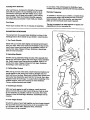
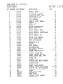
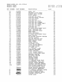
1
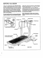
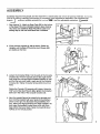
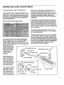
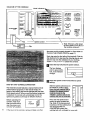
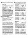
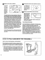
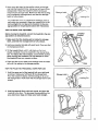
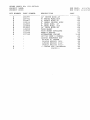
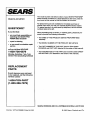
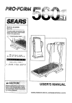
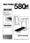
PRO.FORM"
SF_ARS
Model No. 831.297641
Serial No.
The serial number can be found in the
location shown below. Write the sedal
number in the space above.
Ex
E: R
EQUIPMENT
H
C
I='LPLIN
I S
I=-
E!
1-800-736-6879
USER'S MANUAL
SEARS, ROEBUCK AND CO., HOFFMAN ESTATES, IL 60179
PRO.FORM
TABLE OF CONTENTS •
IMPORTANT PRECAUTIONS .................................................................
BEFORE YOU BEGIN .......................................................................
ASSEMBLY ...............................................................................
3
4
5
OPERATION AND ADJUSTMENT .............................................................
HOW TO FOLD AND MOVE THE TREADMILL ..................................................
TROUBLE-SHOOTING
AND STORAGE ........................................................
CONDITIONING GUIDELINES ...............................................................
ORDERING REPLACEMENT PARTS ..................................................
FULL 90 DAY WARRANTY ...........................................................
Note: An EXPLODED
7
10
12
14
Back Cover
Back Cover
DRAWING and a PART LIST are attached to the center of this manual. Save the
EXPLODED DRAWING and PART LIST for future reference.
_WA__
_"
: R•N.l•
_.. +.:_'_ :_i:_'_":¸ _:;_"
:N:_:"_--'>i_ Beforel
_:_'_4_
::-.2":i:.::_:
_::_:" : :_: '
•
_'_;
beg[r_Ring
_ii_
; " ! ::::::_::_'!.:i:i_'_i_i_:':_
¸
:_ "_'_ _:i_!
_hla
o_ __'_
arly
_i_i;_exercise
i!_i;_ _
¸¸¸:::;::!¸%:¸;'¸" "::;_
•!
:!_
¸: :'progremi;:
" !_: _ ::_z_!i_ii_:_
consu_:_:_::_t_.yo_l_iph_
_ _ z: _:_i _::
.
"'.
:_.':'_:::
_:'_
_:
_:_
": i¸ :_
:__: _'_
I_|a_ _'_:':
;::_< _'_'_:_
:_:
|s_
_
_: :1_
,s _s_i_tly_l_ant
for per_ns over the age of35 or persons with _xi;_ing:
_i_i€_61_;_!_
_Read"'=;all
instructions: before using SEARS:::::assumes:
::'_':':_¢_:
':_no
:' i'espons=bdity:"
=::'::f0r
_::'_:_;_;_:_:_
_erso nal::'_
I_Ju
_'_"_
_! o_ pi_
_':_;_ __':__
_:damage S0Sta_ed by or throuqh the use of th=s product. :: :;,;_
2
_IMP
PRECAUTION=
3
BEFORE YOUBEGIN
Thank you for selecting the unique PROFORM ®580si
treadmill. The 580si treadmill blends advanced technology with innovative styling to let you enjoy an excellent
form of cardiovascular exercise in the convenience and
privacy of your home. The 580si offers an impressive
array of features to make your workouts more enjoyable and effect'we. And when you're not exemlsing, the
580si can be folded up, requidng less than half the floor
space of other treadmills.
For your benefit, read this manual carefully before
using the treadmill. If you-have additional questions,
Towel Rack
Water
Bottle*
Holder
please call our toll-free HELPLINE at 1-800-736-6879,
Monday through Saturday, 7 a.m. until 7 p.m. Central
Time (excluding holidays). To he!p us assist you,
please note the product model number and seriai number before-calling. The model number of the treadmill
is 831.297643. The serial number can be found on a
decal attached to the treadmill (see the front cover of
this manual for the location).
Before reading further, please review the drawing
below and familiarize yourself with the parts that are
labeled.
Console
Tray
*A Water Bottle is not included
Handrails
Belt
Circuit Breaker
Foot Rails
On/Off
Switch
Padded Walking Platform
for maximum comfort
FRONT
BACK
Leg
Rear Roller
Adjustment Bolt
4
RIGHT SIDE
ASSEMBLY
Assembly requires two people. Set the treadmill in a cleared area and remove all packing materials. Do not dispose of thepacking materials until assembly is completed. Tools required for assembly: The included allen
wren____
and your phillips
screwdriver
-======C_
1. See drawing 1A. Attach six Base Pads (95) to the bottom
of the Base (73) in the indicated locations (see drawing
1B). Note: One additional Base Pad will be used in assembly step 6, and one extra Base Pad is included.
and two adjustable
IA
wrenches
......
_.
1B
II
J
=__
.J
::':;..%96
2. Firmly hold the Uprights (6, 88) as shown. Raise the
Uprights until the Base (73) and the front Wheels (66)
are resting on the floor.
3. Loosen the Crossbar Bolts (1) in the ends of the Console
Crossbar (9). Pivot the Console (10) to the angle shown.
Look under the Left and Right Crossbar Brackets (3, 36)
and find the two small holes in each end of the Console
3
1o
Crossbar (9). Tighten Crossbar Screws (64) into all four
holes.
Rotate the Console (10) upward until it stops. Using the
7/32" end of the Allen Wrench (83), tighten the Crossbar
Bolts (1) in the ends of the Console Crossbar (9).
4. Next, the treadmill should be raised to the storage position. Hold the treadmill with your hands in the locations
shown at the right. To decrease the possibility of ino
jury, bend your legs and keep your back straight. As
you raise the treadmill, make sure to lift with your
legs rather than your back. Raise the treadmill about
halfway to the vertical position.
5
5. Move your right hand. to the position shown at the right,
and hold the treadmill firmly'. Using your left hand. !iff the
storage latch. Raise the treadmill until the locking pin
snaps into the storage latch. Make sure that the locking
pin is inside the storage latch, and that the storage
latch is fully closed.
6. See drawing 6B. Attach a Base Pad (95) to the bottom of
the Stabilizer Plate (98) in the indicated location.
5
6A
6B
See drawing 6A. Stand behind the treadmill. Hold the Left
Crossbar Bracket (3) and the Right Crossbar Bracket (not
shown). Place one fobt on the Base (73) in the indicated
location. Tip the treadmill back slightly. While the treadmill is held in this position, a second person should slide
the Stabilizer Plate (98) onto the Base (see drawing 6C).
Keeping your foot on the Base, carefully tip the treadmill
up until it is resting on the Base. Make sure that the
Stabilizer Plate (98) stays on the Base.
See drawing 6C. Attach the Stabilizer Plate (98) to the
Base (73) with a Stabilizer Plate Bolt (91), two Stabilizer
Plate Washers (70), and the Stabilizer Plate Nut (71) as
shown.
7. Refer to assembly drawing 5 at the top of this page. Hold
the upper end of the treadmill with your right hand as
shown. Using your left hand, lift the storage latch. Pivot
the treadmill slightly until the locking pin is out of the storage latch.
7
Hold the treadmill firmly with both hands, and lower the
treadmill to the floor. To decrease the possibility of injury, bend your legs and keep your back straight.
8. Remove thepaper backing from the Adhesive Clip (26).
Press the Adhesive Clip onto the Frame (49) in the indicated location. Press the Allen Wrench (83) into the
Adhesive Clip. The use of the Allen Wrench is described
on page 12.
Make sure that all parts are tightened before you use the
treadmill. Note: To protect the floor or carpet, place a
mat under the treadmill.
49
OPERATION
THE PERFORMANT
AND ADJUSTMENT
LUBE TM WALKING
BELT
Your treadmill features a walking belt coated with
PERFORMANT LUBE TM, a high-performance lubricant.
IMPORTANT: Never apply silicone spray or other
substances to the walking belt or the walking platform. They will deteriorate the walking belt and
cause excessive wear.
electric shock. This product is equipped with a cord
having an equipment-grounding conductor and a
grounding plug. Plug the power cord into a surge
protector, and plug the surge protector into an appropriate outlet that ls properly installed and
grounded in accordance with all local codes and
ordinances.
This product is for use on a 5omina1120-volt circuit,
and has a grounding plug that looks like the plug iUustrated in drawing I below. A temporary adapter that
looks like the adapter illustrated in drawing 2 may be
used to connect the surge protector to a 2-pole receptacle as shown in drawing 2 if _aproperly grounded outlet is not available.
HOW TO PLUG IN THE POWER CORD
The temporary adapter should be used only until a
properly grounded outlet (drawing 1) can be installed
by a qualified electrician.
The green-colored rigid ear, lug, or the like extending
from the adapter must be connected to a permanent
ground such as a propedy grounded outlet box cover.
Whenever the adapter is used it must be held in place
by a metal screw. Some 2-pole receptacle outlet box
covers are not grounded. Contact a qualified electrician to determine If the outlet box cover is
grounded before using an adapter.
Your treadmill, like any other type of sophisticated
electronic equipment, can be seriously damaged by
sudden voltage changes in your home's power.
Voltage surges, spikes, and noise interference can result from weather conditions or from other appliances
being tumed on or off.
To decrease the possibility of your treadmill being damaged,
./j_
G rounded Outlet Box
always use a surge
protector (not in_ _.J
!Grounding
Pin
cluded) with your
treadmill,
_'_unding
• Surge protectors are
sold at most hardware
stores and department
stores. Use only a ULlisted surge protector,
rated at 15 amps, with a
14-gauge cord of five
feet or less in length.
This product must be
grounded. If it should
malfunction or break
down, grounding provides a path of least resistance for electric current to reduce the risk of
Plug
_Grounded Outlet
_
Grounded Outlet Box
AdapteGrrounding
Pin
Plug
'ge Protector
Metal Screw
_
7
DIAGRAM OF THE CONSOLE
Mode
I
A
II11111
V
IIIII
Q
\
' Speed Control
--
\
_'Note:
If there is a thin sheet
\
of clear plastic on the face of
the console, remove it.
Clip
the power cord is properly plugged in. (See HOW TO
PLUG IN THE POWER CORD on page 7.)
Next, step onto the foot rails of the treadmill. Find the
clip attachedto the key (see the drawing above), and
slide the clip onto the waistband of your clothing•
Follow t"_ _teF:.s
be!_._,rto operate the console:
g
Insert the key fully Into the power switch.
The four displays
and the green MANUAL mode indicator
will light•
I_
/
I-
I_
_]
Reset the speed control and select a speed
setting.
STEP BY STEP CONSOLE OPERATION
The treadmill console features a manual mode and six
preset workout programs• In the manual mode, the
speed of the walking belt can be changed with the electronic speed control. When oneof the workout programs
is selected, the console will automatically control the
speed as it guides you through an effective workout.
console, make sure
that the on/off switch
Before
near
theoperating
power cord
the
is in the "on" position.
8
"On"
Position
I
If the key is in the console, remove it. Make sure that
Slide the speed controldown to
the 'RESET" position. Note'.
Each time the walkina belt is
stoooed, the soeed control
must be moved to the
"RESET" oositlon before the
walklna belt can be restarted.
o
--,.=1
ii
ii
II
I
II
!
I
II
I
II
I dLOsl
Next, slide the speed control
upward to select a speed set,., .IC:=::=_ •
ting. Note: If the key was just
RF.SL_'I
inserted, or if the walking belt
2 SJrF,_II[ED
was stopped with the
START/STOP button, the
walking belt will not begin to move yet.
B
Press
SELECT MODE button to select the
desiredthemode.
[L'_ Follow your progress with themonitor
displays.
The four monitor displays provide instant feedback:
When the key is inserted, the console will be in the
MANUAL mode.
If you want to select
one of the six preset
programs, press the
SELECT MODE button. The red PROGRAM A indicator
will light. To select PROGRAM B, C, D, E, or F, repeatedly preSS the SELECT MODE button.
Note: PROGRAMS A, B, and C are twenty-minute
programs; PROGRAMS D, E, and F are thirtyminute programs. The speed profiles in the center
of the console show how the speed of the walking
belt will change during the programs. During PROGRAM A, for example, the speed will gradually increase during the first ten minutes, and then gradually decrease during the last ten minutes. Each program will begin with a two-minute warm-up period,
and end with a two-minute cool-down period.
D
Press the START/STOP
START/STOP button
is pressed, the walk-
button.
pll
START
ing belt will begin to
A/STOP
move. Hold the
handrails and carefully begin walking on the walking belt.
If the console is in the manual mode, change the
speed of the walking belt as desired by sliding
the speed control. To stop the walking belt, slide the
speed control to the "RESET" position. The walking
belt can also be stopped by pressing the START/
STOP button; however, this will reset the displays.
If one of the preset programs is selected, the speed
setting you selected will be the minimum speed setting for the program. The speed of the walking belt
will then change automatically during the program as
shown by the speed profiles in the center of the console. When the program is completed, the walking
belt will automatically slow to.a stop. Note:.lf:th.eJm ............
tensity level of the program is too easy or too difficult,
adjust the speed control to select a new minimum
speed setting. To stop the program temporarily, slide
the speed control to the RESET" position. To restart
the program, slide the speed controlup to the desired
position. To terminate the program before the program is completed, preSS the START/STOP button. If
you select a different program while a program is
running, the walking belt will slow to a stop.
• CAL/FAT CAL display---Displays the
approximate numbers of Calories
and Fat Calories
you have burned
(see BURNING FAT on page 14). Every seven
seconds, the display will change from one number
to the other (an "P will appear when the number
of Fat Calories is shown). Note: The actual _urnber of Calories you have bumed may differ slightly
from the number shown if the speed or incline is
near the lowest or highest setting.
• TIME display-When the console
is in the manual
mode, the elapsed
time will be shown.
When one of the
preset programs is selected, the time remaining in
the program will be displayed.
• SPEED display-Displays the speed
of the walking belt,
in miles per hour
(MPH) or kilometers per hour (KPH).
Note: To change
the unit of measurement, hold
down the
START/STOP button while inserting
the key into the console. An "E" (for English system--miles per hour) or °M" (for Metric system-kilometers per hour) will appear in the DISTANCEJPULSE display. PreSSthe SELECT MODE
button to select the desired setting. Remove and
then reinsert the KEY. An MPH or a KPH will appear in the SPEED display to show which unit of
measurement you have selected.
_,DISTAJ_I_CFJ
.......... -tPULSE display-_TI
Displays the disyj
tanca you have
iwalked or run. If an L
MPH appears in
the SPEED display, the distance will be displayed
in miles. If a KPH appears, the distance will be displayed in kilometers. This display also shows your
pulse when the pulse sensor is used (see step 6).
9
r_
Measure your pulse, if desired.
B
To use the
Change the incline of the treadmill, if desired.
To change the incline, hold down
one of the incline
buttons until the
desired incline is
reached.
pulse sensor, stand
on the foot
rails and
place your
thumb on
D
the pulse
sensor as
shown.
The pulse sensor is pressure-activated. Fully press
down the pulse sensor. Do not press too herd, or
the circulation In your thumb will be restricted,
and your pulse will not be detected. Next, slightly
raise your thumb until the heart in the-DISTANCE/
PULSE display flashes steadily. Hold your thumb
at this level. After 5 to 10 seconds, your pulse will
be displayed. Hold your thumb on the sensor for
another 15 seconds for the most accurate reading.
If the displayed pulse appears to be too high or too
low, or if your pulse is not displayed, lift your thumb
off the sensor and allow the display to reset. Press
down again on the sensor as described above,
Make sure that your thumb is positioned as shown,
and that you are applying the proper amount of
pressure to the pulse sensor.
Try the sensor several times until you become familiar with it. Remember to stand still while measuring
your pulse.
V
.o
/NCUN£
When you are finished, remove the key.
Step onto the foot
rails and remove
the key from the
console. Store the
key in a secure
place. In addition,
move the on/off
switch to the "oft=' position. (See the drawing near
the bottomof page 8.)
THEINFORMATION
MODE
The console features an information mocle that keeps
track of the total time and distance accumulated on the
treadmill. To access this mode, hold down the
START/STOP button while inserting the key into the
console. The TiME display will show the total time. The
SPEED display will show the total distance (if the total
distance exceeds 999, the thousands and ten thousands digits will be shown in the CAL/FAT CAL display). The DISTANCE/PULSE display will show an "E"
or an "M," indicating miles or kilometers (see SPEED
DISPLAY on page 9). To exit the information mode, remove the key from the console.
HOW TO FOLD AND MOVE THE TREADMILL
HOW TO FOLD THE TREADMILL
A
FOR STORAGE
Before folding the treadmill for storage, unplug the power
cord. Caution: You must be able to safely lift 45 pounds
(20 kg) In order to raise, lower, or move the treadmill.
1. Hold thetreadmill with your I_ands in the locations shown
at the right. To decrease the possibility of injury, bend
your legs and keep your back straight. As you raise
the treadmill, make sure to lift with your legs rather
than your back. Raise the treadmill about halfway to the
vertical position.
2. Move your right hand to the position shown at the right,
and hold the treadmill firmly. Using your left hand, lift the
storage latch. Raise the treadmill until the locking pin
snaps into the storage latch. Make sure that the locking
pin is inside the storage latch, and that the storage
latch is fully closed.
Storage Latch
To protect the _!oor or carpet from damage, place a
mat under the treadmill. Keep the treadmill out of direct sunllght. Do not leave the treadmill in the storage posiUon in temperatures above 85 = Fahrenheit.
HOW TO MOVE THE TREADMILL
Crossbar
Bracket
Before moving the treadmill, convert the treadmill to the storage position as described above.
1. Make sure that the locking pin is inside the storage
latch, and that the storage latch is fully closed.
2; Hold one crossbar bracket with each hand. Place one foot
on the base as shown.
3. Tilt the treadmill back until it rolls freely on the front
wheels. Carefully move the treadmill to the desired location. To reduce the risk of injury, use extreme caution
while moving the treadmill. Do not attempt to move
the treadmill over an uneven surface.
4. Place one foot on the base, and carefully lower the treadmill until it is resting in the storage position.
HOW TO FOLD THE TREADMILL
DOWN FOR USE
1. Hold the upper end of the treadmill with your right hand
as shown. Using your left hand, lift the storage latch.
Pivot the treadmill slightly until the locking pin is out of
the storage latch. Make sure that the storage latch is fully
closed.
Storage Latch
2. Hold the treadmill firmly with both hands, and lower the
treadmill to the floor. To decrease the possibility of injury, bend your legs and keep your back straight.
11
TROUBLE-SHOOTING
AND STORAGE
Most treadmill problems can be solved by following the simple steps below. Find the symptom that applies, and follow the steps listed. If further assistance is needed, call our toll-free HELPLINE at 1-800-7366879, Monday through Saturday, 7 a.m. until 7 p.m. Central Time (excluding holidays).
1. SYMPTOM; THE POWER DOES NOT TURN ON
a. Make sure that the power cord is plugged into a surge protector, and that the surge protector is plugged into
a properly grounded outlet. (See HOW TO PLUG IN THE POWER CORD on page 7.) Use only a UL-listed
surge protector, rated at 15 amps, with a 14-gauge cord of five feet or less in length.
b. After the power cord has been plugged in, make sure that the key is fully inserted into the console. Vadous
indicators on the console should light (See step 1 page 8.)
c. Check the circuit breaker located on the treadmill near the
power cord. If the switch protrudes as shown, the circuit
breaker has tripped. To reset the circuit breaker, wait for five
minutes and then press the switch back in.
Reset
d. Check the on/off switch located at the front of the treadmill
near the power cord. The switch must be in the "on" position.
"On"
Position
2. SYMPTOM: THE POWER TURNS OFF DURING USE
a. Check the circuit breaker located on the treadmill frame near the power cord. If the circuit breaker has
tripped (see the drawing above), wait for five minutes and then press the switch back in.
b. Make sure that the power cord is plugged in.
c. Remove the key from the console. Reinsed the key fully into the console. (See step I on page 8.)
d. Check to make sure that the on/off switch is in the "on"position. (See 1. d. above.)
e. if the treadmill still will not run, please call our toll-free HELPLINE.
3. SYMPTOM: THE WALKING BELT SLOWS WHEN WALKED ON
a. Use only a UL-listed surge protector, rated at 15 amps, with a 14-gauge cord of five feet or less in length.
•b. If the walking belt still slows when walked on, please call our toll-free HELPLINE.
4; SYMPTOM: THE WALKING BELT IS OFF-CENTER OR SLIPS WHEN WALKED ON
a. If the walking belt has shifted to the left, first remove the key and
UNPLUG THE POWER CORD. Using the 3/16" end of the allen
wrench, turn the left rear roller adjustment bolt clockwise 1/4 of a
turn. Plug in the power cord, insert the key and run the treadmill
for a few minutes. Repeat until the walking belt is centered.
12
a
b. If the walking belt has shifted to the right, first remove the
SAFEKEY and UNPLUG THE POWER CORD. Using the 3/16"
allen wrench, turn the left rear roller adjustment bolt counterclockwise 1/4 of a turn. Plug in the power cord, insert the
SAFEKEY and run the treadmill for a few minutes. Repeat until
the walking belt is centered.
b
13
CONDITIONING
GUIDELINES
Training Zone (Beats/Min.)
The following guidelines will help you to plan youl:axercise program. Remember--these are general guidelines. For more detailed information about exercise,
obtain a reputable book or consult your physician.
EXERCISE INTENSITY
Whether you want to bum fat, strengthen your cardiovascular system, or increase your athletic performance, you can tailor your exercise to your specific
goals. The key to achieving the desired results is to exercise with the proper intensity.
Burning Fat
To bum fat effectively, you must exercise at a relatively
low intensity level for a sustained period of time.
During the first few minutes of exercise, your body
uses easily accessible carbohydrate ca/odes for energy. Only after the first few minutes of exercise does
your body begin to use stored fat calories for energy.
If your goal is to burn fat, set the speed control on the
console to FAT BURN to help you maintain the proper
intensity level. (See pages 8 and 9.)
Aerobic Exercise
If your goal is to strengthen your cardiovascular system, your exercise must be "aerobic." Aerobic exercise
is activity that requires large amounts of oxygen for
prolonged pedods of time. This increases the demand
on the heart to pump blood to the muscles, and on the
lungs to oxygenate the blood. The proper intensity
level for aerobic exercise can be found by using your
pulse as a guide. As you exercise, your pulse should
be kept at a level between 70% and 85% of your maximum possible heart rate. This is known as your training zone. You can find your training zone in the table
at the top of this page. Training zones are listed according to age and physical condition.
14
During the first few months of your exercise program,
Age
Unconditioned
Conditioned
20
138-167
133-162
25
136-166
132-160
30
135-164
130-158
35
134-162
129-156
40
132-161
127-155
45
131-159
125-153
50
129-156
124-150
55
127-155
122-149
60
126-153
121-147
65
125-151
11 9-145
70
123-150
118-144
75
122-147
117-142
80
120-146
115-140
85
119-144
114-139
keep your pulse near the low end of your training zone
as you exercise. After a few months of regular exercise, your pulse can be gradually increased until it is
near the middle of your training zone as you exercise.
You can measure your pulse using the pulse sensor.
Exercise for about four minutes, and then measure
your pulse immediately. If your pulse is too high or too
low, adjust the intensity of your exercise. It may also
be helpful to set the speed control on the console to
AEROBIC to help you maintain the proper intensity
level. (See pages 8 and 9.)
Performance Training
If your goal is high performance athletic conditioning,
set the speed control on the console to PERFORMANCE to help you maintain the proper intensity level.
(See pages 8 and 9.)
WORKOUT GUIDELINES
Each workout should include three parts: (1) a warmup, (2) training zone exercise, and (3) a cool-down.
Warm-up
Warming up prepares the body for exercise by increasing circulation, delivering more oxygen to the muscles
and raising the body temperature. Begin each workout
with 5 to 10 minutes of stretching and light exercise to
warm up (see SUGGESTED STRETCHES on page 15).
Training Zone Exercise
After warming up, increase the intensity of your exercise until your pulse is in your training zone for 20 to
50 minutes. (During the first few weeks of your exercise program, do not keep your pulse in your training
zone for longer than 20 minutes.) Breathe regulady
and deeply as you exemise--never hold your breath.
to cool down. This will increase the flexibility of your
muscles and will help to prevent post-exercise problems.
Exercise Frequency
To maintain or improve your condition, complete three
workouts each week, with at least one day of rest between workouts. After a few months, you may complete up to five workouts each week if desired.
Cool-down
Finish each workout with 5 to 10 minutes of stretching
SUGGESTED
The key to success is to make exercise a regu/ar and
enjoyab/e part of your everyday/fie.
STRETCHES
The correct form for several basic stretches is shown in the
drawings below. Move slowly as you stretch---never bounce.
1. Toe Touch Stretch
Stand with your knees bent slightly and slowly bend forward
from your hips. Allow your back and shoulders to relax as you
reach down toward your toes as far as possible. Hold for 15
counts, then relax. Repeat 3 times. Stretches: Hamstrings,
back of knees and back.
2
2. Hamstring Stretch
Sit with one leg extended. Bdng the sole of the opposite foot
toward you and rest it against the inner thigh of your extended
leg. Reach toward your toes as far as possible. Hold for 15
counts, then relax. Repeat 3 times for both legs. Stretches:
Hamstrings, lower back and groin.
3. Calf/Achilles
3
Stretch
With one leg in front of the other, reach forward and place your
hands against a wall. Keep your back leg straight and your
back foot flat on the floor. Bend your front leg, lean forward and
move your hips toward the wall. Hold for 15 counts, then relax.
Repeat 3 times for both legs. To cause further stretching of the
achilles tendons, bend your back leg as well. Stretches:
Calves, achilles tendons and ankles.
4. Quaddceps
Stretch
With one hand against a wall for balance, reach beck and
grasp one foot with your other hand. Bring your heel as close
to your buttocks as possible. Hold for 15 counts, then relax.
Repeat 3 times for both legs. Stretches: Quaddceps and hip
muscles.
f
5. Inner Thigh Stretch
Sit with the soles of your feet together and your knees outward.
Pull your feet toward your groin area as far as possible. Hold
for 15 counts, then relax. Repeat 3 times. Stretches:
Quadriceps and hip muscles.
15
REMOVE THIS EXPLODED DRAWING
AND PART LIST FROM THE MANUAL!
Save this EXPLODED DRAWING and PART LIST for future reference.
EXPLODED DRAWING--Model
No. 831.297641
Rg_B
21
27
2
23
13
84
45
46
47
4O
\
78
79
43
78
73
27
7O
67
SEARS MODEL NO:
PRODUCT
NAME:
PRODUCT
DESC:
KEY
NUMBER
1
2
3
4
5
6
7
8
9
i0
ii
12
13
14
15
16
17
18
19
20
21
22
23
24
25
26
27
28
29
30
31
32
33
34
35
36
37
38
39
40
41
42
43
44
45
46
47
48
49
50
51
52
53
54
PART
831.297641
RUN
RUN
NUMBER
119994
013282
127091
013322
119038
127739
129857
117988
130854
127984
105477
129672
126747
012108
126134
013547
122812
014117
123385
120867
129209
120785
107503
117882
100498
016028
120630
131219
127419
119163
126046
127847
128191
109365
015071
126641
112609
014127
124669
124695
126457
113203
131611
013162
129022
127698
128954
127700
NSP
106334
112669
124318
118570
113204
DESCRIPTION
CONSOLE
BOLT
CONSOLE
BRACKET
SCREW
LT CONSOLE
BRACKET
CONSOLE/ANCHOR
SCREW
SAFETY KEY/CLIP
LEFT UPRIGHT
WIRE HARNESS
CONSOLE
CABLE LOOM
CONSOLE
PLATE W/HDWR
CONSOLE
MOTOR NUT
MOTOR
PULLEY/FLYWHEEL/FAN
MOTOR PIVOT NUT
MOTOR BELT
MOTOR TENSION
BOLT
MOTOR TENSION
WASHER
MOTOR TENSION
STAR WASHER
MOTOR BOLT
MOTOR TENSION
NUT
FRONT HOOD
MOTOR MOUNT BRACKET
MOTOR SWIVEL BOLT
REED SWITCH/WIRE
MAGNET
ADHESIVE
CLIP
SCREW
WIRE CLIP
HOOD ANCHOR
ON/OFF
SWITCH
ELECTRONICS
BRACKET
CONTROLLER
POWER BOARD W/CLIPS
CHOKE
PLASTIC
STAND-OFF
RIGHT CONSOLE
BRACKET
FRONT ROLLER ADJ. BOLT
ADJUSTMENT
WASHER
POWER CORD
GRO_ET
SAFETY COVER WIRE HARNESS
SAFETY COVER CABLE LOON
SAFETY COVER
SAFETY COVER SCREW
FRONT ROLLER/PULLEY
WALKING
BOARD W/FASTENER
_
WALKING
BELT W/FASTENERS
FOOT RAIL W/FASTENERS
FRAME
HAIR PIN COTTER
COTTER PIN
BELT GUIDE
UPRIGHT
PIVOT WASHER
CABLE LOOM
DATE:
TIME:
COST
.oo
.oo
.oo
.oo
.oo
20.68
.oo
.oo
oo
oo
oo
oo
oo
oo
oo
oo
oo
oo
oo
oo
oo
.oo
.oo
.oo
.oo
.oo
.oo
.oo
.95
.oo
.oo
19.Ol
.oo
.oo
.oo
.oo
.oo
.oo
.oo
.oo
.oo
.oo
.oo
.oo
.oo
28.89
.oo
3.58
.oo
.oo
.00
.oo
.oo
.oo
6/19/96
11:23:58
SEARS MODEL NO:
PRODUCT
NAME:
PRODUCT
DESC:
KEY
NUMBER
831.297641
PART
RUN
RUN
NUMBER
DESCRIPTION
DATE:
TIME:
COST
..........................................................
55
56
57
58
59
60
61
62
63
64
65
66
67
68
69
70
71
72
73
74
75
012056
126635
125802
052014
013375
114270
126058
125855
013544
014132
013399
052012
012149
126735
128260
119425
114009
125758
126729
105444
127009
WHEEL NUT
UPRIGHT
PIVOT BOLT
RUBBER HOOD ANCHOR
FRONT WHEEL
INCLINE
LEG BOLT
INCLINE MOTOR SPACER
INCLINE
MOTOR
INCLINE
ROD
INCLINE
LEG BOLT
INCLINE
LEG WASHER
INCLINE
LEG WHEEL BOLT
INCLINE
LEG WHEEL
INCLINE
LEG NUT
INCLINE
LEG
RT REAR ADJUSTMENT
BOLT
BASE CROSSBAR
NUT
BASE CROSSBAR
BOLT
REAR HOOD
BASE CROSSBAR
LT REAR ADJUSTMENT
BOLT
REAR ROLLER
78
128986
RR
77
78
79
80
81
82
83
84
85
86
87
88
89
90
91
92
93
94
95
96
97
98
99
i00
123470
119439
129530
129168
127544
100691
126040
013141
016057
116927
109382
127741
045017
125871
110722
128119
112628
013300
126650
126960
111869
129004
014086
129673
-
6201ZZ
6201ZZ
SPRING SLEEVE
ROLLER TENSION
NUT
REAR ROLLER GUARD
HOOD SCREW
GUARD SPRING
PLATFORM
SCREW
3/16" ALLEN WRENCH
CROSSBAR
SCREW
8" WIRE TIE
TIE HOLDER
CLAMP
CIRCUIT
BREAKER
RIGHT UPRIGHT
7/32" ALLEN WRENCH
MOTOR CONTROLLER
WIRE
UPRIGHT
ENDCAP
BEVERAGE
HOLDER
WHEEL SPACER
ANCHOR
SCREW
UPRIGHT
FOOT
LT UPRIGHT
HOLE PLUG
CROSSMEMBER
CAGE NUT
SAFTEY COVER GROMMET
CONSOLE
BRACKET
WASHER
MTR/PULLEY/FLWHEEL/FAN
NON-ILLUSTRATED
PARTS
FRONT ROLLER BEARINGS
REAR ROLLER BEARINGS
LT CONSOLE
BRACKET
LATCH
LATCH WARNING
DECAL
CONSOLE
WARNING
DECAL
UPRIGHT
PIVOT NUT
SPEED KNOB
n
#
#
#
127711
124803
129312
ROLLER
TENSION
SPRING
.00
.00
.00
.00
00
00
00
00
00
00
00
00
00
00
00
00
O0
00
.00
00
.00
00
.00
00
.00
00
.00
00
.00
00
.00
00
.00
.00
.00
.00
.00
.00
.00
.00
.00
.00
.00
.00
.00
.00
.00
.00
.00
.00
.00
.00
.00
.00
6/19/96
11:23:58
SEARS MODEL NO: 831.297641
PRODUCTNAME:
PRODUCTDESC:
KEY
NUMBER
#
#
#
#
#
#
#
#
PART
NUMBER
101897
1077'71
109407
102634
112083
118304
114953
136838
133945
127744
127743
RUN DATE:
RUN
DESCRIPTION
14" WHITE WIRE,2F
8" WIIITE WIRE,M/F
4" BLACK WIRE,2F
8" GREEN GROUND
WIRE
8" BLUE WIRE, 3F
8" BLUE WIRE, M/F
14" BLUE WIRE,2F
TECH SHEET
TECH SHEET ENVELOPE
USER'S MANUAL
LITERATURE
PACKET
127744 USER'S
MANUAL
126842 HARDWARE
KIT
013141
2" SCREW
016028 WRENCH
CLIP
126040 WRENCH
3/16"
045017 WRENCH
7/32"
*_:_THESE ARE ESTIMATED
COSTS_I
TIME:
COST
.00
.00
.00
.00
.00
.00
.00
.00
.00
.72
3.00
.00
.00
.00
.00
.00
.00
.00
.00
6/19/96
11:23:58
Model No. 831.297641
QUESTIONS?
If you find that:
• you need he!p assembling or
operating the SEARS PROFORM" 580si treadmill
The model number and serial number of your SEARS PROFORIVP
580si treadmill are listed on a decal attached to the frame. See the
front cover of this manual to find the location of the decal.
All replacement parts are available for immediate purchase or
special order when you visit your nearest SEARS Service Center.
To request service or to order parts by telephone, call the toll-free
numbers listed at the left.
When requesting help or service, or ordering pads, please be prepared to provide the following information:
• The NAME OF THE PRODUCT (SEARS PROFORIVP 580si
treadmill)
• a part is missing
• The MODEL NUMBER OF THE PRODUCT (831.297641)
• or you need to schedule repair
service
call our toll-free HELPLINE
1-800-736-6879
Monday-Saturday,
7 am-7 pm
Central Time (excluding holidays)
• The PART NUMBER OF THE PART (see the EXPLODED
DRAWING and PART LIST attached to the center of this manual)
• The DESCRIPTION OF THE PART (see the EXPLODED DRAWING and PART LIST attached to the center of this manual)
REPLACEMENT
PARTS
If parts become wom and need
to be replaced, call the following
toll-free number
1-800-FON-PART
(1-800-366-7278)
SEARS, ROEBUCK AND CO., HOFFMAN ESTATES, IL 60179 USA
Part No. 127744 R995B Printed in USA
© 1995 Sears, Roebuck and Co.