1
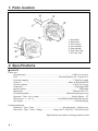
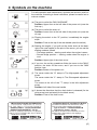
T2040-93111 (108)
OWNER / OPERATOR MANUAL
CHAINSAWS
G2500TS
WARNING
WARNING
The engine exhaust from this product
contains chemicals known to the State
of California to cause cancer, birth
defects or other reproductive harm.
Before using our products, please
read this manual carefully to
understand the proper use of your
unit.
APPLICABLE SERIAL NUMBERS :
100101 and up
SAFETY FIRST
Instructions contained in warnings within this
manual marked with a
symbol concern
critical points which must be taken into
consideration to prevent possible serious
bodily injury, and for this reason you are
requested to read all such instructions
carefully and follow them without fail.
■ WARNINGS IN THE MANUAL
WARNING
This mark indicates instructions which must be
followed in order to prevent accidents which could
lead to serious bodily injury or death.
IMPORTANT
This mark indicates instructions which must be
followed, or it leads to mechanical failure,
breakdown, or damage.
NOTE
This mark indicates hints or directions useful in the
use of the product.
1.
2.
3.
4.
5.
6.
7.
8.
9.
10.
11.
12.
CONTENTS
Parts location …………………………………4
Specifications …………………………………4
Symbols on the machine ……………………5
For safe operation ……………………………6
Installing guide bar and saw chain …………8
Fuel and chain oil ……………………………10
Operation ……………………………………12
Sawing ………………………………………16
Maintenance …………………………………19
Storage ………………………………………25
Troubleshooting guide ………………………26
Parts list ………………………………………27
1. Parts location
1.
2.
3.
4.
5.
6.
7.
Guide Bar
Saw Chain
Front Guard
Front Handle
Rear Handle
Fuel Tank Cap
Oil Tank Cap
2. Specifications
■ G2500TS
Power unit :
Dis placement ····················································································· 1.6(25.4) cu-in(cm3)
Fuel ············································································· Mixture(Gasoline 32 : 2-cycle oil 1)
Fuel tank capacity ················································································· 7.78(0.23) fl.oz( )
Chain oil ························································································ Motor oil SAE #10W-30
Oil tank capacity ···················································································· 5.42(0.16) fl.oz( )
Carburetor ································································································· Diaphragm type
lgnition system ··································································································· Solid-state
Spark plug ···························································································· Champion RCJ-7Y
Oil feeding system ····································································· Mechanical plunger pump
Sprocket : Pitch – No. of teeth ··························································· 3/8in(9.38mm) – 6T
Dimensions : L – W – H ············································ 10.4(260)x8.8(220)x8.8(220) in(mm)
Dry weight ································································································ 6.4(2.83) lbs(kg)
Cutting attachment :
Guide bar : Type – Size ····················································· Sprocket nose – 12(30) in(cm)
Saw chain : Type – Pitch – Gauge ··················· Oregon 91VG – 3/8(9.375) – 0.050(1.25) in(mm)
Specifications are subject to change without notice.
❲4 ❳
3. Symbols on the machine
For safe operation and maintenance, symbols are carved in relief on
the machine. According to these indications, please be careful not to
make a mistake.
(a). The port to refuel the "MIX GASOLINE"
Position: Upper-front at the left side of the power unit (near the
fuel cap )
(b). The port to refuel the chain oil
Position: Lower-front at the left side of the power unit (near the
oil cap)
(c). Flipping the switch to the "O" position, immediately the engine
stops.
Position: Front at the top of the rear handle (near the switch)
(d). Starting the engine, if you pull out the choke knob (at the backright of the rear handle) to the point of the arrow, you can set the
starting mode as follows
• First-stage position – starting mode when the engine is warm.
• Second-stage position – starting mode when the engine is
cool.
Position: Upper-right of the chain cover
(e). If you turn the rod by screwdriver follow the arrow to the "MAX"
position, the chain oil flow more, and if you turn to the "MIN"
position, less.
Position: Bottom of the power unit
(f). The screw under the "H" stamp is The High-speed adjustment
screw.
The screw under the "L" stamp is The Slow-speed adjustment
screw.
The screw at the left of the "T" stamp is the Idle adjustment
screw.
Position: Left side of the rear handle
(g). It shows the directions that the chain brake is released (for the
white arrow) and activated (for the black arrow).
Position: Front of the chain cover
IMPORTANT ENGINE INFORMATION
THI S ENG I NE CON FOR MS TO U S EPA
PH1 FOR SMALL OFF-ROAD ENGINES.
ENGINE FAMILY : YKZXS.0254DE:EM
ENGINE DISPLACEMENT : 25.4cc
REFER TO OWNER'S MANUMAL FOR MAINTENANCE SPECIFICATIONS AND ADJUSTMENTS.
MANUFACTURED :
RedMax
Made in Japan
INFORMATION IMPORTANTE CONCERNANT LE MOTEUR
Ce moteur conformc aux normcs U.S. EPA
PH1 pour les petits moteurs tout-terrain.
Type de moteur : YKZXS.0254DE:EM
Cylindrée du moteur : 25.4cc
Se référer au Manuel de l'utilisateur pour les
spécifications d'entretien et les réglages.
Manufacturé :
RedMax
Made in Japan
❲5 ❳
4. For safe operation
1. Never operate a chain saw when you are
fatigued, ill, or upset, or under the
influence of medication that may make
you drowsy, or if you are under the
influence of alcohol or drugs.
2. Use safety footwear, snug fitting clothing
and eye, hearing and head protection
devices.
3. Always use caution when handling fuel.
Wipe up all spills and then move the
chain saw at least ten(10)feet (three(3)
m) from the fueling point before starting
the engine.
3a) Eliminate all sources of sparks or
flame (ie. smoking, open flames, or
work that can cause sparks) in the
areas where fuel is mixed, poured, or
stored.
3b) Do not smoke while handling fuel or
while operating the chain saw.
4. Do not allow other persons to be near
the chain saw when starting the engine
or cutting a wood. Keep bystanders and
animals out of the work area. Children,
pets, and bystanders should be a
minimum of 30feet (10m) away when
you start or operate the chain saw.
5. Never start cutting until you have a clear
work area, secure footing, and planned
retreat path from the falling tree.
6. Always hold the chain saw firmly with
both hands when the engine is running.
Use a firm grip with thumb and fingers
encircling the chain saw handles.
7. Keep all parts of your body away from
the saw chain when the engine is
running.
❲6 ❳
8. Before you start the engine, make sure
the saw chain is not contacting anything.
9. Always carry the chain saw with the
engine stopped, the guide bar and saw
chain to the rear, and the muffler away
from your body.
10. Always inspect the chain saw before
each use for worn, Ioose, or changed
parts. Never operate a chain saw that is
damaged, improperly adjusted, or is not
completely and securely assembled. Be
sure that the saw chain stops moving
when the throttle control trigger is
released.
11. All chain saw service, other than the
items listed in the Operator’s Manual,
should be performed by competent chain
saw service personnel. (e.g., if improper
tools are used to remove the flywheel, or
if an improper tool is used to hold the
flywheel in order to remove the clutch,
structural damage to the flywheel could
occur which could subsequently cause
the flywheel to disintegrate).
12. Always shut off the engine before setting
it down.
13. Use extreme caution when cutting small
size brush and saplings because slender
material may catch the saw chain and be
whipped toward you or pull you off
balance.
14. When cutting a limb that is under
tension, be alert for spring back so that
you will not be struck when the tension in
the wood fibers is released.
15. Keep the handles dry, clean and free of
oil or fuel mixture.
4. For safe operation
16. Operate the chain saw only in well
ventilated areas. Never start or run the
engine inside a closed room or building.
Exhaust fumes contain dangerous
carbon monoxide.
17. Do not operate a chain saw in a tree
unless specially trained to do so.
19. When transporting your chain saw, make
sure the appropriate guide bar scabbard
is in place.
20. This chain saw is equipped with a spark
arrester built-in muffler. Periodically
check the arrester to keep it in good
order.
18. Guard against kickback. Kickback is the
upward motion of the guide bar which
occurs when the saw chain at the nose
of the guide bar contacts an object.
Kickback can lead to dangerous loss of
control of the chain saw.
KICKBACK SAFETY PRECAUTIONS FOR
CHAIN SAW USERS
– WARNING –
● Kickback may occur when the nose or tip of the guide bar touches an object, or when the
wood closes in and pinches the saw chain in the cut. Tip contact in some cases may
cause a lightning fast reverse reaction, kicking the guide bar up and back towards the
operator. Pinching the saw chain along the top of the guide bar may push the guide bar
rapidly back towards the operator. Either of these reactions may cause you to lose
control of the saw which could result in serious personal injury.
● Do not rely exclusively on the safety devices built into your saw. As a chain saw user you
should take several steps to keep cutting jobs free from accident or injury.
(1) With a basic understanding of kickback you can reduce or eliminate the element of
surprise. Sudden surprise contributes to accidents.
(2) Keep a good grip on the saw with both hands, the right hand on the rear handle, and
the left hand on the front handle, when the engine is running. Use a firm grip with
thumbs and fingers encircling the chain saw handles. A firm grip will help you reduce
kickback and maintain control of the saw. Don’t let go.
(3) Make certain that the area in which you’re cutting is free from obstructions. Do not let
the nose of the guide bar contact a log, branch, or any other obstruction which could
be hit while you are operating the saw.
(4) Cut at high engine speeds.
(5) Do not overreach or cut above shoulder height.
(6) Follow manufacturers sharpening and maintenance instructions for saw chain.
(7) Only use replacement bars and chains specified by the manufacturer or the
equivalent.
❲7 ❳
5. Installing guide bar and saw chain
SE1
A standard saw unit package contains the items as
shown below. (SE1)
(1) Power unit
(2) Guide bar
(3) Saw chain
(4) Plug wrench
Open the box and install the guide bar and the saw
chain on the power unit as follows.
WARNING
SE2
The saw chain has very sharp edges. Use
protective gloves for safety.
1. Pull the guard towards the front handle to check
that the chain brake is not on.
2. Loosen a nut and remove the chain cover.
3. Fix the hanger on the rear of power unit by
screw. (SE2)
(1) Hanger
SE3
4. Mount the guide bar then fit the saw chain
around the bar and sprocket.(SE3)
WARNING
Pay attention to the correct direc-tion of the
saw chain
5. Fit the chain tensioner nut into the lower hole of
the guide bar, then install the chain cover, and
fasten the mounting nut to finger tightness.
(SE3)(SE4)
SE4
(1) Hole
(2) Moving direction
(3) Chain tensioner nut
WARNING
When installing the chain cover, be sure to fit
the hook completely at the rear end of the
cover.
❲8 ❳
5. Installing guide bar and saw chain
SE5
6. While holding up the tip of the bar,adjust the
chain tension by turning the tensioner screw until
the tie straps just touch the bottom side of the
bar rail. (SE5)
(1) Chain tension adjusting screw
(a) Loosen
(b) Tighten
SE6
7. Tighten the mounting nut securely with the bar
tip held up (TORQUE: 11.8~14.7 N.m./120~150
kg-cm). Then check the chain for smooth
rotation and correct tension while moving it by
hand. If necessary, readjustment. (SE6)
(1) Tighten
WARNING
It is very important to maintain the proper chain
tension. Rapid wear of the guide bar or the
chain coming off easily can be caused by
improper tension. Especially when using a new
chain, take good care of it since it should
expand when first used.
❲9 ❳
6. Fuel and chain oil
■ FUEL
The RedMax engines are lubricated by oil specially
formulated for air-cooled 2-cycle gasoline engine
use. If RedMax oil is not available, use an antioxidant added quality oil expressly labeled for aircooled 2-cycle engine use.
RECOMMENDED MIXING RATIO
GASOLINE 32 : OIL 1
Exhaust emission are controlled by the
fundamental engine parameters and
components (eq., carburation, ignition timing
and port timing) without addition of any major
hardware or the introduction of an inert
material during combustion.
These engines are certified to operate on
unleaded gasoline.
WARNING
The fuel is highly flammable. Do not smoke or
bring any flame or sparks near fuel.
■ HOW TO MIX FUEL
1. Measure out the quantities of gasoline and oil to
be mixed.
2. Put some of the gasoline into a clean, approved
fuel container.
3. Pour in all of the oil and agitate well.
4. Pour in the rest of gasoline and agitate again for
at least one minute.
5. Put a clear indication on the outside of the
container to avoid mixing up with gasoline or
other containers.
FOR YOUR ENGINE LIFE, AVOID;
1. FUEL WITH NO OIL(RAW GASOLINE) – It will
cause severe damage to the engine inner parts
very quickly.
2. GASOHOL – It can cause deterioration of rubber
and/or plastic parts and disruption of engine
lubrication.
3. OIL FOR 4-CYCLE ENGINE USE or WATER
COOLED 2-CYCLE ENGINE USE – It can
cause spark plug fouling, exhaust port blocking,
or piston ring sticking.
❲ 10 ❳
6. Fuel and Chain oil
■ CHAIN OIL
Use motor oil SAE 10W-30 all year round, or SAE
30-40 in summer and SAE 20 in winter.
NOTE
Do not use waste or regenerated oil that can cause
damage to the oil pump.
❲ 11 ❳
7. Operation
OP1
■ STARTING ENGINE
1. Feed fuel and chain oil into their respective
tanks and tighten the caps securely. (OP1)
(1) Fuel
(2) Chain oil
OP2
OP3
2. Continuously push the priming bulb until fuel
comes in the bulb. (OP2)
3. Put the switch to the "I" position. (OP3)
(1) Switch
OP4
OP5
4. Pull out the choke knob to the second-stage
position. The choke will close and the throttle
lever will then be set in the starting position.
(OP4,5)
(1) Throttle lever
(2) Throttle interlock
(3) Choke knob
(a) when the engine is cool
(b) when the engine is warm up
(c) after the engine starts
NOTE
When restarting immediately after stopping the
engine. Choke knob in the first-stage position
(choke open and throttle lever in the starting
position)
❲ 12 ❳
7. Operation
NOTE
OP6
Once the choke knob has been pulled out, it will
not return to the operating position even if you
press down on it with your finger. When you wish
to return the choke knob to the operating position,
pull out the throttle lever instead.
5. While holding the saw unit securely on the
ground, pull the starter rope vigorousl y. (OP6)
6. When firing occur, push in the choke knob and
pull the starter again to start the engine.
7. Allow the engine to warm up with the throttle
lever pulled slightly.
WARNING
Before you start the engine, make sure the saw
chain is not contacting anything.
OP7
■ CHECKING OIL SUPPLY
After starting the engine, run the chain at medium
speed and see if chain oil is scattered off as shown
in the figure. (OP7)
(1) Chain oil
OP8
The chain oil flow can be changed by inserting a
screwdriver in the hole on bottom of the clutch
side. Adjust according to your work conditions.
(OP8)
(1) Chain oil flow adjusting shaft
(a) Rich
(b) Lean
NOTE
The oil tank should become nearly empty by the
time fuel is used up. Be sure to refill the oil tank
every time when refueling the saw.
❲ 13 ❳
7. Operation
■ ADJUSTING CARBURETOR (OP9)
The carburetor on your unit has been factory
adjusted, but may require fine tuning due to
change in operating conditions.
Before adjusting the carburetor, make sure that
provided are clean air/fuel filters and fresh,
properly mixed fuel.
When adjusting, take the following steps:
NOTE
Be sure to adjust the carburetor with the bar chain
attached.
1. H and L needles are restricted within the number
of turn as shown below.
OP9
H needle –1/4
L needle –1/4
2. Start engine and allow it to warm up in low
speed for a few minutes.
3. Turn idle adjusting screw (T) counter-clockwise
so that saw chain does not turn. If idling speed is
too slow, turn the screw clockwise.
4. Make a test cut adjust the H needle for best
cutting power, not for maximum speed.
(1) L needle
(2) H needle
(3) Idle adjusting screw
■ CHAIN BRAKE (OP10)
The chain brake is a device which stops the chain
instantaneously if the chain saw recoils due to
kickback.
Normally, the brake is activated automatically by
inertial force. It can also be activated manually by
pushing the brake lever (left-hand guard) down
toward the front.
When the brake operates, a yellow cone pops up
from the base of the brake lever.
Releasing the Brake
Pull the brake lever up toward the left-hand handle
until it clicks into place.
❲ 14 ❳
7. Operation
WARNING
• When the brake operates, release the throttle
lever to slow down the engine speed.
Continuous operation with the brake
engaged will generate heat from the clutch
and may cause trouble.
• At machine inspection prior to each job,
check the operating condition of the brake
following the steps below.
OP10
1. Start the engine and grasp the handle securely
with both hands.
2. Pulling the throttle lever to maintain the chain
operation, push the brake lever (left-hand guard)
down toward the front using the back of your left
hand.
3. When the brake operates and the chain is
stopped, release the throttle lever.
4. Release the brake.
(1) Releases the brake.
(2) Activates the brake.
OP11
■ STOPPING ENGINE
1. Release the throttle lever to allow the engine
idling for a few minutes
2. Put the switch to the "O" position. (OP11)
(1) Switch
❲ 15 ❳
8. Sawing
WARNING
• Before proceeding to your job, read "For
Safe Operation" section It is recommended
to first practice sawing easy logs. This also
helps you get accustomed to your unit.
• Always follow the safety regulations. The
chain saw must only be used for cutting
wood. It is forbidden to cut other types of
material. Vibrations and kickback vary with
different materials and the requirements of
the safety regulations would not be
respected. Do not use the chain saw as a
lever for lifting, moving or splitting objects.
Do not lock it over fixed stands. It is
forbidden to hitch tools or applications to the
P.t.o. that are not specified by the
manufacturer.
• It is not necessary to force the saw into the
cut. Apply only light pressure while running
the engine at full throttle.
• When the saw chain is caught in the cut, do
not attempt to pull it out by force, but use a
wedge or a lever to open the way.
SA1
■ Guard against kickback (SA1)
• This saw is equipped with a chain brake that will
stop the chain in the event of kickback if
operating properly. You must check the chain
brake operation before each usage by running
the saw at full the throttle for I -2 seconds and
pushing the front hand guard forward. The chain
should stop immediately with the engine at full
speed. If the chain is slow to stop or does not
stop, replace the brake band and clutch drum
before use.
• It is extremely important that the chain brake be
checked for proper operation before each use
and that the chain be sharp in order to maintain
the kickback safety level of this saw. Removal of
the safety devices, inadequate maintenance, or
incorrect replacement of the bar or chain may
increase the risk or serious personal injury due
to kickback.
❲ 16 ❳
8. Sawing
SA2
■ FELLING A TREE (SA2)
WARNING
When you fell a tree, be sure to warn your
neighboring workers of the danger.
1. Decide the felling direction considering the
wind, Iean of the tree, location of heavy
branches, ease of job after felling, and
other factors .
2. While clearing the area around the tree,
arrange a good foothold and retreat path.
3. Make a notch cut one-third of the way into
the tree on the felling side.
4. Make a felling cut from the opposite side
of the notch and at a level slightly higher
than the bottom of the notch.
■ LOGGING AND LIMBING
WARNING
1. Always ensure your foothold as well as
stability of the tree.
2. Be alert to the rolling over of a cut log.
3. Read the instructions in “For safe
operation” to avoid kickback of the
saw.
Before starting work, check the direction of
bending force inside the log to be cut.
Always finish cutting from the opposite side
of bending direction to prevent the guide bar
from being caught in the cutaway.
SA3
● Cutting an unpillowed log
Saw down halfway, then roll the log over and
cut from the opposite side. (SA3)
❲ 17 ❳
8. Sawing
SA4
● Cutting a pillowed log
In the area A in the picture right above, saw up
from the bottom one-third and finish by sawing
down from the top. In the area B, saw down from
the top one-third and finish by sawing up from the
bottom. (SA4)
● Limbing a felled tree
SA5
WARNING
Be alert to the spring back of a cut limb.
First check which way the limb is bent. Then make
a shallow cut into the compressed side to prevent
the limb from being torn. Cut through from the
tensed side. (SA5)
SA6
● Pruning
WARNING
1. Do not use an unstable foothold or a
stepladder.
2. Do not overreach.
3. Do not cut above shoulder height.
4. Always use both hands to grip the saw.
Cut up from the bottom, finish down from the top.
(SA6)
❲ 18 ❳
9. Maintenance
WARNING
MA1
Make sure the engine is stopped .
■ DAILY CHECK POINTS
1. Air filter
Loosen the knob and remove the air cleaner cover.
Take off the filter elements and tap off attached
sawdust. When they are extremely dirty,
shakewash with gasoline. Dry them completely
before reinstalling. (MA1)
MA2
2. Oiling port
Dismount the guide bar and check the oiling port
for clogging. (MA2)
(1) Oiling port
MA3
3. Guide bar
Remove sawdust in the bar groove and the oiling
port. (MA3)
(1) Groove
(2) Oiling port
MA4
(Type: Sprocket nose)
Grease the nose sprocket from the feeding port on
the tip of the bar. (MA4)
(1) Grease port
(2) Sprocket
4. Others
Check for fuel leakage and loose fastenings or
damage to major parts, especially handle joints
and guide bar mounting. If any defects are found,
make sure to have them repaired before operating
again
❲ 19 ❳
9. Maintenance
WARNING
This saw is equipped with one of the following
low kickback bar/chain combinations:
RedMax Part Number
Bar Size
Guide Bar
Saw Chain
12inch (30cm)
G2512
91VG45X
For replacement, use only above bar and chain,
or the following;
OREGON BAR
12 inch S/N DOUBLE GUARD BAR,
Mount code #A041. (120 SDEA 041)
GB BAR
12 inch MINI LAMINATED BAR (PO12-50CR)
MA5
OREGON CHAIN
91VG
■ PERIODICAL CHECK POINTS
1. Cylinder fins
1. Remove the starter case.
2. Remove sawdust between the cylinder fins.
(MA5)
MA6
(1) Cylinder fin
2. Fuel filter
1. Using a wire hook, take out the fuel filter from
the feeding port. (MA6)
2. Wash the filter with gasoline.
Replace with new one if clogged with dirt
completely.
WARNING
MA7
When returning the filter, use a pinch not to be
folded the suction pipe.
3. Oil filter
1. With a wire hook, take out the oil filter from
the feeding port. (MA7)
2. Wash the filter with gasoline.
❲ 20 ❳
9. Maintenance
WARNING
When returning the filter, use a pinch not to be
folded the suction pipe.
MA8
4. Spark plug
Clean the electrodes with a wire brush and adjust
the gap to 0.6mm. (MA8)
Replacement plug:
Champion RCJ-7Y
WARNING
MA9
After spark plug maintenance, reinstall the plug
and plug cap firmly. (TORQUE: 14.7~17.6
N.m./150~180 kg-cm) Or it may cause the fire
accident. (MA9)
(1) Plug
(2) Plug cap
MA10
MA11
5. Sprocket
Check for extensive wear, and replace it when the
teeth are worn over 1.0mm. (MA10)
6. Guide bar
The bar rail should always be a square. Check for
wear of the bar rail. Apply a ruler to the bar and the
outside of a cutter. If a gap is observed between
them, the rail is normal. Otherwise, the bar rail is
worn. Such a bar needs to be corrected or
replaced.(MA11)
(1) Ruler
(2) Gap
(3) No gap
(4) Chain tilts
❲ 21 ❳
9. Maintenance
7. Saw Chain
WARNING
MA12
It is very important for smooth and safe
operation to keep the cutters always sharp.
Your cutters need to be sharpened when:
• Sawdust becomes powder-like.
• You need extra force to saw in.
• The cut way does not go straight.
• Vibration increases.
• Fuel consumption increases.
Cutter setting standards:
WARNING
Be sure to wear safety gloves.
Before filing:
• Make sure the saw chain is held securely.
• Make sure the engine is stopped.
• Use a round file of proper size for your chain.
Chain type:
91VG
File size:
5/32 in (4.0mm)
MA13
Place your file on the cutter and push straight
forward. Keep the file position as illustrated.
(MA12)
After every cutter has been set, check the depth
gauge and file it to the proper level as illustrated.
(MA13)
WARNING
Be sure to round off the front edge to reduce
the chance of kickback or tie-strap breakage.
(1) Appropriate gauge checker
(2) Make the shoulder round
(3) Depth gauge standard
❲ 22 ❳
9. Maintenance
MA14
Make sure every cutter has the same length and
edge angles as illustrated. (MA14)
(4) Cutter length
(5) Filing angle
(6) Side plate angle
(7) Top plate cutting angle
8. Way of the cooling air
WARNING
MA15
• The engine metal parts can burn your skin.
Never touch the cylinder, muffler or ignition
plug etc. during operation or right after
stopping the engine.
• Before starting the engine, check around the
muffler and take off sawdust. If you do not, it
will cause the overheating and a fire. For
preventing the trouble, please keep clean
around the muffler.
This engine is air-cooled. Dust clogging between
the inlet port of the cooling air and cylinder fins will
cause overheating of the engine. Periodically
check and clean the cylinder fins after removing
the air cleaner and the cylinder cover. (MA15)
(1) Inlet port of the cooling air
IMPORTANT
When installing the cylinder cover, make sure that
switch wires and grommets are positioned correctly
in place.
❲ 23 ❳
9. Maintenance
9. Muffler (MA16)
WARNING
If you do not attach the muffler correctly, after
engine starts, the muffler will be loosen and the
hightemperature exhaust gas spout. After
cleaning the muffler, pay attention to fit up the
muffler according to the explanation as follows.
MA16
1. Muffler body, muffler cover and baffle will be
combined correctly.
2. Be sure the gasket is not broken. If it is broken,
change to the new one.
3. Before tightening the screw, rub the gross on it.
4. After making a test run, re-tighten the screw
(TORQUE: 4.9~5.9 N.m./50~60 kg-cm)
WARNING
Right after stopping the engine, do not touch
the muffler with one's bare hands. It will cause
to burn your hands.
If carbon clogs between the muffler, it will cause
the poor-output and the trouble in starting. After
each 100 hours, check and clean inside the
muffler.
Spark arrester
RedMax engines are equipped with a spark
arresting screen at the exhaust port. Periodically
check and keep it in good condition. In the State of
California it is required by law (Section 4442 of the
California Public Resources Code) to have a spark
arrester when a gas powered tool is used in any
forest covered, brush covered, or grass covered
unimproved land. (MA16)
(1) Gasket
(2) Spark arrester
❲ 24 ❳
10. Storage
1. Empty the fuel tank and run the engine out of
fuel.
2. Empty the oil tank.
3. Clean the entire unit.
4. Store the unit in a dry place out of the reach of
children.
❲ 25 ❳
11. Troubleshooting Guide
Case 1. Starting failure:
Make sure the icing prevention system is not working.
Check fuel for water or
substandard mixture.
Replace with proper fuel.
➜
Remove and dry the spark plug.
Then pull the starter again with no choke.
➜
Replace with a new plug.
➜
➜
Check for engine flooding.
➜
Check the spark.
Case 2. Lack of power/Poor acceleration/Rough idling
Check fuel for water or
substandard mixture.
Replace with proper fuel.
➜
Clean.
➜
Readjust speed needles.
➜
Replace.
➜
Clean.
➜
➜
Check air filter and fuel
filter for clogging.
➜
Check carburetor for
inadequate adjustment.
Case 3. Oil does not come out
Check oil for
substandard quality.
➜
Check oil passage
and ports for clogging.
When your unit seems to need further service, please consult with our
service shop in your area.
❲ 26 ❳
12. Parts list
CHAINSAWS
G2500TS
NOTE :
1. Use KOMATSU ZENOAH genuine parts as specified in the parts list for repair and/or
replacement.
2. KOMATSU ZENOAH does not warrant the machines, which have been damaged by the
use of any parts other than those specified by the company.
3. When placing parts orders for repair and/or replacement, check if the model name and the
serial number are applicable to those specified in the parts list, then use parts number
described in the parts list.
4. The contents described in the parts list may change due to improvement.
5. The parts for the machine shall be supplied seven (7) years after the machine is
discontinued. [It is possible that some specific parts may be subject to change of their
delivery term and list price within the limit of ten (7) years after the machine is
discontinued. It is also possible that some parts may be available even after the limit of
seven (7) years.]
APPLICABLE SERIAL NUMBERS :
100101 and up
June 2001
❲ 27 ❳
12. Parts list
❲ 28 ❳
Fig.1 POWER UNIT G2500TS (S/N 100101 and up)
G2500TS
PART NUMBER
DESCRIPTION
Q'TY
/UNIT
CYLINDER COMP
• ELBOW
PIPE
CLIP
ELBOW
CRANKCASE
BOLT, hexagon hole
PISTON
RING, piston
PIN
RING, snap
BEARING
WASHER
SHAFT COMP
BEARING
OIL SEAL
OIL SEAL
NUT
KEY
PIPE SET
1
1
1
1
1
1
4
1
1
1
2
1
2
1
2
1
1
1
1
1
22
0263-30416
23 T2040-15100
24 T2040-15140
25
2841-15210
26
2670-82210
27 T2040-15310
28
2841-71101
29
2841-71120
30
1260-71240
31
2850-71140
32
2850-71151
33
2841-71200
34
2841-71220
35
2616-71320
36
2850-72110
37
1400-72121
38
1140-72110
39
5500-72150
40
3350-14150
41
1630-73110
42
2850-74102
43
2850-74213
44
2841-74220
45
2841-31106
46
2841-31141
47
2870-31750
48
2841-31202
49
2841-31210
50
2841-31252
51
1850-85300
52
2841-31280
53
2850-34501
54
3317-85120
55
2850-81900
SCREW
MUFFLER ASSY
• SPARK ARRESTER
GASKET
SCREW
MUFFLER COVER
ROTOR ASSY
• PAWL
• SPRING
• SCREW
• WASHER
MODULE ASSY
• CORD
• CAP
• CAP
• SPRING
• GROMMET
SPACER
BOLT, hexagon hole
SPARK PLUG
SWITCH ASSY
CORD
CORD
CASE COMP
• SCREW
SCREW
PIPE ASSY
• PIPE
• GROMMET
• FILTER
• COLLAR
BREATHER ASSY
GROMMET
PUMP
2
1
1
1
2
1
1
2
2
2
2
1
1
1
1
1
1
2
2
1
1
1
1
1
2
4
1
1
1
1
1
1
1
1
M5x20
M8x1.0
M4x16
M4x25
RCJ7Y
M5x16
Key#
PART NUMBER
DESCRIPTION
Q'TY
/UNIT
56
2841-31260
57
2841-31801
58
2841-31820
59
3330-23121
60
2841-31410
61
2841-31911
62
2630-31950
63
2841-31921
64
2841-37111
65
2841-37121
66
2841-37150
67
2841-31300
68
2841-31311
69
3310-57320
70
2841-31330
71
3310-57340
72
2670-23131
73
1260-41320
74
2841-55103
75
2841-55112
76
2850-55121
77
0263-30416
78
2850-55211
79
2670-55220
80
2841-55250
81
2841-55310
82
2630-31950
83
2475-51110
84
2475-51100
85
2475-51220
86
2841-51230
87
2475-51240
88
2841-51210
89
3310-51310
90 T2040-31950
91
2841-82510
92
2841-82411
93
2841-82421
94 T2040-81000
95
2841-82210
96
2841-82112
97
2841-82120
98
0263-30545
99
2841-83111
100
2841-83120
101
2841-83303
102
2841-83320
103
2841-83330
104
2630-53412
105
2630-32170
106
2841-53310
PIPE
CAP ASSY
• GASKET
VALVE
SEAL
COVER
SCREW, tapping
MAT
PIPE
PIPE
JOINT
PIPE COMP
• PIPE
• JOINT
• PIPE
• CLIP
• FILTER
• RING
OIL PUMP ASSY
• OIL PUMP
• WORM
SCREW
WASHER
SEAL
PIPE
COVER
SCREW, tapping
DRUM
CLUTCH ASSY
• SHOE
• SPRING
• BOSS
PLATE
BEARING
LABEL (EPA)
ROD
ROD
GROMMET
CARBRETOR ASSY
SEAL
PLATE
PLATE
SCREW
CLEANER
ELEMENT
COVER COMP
• KNOB
• GROMMET
CATCHER
SCREW, tapping
PLATE
1
2
2
1
1
1
2
1
2
1
2
1
1
1
1
1
1
1
1
1
1
2
1
1
1
1
2
1
1
2
2
1
1
1
1
1
1
1
1
1
1
1
2
1
1
1
1
1
1
1
1
108
109
110
STARTER ASSY
• CASE COMP
• REEL
1
1
1
2841-75001
2841-75101
2841-75210
NOTE
ø4.3x16
M4x16
ø4.3x16
WT-596
M5x45
ø5.4x20
Key#
PART NUMBER
111
2841-75300
112
1850-75160
113
3330-75421
114
1140-51230
115
2630-75510
116
2841-75611
117
2841-75710
118
2630-31950
119
2630-31950
120 T2040-75131
121
2841-54004
122
2841-54113
123
2841-54121
124
2872-54120
125
0263-80530
126
2872-54140
127
2850-54211
128
2851-54222
129
2841-54230
130
2851-54270
131 01641-20508
132
3310-53331
133
2851-54301
134
2851-54350
135
2670-54410
136
2841-54510
137
3356-24140
138
2670-54610
139
2841-54620
140
2630-33610
141
2841-53211
142
2841-53240
143
2810-53221
144
2671-53230
145
3350-53410
146 T2040-53121
147 T2040-54911
148
2841-32101
149
2841-32151
150
2841-35110
151
2630-75510
152
2630-75510
153
2841-33100
154
3356-33311
155
3356-33321
156 04025-00524
157
2841-35180
158
3356-33352
159
2841-34110
160
2630-31950
161
2841-35110
162
2841-35120
163
2841-35150
164
2841-98210
165
2630-33610
DESCRIPTION
• SPRING COMP
• ROPE
• KNOB
• WASHER
• SCREW, tapping
• COVER
• PIPE
• SCREW, tapping
SCREW, tapping
LABEL
BRAKE ASSY
• COVER
• GUARD
• SPRING
• SCREW
• SPACER
• SPACER
• WEIGHT
• SPRING
• SPRING
• WASHER
• NUT, nylon
• LEVER COMP
• ROLLER
• ARM
• BAND
• ROLLER
• SPRLNG
• COVER
• SCREW, tapping
• PLATE
• SCREW
• NUT
• GEAR
NUT
LABEL
LABEL, warning
HANDLE ASSY
• STOPPER
• DAMPER
• SCREW, tapping
SCREW, tapping
HANDLE COMP
• LEVER THROTTLE
• SPRING
• SPRING PIN
STOPPER
ARM
COVER
SCREW, tapping
DAMPER
BOLT
CAP
HANGER
SCREW
Q'TY
/UNIT
1
1
1
1
1
1
1
1
4
1
1
1
1
1
1
1
1
1
1
1
1
1
1
1
1
1
1
1
1
4
1
1
1
1
1
1
1
1
1
1
1
2
1
1
1
1
1
1
1
1
2
3
3
1
1
NOTE
ø5.4x14
ø4.3x16
ø4.3x16
M5x30
M5
ø4.3x12
M8
ø5.4x14
ø5.4x14
ø4.3x16
G2500TS
❲ 29 ❳
1 T2046-12100
2
2841-12120
3
2841-12210
4
3310-82230
5
3350-34320
6
2841-21110
7 01252-30520
8
2841-41112
9
2841-41210
10
1600-41310
11
1260-41320
12
5500-41410
13
1101-41340
14
2841-42001
15
1155-21240
16 T2041-21210
17 T2041-21220
18
1650-43230
19
1000-43240
20
2841-06011
NOTE
Fig.1 POWER UNIT (S/N 100101 and up)
Key#
12. Parts list
Fig.2 CARBBURETOR COMPONENTS & ACCESSORIES (S/N 100101 and up)
❲ 30 ❳
G2500TS
G2500TS
Fig.2 CARBBURETOR COMPONENTS & ACCESSORIES (S/N 100101 and up)
Key# PART NUMBER
DESCRIPTION
1 T2040-81000
2 2630-81120
3 3310-81130
4 3310-81280
5 1480-81420
6 3350-81380
7 2630-81330
8 2880-81470
9 3310-81341
10 2670-81410
11 T2040-81370
12 2841-81440
13 1148-81390
14 3310-81360
15 3310-81351
16 2841-06030
17 2850-06020
18 ––––––––––
19 ––––––––––
20 ––––––––––
21 ––––––––––
22 ––––––––––
23 ––––––––––
24 3320-91140
25 2670-91150
26 1030-91340
27 3350-96220
28 3350-96240
29 3304-97611
30 2670-96410
31 2841-96110
CARBURETOR ASS'Y
• PUMP COVER
• SCREW
• COVER
• PLUG
• SPRING
• SCREW
• SCREW
• VALVE
• SPRING
• SHAFT ASS'Y
• LEVER
• RING
• SCREW
• SCREW
• REBUILT KIT
• • GASKET KIT
• • SCREEN
• • VALVE, inlet
• • SPRING
• • PIN
• • LEVER
• • SCREW
WRENCH
DRIVER
DRIVER
STOPPER
GAUGE
WRENCH
WRENCH
WRENCH
Q'TY
/UNIT
1
1
1
1
1
1
1
1
1
1
1
1
1
4
1
1
1
1
1
1
1
1
1
1
1
1
1
1
1
1
NOTE
PISTON (OP)
AIR GAP (OP)
HEXAGON (OP)
TORX (OP)
CLUTCH (OP)
❲ 31 ❳
CALIFORNIA EMISSION CONTROL WARRANTY STATEMENT
YOUR WARRANTY RIGHTS AND OBLIGATIONS
THE CALIFORNIA AIR RESOURCES BOARD AND KOMATSU ZENOAH Co. ARE PLEASED TO
EXPLAIN THE EMISSION CONTROL SYSTEM WARRANTY ON YOUR 1995 AND LATER LAWN AND
GARDEN EQUIPMENT ENGINE. IN CALIFORNIA, NEW UTILITY AND LAWN AND GARDEN
EQUIPMENT ENGINES MUST BE DESIGNED, BUILT AND EQUIPPED TO MEET THE STATE'S
STRINGENT ANTI-SMOG STANDARDS.
KOMATSU ZENOAH Co, MUST WARRANT THE EMISSION CONTROL SYSTEM ON YOUR LAWN AND
GARDEN EQUIPMENT ENGINE FOR THE PERIODS OF TIME LISTED BELOW PROVIDED THERE HAS
BEEN NO ABUSE, NEGLECT OR IMPROPER MAINTENANCE OF YOUR LAWN AND GARDEN
EQUIPMENT ENGINE.
YOUR EMISSION CONTROL SYSTEM. MAY INCLUDE PARTS SUCH AS THE CARBURETOR, THE
IGNITION SYSTEM, AND CATALYTIC CONVERTER. ALSO INCLUDED MAY BE THE HOSES, BELTS,
CONNECTORS AND OTHER EMISSION-RELATED ASSEMBLIES.
WHERE A WARRANTABLE CONDITION EXISTS, KOMATSU ZENOAH Co. WILL REPAIR YOUR LAWN
AND GARDEN EQUIPMENT ENGINE AT NO COST TO YOU INCLUDING DIAGNOSIS, PARTS AND
LABOR.
MANUFACTURER'S WARRANTY COVERAGE:
THE 1995 AND LATER UTILITY AND LAWN AND GARDEN EQUIPMENT ENGINES ARE
WARRANTED FOR TWO YEARS. IF ANY EMISSION-RELATED PART ON YOUR ENGINE IS
DEFECTIVE, THE PART WILL BE REPAIRED OR REPLACED BY KOMATSU ZENOAH Co.
OWNER'S WARRANTY RESPONSIBILITIES:
—AS THE LAWN AND GARDEN EQUIPMENT ENGINE OWNER, YOU ARE RESPONSIBLE FOR
THE PERFORMANCE OF THE REQUIRED MAINTENANCE LISTED IN YOUR OWNER'S
MANUAL. KOMATSU ZENOAH Co. RECOMMENDS THAT YOU RETAIN ALL RECEIPTS
COVERING MAINTENANCE ON YOUR LAWN AND GARDEN ENGINE, BUT KOMATSU
ZENOAH Co. CAN NOT DENY WARRANTY SOLELY FOR THE LACK OF RECEIPTS OR FOR
YOUR FAILURE TO ENSURE THE PERFORMANCE OF ALL SCHEDULED MAINTENANCE.
—AS THE LAWN AND GARDEN EQUIPMENT ENGINE OWNER, YOU SHOULD BE AWARE,
HOWEVER, THAT KOMATSU ZENOAH Co. MAY DENY YOU WARRANTY COVERAGE IF
YOUR LAWN AND GARDEN EQUIPMENT ENGINE OR A PART HAS FAILED DUE TO ABUSE,
NEGLECT, IMPROPER MAINTENANCE OR UNAPPROVED MODIFICATION.
—YOU ARE RESPONSIBLE FOR PRESENTING YOUR LAWN AND GARDEN EQUIPMENT
ENGINE TO A KOMATSU ZENOAH Co. DISTRIBUTION CENTER AS SOON AS A PROBLEM
EXISTS. THE WARRANTY REPAIRS SHOULD BE COMPLETED IN A REASONABLE AMOUNT
OF TIME, NOT TO EXCEED 30 DAYS.
IF YOU HAVE ANY QUESTIONS REGARDING YOU WARRANTY RIGHTS AND RESPONSIBILITIES,
YOU SHOULD CONTACT KOMATSU ZENOAH AMERICA INC. AT (770)-381-5147.
RedMax CHAINSAW
MODEL G2500TS
1-YEAR LIMITED WARRANTY
EMISSION-RELATED PARTS, FOR TWO (2) YEARS FROM THE DATE OF ORIGINAL DELIVERY OF THE MODEL
G2500TS UNIT, KOMATSU ZENOAH AMERICA INC. (THE COMPANY),
THROUGH ANY RedMax DEALER, WILL REPAIR OR REPLACE, FREE OF CHARGE, FOR THE ORIGINAL AND EACH
SUBSEQUENT PURCHASER, ANY PART OR PARTS FOUND TO BE DEFECTIVE IN MATERIAL AND/OR
WORKMANSHIP. EMISSION-RELATED PARTS ARE:
THE CARBURETOR ASSY, COIL ASSY, ROTOR, SPARKPLUG,
AIR FILTER, FUEL FILTER, INTAKE MANIFOLD, AND THE GASKETS
ALL OTHER PARTS EXCEPT ABOVE PARTS, FOR ONE (1) YEAR OF HOME USE [ NINETY (90) DAYS FOR ANY
OTHER USE ] FROM THE DATE OF ORIGINAL ANY DELIVERY OF THE MODEL G2500TS UNIT, THE COMPANY,
THROUGH ANY RedMax DEALER, WILL REPAIR OR REPLACE, FREE OF CHARGE, FOR THE ORIGINAL PURCHASER,
ANY PART OF PARTS FOUND TO BE DEFECTIVE IN MATERIAL AND/OR WORKMANSHIP. THIS IS THE EXCLUSIVE
REMEDY.
THE PURCHASER SHALL BEAR COSTS OF TRANSPORTING THE UNIT TO AND FROM THE RedMax DEALER.
THE PURCHASER SHALL NOT BE CHARGED FOR DIAGNOSTIC LABOR WHICH LEADS TO THE DETERMINATION
THAT A WARRANTED PART IS DEFECTIVE, IF THE DIAGNOSTIC WORK IS PERFORMED AT THE RedMax DEALER.
THE PURCHASER OR OWNER IS RESPONSIBLE FOR THE PERFORMANCE OF THE REQUIRED MAINTENANCE AS
DEFINED BY THE MANUFACTURER IN THE OWNER/OPERATOR MANUAL.
ANY WARRANTED PART WHICH IS NOT SCHEDULED FOR REPLACEMENT AS REQUIRED MAINTENANCE, OR
WHICH IS SCHEDULED ONLY FOR REGULAR INSPECTION TO THE EFFECT OF "REPAIR OR REPLACE AS
NECESSARY" SHALL BE WARRANTED FOR THE WARRANTY PERIOD.ANY WARRANTED PART WHICH IS
SCHEDULED FOR REPLACEMENT AS REQUIRED MAINTENANCE SHALL BE WARRANTED FOR THE PERIOD OF
TIME UP TO THE FIRST SCHEDULED REPLACEMNET POINT FOR THE PART.
ANY REPLACEMENT PART THAT IS EQUIVALENT IN PERFORMANCE AND DULABILITY MAY BE USED IN NONWARRANTY MAINTENANCE OR REPAIRS, AND SHALL NOT REDUCE THE WARRANTY OBLIGATION OF THE
COMPANY.
THE COMPANY IS LIABLE FOR DAMAGES TO OTHER ENGINE COMPONENTS CAUSED BY THE FAIRURE OF A
WARRANTED PARTS STILL UNDER WARRANTY.
THE WARRANTY DOES NOT APPLY TO THOSE UNITS WHICH HAVE BEEN DAMAGED BY NEGLIGENCE OF
INSTRUCTION LISTED IN THE OWNER/OPERATOR MANUAL FOR PROPER USE AND MAINTENANCE OF THE UNITS,
ACCIDENT MISHANDLING, ALTERATION, ABUSE, IMPROPER LUBULICATION, USE OF ANY PARTS OR ACCESSARIES
OTHER THAN THOSE SPECIFIED BY THE COMPANY, OR OTHER CAUSES BEYOND THE CONPANY'S CONTROL.
THIS WARRANTY DOES NOT COVER THOSE PARTS REPLACED BY NORMAL WEAR OR HARMLESS CHANGES IN
THEIR APPEARANCE.
THERE ARE NO OTHER EXPRESS WARRANTIES.
IMPLIED WARRANTIES INCLUDING THOSE OF MERCHANTABILITY AND FITNESS FOR A PARTICULAR PURPOSE
ARE LIMITED TO ONE (1) YEAR OF HOME USE [ NINETY (90) DAYS FOR ANY OTHER USE ] FROM THE ORIGINAL
DELIVERY DATE.
LIABILITIES FOR INCIDENTAL OR CONSEQUENTIAL DAMAGE UNDER ANY AND ALL WARRANTIES
ARE EXCLUDED.
SOME STATES DO NOT ALLOW LIMITATION ON HOW LONG AN IMPLIED WARRANTY LASTS OR EXCLUSION OR
LIMITATION OF INCIDENTAL OR CONSEQUENTIAL DAMAGES, SO THE ABOVE LIMINATION OR EXCLUSION MAY
NOT APPLY TO YOU.
THIS WARRANTY GIVES YOU SPECIFIC LEGAL RIGHTS, AND YOU MAY ALSO HAVE OTHER RIGHTS WHICH VARY
FROM STATE TO STATE.
IF YOU NEED TO OBTAIN INFORMATION ABOUT THE NEAREST SERVICE CENTER, PLEASE CALL KOMATSU
ZENOAH AMERICA INC. AT (770)-381-5147.
IMPORTANT: YOU WILL RECEIVE A WARRANTY REGISTRATION CARD AT TIME OF PURCHASE.PLEASE FILL
OUT THE CARD AND SEND IT TO RedMax / KOMATSU ZENOA AMERICA WITHIN SEVEN (7) DAYS.BE SURE TO KEEP
A COPY FOR YOUR RECORDS.
KOMATSU ZENOAH AMERICA INC.
4344 Shackleford Road Suite 500
Norcross, Georgia 30093
RedMax CHAINSAW
Modèle G2500TS
Garantie limitée à 1 ans
Pièces en rapport avec les émissions de gaz d'échappement : KOMATSU ZENOAH AMERICA INC., par
l'intermédiaire de n'importe quel revendeur RedMax, réparera gratuitement ou remplacera gratuitement pour
l'acheteur initial et chaque acheteur successif toute(s) pièce(s) se révélant de constitution et/ou de montage
défectueux pendant deux (2) ans à compter de la date initiale de livraison d’une unité du modèle G2500TS. Les
pièces en rapport avec les émissions de gaz d'échappement sont:
l'assemblage carburateur, l'assemblage bobine, le rotor, la bougie,
le filtre à air, le filtre à carburant, la tubulure d'admission et les joints
Toutes autres pièces exceptées celles mentionnées ci-dessus : La société, par l'intermédiaire de n'importe quel
revendeur RedMax, réparera gratuitement ou remplacera gratuitement pour l'acheteur initial toute(s) pièce (s) se
révélant de constitution et/ou de montage défectueux pendant un (1) ans en cas d’utilisation privée [ quatre-vingt-dix
(90) jours pour toute autre utilisation] à compter de la date de livraison initiale d’une unité du modèle G2500TS.
Telles sont les limites de la garantie.
Le coût du transport de l'unité jusqu'au revendeur RedMax et depuis celui-ci sera à la charge de l'acheteur.
L'acheteur ne supportera pas le coût de main d'oeuvre du diagnostic qui amène à la conclusion qu'une pièce
garantie est défectueuse, si ce diagnostic est effectué chez le revendeur RedMax.
L’acheteur ou propriétaire a pour responsabilité d’effectuer l’entretien obligatoire tel que défini par le fabricant dans le
manuel du propriétaire/de l'utilisateur.
Toute pièce garantie dont le remplacement n'est pas prévu dans le cadre de l’entretien obligatoire, ou pour laquelle
est seulement prévue une inspection périodique pour "remplacement ou réparation si nécessaire" sera garantie pour
la période de garantie. Toute pièce garantie arrivée à l’échéance de son premier remplacement prévu sera garantie
jusqu’à celui-ci.
Toute pièce de rechange équivalente en performance ou en durabilité peut être utilisée pour l’entretien hors-garantie
ou les réparations hors-garantie, et ce sans réduire l’obligation de garantie incombant à la société.
La société sera tenue responsable des dommages aux autres composants du moteur causés par la défaillance de
pièce(s) garantie(s) en période de garantie.
La garantie ne s'applique pas aux unités endommagées par suite de: négligence dans la mise en oeuvre des
instructions spécifiées dans le manuel du propriétaire/de l'utilisateur en vue d’une utilisation et d’un entretien correct,
fausse manœuvre accidentelle, modification, utilisation abusive, lubrification incorrecte, utilisation de pièces ou
d’accessoires autres que ceux spécifiés par la société, ou autres causes hors du contrôle de la société.
Cette garantie ne couvre pas les pièces remplacées en raison de leur usure normale ou de changements
d’apparence sans effets.
Il n'existe aucune autre garantie explicite.
Les garanties implicites, celles de négociabilité du produit et de son adaptabilité à un usage défini incluses, sont
limitées à un (1) ans pour un usage privé [ quatre-vingt-dix (90) jours pour toute autre utilisation] à compter de la
date initiale de livraison.
Les responsabilités pour les dommage conséquents ou incidents sont exclues de toutes les garanties.
Certaines provinces n'autorisant pas les limitations à la durée des garanties implicites, ou les exclusions ou
limitations relatives aux dommages incidents ou conséquents, la limitation indiquée ci-dessus peut ne pas vous être
applicable.
Cette garantie vous donne des droits juridiques spécifiques, et vous pouvez également jouir d’autres droits variant
d'une province à l'autre.
Si vous désirez obtenir des informations sur le centre de service le plus proche, veuillez appeler KOMATSU
ZENOAH AMERICA INC. au (770)-381-5147
Note importante: vous recevrez une carte d'enregistrement de garantie au moment de l'achat. Veuillez la remplir et
l'adresser à RedMax / KOMATSU ZENOAH AMERICA sous sept (7) jours en prenant soin de conserver une copie
pour vous.
KOMATSU ZENOAH AMERICA INC.
4344 Shackleford Road Suite 500
Norcross, Georgia 30093
© Printed in Japan
KOMATSU ZENOAH AMERICA INC.
4344 Shackleford Road Suite 500
Norcross, Georgia 30093
© Printed in Japan