Download Eaton FerrUPS FE Installation guide


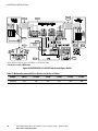
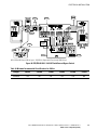
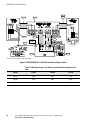
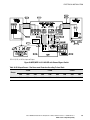


Transcript
Powerware Series ® ® Eaton FERRUPS Rack Mount UPS Installation Guide Class A EMC Statements FCC Part 15 NOTE This equipment has been tested and found to comply with the limits for a Class A digital device, pursuant to part 15 of the FCC Rules. These limits are designed to provide reasonable protection against harmful interference when the equipment is operated in a commercial environment. This equipment generates, uses, and can radiate radio frequency energy and, if not installed and used in accordance with the instruction manual, may cause harmful interference to radio communications. Operation of this equipment in a residential area is likely to cause harmful interference in which case the user will be required to correct the interference at his own expense. ICES-003 This Class A Interference Causing Equipment meets all requirements of the Canadian Interference Causing Equipment Regulations ICES‐003. Cet appareil numérique de la classe A respecte toutes les exigences du Reglement sur le matériel brouilleur du Canada. For Users in Germany We hereby certify that the uninterruptible power system (QFES 850 VA, 1.15 kVA, 1.4 kVA, 1.8 kVA, 2.1 kVA, and 3.1 kVA; QFER 1.8 kVA, 2.1 kVA, 3.1 kVA, 4.3 kVA, and 7 kVA) complies with the RFI suppression requirements of Vfg. 243/1991 and Vfg. 46/1992. The German Postal Service was notified that the equipment is being marketed. The German Postal Service has the right to retest the equipment and verify compliance. Hiermit wird bescheinigt, daß die unterbrechungsfreie Stromversorgung (QFES 850 VA, 1.15 kVA, 1.4 kVA, 1.8 kVA, 2.1 kVA, and 3.1 kVA; QFER 1.8 kVA, 2.1 kVA, 3.1 kVA, 4.3 kVA, and 7 kVA) in Übereinstimmung mit den Bestimmungen der Vfg. 243/1991 und Vfg. 46/1992 funkentstört ist. Der Deutschen Bundespost wurde das Inverkehrbringen dieses Gerätes angezeigt und die Berechtigung zur Überprüfung der Serie auf Einhaltung der Bestimmung eingeräumt. aton reserves the right to change specifications without prior notice. Eaton, Powerware, and FERRUPS are registered trademarks of Eaton Corporation or its subsidiaries and affiliates. All other trademarks are property of their respective companies. ECopyright 1996–2010 Eaton Corporation, Raleigh, NC, USA. All rights reserved. No part of this document may be reproduced in any way without the express written approval of aton. Table of Contents 1 Introduction . . . . . . . . . . . . . . . . . . . . . . . . . . . . . . . . . . . . . . . . . . . . . . . . . . . . . . . . . 1 Plug-Receptacle Installation . . . . . . . . . . . . . . . . . . . . . . . . . . . . . . . . . . . . . . . . . . . . . . . . . . . . . . . . . . . . . Hardwired Installation . . . . . . . . . . . . . . . . . . . . . . . . . . . . . . . . . . . . . . . . . . . . . . . . . . . . . . . . . . . . . . . . . 1 1 2 Safety Warnings . . . . . . . . . . . . . . . . . . . . . . . . . . . . . . . . . . . . . . . . . . . . . . . . . . . . . 3 3 Setup . . . . . . . . . . . . . . . . . . . . . . . . . . . . . . . . . . . . . . . . . . . . . . . . . . . . . . . . . . . . . . 17 Dimensions . . . . . . . . . . . . . . . . . . . . . . . . . . . . . . . . . . . . . . . . . . . . . . . . . . . . . . . . . . . . . . . . . . . . . . . . . Location Requirements . . . . . . . . . . . . . . . . . . . . . . . . . . . . . . . . . . . . . . . . . . . . . . . . . . . . . . . . . . . . . . . . . Storage and Operating Environment . . . . . . . . . . . . . . . . . . . . . . . . . . . . . . . . . . . . . . . . . . . . . . . . . . . . . . . 17 19 20 Battery Cabinet Installation . . . . . . . . . . . . . . . . . . . . . . . . . . . . . . . . . . . . . . . . . . . . 21 Before Installing the Batteries . . . . . . . . . . . . . . . . . . . . . . . . . . . . . . . . . . . . . . . . . . . . . . . . . . . . . . . . . . . Required Tools . . . . . . . . . . . . . . . . . . . . . . . . . . . . . . . . . . . . . . . . . . . . . . . . . . . . . . . . . . . . . . . . . . . . Electrical . . . . . . . . . . . . . . . . . . . . . . . . . . . . . . . . . . . . . . . . . . . . . . . . . . . . . . . . . . . . . . . . . . . . . . . . Identifying the Batteries . . . . . . . . . . . . . . . . . . . . . . . . . . . . . . . . . . . . . . . . . . . . . . . . . . . . . . . . . . . . . . . . Installing RBC-1 or RBC-2 Battery Cabinets . . . . . . . . . . . . . . . . . . . . . . . . . . . . . . . . . . . . . . . . . . . . . . . . . . Installing the Batteries in RBC-1 or RBC-2 Battery Cabinets . . . . . . . . . . . . . . . . . . . . . . . . . . . . . . . . . . . . Installing the RBC-3 Battery Cabinet . . . . . . . . . . . . . . . . . . . . . . . . . . . . . . . . . . . . . . . . . . . . . . . . . . . . . . . RBC-3 Battery Cabinet DC Connections . . . . . . . . . . . . . . . . . . . . . . . . . . . . . . . . . . . . . . . . . . . . . . . . . . . 22 22 23 24 25 31 33 39 5 UPS Cabinet Installation . . . . . . . . . . . . . . . . . . . . . . . . . . . . . . . . . . . . . . . . . . . . . . . 43 6 Electrical Installation . . . . . . . . . . . . . . . . . . . . . . . . . . . . . . . . . . . . . . . . . . . . . . . . . 49 Bypass Switches . . . . . . . . . . . . . . . . . . . . . . . . . . . . . . . . . . . . . . . . . . . . . . . . . . . . . . . . . . . . . . . . . . . . . Hardwiring the UPS and External Bypass Switch . . . . . . . . . . . . . . . . . . . . . . . . . . . . . . . . . . . . . . . . . . . . . . . Installation Wiring Diagrams for External Bypass Switches . . . . . . . . . . . . . . . . . . . . . . . . . . . . . . . . . . . . . . . 49 51 57 Battery Wiring . . . . . . . . . . . . . . . . . . . . . . . . . . . . . . . . . . . . . . . . . . . . . . . . . . . . . . . 69 RBC-1 or RBC-2 DC Wiring . . . . . . . . . . . . . . . . . . . . . . . . . . . . . . . . . . . . . . . . . . . . . . . . . . . . . . . . . . . . . . RBC-3 DC Wiring . . . . . . . . . . . . . . . . . . . . . . . . . . . . . . . . . . . . . . . . . . . . . . . . . . . . . . . . . . . . . . . . . . . . . Replacing the Batteries . . . . . . . . . . . . . . . . . . . . . . . . . . . . . . . . . . . . . . . . . . . . . . . . . . . . . . . . . . . . . . . . Recycling the Used Battery . . . . . . . . . . . . . . . . . . . . . . . . . . . . . . . . . . . . . . . . . . . . . . . . . . . . . . . . . . . . . . 70 72 72 74 Phase Check . . . . . . . . . . . . . . . . . . . . . . . . . . . . . . . . . . . . . . . . . . . . . . . . . . . . . . . . 75 4 7 8 Eaton FERRUPS Rack Mount UPS (850 VA–7 kVA) Installation Guide S 164201425 Rev 1 www.eaton.com/powerquality i TABLE OF CONTENTS ii Eaton FERRUPS Rack Mount UPS (850 VA–7 kVA) Installation Guide S 164201425 Rev 1 www.eaton.com/powerquality Chapter 1 Introduction The Eaton® FERRUPS® Rack Mount uninterruptible power system (UPS) is available in plug-receptacle or hardwired models. The plug-receptacle models have an input plug and receptacles on the rear panel. The hardwired models have terminal strips that an electrician has to wire to AC input. See the following sections for steps on how to use this manual for your UPS installation. Plug-Receptacle Installation Only a few sections in this manual are required for installing plug-receptacle models: S Be sure to read all safety warnings before installing the UPS as stated in Chapter 2, “Safety Warnings.” S Complete Chapter 3, “Setup” for setting up the location of the UPS. S If you purchased an external battery cabinet, an electrician must install the battery cabinets as described in Chapter 4, “Battery Cabinet Installation.” S Install the UPS cabinet as described in Chapter 5, “UPS Cabinet Installation.” S If you purchased an external battery cabinet, an electrician must complete the DC wiring as described in Chapter 7, “Battery Wiring.” S Continue to the startup section in the Eaton FERRUPS Rack Mount UPS (850 VA–7 kVA) User's Guide. Hardwired Installation Most of the sections in this manual are required for the electrician to install the hardwired models: S Be sure to read all safety warnings before installing the UPS as stated in Chapter 2, “Safety Warnings.” S Complete Chapter 3, “Setup” for setting up the location of the UPS. Eaton FERRUPS Rack Mount UPS (850 VA–7 kVA) Installation Guide S 164201425 Rev 1 www.eaton.com/powerquality 1 INTRODUCTION S If you purchased an external battery cabinet, an electrician must install the battery cabinets as described in Chapter 4, “Battery Cabinet Installation.” S Install the UPS cabinet as described in Chapter 5, “UPS Cabinet Installation.” S Chapter 6, “Electrical Installation” describes the electrical requirements for hardwiring the UPS and external bypass switch. S If you purchased an external battery cabinet, an electrician must complete the DC wiring as described in Chapter 7, “Battery Wiring.” S Complete the phase check as described in Chapter 8, “Phase Check.” S Continue to the startup section in the Eaton FERRUPS Rack Mount UPS (850 VA–7 kVA) User's Guide. 2 Eaton FERRUPS Rack Mount UPS (850 VA–7 kVA) Installation Guide S 164201425 Rev 1 www.eaton.com/powerquality Chapter 2 Safety Warnings IMPORTANT SAFETY INSTRUCTIONS SAVE THESE INSTRUCTIONS This manual contains important instructions that you should follow during installation and maintenance of the UPS and batteries. Please read all instructions before operating the equipment and save this manual for future reference. DANGER This UPS contains LETHAL VOLTAGES. All repairs and service should be performed by AUTHORIZED SERVICE PERSONNEL ONLY. There are NO USER SERVICEABLE PARTS inside the UPS. WARNING S This UPS contains its own energy source (batteries). The output receptacles may carry live voltage even when the UPS is not connected to an AC supply. S Do not remove or unplug the input cord when the UPS is turned on. This removes the safety ground from the UPS and the equipment connected to the UPS. S To reduce the risk of fire or electric shock, install this UPS in a temperature and humidity controlled, indoor environment, free of conductive contaminants. Ambient temperature must not exceed 40°C (104°F). Do not operate near water or excessive humidity (95% max). S To comply with international standards and wiring regulations, the total equipment connected to the output of this UPS must not have an earth leakage current greater than 1.5 milliamperes. CAUTION S Batteries can present a risk of electrical shock or burn from high short-circuit current. Observe proper precautions. Servicing should be performed by qualified service personnel knowledgeable of batteries and required precautions. Keep unauthorized personnel away from batteries. S Proper disposal of batteries is required. Refer to your local codes for disposal requirements. S Never dispose of batteries in a fire. Batteries may explode when exposed to flame. Eaton FERRUPS Rack Mount UPS (850 VA–7 kVA) Installation Guide S 164201425 Rev 1 www.eaton.com/powerquality 3 SAFETY WARNINGS Sikkerhedsanvisninger VIGTIGE SIKKERHEDSANVISNINGER GEM DISSE ANVISNINGER Denne manual indeholder vigtige instruktioner, som skal følges under installation og vedligeholdelse af UPS'en og batterierne. Læs venligst alle instruktioner inden betjening af udstyret og gem denne manual mhp. fremtidige opslag. FARE Denne UPS indeholder LIVSFARLIG HØJSPÆNDING. Alle reparationer og vedligeholdelse bør kun udføres af en AUTORISERET SERVICETEKNIKER. Ingen af UPS'ens indvendige dele kan repareres af brugeren. ADVARSEL! S Denne UPS indeholder egen energiforsyning (batterier). Udgangsnetstikkene kan lede strøm, selv når UPS'en ikke er tilsat en AC-energikilde. S Netledningen må ikke fjernes og stikket må ikke trækkes ud, mens UPS'en er tændt. Dette fjerner sikkerhedsjorden fra UPS'en og fra det udstyr, der er sat til. S Installér denne UPS i et temperatur- og fugtighedskontrolleret indendørsmiljø, frit for ledende forureningsstoffer for at formindske risikoen for brand og elektrisk stød. Rumtemperaturen må ikke overstige 40°C. UPS'en bør ikke betjenes nær vand eller høj fugtighed (maksimalt 95%). S I overensstemmelse med internationale normer og bestemmelser for el-installation må det udstyr, der er forbundet til udgangen af denne UPS, tilsammen ikke overskride en jordafdelingsspænding på mere end 1,5 milliampere. ADVARSEL S Batterierne kan give risiko for elektrisk stød eller brandsår forårsaget af høj kortslutningsstrøm. Overhold gældende forsigtighedsregler. Servicering skal udføres af kvalificeret servicepersonale med kendskab til batterier og gældende forsigtighedsregler. Hold uautoriseret personale væk fra batterierne. S Korrekt bortskaffelse af batterier er påkrævet. Overhold gældende lokale regler for bortskaffelsesprocedurer. S Skaf dig aldrig af med batterierne ved at brænde dem. Batterierne kan eksplodere ved åben ild. 4 Eaton FERRUPS Rack Mount UPS (850 VA–7 kVA) Installation Guide S 164201425 Rev 1 www.eaton.com/powerquality SAFETY WARNINGS Belangrijke Veiligheidsinstructies BELANGRIJKE VEILIGHEIDSINSTRUCTIES BEWAAR DEZE INSTRUCTIES Deze handleiding bevat belangrijke instructies die u dient te volgen tijdens de installatie en het onderhoud van de UPS en de accu's. Lees alle instructies voordat u de apparatuur in bedrijf neemt en bewaar deze handleiding als naslagwerk. GEVAAR Deze UPS bevat LEVENSGEVAARLIJKE ELEKTRISCHE SPANNING. Alle reparaties en onderhoud dienen UITSLUITEND DOOR ERKEND SERVICEPERSONEEL te worden uitgevoerd. Er bevinden zich GEEN ONDERDELEN in de UPS die DOOR DE GEBRUIKER kunnen worden GEREPAREERD. WAARSCHUWING S Deze UPS bevat zijn eigen energiebron (batterijen). De uitgangsaansluitingen kunnen onder spanning staan wanneer de UPS niet op een wisselstroom voeding is aangesloten. S Verwijder de ingangsnoer niet of haal de stekker van de ingangsnoer er niet uit terwijl de UPS aan staat. Hierdoor zou de UPS en uw aangesloten apparatuur geen aardebeveiliging meer hebben. S Teneinde de kans op brand of elektrische schok te verminderen dient deze UPS in een gebouw met temperatuur‐ en vochtigheidregeling te worden geïnstalleerd, waar geen geleidende verontreinigingen aanwezig zijn. De omgevingstemperatuur mag 40°C niet overschrijden. Niet gebruiken in de buurt van water of bij zeer hoge vochtigheid (max. 95%). S Om aan de internationale normen en bedradingsvoorschriften te voldoen mag de gehele apparatuur die op de uitgang van deze UPS is aangesloten, geen aardlekstroom van meer dan 1,5 milliampère hebben. OPGELET S Batterijen leveren gevaar op voor elektrische schokken en kunnen brandwonden veroorzaken door een grote kortsluitstroom. Neem de juiste voorzorgsmaatregelen in acht. Het onderhoud moet worden uitgevoerd door bevoegde onderhoudsmonteurs die verstand hebben van accu's en op de hoogte zijn van de vereiste voorzorgsmaatregelen. Houd onbevoegden uit de buurt van de accu's. S De batterijen moeten op de juiste wijze worden opgeruimd. Raadpleeg hiervoor uw plaatselijke voorschriften. S Nooit batterijen in het vuur gooien. De batterijen kunnen ontploffen. Eaton FERRUPS Rack Mount UPS (850 VA–7 kVA) Installation Guide S 164201425 Rev 1 www.eaton.com/powerquality 5 SAFETY WARNINGS Tarkeita Turvaohjeita TÄRKEITÄ TURVAOHJEITA - SUOMI SÄILYTÄ NÄMÄ OHJEET Tämä käyttöohje sisältää tärkeitä ohjeita, joita on noudatettava UPS-virtalähteen ja akkujen asennuksen ja huollon yhteydessä. Lue kaikki ohjeet ennen laitteiston käyttöä ja säilytä ohje myöhempää tarvetta varten. VAARA Tämä UPS sisältää HENGENVAARALLISIA JÄNNITTEITÄ. Kaikki korjaukset ja huollot on jätettävä VAIN VALTUUTETUN HUOLTOHENKILÖN TOIMEKSI. UPS ei sisällä MITÄÄN KÄYTTÄJÄN HUOLLETTAVIA OSIA. VAROITUS S Tämä UPS sisältää oman energialähteen (akuston). Ulostuloliittimissä voi olla jännite, kun UPS ei ole liitettynä verkkojännitteeseen. S Älä poista tai irrota sisääntulojohtoa, kun UPS on kytkettynä. Tämä poistaa turvamaadoituksen UPS-laitteesta ja siihen liitetystä laitteistosta. S Vähentääksesi tulipalon ja sähköiskun vaaraa asenna tämä UPS sisätiloihin, joissa lämpötila ja kosteus on säädettävissä ja joissa ei ole virtaa johtavia epäpuhtauksia. Ympäristön lämpötila ei saa ylittää 40 °C. Älä käytä lähellä vettä ja vältä kosteita tiloja (95 % maksimi). S Kansainväliset normit ja johdotusmääräykset vaativat, että kaikkien tämän UPS-laitteen ulostulokytkentöjen yhteinen maavuotovirta ei ylitä 1,5 milliampeeria (mA). VARO S Akut voivat aiheuttaa sähköiskun tai palovammojen vaaran johtuen suuresta oikosulkuvirrasta. Noudata kaikkia asianmukaisia varotoimia. Laitteen saa huoltaa vain ammattitaitoinen huoltohenkilökunta, joka tuntee akut ja niihin liittyvät varotoimet. Älä päästä valtuuttamatonta henkilöstöä lähelle akkuja. S Akusto täytyy hävittää säädösten mukaisella tavalla. Noudata paikallisia määräyksiä. S Älä koskaan heitä akkuja tuleen. Ne voivat räjähtää. 6 Eaton FERRUPS Rack Mount UPS (850 VA–7 kVA) Installation Guide S 164201425 Rev 1 www.eaton.com/powerquality SAFETY WARNINGS Consignes de sécurité CONSIGNES DE SÉCURITÉ IMPORTANTES CONSERVER CES INSTRUCTIONS Ce manuel comporte des instructions importantes que vous êtes invité à suivre lors de toute procédure d'installation et de maintenance des batteries et de l'onduleur. Veuillez consulter entièrement ces instructions avant de faire fonctionner l'équipement et conserver ce manuel afin de pouvoir vous y reporter ultérieurement. DANGER! Cet onduleur contient des TENSIONS MORTELLES. Toute opération d'entretien et de réparation doit être EXCLUSIVEMENT CONFIÉE A UN PERSONNEL QUALIFIÉ AGRÉÉ. AUCUNE PIÈCE RÉPARABLE PAR L'UTILISATEUR ne se trouve dans l'onduleur. AVERTISSEMENT! S Cet onduleur renferme sa propre source d'énergie (batteries). Les prises de sortie peuvent être sous tension même lorsque l'onduleur n'est pas branché sur le secteur. S Ne pas retirer le cordon d'alimentation lorsque l'onduleur est sous tension sous peine de supprimer la mise à la terre de l'onduleur et du matériel connecté. S Pour réduire les risques d'incendie et de décharge électrique, installer l'onduleur uniquement à l'intérieur, dans un lieu dépourvu de matériaux conducteurs, où la température et l'humidité ambiantes sont contrôlées. La température ambiante ne doit pas dépasser 40 °C. Ne pas utiliser à proximité d'eau ou dans une atmosphère excessivement humide (95 % maximum). S Afin d'être conforme aux normes et règlements internationaux de câblage, le courant de fuite à la terre de la totalité du matériel branché sur la sortie de l'onduleur ne doit pas dépasser 1,5 mA. ATTENTION! S Les batteries peuvent présenter un risque de choc électrique ou de brûlure provenant d'un courant de court-circuit haute intensité. Observez les précautions appropriées. L'entretien doit être réalisé par du personnel qualifié connaissant bien les batteries et les précautions nécessaires. N'autorisez aucun personnel non qualifié à manipuler les batteries. S Une mise au rebut réglementaire des batteries est obligatoire. Consulter les règlements en vigueur dans votre localité. S Ne jamais jeter les batteries au feu. L'exposition aux flammes risque de les faire exploser. Eaton FERRUPS Rack Mount UPS (850 VA–7 kVA) Installation Guide S 164201425 Rev 1 www.eaton.com/powerquality 7 SAFETY WARNINGS Sicherheitswarnungen WICHTIGE SICHERHEITSANWEISUNGEN AUFBEWAREN Dieses Handbuch enthält wichtige Anweisungen, die Sie während der Installation und Wartung des USV (Unterbrechungsfreies Stromversorgungssystem) und der Batterien befolgen müssen. Bitte lesen Sie alle Anweisungen des Handbuches bevor sie mit dem Gerät arbeiten. Bewaren Sie das Handbuch zum Nachlesen auf. WARNUNG Die USV führt lebensgefährliche Spannungen. Alle Reparatur- und Wartungsarbeiten sollten nur von Kundendienstfachleuten durchgeführt werden. Die USV enthält keine vom Benutzer zu wartenden Komponenten. ACHTUNG S Diese USV ist mit einer eigenen Energiequelle (Batterie) ausgestattet. An den Ausgangssteckdosen kann auch dann Spannung anliegen, wenn die USV nicht an einer Wechselspannungsquelle angeschlossen ist. S Das Eingangskabel nicht entfernen oder abziehen, während die USV eingeschaltet ist, weil hierdurch die Sicherheitserdung von der USV und den daran angeschlossenen Geräten entfernt wird. S Um die Brand‐ oder Elektroschockgefahr zu verringern, diese USV nur in Gebäuden mit kontrollierter Temperatur und Luftfeuchtigkeit installieren, in denen keine leitenden Schmutzstoffen vorhanden sind. Die Umgebungstemperatur darf 40°C nicht übersteigen. Die USV nicht in der Nähe von Wasser oder in extrem hoher Luftfeuchtigkeit (max. 95 %) betreiben. S Um internationale Normen und Verdrahtungsvorschriften zu erfüllen, dürfen die an den Ausgang dieser USV angeschlossenen Geräte zusammen einen Erdschlußstrom von insgesamt 1,5 Milliampere nicht überschreiten. VORSICHT! S Batterien können das Risiko eines elektrischen Schlags bergen oder durch hohen Kurzschlussstrom in Brand geraten. Die richtigen Vorsichtsmaßnahmen beachten. Die Wartung muss von qualifiziertem Wartungspersonal durchgeführt werden, das im Umgang mit Batterien geübt ist und über gute Kenntnisse der erforderlichen Vorsichtsmaßnahmen verfügt. Nicht autorisiertes Personal von Batterien fern halten. S Die Batterien müssen ordnungsgemäß entsorgt werden. Hierbei sind die örtlichen Bestimmungen zu beachten. S Batterien niemals verbrennen, da sie explodieren können. 8 Eaton FERRUPS Rack Mount UPS (850 VA–7 kVA) Installation Guide S 164201425 Rev 1 www.eaton.com/powerquality SAFETY WARNINGS !" #$ % & '()*+%' ,* ) &-&*. +' &'*'/'* .' '(% &) %&'* '&*.')'* & / ! S #0 ! 1" !#" # 234 01 51 0 $ # 6! 0! 1 $ 110 !#" 0 70 2894 S %! :#6; ! $; <1 =1$ $ %> =$ ! #$3! =$ 5 0 $ 110 0 S , 0< $1 #6 " ! !5$? #" #0 3 < 0 #0! @0$ #$? $ 0! #<#0 6 @0$ :6 1 5 6 AB°C9 %! !0 $ 6 " :" #$ 20#! 0"D EFG4 S , 0=3$ 0 1@" 07 31$3!? 70 1" ! #! ! 5 07? $ 110 0 ! 51 #0 ? 1 $ 0#7 H?F I8 !" S 3 0 $ ! !5$ " #0 J! 70 :<0 K0:6 6! =65 S $ 3" 16@! 3 3< +$ 7 07 =7 " 16@" S & 0! 6 3 ! =36? #$ 0 $ #7 Eaton FERRUPS Rack Mount UPS (850 VA–7 kVA) Installation Guide S 164201425 Rev 1 www.eaton.com/powerquality 9 SAFETY WARNINGS Avvisi di sicurezza IMPORTANTI ISTRUZIONI DI SICUREZZA CONSERVARE QUESTE ISTRUZIONI Il presente manuale contiene importanti istruzioni da seguire durante l'installazione e la manutenzione dell'UPS e delle batterie. Leggere integralmente le istruzioni prima di utilizzare l'apparecchiatura e conservare il presente manuale per futuro riferimento. PERICOLO La TENSIONE contenuta in questo gruppo statico di continuità è LETALE. Tutte le operazioni di riparazione e di manutenzione devono essere effettuate ESCLUSIVAMENTE DA PERSONALE TECNICO AUTORIZZATO. All'interno del gruppo statico di continuità NON vi sono PARTI RIPARABILI DALL'UTENTE. AVVERTENZA S Questo gruppo statico di continuità contiene una fonte di energia autonoma (le batterie). Le prese di uscita possono condurre tensione energizzata quando il gruppo statico di continuità non è collegato con una fonte di alimentazione a corrente alternata. S Non rimuovere nè scollegare il cavo di ingresso quando il gruppo statico di continuità è acceso poichè in tal modo si disattiverebbe il collegamento a terra di sicurezza del gruppo statico di continuità e dell'apparecchiatura ad esso collegata. S Per ridurre il rischio di incendio o di scossa elettrica, installare il gruppo statico di continuità in un ambiente interno a temperatura ed umidità controllata, privo di agenti contaminanti conduttivi. La temperatura ambiente non deve superare i 40°C. Non utilizzare l'unità in prossimità di acqua o in presenza di umidità eccessiva (95% max). S Per conformità con gli standard internazionali e con le norme in merito al cablaggio, tutta l'apparecchiatura collegata con l'uscita del gruppo statico di continuità non deve avere una corrente di dispersione di terra superiore a 1,5 milliampere. ATTENZIONE S Le batterie possono comportare un rischio di scossa elettrica o di ustione in seguito a un'elevata corrente di corto circuito. Osservare le dovute precauzioni. L'assistenza deve essere eseguita da personale qualificato esperto di batterie e delle necessarie precauzioni. Tenere il personale non autorizzato lontano dalle batterie. S Le batterie devono essere smaltite in modo corretto. Per i requisiti di smaltimento fare riferimento alle disposizioni locali. S Non gettare mai le batterie nel fuoco poichè potrebbero esplodere se esposte alle fiamme. 10 Eaton FERRUPS Rack Mount UPS (850 VA–7 kVA) Installation Guide S 164201425 Rev 1 www.eaton.com/powerquality SAFETY WARNINGS Viktig Sikkerhetsinformasion VIKTIGE SIKKERHETSINSTRUKSJONER GJEM DISSE INSTRUKSJONENE Denne håndboken inneholder viktige instruksjoner som du bør overholde ved montering og vedlikehold av UPS-enheten og batteriene. Les alle instruksjoner før utstyret tas i bruk, og gjem håndboken til fremtidig referanse. FARLIG Denne UPS'en inneholder LIVSFARLIGE SPENNINGER. All reparasjon og service må kun utføres av AUTORISERT SERVICEPERSONALE. BRUKERE KAN IKKE UTFØRE SERVICE PÅ NOEN AV DELENE i UPS'en. FARLIG S Denne UPS'en har en egen energikilde (batterier). Stikkontaktene kan være strømførende selv om UPS'en ikke er tilsluttet en vekselstrømforsyning. S Strømforsyningskabelen må ikke fjernes eller trekkes ut når UPS'en er på, slik at ikke sikkerhetsjordingen fjernes fra UPS'en og det utstyret som er forbundet med den. S For å redusere fare for brann eller elektriske støt, bør denne UPS'en installeres i et innendørs miljø med kontrollert temperatur og luftfuktighet som er fritt for ledende, forurensende stoffer. Romtemperaturen må ikke overskride 40°C. Den må ikke brukes i nærheten av vann eller ved meget høy luftfuktighet (95% maks.). S Alt utstyr som er forbundet med utgangen av denne UPS'en må ikke ha en sterkere total lekkasjestrøm enn 1,5 milliampere for å være i overensstemmelse med internasjonale standarder og forkablingsbestemmelser. FORSIKTIG S Batterier kan utgjøre en fare for elektrisk støt eller brannsår pga. høy kortsluttingsstrøm. Treff passende forholdsregler. Service bør utføres av kvalifisert servicepersonale med kjennskap til batterier og nødvendige forholdsregler. Hold uautorisert personale borte fra batteriene. S Batterier må fjernes på korrekt måte. Se lokale forskrifter vedrørende krav om fjerning av batterier. S Kast aldri batterier i flammer, da de kan eksplodere, hvis de utsettes for åpen ild. Eaton FERRUPS Rack Mount UPS (850 VA–7 kVA) Installation Guide S 164201425 Rev 1 www.eaton.com/powerquality 11 SAFETY WARNINGS Regulamentos de Segurança INSTRUÇÕES DE SEGURANÇA IMPORTANTES GUARDE ESTAS INSTRUÇÕES Este manual contém instruções importantes que devem ser seguidas durante a instalação e manutenção do no-break e das baterias. Leia todas as instruções antes de operar o equipamento e guarde este manual para consultá-lo futuramente. CUIDADO A UPS contém VOLTAGEM MORTAL. Todos os reparos e assistência técnica devem ser executados SOMENTE POR PESSOAL DA ASSISTÊNCIA TÉCNICA AUTORIZADO. Não há nenhuma PEÇA QUE POSSA SER REPARADA PELO USUÁRIO dentro da UPS. ADVERTÊNCIA S Esta UPS contém sua própria fonte de energia (baterias). Os receptáculos de saída podem conter voltagem ativa quando a UPS não se encontra conectada a uma fonte de alimentação de corrente alternada. S Não remova ou desconecte o cabo de entrada quando a UPS estiver ligada. Isto removerá o aterramento de segurança da UPS e do equipamento conectado. S Para reduzir o risco de incêndios ou choques elétricos, instale a UPS em ambiente interno com temperatura e umidade controladas e livres de contaminadores condutíveis. A temperatura ambiente não deve exceder 40°C. Não opere próximo a água ou em umidade excessiva (máx: 95%). S Para estar de acordo com os padrões internacionais e os regulamentos de fiação, o equipamento total conectado à saída desta UPS não deve ter uma corrente de fuga à terra maior que 1,5 miliampères. PERIGO S As baterias podem oferecer risco de choque elétrico ou queimadura, ocasionados por alta tensão com possibilidade de curto-circuito. Tome as precauções adequadas. A manutenção deve ser realizada por pessoal qualificado, com conhecimento sobre baterias e ciente das precauções exigidas. Mantenha o pessoal não autorizado afastado das baterias. S Siga as instruções apropriadas ao desfazer‐se das baterias. Consulte os códigos do local para maiores informações sobre os regulamentos de descarte de produtos. S Nunca jogue as baterias no fogo, porque há risco de explosão. 12 Eaton FERRUPS Rack Mount UPS (850 VA–7 kVA) Installation Guide S 164201425 Rev 1 www.eaton.com/powerquality SAFETY WARNINGS Ïðåäóïðåæäåíèÿ ïî ìåðàì áåçîïàñíîñòè ÂÀÆÍÛÅ ÓÊÀÇÀÍÈß ÏÎ ÌÅÐÀÌ ÁÅÇÎÏÀÑÍÎÑÒÈ ÑÎÕÐÀÍÈÒÅ ÝÒÈ ÓÊÀÇÀÍÈß Â äàííîì ðóêîâîäñòâå ñîäåðæàòñÿ âàæíûå èíñòðóêöèè ïî óñòàíîâêå è îáñëóæèâàíèþ èñòî÷íèêà áåñïåðåáîéíîãî ïèòàíèÿ (ÈÁÏ) è áàòàðåé. Ïåðåä ðàáîòîé ñ îáîðóäîâàíèåì ïðî÷òèòå âñå èíñòðóêöèè. Ñîõðàíèòå äàííîå ðóêîâîäñòâî äëÿ äàëüíåéøåãî èñïîëüçîâàíèÿ. ÎÏÀÑÍÎ Â äàííîì ÈÁÏ èìåþòñÿ ÑÌÅÐÒÅËÜÍÎ ÎÏÀÑÍÛÅ ÍÀÏÐßÆÅÍÈß. Âñå ðàáîòû ïî ðåìîíòó è îáñëóæèâàíèþ äîëæíû âûïîëíÿòüñÿ ÒÎËÜÊÎ ÓÏÎËÍÎÌÎ×ÅÍÍÛÌ ÎÁÑËÓÆÈÂÀÞÙÈÌ ÏÅÐÑÎÍÀËÎÌ. Âíóòðè ÈÁÏ íåò óçëîâ, ÎÁÑËÓÆÈÂÀÅÌÛÕ ÏÎËÜÇÎÂÀÒÅËÅÌ. ÏÐÅÄÓÏÐÅÆÄÅÍÈÅ S Äàííûé ÈÁÏ ñîäåðæèò ñîáñòâåííûå èñòî÷íèêè ýíåðãèè (àêêóìóëÿòîðû). Íà âûõîäíûõ ðîçåòêàõ ìîæåò èìåòüñÿ íàïðÿæåíèå, äàæå êîãäà ÈÁÏ íå ïîäêëþ÷åí ê ñåòè ïåðåìåííîãî òîêà. S Íå îòñîåäèíÿéòå ñåòåâîé øíóð è íå èçâëåêàéòå åãî âèëêó èç ðîçåòêè ïðè âêëþ÷åííîì ÈÁÏ. Ïðè ýòîì çàùèòíîå çàçåìëåíèå îòêëþ÷àåòñÿ îò ÈÁÏ è îò îáîðóäîâàíèÿ, ïîäêëþ÷åííîãî ê ÈÏÁ. S Äëÿ ñíèæåíèÿ îïàñíîñòè ïîæàðà èëè ïîðàæåíèÿ ýëåêòðè÷åñêèì òîêîì óñòàíàâëèâàéòå ÈÁÏ â çàêðûòîì ïîìåùåíèè ñ êîíòðîëèðóåìûìè òåìïåðàòóðîé è âëàæíîñòüþ, â êîòîðîì îòñóòñòâóþò ïðîâîäÿùèå çàãðÿçíÿþùèå âåùåñòâà. Òåìïåðàòóðà îêðóæàþùåãî âîçäóõà íå äîëæíà ïðåâûøàòü 40°Ñ. Íå ýêñïëóàòèðóéòå óñòðîéñòâî îêîëî âîäû èëè â ìåñòàõ ñ ïîâûøåííîé âëàæíîñòüþ (ìàêñ. 95%). S Äëÿ îáåñïå÷åíèÿ ñîáëþäåíèÿ òðåáîâàíèé ìåæäóíàðîäíûõ ñòàíäàðòîâ è òðåáîâàíèé ê ðàçâîäêå ýëåêòðè÷åñêèõ öåïåé, ñóììàðíàÿ âåëè÷èíà òîêà óòå÷êè íà çåìëþ âñåãî îáîðóäîâàíèÿ, ïîäêëþ÷åííîãî ê âûõîäó ÈÁÏ, íå äîëæíà ïðåâûøàòü 1,5 ìèëëèàìïåðà. ÎÑÒÎÐÎÆÍÎ S Âûñîêîå íàïðÿæåíèå, âûçâàííîå êîðîòêèì çàìûêàíèåì â áàòàðåå, ìîæåò ïðèâåñòè ê ïîðàæåíèþ ýëåêòðè÷åñêèì òîêîì èëè îæîãó. Ñîáëþäàéòå ìåðû ïðåäîñòîðîæíîñòè. Òåõíè÷åñêîå îáñëóæèâàíèå äîëæíî îñóùåñòâëÿòüñÿ êâàëèôèöèðîâàííûì ïåðñîíàëîì ïî ðàáîòå ñ èñòî÷íèêàìè ïèòàíèÿ, çíàêîìûì ñ ìåðàìè ïðåäîñòîðîæíîñòè. Íå äîïóñêàéòå ê ðàáîòå ñ áàòàðåÿìè ïîñòîðîííèõ. Eaton FERRUPS Rack Mount UPS (850 VA–7 kVA) Installation Guide S 164201425 Rev 1 www.eaton.com/powerquality 13 SAFETY WARNINGS S Íåîáõîäèìî ñîáëþäàòü ïðàâèëà óòèëèçàöèè àêêóìóëÿòîðîâ. Îáðàòèòåñü ê ìåñòíûì íîðìàòèâíûì àêòàì çà èíôîðìàöèåé î òðåáîâàíèÿõ ê óòèëèçàöèè. S Íèêîãäà íå áðîñàéòå àêêóìóëÿòîðû â îãîíü. Àêêóìóëÿòîðû ìîãóò âçîðâàòüñÿ ïîä âîçäåéñòâèåì îãíÿ. Advertencias de Seguridad INSTRUCCIONES DE SEGURIDAD IMPORTANTES GUARDE ESTAS INSTRUCCIONES Este manual contiene instrucciones importantes que debe seguir durante la instalación y el mantenimiento del SIE y de las baterías. Por favor, lea todas las instrucciones antes de poner en funcionamiento el equipo y guarde este manual para referencia en el futuro. PELIGRO Este SIE contiene VOLTAJES MORTALES. Todas las reparaciones y el servicio técnico deben ser efectuados SOLAMENTE POR PERSONAL DE SERVICIO TÉCNICO AUTORIZADO. No hay NINGUNA PARTE QUE EL USUARIO PUEDA REPARAR dentro del SIE. ADVERTENCIA S Este SIE contiene su propia fuente de energía (las baterías). Los receptáculos de salida pueden transmitir corriente eléctrica aun cuando el SIE no esté conectado a un suministro de corriente alterna (c.a.). S No retire o desenchufe el cable de entrada mientras el SIE se encuentre encendido. Esto suprime la descarga a tierra de seguridad del SIE y de los equipos conectados al SIE. S Para reducir el riesgo de incendio o de choque eléctrico, instale este SIE en un lugar cubierto, con temperatura y humedad controladas, libre de contaminantes conductores. La temperatura ambiente no debe exceder los 40°C. No trabaje cerca del agua o con humedad excesiva (95% máximo). S Para cumplir con los estándares internacionales y las normas de instalación, la totalidad de los equipos conectados a la salida de este SIE no debe tener una intensidad de pérdida a tierra superior a los 1,5 miliamperios. 14 Eaton FERRUPS Rack Mount UPS (850 VA–7 kVA) Installation Guide S 164201425 Rev 1 www.eaton.com/powerquality SAFETY WARNINGS PRECAUCIÓN S Las baterías pueden constituir un riesgo de descarga eléctrica o quemaduras por corriente alta de corto circuito. Adopte las precauciones debidas. Personal calificado de servicio que conozca de baterías y esté al tanto de las precauciones requeridas debe darle servicio al equipo. Mantenga al personal no autorizado alejado de las baterías. S Es necesario desechar las baterías de un modo adecuado. Consulte las normas locales para conocer los requisitos pertinentes. S Nunca deseche las baterías en el fuego. Las baterías pueden explotar si se las expone a la llama. Säkerhetsföreskrifter VIKTIGA SÄKERHETSFÖRESKRIFTER SPARA DESSA FÖRESKRIFTER Den här anvisningen innehåller viktiga instruktioner som du ska följa under installation och underhåll av UPS-enheten och batterierna. Läs alla instruktioner innan du använder utrustningen och spara den här anvisningen för framtida referens. FARA Denna UPS-enhet innehåller LIVSFARLIG SPÄNNING. ENDAST AUKTORISERAD SERVICEPERSONAL får utföra reparationer eller service. Det finns inga delar som ANVÄNDAREN KAN UTFÖRA SERVICE PÅ inuti UPS-enheten. VARNING S Denna UPS-enhet har en egen energikälla (batterier). De utgående kontakterna kan vara strömförande när UPS-enheten inte är ansluten till en växelströmkälla. S Ta aldrig bort nätsladden när UPS-enheten är påslagen. Detta tar bort skyddsjordningen från både UPS-enheten och den anslutna utrustningen. S Minska risken för brand eller elektriska stötar genom att installera denna UPS-enhet inomhus, där temperatur och luftfuktighet är kontrollerade och där inga ledande föroreningar förekommer. Omgivande temperatur får ej överstiga 40°C. Använd inte utrustningen nära vatten eller vid hög luftfuktighet (max 95 %). S För att överensstämma med internationell standard och installationsföreskrifter får inte den totala utrustning som anslutits till uttagen på denna UPS-enhet ha läcksström som överstiger 1,5 milliampere. Eaton FERRUPS Rack Mount UPS (850 VA–7 kVA) Installation Guide S 164201425 Rev 1 www.eaton.com/powerquality 15 SAFETY WARNINGS VIKTIGT S Batterierna kan innebära en risk för elektrisk stöt eller brännskada från kortsluten starkström. Iakttag lämpliga försiktighetsåtgärder. Service ska utföras av utbildad servicepersonal med kunskap om batterierna och nödvändiga försiktighetsåtgärder. Håll ej behörig personal borta från batterierna. S Batterierna måste avyttras enligt anvisningarna i lokal lagstiftning. S Använda batterier får aldrig brännas upp. De kan explodera. 16 Eaton FERRUPS Rack Mount UPS (850 VA–7 kVA) Installation Guide S 164201425 Rev 1 www.eaton.com/powerquality Chapter 3 Setup This chapter explains the requirements for setting up the UPS: S UPS, battery cabinet, and bypass switch dimensions S Location requirements S Storage and operating environment Dimensions Table 1. FERRUPS Rack Mount 850 VA–3.1 kVA Dimensions Dimensions (See Figure 1) UPS Model Height (A) Width (B) Depth (C) FES/QFES 850 VA, 1.15 kVA, 1.4 kVA, 1.8 kVA, 2.1 kVA, and 3.1 kVA 9.75I (24.8 cm) 16I (40.6 cm) 21.25I (54.0 cm) FER/QFER 1.8 kVA, 2.1 kVA, and 3.1 kVA 9.75I (24.8 cm) 16I (40.6 cm) 26.25I (66.7 cm) Front Panel 10.5I (26.7 cm) 19I (48.3 cm) – E B (FER) D (FES) A C F Figure 1. UPS Dimensions Eaton FERRUPS Rack Mount UPS (850 VA–7 kVA) Installation Guide S 164201425 Rev 1 www.eaton.com/powerquality 17 SETUP Table 2. FERRUPS Rack Mount 4.3 and 7 kVA Dimensions Dimensions (See Figure 1) UPS Model 4.3 kVA and 7 kVA Front Panel Height (D) Width (E) Depth (F) 19I (48.3 cm) 16I (40.6 cm) 26.25I (66.7 cm) 19.25I (48.9 cm) 19I (48.3 cm) – Table 3. Battery Cabinet Dimensions Dimensions (See Figure 2) Model Height (G) Width (H) Depth (I) RBC-1 and RBC-2 13.5I (34.3 cm) 17I (43.2 cm) 26.5I (67.3 cm) RBC-3 8.3I (21.1 cm) 16.25I (41.3 cm) 24.25I (61.6 cm) Front Panel 8.8I (22.4 cm) 19I (48.3 cm) – H G F Figure 2. Battery Cabinet Dimensions 18 Eaton FERRUPS Rack Mount UPS (850 VA–7 kVA) Installation Guide S 164201425 Rev 1 www.eaton.com/powerquality SETUP Table 4. External Bypass Switch Dimensions Dimensions (See Figure 3) Model A B C D E BPE-01 12I (30.5 cm) 6I (15.2 cm) 13I (33.0 cm) 10I (25.4 cm) 3I (7.6 cm) BPE-02 16I (40.6 cm) 8I (20.3 cm) 17I (43.2 cm) 12I (30.5 cm) 7I (17.8 cm) BPE-04 and BPE-05 17I (43.2 cm) 12I (30.5 cm) 18I (45.7 cm) 16I (40.6 cm) 9I (22.9 cm) B A E C E B A C D D BPE-01 BPE-02, 04, and 05 Figure 3. External Bypass Switch Dimensions Location Requirements Install the FERRUPS Rack Mount as close as possible to the equipment to be protected. If the UPS is more than 25 ft (7.6m) from the equipment, transient noise can reappear in the electrical distribution system. The UPS should be well ventilated and away from direct sunlight or other heat source. The environment can affect the reliability and performance of both the UPS and the batteries. Verify the storage and operating environmental requirements on page 20. If additional FERRUPS Rack Mount system batteries are in a separate external battery cabinet, the cabinet should be installed in the rack below the UPS. Eaton FERRUPS Rack Mount UPS (850 VA–7 kVA) Installation Guide S 164201425 Rev 1 www.eaton.com/powerquality 19 SETUP Storage and Operating Environment Storage Temperature: Store the batteries (in the UPS or external battery cabinet) at 20° to 40°C ( 4° to 104°F). Batteries will have a longer shelf life if they are kept below 25°C (77°F). The UPS or external battery cabinet without batteries may be stored at 20° to 60°C ( 4° to 140°F). - - - - Ventilation: The air around the UPS must be clean and free of dust, corrosive chemicals, and other contaminants. The air must be free to circulate around the UPS and battery cabinet(s). NOTE Do not place the UPS or batteries in a sealed room or container. Operating Temperature: The UPS can operate from 0° to 40°C (32° to 104°F). Do not operate near water or excessive humidity (95% max). For full battery life, keep the UPS at an ambient temperature of 25°C (77°F). High Altitude Operation: The maximum operating ambient temperature decreases 1°C per 300m above sea level (2°F per 1000 ft above sea level). Maximum elevation is 3000m (10,000 ft). 20 Eaton FERRUPS Rack Mount UPS (850 VA–7 kVA) Installation Guide S 164201425 Rev 1 www.eaton.com/powerquality Chapter 4 Battery Cabinet Installation WARNING Only qualified service personnel (such as a licensed electrician) should perform the electrical installation. Risk of electrical shock. CAUTION S Full voltage and current are always present at the battery terminals. The batteries used in this system can produce dangerous voltages, extremely high currents and a risk of electric shock. They may cause severe injury if the terminals are shorted together or to ground (earth). You must be extremely careful to avoid electric shock and burns caused by contacting battery terminals or shorting terminals during battery installation. Do not touch uninsulated battery terminals. S Any battery used with this UPS shall comply with the applicable requirements for batteries in the standard for emergency lighting and power equipment, UL 924. Cabinets are designed to be used with, and batteries must be replaced with, aton battery number BAT-XXXX or equivalent. S Never install the batteries in an air-tight enclosure. CAUTION The electrician must take these precautions: S Wear protective clothing and eye wear. For 120V battery systems, wear rubber gloves and boots. Batteries contain caustic acids and toxic materials and can rupture or leak if mistreated. Remove rings and metal wristwatches or other metal objects and jewelry. Don't carry metal objects in your pockets where the objects can fall into the battery cabinet. S Tools must have insulated handles and must be insulated so that they will not short battery terminals. Do not allow a tool to short a battery terminal to another battery terminal or to the cabinet at any time. Do not lay tools or metal parts on top of the batteries, and do not lay them where they could fall onto the batteries or into the cabinet. S Install the batteries as shown on the drawing provided with the batteries. When connecting cables, never allow a cable to short across a battery's terminals, the string of batteries, or to the cabinet. S Align the cables on the battery terminals so that the cable lug will not contact any part of the cabinet even if the battery is moved. Keep the cable away from any sharp metal edges. S Install the battery cables so they cannot be pinched by the battery cabinet or UPS doors. Eaton FERRUPS Rack Mount UPS (850 VA–7 kVA) Installation Guide S 164201425 Rev 1 www.eaton.com/powerquality 21 BATTERY CABINET INSTALLATION S Verify that the fuse is positioned so that it will not contact any cabinet parts or other battery posts if the batteries should move. Confirm that that there is enough clearance when the cabinet door closes. S Battery cabinet chassis (ground or earth) must be connected to the UPS chassis (ground or earth). If you use conduit, this ground conductor must be routed in the same conduit as the battery conductors. S Where conductors may be exposed to physical damage, protect the conductors in accordance with ANSI/NFPA 70-1993. S If you are replacing batteries or repairing battery connections, follow the procedure in the Eaton FERRUPS Rack Mount UPS (850 VA–7 kVA) User's Guide to shut off your UPS and remove both AC and DC input power. Before Installing the Batteries CAUTION Ensure that the floor is level and can support the weight of the UPS, batteries, rack, and any other necessary equipment. Refer to the Eaton FERRUPS Rack Mount UPS (850 VA–7 kVA) User's Guide for the UPS and battery weights. The battery cabinet or rack should be well ventilated and away from direct sunlight or other heat source. The temperature should be below 77°F (25°C) for the best battery performance. Batteries will be less efficient at temperatures below 65°F (18°C). High temperatures will reduce battery life. Typically, at about 95°F (35°C) battery life will be half of what it would be at a normal temperature of 77°F (25°C). At about 113°F (45°C), battery life will be one-fourth of normal. Required Tools The following items are required for battery installation. Use only tools with insulated handles: S Torque wrench calibrated in inch pounds or Newton meters S Petroleum jelly or conductive grease S Brush (to apply petroleum jelly or conductive grease to terminals) S Pliers S 9I extension S Ratchet 22 Eaton FERRUPS Rack Mount UPS (850 VA–7 kVA) Installation Guide S 164201425 Rev 1 www.eaton.com/powerquality BATTERY CABINET INSTALLATION S Standard and Phillips screwdrivers S Volt-ohm meter S Hammer S 7/16I socket wrench S Two 7/16I box-end thin-wall wrenches S Electrical tape Electrical Table 5. Nominal DC Battery Voltage Models Nominal Battery Voltage FES/QFES 850 VA–1.4 kVA 12 Vdc FES/QFES or FER/QFER 1.8–7 kVA 48 Vdc The battery cable or wire used is #1 AWG (42.11 mm2) for all applications with the following exception: S If the batteries must be some distance from the UPS, you may need to install larger battery cables between the battery cabinets and the UPS. Using long cable runs and larger diameter cables may require modifications inside the UPS; call your service representative if you did not order the longer, larger-diameter cable with the UPS. The external battery system must have a DC disconnect switch or a removable plug so you can disconnect external batteries from the UPS. S RBC-1 and RBC-2 battery cabinets have a DC connector between the UPS and battery cabinet(s). S RBC-3 battery cabinets have a DC switch on top of the battery cabinet underneath a hinged panel. Eaton FERRUPS Rack Mount UPS (850 VA–7 kVA) Installation Guide S 164201425 Rev 1 www.eaton.com/powerquality 23 BATTERY CABINET INSTALLATION Identifying the Batteries There are three different types of battery cabinets: RBC-1, RBC-2, and RBC-3. Identify your battery cabinet and continue to one of the following sections: S RBC-1 or RBC-2: batteries are shipped separately and must be installed into the battery cabinet. RBC-1 battery cabinets have one battery connector on the rear panel; RBC-2 battery cabinets have two battery connectors. See the following section, “Installing RBC-1 or RBC-2 Battery Cabinets.” S RBC-3: batteries are already installed into the battery cabinet. See “Installing the RBC-3 Battery Cabinet” on page 33. 24 Eaton FERRUPS Rack Mount UPS (850 VA–7 kVA) Installation Guide S 164201425 Rev 1 www.eaton.com/powerquality BATTERY CABINET INSTALLATION Installing RBC-1 or RBC-2 Battery Cabinets RBC-1 and RBC-2 battery cabinets are designed to fit in a standard 19I (48.3 cm) wide rack that is built to EIA 310-C standards. Before installing the cabinet(s), be sure you have the parts listed in Table 6 and shown in Figure 4 for each battery cabinet. Table 6. RBC-1 and RBC-2 Battery Cabinet Parts Item Number (see Figure 4) Description Quantity 1 Cabinet cover 1 2 Battery tray 1 3 Frame for supporting the cabinet 1 4 Brackets to mount the frame into the rack 4 5 Handles 2 6 U-shaped brackets 2 7 36I (91.4 cm) cable to connect the UPS to the cabinet 1 (4.3 or 7 kVA only) 8 29I (73.7 cm) cable for connecting battery cabinets 1 (for each battery cabinet with 850 VA to 3.1 kVA UPS models) – Battery cables 9 1/4-20 1I hex-head bolts 16 10 10-32 1/2I hex-head bolts 8 11 1/4-20 Fillister-head machine screws (for Item Number 5, Handles) 4 12 #6-32 3/8I self-tapping screws with internal tooth-lock washers 4 13 1/4-20 hex nuts 20 14 #10 flat washers 8 15 1/4I internal tooth-lock washers 4 16 1/4I split lock washers 8 1 set Eaton FERRUPS Rack Mount UPS (850 VA–7 kVA) Installation Guide S 164201425 Rev 1 www.eaton.com/powerquality 25 BATTERY CABINET INSTALLATION 4 1 5 6 7 8 9 2 3 Figure 4. RBC-1 and RBC-2 Battery Cabinet Parts 26 Eaton FERRUPS Rack Mount UPS (850 VA–7 kVA) Installation Guide S 164201425 Rev 1 www.eaton.com/powerquality 10 11 12 13 14 15 16 BATTERY CABINET INSTALLATION To install the RBC-1 or RBC-2 battery cabinet: 1. Position the battery cabinet in the rack according to your configuration (see Figure 5): S If you have only one battery, it should be an RBC-1. Place the RBC-1 battery cabinet directly below the UPS. S If you have two or more battery cabinets, you should have one RBC-1 and one or more RBC-2 battery cabinets. The RBC-2 battery cabinet(s) MUST be mounted between the UPS and the RBC-1 battery cabinet. UPS UPS RBC-2 RBC-1 RBC-1 Figure 5. RBC-1 and RBC-2 Rack Configuration Eaton FERRUPS Rack Mount UPS (850 VA–7 kVA) Installation Guide S 164201425 Rev 1 www.eaton.com/powerquality 27 BATTERY CABINET INSTALLATION 2. Assemble the frame that supports the battery cabinet as shown in Figure 6. Leave all bolts finger-tight until the frame is sized for the rack. Attach two mounting brackets to the front of the frame using three 1/4-20 1I hex-head bolts and nuts for each bracket. The front of the frame is the end with metal tabs. Attach two mounting brackets to the rear of the frame using two 10-32 1/2I hex-head bolts and flat washers for each bracket. Frame Front Tabs Figure 6. Frame Assembly 3. To ensure the front panel bolts align with the holes in the rack, use the slot measurements in Figure 7 to position the frame before you attach it to the rack. 1.5I (3.8 cm) 4.0I (10.2 cm) 14.0I (35.6 cm) 3.0I (7.6 cm) 4.0I (10.2 cm) 1.5I (3.8 cm) 19.0I (48.3 cm) Figure 7. RBC-1 and RBC-2 Front Panel Bolt Slot Measurements 28 Eaton FERRUPS Rack Mount UPS (850 VA–7 kVA) Installation Guide S 164201425 Rev 1 www.eaton.com/powerquality BATTERY CABINET INSTALLATION 4. Size the frame to fit into your rack by sliding the brackets if necessary. Tighten the bolts in the mounting brackets. 5. Attach the frame to the rack using appropriately-sized bolts for your rack (not supplied). See Figure 8. NOTE Figure 8 is only an example for mounting position. Different rack manufacturers may vary in design and/or dimensions. Some racks have a “C” channel in the front; the frame mounting brackets should be attached to the rear of the “C.” Tab (Front End) Figure 8. Attaching the Frame to the Rack 6. Attach the handles to the battery tray front panel using the 1/4-20 Fillister-head machine screws. 7. Verify that the battery tray front panel will align with the holes in the rack. To test, set the battery tray on the frame and slide it until flush with the front of the rack. If the battery tray does not align with the rack holes, reinstall the frame. Otherwise, remove the battery tray and continue to Step 8. Eaton FERRUPS Rack Mount UPS (850 VA–7 kVA) Installation Guide S 164201425 Rev 1 www.eaton.com/powerquality 29 BATTERY CABINET INSTALLATION 8. Attach the battery tray to the frame as shown in Figure 9. Fit the two U-shaped brackets under the two angle rails in the middle of the support frame. Place the battery tray back on the frame with the weld studs aligning with the U-shaped brackets. Secure the battery tray to the frame using four 1/4-20 hex nuts. Secure U-shaped brackets with four 1/4-20 hex nuts to the weld studs on the battery tray. Weld studs are under the battery tray hidden in this view. Battery Tray U-shaped Brackets Tabs Figure 9. Attaching the Battery Tray to the Frame 9. Install the battery cover on the frame as shown in Figure 10. Pull the battery tray forward until it stops. Lift the front of the tray and pull the tray forward again until it stops. Place the battery cover over the frame, aligning the holes with the lip of the cover. Use four #6-32 3/8I screws and internal tooth-lock washers to secure the cover to the frame. 30 Eaton FERRUPS Rack Mount UPS (850 VA–7 kVA) Installation Guide S 164201425 Rev 1 www.eaton.com/powerquality BATTERY CABINET INSTALLATION Four #6-32 3/8I Self-tapping screws Four Internal tooth-lock washers Figure 10. Installing the Battery Cover 10. Lift the battery cabinet and slide it into the rack until it is flush with the rack. Installing the Batteries in RBC-1 or RBC-2 Battery Cabinets NOTE Use the battery installation diagram that came with the UPS batteries and cabinet as you follow the steps below. To install the batteries into the RBC-1 or RBC-2 battery cabinet: 1. Pull the battery tray out until it stops. The tray should be about half way out. 2. The battery cabinet chassis ground (or earth) must be connected to the UPS chassis ground (or earth). You must make a good connection to the battery cabinet chassis ground (or earth). Make the ground connection at one of the screws on the battery cabinet; to ensure a good connection, remove the paint under the cabinet screw. Do not make the UPS ground connection yet. 3. Place the batteries in the cabinet according to the installation diagram that came with the batteries. Eaton FERRUPS Rack Mount UPS (850 VA–7 kVA) Installation Guide S 164201425 Rev 1 www.eaton.com/powerquality 31 BATTERY CABINET INSTALLATION 4. Clean the cable and battery post (terminal) before you make the battery connections. Apply a thin coating of high-temperature conductive grease on the post and cable terminals to slow corrosion. If you use a nonconductive grease like petroleum jelly, do not apply any grease before you make the connections. Instead, make the connection first; then, torque it to the torque values shown in Table 7 for your battery. After you have made the connection, apply a coating of the nonconductive grease to the hardware at the battery terminals. When you make battery terminal connections, use the torque wrench to tighten the battery terminal connections securely. For most batteries, you can find out what torque value to use by finding the battery number (BAT-XXXX) on the top of the battery. Then, use Table 7 to find the torque value for that battery. Table 7. Battery Torque Value Battery Type Torque BAT-0065 Torque to 35 in lb (4.0 Nm) BAT-0103 Torque to 40 in lb (4.5 Nm) BAT-0122 Torque to 65 in lb (7.3 Nm) 5. 32 Connect the battery cables between the batteries as shown in the battery installation diagram. Do NOT connect the cables between battery cabinets or between the UPS and batteries yet. Eaton FERRUPS Rack Mount UPS (850 VA–7 kVA) Installation Guide S 164201425 Rev 1 www.eaton.com/powerquality BATTERY CABINET INSTALLATION 6. At each battery cabinet, use the voltmeter to check the DC polarity and to measure the voltage between the battery connector's positive (+) and negative ( ) terminals. - NOTE Be sure to check both connectors on the RBC-2 battery cabinets. The measurements should be acceptable for your model's nominal voltage: 850 VA to 1.4 kVA models: +12 Vdc (nominal). If you measure less than 11.5V, check for wiring errors. 1.8 to 7 kVA models: +48 Vdc (nominal). If the batteries are well-charged, the measurement may be as high as 51–53V. If you measure less than 42V, check for wiring errors. 7. Slide the battery tray(s) back into the rack. 8. Fasten each battery cabinet front panel to the rack by inserting eight bolts into the front panel slots and tighten the bolts securely. 9. Before you can complete the DC connections, continue to “UPS Cabinet Installation” on page 43 to mount the UPS in the rack. Installing the RBC-3 Battery Cabinet RBC-3 battery cabinets are designed to fit in a standard 19I (48.3 cm) wide rack that is built to EIA 310-C standards. Before installing the cabinet(s), be sure you have the parts listed in Table 8 and shown in Figure 11 for each battery cabinet. Table 8. RBC-3 Battery Cabinet Parts Item Number (see Figure 11) Description Quantity 1 #8-32 3/8I Phillips pan-head screws 6 2 1/4-20 1 1/4I flat-head screws 8 3 1/4-20 Keps nuts 8 4 Slide rails 2 5 Long rear mounting brackets 2 6 Short front mounting brackets 2 Eaton FERRUPS Rack Mount UPS (850 VA–7 kVA) Installation Guide S 164201425 Rev 1 www.eaton.com/powerquality 33 BATTERY CABINET INSTALLATION Item 1 - Item 2 - Item 3 - Item 5 Item 4 - Item 6 - Figure 11. RBC-3 Battery Cabinet Parts To install the RBC-3 battery cabinet: 1. Position the battery cabinet below the UPS (see Figure 12). If you have more than one RBC-3 battery cabinet, both battery cabinets should be positioned below the UPS. UPS UPS RBC-3 RBC-3 RBC-3 Figure 12. RBC-3 Rack Configuration 34 Eaton FERRUPS Rack Mount UPS (850 VA–7 kVA) Installation Guide S 164201425 Rev 1 www.eaton.com/powerquality BATTERY CABINET INSTALLATION 2. Remove the screws in the RBC-3 rear panel and remove the panel (see Figure 13). 3. Remove one of the knockouts underneath the panel and enlarge the hole so that it is large enough for the positive, negative, and ground cables. Rear Panel Knockouts Figure 13. RBC-3 Rear Panel and Knockouts 4. Separate the two slide rails (the rails are shipped already assembled). To separate, pull the inner rail all the way out. Press the tab on the inner rail and continue pulling the rail until it comes apart (see Figure 14). Outer Rail Tab Inner Rail Figure 14. Separating the Slide Rails Eaton FERRUPS Rack Mount UPS (850 VA–7 kVA) Installation Guide S 164201425 Rev 1 www.eaton.com/powerquality 35 BATTERY CABINET INSTALLATION 5. Attach the inner rails to the battery cabinet (see Figure 15). Be sure the tab on the inner rail points to the front of the battery cabinet. Secure the rail using three #8-32 3/8I Phillips pan-head screws on each side of the cabinet. Inner Rail (Tab should point toward front of the cabinet) #8-32 3/8I Phillips Pan-Head Screws Figure 15. Attaching the Inner Rail to the Battery Cabinet 6. Secure the supplied long and short mounting brackets to the outer rail using at least two flat-head screws and nuts for each bracket (see Figure 16). Leave all screws finger-tight until the rails are sized for the rack. Tabs (Back of Unit) Long Rear Mounting Bracket Long Rear Mounting Bracket Short Front Mounting Bracket Short Front Mounting Bracket Figure 16. Securing the Brackets to the Outer Rails 36 Eaton FERRUPS Rack Mount UPS (850 VA–7 kVA) Installation Guide S 164201425 Rev 1 www.eaton.com/powerquality BATTERY CABINET INSTALLATION 7. To ensure the front panel bolts align with the holes in the rack, use the slot measurements in Figure 17 to position the outer rails before you attach them to the rack. 1.5I (3.8 cm) Rail goes here 8.75I (22.2 cm) 5.75I (14.6 cm) 3.5I (8.9 cm) 1.5I (3.8 cm) Cabinet bottom 19.0I (48.3 cm) 0.25I (0.6 cm) Figure 17. RBC-3 Front Panel Bolt Slot Measurements 8. To ensure the RBC-3 front panel fits flush with the front of the rack, use a rack with front supports that are “L” channels and mount the outer rail on the front of the “L” channel as shown in Figure 18. NOTE Figure 18 is only an example for mounting position. Different rack manufacturers may vary in design and/or dimensions. Some racks have a “C” channel in the front; the mounting brackets should be attached to the rear of the “C.” 9. Size the outer rails to fit into your rack by sliding the brackets if necessary. Tighten the screws in the mounting brackets. 10. Attach the outer rails to the rack using appropriately-sized bolts for your rack (not supplied). See Figure 18. Eaton FERRUPS Rack Mount UPS (850 VA–7 kVA) Installation Guide S 164201425 Rev 1 www.eaton.com/powerquality 37 BATTERY CABINET INSTALLATION NOTE When the rails are attached to the rack, the distance from the outside edge of one rail to the outside edge of the other must be 17.75I (45.1 cm). If this distance is not correct, the battery cabinet cannot be mounted properly; the bearings or carrier may be damaged. Outer Rails 17.75I (45.1 cm) Outer Rails 17.75I (45.1 cm) “L” Channel Rack (Front) “C” Channel Rack (Front) Figure 18. Attaching the Outer Rails to the Rack CAUTION The RBC-3 battery cabinet is heavy. A forklift or similar lift is recommended to install the cabinet in the rack. Otherwise, a minimum of four people are required to lift the cabinet into the rack. 11. To place the RBC-3 battery cabinet in the rack: S Slide the bearing carriers of the outer rails all the way to the front. S If you are using a forklift, be sure the cabinet is level on the forks. S Lift the battery cabinet and align the inner rails with the outer rails. S Slide the battery cabinet into the rack until the rail latches (approximately 7I or 18 cm). 38 Eaton FERRUPS Rack Mount UPS (850 VA–7 kVA) Installation Guide S 164201425 Rev 1 www.eaton.com/powerquality BATTERY CABINET INSTALLATION 12. Press the tab on each rail and continue to slide the battery cabinet into the rack. The battery cabinet stops sliding when its front panel is approximately 5I (13 cm) from the front of the rack. Apply more pressure to slide the cabinet in until the front panel is against the front of rack (by applying additional pressure, the bearing carriers move into position). 13. Verify the slide rails and latches work properly by sliding the battery cabinet out approximately 18I (46 cm) until the rail latches lock. Press the rail tabs and slide the battery cabinet all the way back into the rack. The cabinet should move smoothly. 14. Continue to the following section, “RBC-3 Battery Cabinet DC Connections.” RBC-3 Battery Cabinet DC Connections To connect the DC wiring in the RBC-3 battery cabinet: 1. Verify that the RBC-3 DC switch is in the OFF position (see Figure 19). The DC switch is located under the hinged panel on the top of the battery cabinet. Pull the battery cabinet out slightly; unscrew the panel screw and lift open the hinged panel. DC Switch Figure 19. RBC-3 DC Switch Eaton FERRUPS Rack Mount UPS (850 VA–7 kVA) Installation Guide S 164201425 Rev 1 www.eaton.com/powerquality 39 BATTERY CABINET INSTALLATION 2. Install a strain relief fitting in the knockout hole you made on the RBC-3 rear panel (see Figure 20). Figure 20. RBC-3 Strain Relief Fitting 3. - Pull one end of each battery cable [positive (+) and negative ( )] through the strain relief fitting (see Figure 21). The battery cables are 6-ft (1.8m) long and are cut at the ends for easy connection to the terminal strip. Figure 21. Strain Relief Fitting with Battery Cables 4. The battery cabinet chassis ground (or earth) must be connected to the UPS chassis ground (or earth). Pull the ground cable through the strain relief fitting and tighten the strain relief fitting to hold the cables in place. Make the ground connection at the battery cabinet terminal strip ground (or earth) lug inside the cabinet (see Figure 22). Do not make the UPS ground connection yet. 40 Eaton FERRUPS Rack Mount UPS (850 VA–7 kVA) Installation Guide S 164201425 Rev 1 www.eaton.com/powerquality BATTERY CABINET INSTALLATION Terminal Strip Figure 22. RBC-3 Terminal Strip 5. Connect the positive (+) battery cable to the positive (+) terminal, and connect the negative ( ) battery cable to the negative ( ) terminal (see Figure 22). 6. Switch the RBC-3 DC switch to the ON position. 7. Close and secure the top panel. 8. Replace the RBC-3 rear panel and tighten the screws that hold it in place. - - NOTE Do not fasten the battery cabinet front panel to the rack yet. 9. Before you can complete the DC connections, continue to the following chapter, “UPS Cabinet Installation,” to mount the UPS in the rack. Eaton FERRUPS Rack Mount UPS (850 VA–7 kVA) Installation Guide S 164201425 Rev 1 www.eaton.com/powerquality 41 BATTERY CABINET INSTALLATION 42 Eaton FERRUPS Rack Mount UPS (850 VA–7 kVA) Installation Guide S 164201425 Rev 1 www.eaton.com/powerquality Chapter 5 UPS Cabinet Installation CAUTION Ensure that the floor is level and can support the weight of the UPS, batteries, rack, and any other necessary equipment. Refer to the Eaton FERRUPS Rack Mount UPS (850 VA–7 kVA) User's Guide for the UPS and battery weights. Before installing the UPS cabinet, be sure you have the parts listed in Table 9 and shown in Figure 23. Table 9. UPS Cabinet Parts Item Number (see Figure 23) Item 1 - Description Quantity 1 #8-32 3/8I Phillips pan-head screws 6 2 1/4-20 1 1/4I flat-head screws 8 3 1/4-20 Keps nuts 8 4 Slide rails 2 5 Long rear mounting brackets 2 6 Short front mounting brackets 2 Item 2 - Item 3 - Item 5 Item 4 - Item 6 - Figure 23. UPS Cabinet Parts Eaton FERRUPS Rack Mount UPS (850 VA–7 kVA) Installation Guide S 164201425 Rev 1 www.eaton.com/powerquality 43 UPS CABINET INSTALLATION To install the UPS cabinet: 1. Separate the two slide rails (the rails are shipped already assembled). To separate, pull the inner rail all the way out. Press down on the tab of the inner rail and continue pulling the rail until it comes apart (see Figure 24). Outer Rail Tab Inner Rail Figure 24. Separating the Rails 2. Attach the inner rails to the UPS cabinet (see Figure 25). Be sure the tab on the inner rail points to the front of the UPS cabinet. Secure the rail using three #8-32 3/8I Phillips pan-head screws on each side of the cabinet. Inner Rail (Tab should point toward front of the cabinet) #8-32 3/8I Phillips Pan-Head Screws Figure 25. Attaching the Inner Rail to the UPS Cabinet 44 Eaton FERRUPS Rack Mount UPS (850 VA–7 kVA) Installation Guide S 164201425 Rev 1 www.eaton.com/powerquality UPS CABINET INSTALLATION 3. Secure the supplied long and short mounting brackets to the outer rail using at least two flat-head screws and nuts for each bracket (see Figure 26). Leave all screws finger-tight until the rails are sized for the rack. Tabs (Back of Unit) Long Rear Mounting Bracket Long Rear Mounting Bracket Short Front Mounting Bracket Short Front Mounting Bracket Figure 26. Securing the Brackets to the Outer Rails 4. To ensure the front panel bolts align with the holes in the rack, use the slot measurements in Figure 27 or Figure 28 to position the outer rails before you attach them to the rack. 1.5I (3.8 cm) 2.25I (5.7 cm) 3I (7.6 cm) 2.25I (5.7 cm) ÓÓÓÓ ÓÓÓÓ ÓÓÓÓ ÓÓÓÓ 10.5I (26.7 cm) Rail goes here 3I (7.6 cm) 1.5I (3.8 cm) Cabinet bottom 19.0I (48.3 cm) 0.5I (1.3 cm) Figure 27. 850 VA–3.1 kVA UPS Front Panel Bolt Slot Measurements Eaton FERRUPS Rack Mount UPS (850 VA–7 kVA) Installation Guide S 164201425 Rev 1 www.eaton.com/powerquality 45 UPS CABINET INSTALLATION 1.5I (3.8 cm) 5.25I (13.3 cm) 19.25I (48.9 cm) 5.75I (14.6 cm) Rail goes here 5.25I (13.3 cm) 4.5I (11.4 cm) 1.5I (3.8 cm) Cabinet bottom 19.0I (48.3 cm) 0.13I (0.3 cm) Figure 28. 4.3/7 kVA UPS Front Panel Bolt Slot Measurements 5. To ensure the UPS front panel fits flush with the front of the rack, use a rack with front supports that are “L” channels and mount the outer rail on the front of the “L” channel as shown in Figure 29. NOTE Figure 29 is only an example for mounting position. Different rack manufacturers may vary in design and/or dimensions. Some racks have a “C” channel in the front; the mounting brackets should be attached to the rear of the “C.” 46 6. Size the outer rails to fit into your rack by sliding the brackets if necessary. Tighten the screws in the mounting brackets. 7. Attach the outer rails to the rack using appropriately-sized bolts for your rack (not supplied). See Figure 29. Eaton FERRUPS Rack Mount UPS (850 VA–7 kVA) Installation Guide S 164201425 Rev 1 www.eaton.com/powerquality UPS CABINET INSTALLATION NOTE When the rails are attached to the rack, the distance from the outside edge of one rail to the outside edge of the other must be 17.75I (45.1 cm). If this distance is not correct, the UPS cabinet cannot be mounted properly; the bearings or carrier may be damaged. Outer Rails 17.75I (45.1 cm) Outer Rails 17.75I (45.1 cm) “L” Channel Rack (Front) “C” Channel Rack (Front) Figure 29. Attaching the Outer Rails to the Rack CAUTION The UPS cabinet is heavy. A forklift or similar lift is recommended to install the cabinet in the rack. Otherwise, a minimum of four people are required to lift the cabinet into the rack. 8. To place the UPS cabinet in the rack: Slide the bearing carriers of the outer rails all the way to the front. If you are using a forklift, be sure the cabinet is level on the forks. Lift the UPS cabinet and align the inner rails with the outer rails. Slide the UPS cabinet into the rack until the rail latches (approximately 7I or 18 cm). 9. Press the tab in each rail and continue to slide the UPS cabinet into the rack. The UPS cabinet stops sliding when its front panel is approximately 5I (13 cm) from the front of the rack. Apply more pressure to slide the cabinet in until the front panel is against the front of rack (by applying additional pressure, the bearing carriers move into position). Eaton FERRUPS Rack Mount UPS (850 VA–7 kVA) Installation Guide S 164201425 Rev 1 www.eaton.com/powerquality 47 UPS CABINET INSTALLATION 10. Verify the slide rails and latches work properly by sliding the UPS cabinet out approximately 18I (46 cm) until the rail latches lock. Press the rail tabs and slide the UPS cabinet all the way back into the rack. The cabinet should move smoothly. CAUTION To prevent electric shock or damage to your equipment, verify that the UPS ON/OFF switch is in the OFF position before removing the cover. 11. Remove the UPS top cover (see Figure 30). Figure 30. Removing the UPS Top Cover 12. Continue to one of the following sections according to your UPS configuration: S If you have a hardwired UPS, continue to “Electrical Installation” on page 49. S If you have a plug-receptacle UPS with a battery cabinet, continue to “Battery Wiring” on page 69. S If you only have a plug-receptacle UPS cabinet, use bolts to attach the UPS front panel to the rack and continue to the startup section in the Eaton FERRUPS Rack Mount UPS (850 VA–7 kVA) User's Guide. 48 Eaton FERRUPS Rack Mount UPS (850 VA–7 kVA) Installation Guide S 164201425 Rev 1 www.eaton.com/powerquality Chapter 6 Electrical Installation NOTE If you have a plug-receptacle unit, continue to “Battery Wiring” on page 69 to connect optional battery cabinets or to the startup section in the Eaton FERRUPS Rack Mount UPS (850 VA–7 kVA) User's Guide. WARNING Only qualified service personnel (such as a licensed electrician) should perform the hardwired installation. Risk of electrical shock. Bypass Switches The bypass switch has three positions as described in Table 10. Table 10. Bypass Switch Positions Switch Position Description LINE Connects the load directly to AC input power and disconnects UPS output. AC input power is still connected to the UPS input. OFF Disconnects the load from the UPS output power and AC input power. UPS Connects the UPS output to the load. NOTE In all three positions, AC input power is still connected to the input terminals inside the UPS (once the UPS is installed). Use the AC disconnect switch (located on the right side of the bypass switch) to disconnect AC input power during maintenance or service. Eaton FERRUPS Rack Mount UPS (850 VA–7 kVA) Installation Guide S 164201425 Rev 1 www.eaton.com/powerquality 49 ELECTRICAL INSTALLATION Bypass switches may be Make-Before-Break (MBB) or Break-Before-Make (BBM). An MBB switch makes a new connection before it breaks the original connection (see Figure 31). For example, if you turn an MBB switch from UPS to LINE, the bypass switch connects the load to AC input power before disconnecting the load from UPS output power. NOTE MBB switches are not for use with 208 Vac. Figure 31. Make-Before-Break Bypass Switch A BBM switch breaks the original connection before it makes a new one (see Figure 32). If you turn a BBM switch from UPS to LINE, the switch disconnects the load from UPS output power before connecting the load to AC input power. Figure 32. Break-Before-Make Bypass Switch 50 Eaton FERRUPS Rack Mount UPS (850 VA–7 kVA) Installation Guide S 164201425 Rev 1 www.eaton.com/powerquality ELECTRICAL INSTALLATION Table 11 shows the bypass switch models available for the FERRUPS Rack Mount UPS. Table 11. External Bypass Switch Specifications Model Number Ratings (UL/CSA) Continuous Ratings (TÜV) Continuous Input Voltage/ and Frequency Weight BPE-01 30A/300 Vac 30A/300 Vac 120V/60 Hz 8.25 lb/3.7 kg BPE-02 40A/300 Vac 50A/300 Vac 120, 208, 240V/60 Hz 220, 230, 240V/50 Hz 19.75 lb/9 kg BPE-04 80A/300 Vac 80A/300 Vac 120, 208, 240V/60 Hz 30 lb/13.6 kg BPE-05 104A/300 Vac 120A/300 Vac 220, 230, 240V/50 Hz 32.75 lb/14.9 kg Hardwiring the UPS and External Bypass Switch WARNING Only qualified service personnel (such as a licensed electrician) should perform the hardwired installation. Risk of electrical shock. CAUTION Before you install the bypass switch, verify that the bypass switch and the AC disconnect switch are in the OFF position. Before installing your UPS, complete the following information: 1. From the ID label on the UPS rear panel: Model number: Input voltage: Output voltage: 2. From the bypass switch label: Model number: MBB or BBM? Eaton FERRUPS Rack Mount UPS (850 VA–7 kVA) Installation Guide S 164201425 Rev 1 www.eaton.com/powerquality 51 ELECTRICAL INSTALLATION 3. Verify that the UPS input and output voltages are what is required for your application: Does the input voltage for the UPS at the AC service panel match the input voltage in Step 1? Does the output voltage in Step 1 match the output voltage of the equipment you are using with the UPS? NOTE The FERRUPS Rack Mount provides single-phase power only. 4. 52 If you answered NO to either question in Step 3, contact your service representative or your local distributor for assistance. Eaton FERRUPS Rack Mount UPS (850 VA–7 kVA) Installation Guide S 164201425 Rev 1 www.eaton.com/powerquality ELECTRICAL INSTALLATION To hardwire the UPS and external bypass switch: 1. Identify the installation wiring diagram that applies to your FERRUPS Rack Mount (see Table 12). Table 12. External Bypass Switch Wiring Diagrams Model (Frequency) UPS Input Voltage UPS Output Voltage Bypass Switch Type Wiring Diagram FES/FER 850 VA–3.1 kVA (60Hz) 120 120 MBB only Figure 34 on page 59 208 or 240 120/208 or 120/240 MBB or BBM For 208V, use BBM only Figure 35 on page 60 208 or 480 source*/ 240 input 120/240 MBB Figure 36 on page 61 QFES/QFER 850 VA–1.4 kVA (50 Hz) 220, 230, 240 220, 230, 240 MBB or BBM Figure 37 on page 62 QFES/QFER 1.8–3.1 kVA (50 Hz) 220, 230, 240 220, 230, 240 MBB or BBM Figure 38 on page 63 FER 4.3 or 7 kVA (60 Hz) 120 120 MBB or BBM Figure 39 on page 64 208 or 240 120/208 or 120/240 MBB or BBM For 208V, use BBM only Figure 40 on page 65 208 or 480 source*/ 240 input 120/240 MBB Figure 41 on page 66 220, 230, or 240 220, 230, or 240 MBB or BBM Figure 42 on page 67 QFER 4.3 or 7 kVA (50 Hz) *With a step-up or step-down transformer. Eaton FERRUPS Rack Mount UPS (850 VA–7 kVA) Installation Guide S 164201425 Rev 1 www.eaton.com/powerquality 53 ELECTRICAL INSTALLATION 2. Review the installation wiring diagram and applicable notes to find the proper circuit breaker size for your installation. In the US, see Table 13 to size the wire. In other areas, use 75°C copper wire and size according to the local code. Table 13. Recommended Wire Sizes Input Circuit Breaker Size 75°C Copper Wire Size 15A, 16A, 20A 12 AWG (3.3 mm2) 25A, 30A, 32A 10 AWG (5.3 mm2) 35A, 40A, 45A, 50A 8 AWG (8.4 mm2) 60A, 63A 6 AWG (13.3 mm2) 70A, 80A 4 AWG (21.2 mm2) 90A, 100A 3 AWG (26.7 mm2) 110A 2 AWG (33.6 mm2) 125A 1 AWG (42.1 mm2) 150A 1/0 AWG (53.5 mm2) FOR US INSTALLATIONS, READ THIS IMPORTANT NOTE! This table lists the AWG and mm2 wire size for each circuit breaker size shown on the wiring diagrams. The minimum recommended circuit breaker sizes for each model and voltage application are listed on the wiring diagrams. Conductor sizes shall be no smaller than the 75°C wire size based on the ampacities given in Table 310–16 of the National Electrical Code, ANSI/NFPA 70-1999, and article 220. All circuit conductors, including the neutral and equipment grounding conductors, must be the same size (ampacity) wire. Code may require a larger AWG size than shown in this table because of temperature, number of conductors in the conduit, or long service s. Follow local code requirements. 3. Mount the bypass switch within sight of the UPS. If you do not have an aton bypass switch with an AC disconnect switch or the fuse box or panel is out of sight, you must install a separate disconnect switch next to the UPS. 4. Remove the screws in the lower part of the bypass switch front cover and remove the lower cover panel. Remove the knockouts or plugs in the bottom of the bypass switch for AC Line Input, AC to UPS Input, AC from UPS Output, and AC to the UPS load. 54 Eaton FERRUPS Rack Mount UPS (850 VA–7 kVA) Installation Guide S 164201425 Rev 1 www.eaton.com/powerquality ELECTRICAL INSTALLATION CAUTION To prevent electrical shock or damage to your equipment, verify that the UPS ON/OFF switch is in the OFF position before you remove the UPS front cover panel. The circuit breaker or disconnect switch must be turned off at the AC input service panel. 5. Remove the knockouts in the UPS rear panel for AC Input and AC Output. If your UPS has a separate battery cabinet, also remove the knockout for DC. 6. Install the conduit adapters. AC Input and AC Output conductors must be run through separate pieces of conduit. UPS output circuits shall be installed in dedicated conduit systems and not shared with other electrical circuits. CAUTION To prevent electrical shock or damage to your equipment, verify that the AC input is OFF at the service panel and the bypass and AC disconnect switches are in the OFF position before you connect any wires to the bypass switch terminal strip. 7. Find the terminal strip inside the bypass switch. Using the label on the back of the switch's lower front cover panel, wire the terminal strip and tighten all connections securely. Use copper wire and the appropriate wire size for the current. See Figure 33 for sample terminal strip labels. Eaton FERRUPS Rack Mount UPS (850 VA–7 kVA) Installation Guide S 164201425 Rev 1 www.eaton.com/powerquality 55 ELECTRICAL INSTALLATION BPE-01 BPE-02, BPE-04, and BPE-05 Figure 33. External Bypass Switch Terminal Strip Labels 8. Using the installation wiring diagram, wire the UPS terminal strip and complete the AC wiring. NOTE Terminal strip connections should be exactly as shown in the installation wiring diagram to ensure proper phasing. Good ground connections are necessary to reduce electrical noise and ensure safe operation of the UPS and the load. 9. If your UPS does not have external battery cabinet(s), continue to “Phase Check” on page 75. If your UPS has external battery cabinet(s), continue to “Battery Wiring” on page 69. 56 Eaton FERRUPS Rack Mount UPS (850 VA–7 kVA) Installation Guide S 164201425 Rev 1 www.eaton.com/powerquality ELECTRICAL INSTALLATION Installation Wiring Diagrams for External Bypass Switches The following notes are referenced in the external bypass switch wiring diagrams (Figure 34 through Figure 42). To determine which diagram is correct for your site, see Table 12 on page 53. NOTE 1 The customer must provide input overcurrent protection as stated in NEC Section 240-21 or local codes. Size the protection device according to local code requirements. NOTE 2 The UPS bypass switch/AC disconnect must be installed within sight of the UPS. To properly install, complete the phase check starting on page 75. NOTE 3 The customer must provide and install this ground connection according to NEC Sections 250-20(d), 250-30, 250-62, and 250-64 or local requirements. This grounding electrode conductor must be at least #8 AWG (8.36 mm@), per NEC table 250-66. If the UPS input circuit conductors are larger than #8 AWG (8.36 mm @), aton requires the grounding electrode conductor to be the same size (ampacity) as the largest UPS input circuit conductor. Refer to NEC Section 110-3(b). Conduit is not considered an acceptable grounding electrode conductor. aton does not recommend routing the grounding electrode conductor through metallic conduit. This conductor may require protection from physical damage according to local requirements. NOTE 4 All circuit conductors, including the neutral and equipment grounding conductors, must be the same size (ampacity) and have the same rating (75°C copper wire), and must be sized according to the input protection device. NOTE 5 The customer must provide output overcurrent protection as stated in NEC Section 240-21 or local codes. Size the protection device according to local code requirements. NOTE 6 For maximum protection against electrical noise, use isolated ground receptacles. Refer to NEC Section 250-146(d) or local requirements. NOTE 7 Do not block air inlets and outlets. NOTE 8 External UPS batteries are optional. The battery cable must not be disconnected if a load is applied. Shut off the UPS before disconnecting the cable. See “Battery Cabinet Installation” on page 21 for external battery cabinet installation. NOTE 9 UPS output circuits must be installed in dedicated conduit and not shared with other electrical circuits. NOTE 10 The load fuse or circuit breaker should be sized to match the load current requirements. NOTE 11 Connect to L1 for 208 Vac or L2 for 240 Vac. Eaton FERRUPS Rack Mount UPS (850 VA–7 kVA) Installation Guide S 164201425 Rev 1 www.eaton.com/powerquality 57 ELECTRICAL INSTALLATION NOTE 12 For 208 Vac, use a step-up transformer. For 480 Vac, use a step-down transformer. Use an isolation transformer with a 120/240 grounded center-tapped neutral output. Do not use a buck/boost transformer. NOTE 13 For 208 Vac, connect the bypass switch L2 to the UPS XT1; for 240 Vac, connect the bypass switch L2 to the UPS XT2. NOTE 14 For 220 Vac, connect to UPS XT2; for 230 Vac, connect to UPS XT1; for 240 Vac, connect to UPS X1. 58 Eaton FERRUPS Rack Mount UPS (850 VA–7 kVA) Installation Guide S 164201425 Rev 1 www.eaton.com/powerquality ELECTRICAL INSTALLATION NOTE 2 NOTE 4 NOTE 9 NOTE 4 NOTE 9 NOTE 1 NOTE 3 NOTE 4 NOTE 5 NOTE 4 GROUNDING ELECTRODE TERMINAL NOTE 6 NOTE 9 NOTE 10 NOTE 7 NOTE 8 60 Hz 120 Vac Input - 120 Vac Output, MBB Switch Figure 34. FES/FER 850 VA–3.1 kVA UPS with External Bypass Switch Table 14. Minimum Recommended Circuit Breakers Charger 850 VA 1.15 kVA 1.4 kVA 1.8 kVA 2.1 kVA 3.1 kVA Standard 15A 15A 15A 20A 25A 35A Eaton FERRUPS Rack Mount UPS (850 VA–7 kVA) Installation Guide S 164201425 Rev 1 www.eaton.com/powerquality 59 ELECTRICAL INSTALLATION NOTE 4 NOTE 9 NOTE 4 NOTE 2 NOTE 1 NOTE 9 NOTE 4 NOTE 3 NOTE 4 NOTE 5 GROUNDING ELECTRODE TERMINAL NOTE 6 NOTE 11 NOTE 9 NOTE 10 NOTE 8 NOTE 7 60 Hz 208 Vac or 240 Vac Input - 120/208 Vac or 120/240 Vac Output For 208 Vac, use only a BBM switch. Figure 35. FES/FER 850 VA–3.1 kVA UPS with External Bypass Switch Table 15. Minimum Recommended Circuit Breakers for 208 Vac or 240 Vac 60 Charger 850 VA 1.15 kVA 1.4 kVA 1.8 kVA 2.1 kVA 3.1 kVA Standard 15A 15A 15A 15A 15A 20A Eaton FERRUPS Rack Mount UPS (850 VA–7 kVA) Installation Guide S 164201425 Rev 1 www.eaton.com/powerquality ELECTRICAL INSTALLATION NOTE 12 NOTE 4 NOTE 9 NOTE 2 NOTE 1 NOTE 4 NOTE 9 NOTE 4 NOTE 4 NOTE 5 GROUNDING ELECTRODE TERMINAL NOTE 3 NOTE 6 NOTE 9 NOTE 10 NOTE 7 NOTE 8 60 Hz 208 or 480 Source/240 Vac Input - 120/240 Vac Output (with Transformer), MBB Switch Figure 36. FES/FER 850 VA–3.1 kVA UPS with External Bypass Switch Table 16. Minimum Recommended Circuit Breakers for 240 Vac Charger 850 VA 1.15 kVA 1.4 kVA 1.8 kVA 2.1 kVA 3.1 kVA Standard 15A 15A 15A 15A 15A 20A Eaton FERRUPS Rack Mount UPS (850 VA–7 kVA) Installation Guide S 164201425 Rev 1 www.eaton.com/powerquality 61 ELECTRICAL INSTALLATION NOTE 4 NOTE 1 NOTE 3 NOTE 4 NOTE 9 NOTE 2 NOTE 4 GROUNDING ELECTRODE TERMINAL NOTE 9 NOTE 4 NOTE 5 NOTE 6 NOTE 9 NOTE 10 NOTE 7 NOTE 8 50 Hz 220, 230, or 240 Vac Input and Output Figure 37. QFES/QFER 850 VA–1.4 kVA UPS with External Bypass Switch Table 17. 50 Hz Input Current - Size Overcurrent Protection According To Local Code 62 Voltage 850 VA 1.15 kVA 1.4 kVA 220 Vac 4.4A 4.9A 5.7A 230 Vac 4.2A 4.6A 5.4A 240 Vac 4.0A 4.4A 5.2A Eaton FERRUPS Rack Mount UPS (850 VA–7 kVA) Installation Guide S 164201425 Rev 1 www.eaton.com/powerquality ELECTRICAL INSTALLATION NOTE 4 NOTE 2 NOTE 4 NOTE 1 NOTE 3 NOTE 9 NOTE 9 NOTE 4 NOTE 4 NOTE 5 GROUNDING ELECTRODE TERMINAL NOTE 6 NOTE 9 NOTE 10 NOTE 7 NOTE 8 50 Hz 220, 230, or 240 Vac Input and Output Figure 38. QFES/QFER 1.8–3.1 kVA UPS with External Bypass Switch Table 18. 50 Hz Input Current - Size Overcurrent Protection According To Local Code 1.8 kVA 2.1 kVA 3.1 kVA Charger Standard 220V 230V 240V 220V 230V 240V 220V 230V 240V 7.9A 7.5A 7.2A 8.2A 7.8A 7.4A 13A 12A 12A Eaton FERRUPS Rack Mount UPS (850 VA–7 kVA) Installation Guide S 164201425 Rev 1 www.eaton.com/powerquality 63 ELECTRICAL INSTALLATION NOTE 4 NOTE 4 NOTE 2 NOTE 9 NOTE 9 NOTE 4 NOTE 1 NOTE 4 NOTE 5 NOTE 6 NOTE 3 NOTE 7 NOTE 8 60 Hz 120 Vac Input - 120 Vac Output Figure 39. FER 4.3 or 7 kVA UPS with External Bypass Switch Table 19. Minimum Recommended Circuit Breakers for 120 Vac 64 NOTE 9 NOTE 10 Charger 4.3 kVA 7 kVA Standard 40A 70A 10A 45A 70A Eaton FERRUPS Rack Mount UPS (850 VA–7 kVA) Installation Guide S 164201425 Rev 1 www.eaton.com/powerquality ELECTRICAL INSTALLATION NOTE 4 NOTE 4 NOTE 2 NOTE 9 NOTE 9 NOTE 4 NOTE 1 NOTE 5 NOTE 4 NOTE 3 NOTE 6 NOTE 13 NOTE 9 NOTE 10 NOTE 7 NOTE 8 60 Hz 208 Vac or 240 Vac Input - 120/208 Vac or 120/240 Vac Output For 208 Vac, use only a BBM switch. Figure 40. FER 4.3 or 7 kVA UPS with External Bypass Switch Table 20. Minimum Recommended Circuit Breakers for 208 Vac or 240 Vac Charger 4.3 kVA 7 kVA Standard 25A 40A 10A 25A 40A Eaton FERRUPS Rack Mount UPS (850 VA–7 kVA) Installation Guide S 164201425 Rev 1 www.eaton.com/powerquality 65 ELECTRICAL INSTALLATION NOTE 12 NOTE 1 NOTE 2 NOTE 4 NOTE 9 NOTE 4 NOTE 9 NOTE 4 NOTE 5 NOTE 4 NOTE 3 NOTE 6 NOTE 9 NOTE 10 NOTE 7 NOTE 8 60 Hz 208 or 480 Source/240 Vac Input - 120/240 Vac Output (with Transformer), MBB Switch Figure 41. FER 4.3 or 7 kVA UPS with External Bypass Switch Table 21. Minimum Recommended Circuit Breakers for 240 Vac 66 Charger 4.3 kVA 7 kVA Standard 25A 40A 10A 25A 40A Eaton FERRUPS Rack Mount UPS (850 VA–7 kVA) Installation Guide S 164201425 Rev 1 www.eaton.com/powerquality ELECTRICAL INSTALLATION NOTE 4 NOTE 4 NOTE 2 NOTE 9 NOTE 9 NOTE 4 NOTE 1 NOTE 4 NOTE 5 NOTE 6 NOTE 3 NOTE 9 NOTE 10 NOTE 14 NOTE 7 NOTE 8 50 Hz 220, 230, or 240 Vac Input and Output Figure 42. QFER 4.3–7 kVA UPS with External Bypass Switch Table 22. 50 Hz Input Current - Size Overcurrent Protection According To Local Code 4.3 kVA 7 kVA Charger 220V 230V 240V 220V 230V 240V Standard 19A 18A 17A 27A 26A 24A 10A 22A 20A 19A 28A 27A 26A Eaton FERRUPS Rack Mount UPS (850 VA–7 kVA) Installation Guide S 164201425 Rev 1 www.eaton.com/powerquality 67 ELECTRICAL INSTALLATION 68 Eaton FERRUPS Rack Mount UPS (850 VA–7 kVA) Installation Guide S 164201425 Rev 1 www.eaton.com/powerquality Chapter 7 Battery Wiring CAUTION Only qualified service personnel (such as a licensed electrician) should perform the battery installation. Risk of electrical shock. The ground (or earth) connection at the battery cabinet should already be made according to the instructions in Chapter 4, “Battery Cabinet Installation” on page 21. At the UPS, the procedure for connecting ground depends on your model: 1. 850 VA–3.1 kVA: At the UPS, connect the ground wire to the ground lug (the green screw on the back of the UPS). This UPS ground (or earth) screw is marked with the label shown below. GROUNDING ELECTRODE TERMINAL Figure 43. Ground Label 4.3/7 kVA: At the UPS, find the green/yellow terminal strip next to the UPS battery terminals. This green and yellow terminal strip has the ground or earth symbol shown below. Connect the ground wire to this ground terminal. OR Figure 44. Ground Symbol CAUTION Do not make connections to the RS-232 communication port if the UPS is connected to a positive ground battery system. The RS-232 ground must be isolated to prevent equipment damage. For assistance, call your service representative. Eaton FERRUPS Rack Mount UPS (850 VA–7 kVA) Installation Guide S 164201425 Rev 1 www.eaton.com/powerquality 69 BATTERY WIRING 2. Continue to one of the following sections according to the battery cabinet model: “RBC-1 or RBC-2 DC Wiring” or “RBC-3 DC Wiring” on page 72. RBC-1 or RBC-2 DC Wiring To connect the RBC-1 or RBC-2 battery cabinets to the UPS: 1. If the UPS has only one battery cabinet, skip to Step 2. If the UPS has more than one battery cabinet, connect the bottom battery cabinet to the middle cabinet as shown in Figure 45. Do not connect the battery cabinets to the UPS yet. FES/QFES 850 VA–3.1 kVA FER/QFER 1.8–3.1 kVA FER/QFER 4.3/7 kVA UPS RBC-2 RBC-1 Figure 45. RBC-1 and RBC-2 Battery Connections 2. The cable between the battery cabinet and UPS should be connected at the battery cabinet, but still disconnected at the UPS. Check the polarity and voltage between the positive (+) and negative ( ) terminals. The measurement should be acceptable for your model's nominal voltage (see Table 23). - 70 Eaton FERRUPS Rack Mount UPS (850 VA–7 kVA) Installation Guide S 164201425 Rev 1 www.eaton.com/powerquality BATTERY WIRING Table 23. Nominal DC Battery Voltage Nominal Battery Voltage Models FES/QFES 850 VA–1.4 kVA 12 Vdc FES/QFES or FER/QFER 1.8–7 kVA 48 Vdc 3. If the battery voltage and polarity are correct, connect the cable to the UPS (see Figure 45 if you have more than one battery cabinet; see Figure 46 for only one battery cabinet). FES/QFES 850 VA–3.1 kVA FER/QFER 1.8–3.1 kVA FER/QFER 4.3/7 kVA UPS RBC-1 Figure 46. RBC-1 Battery Connections 4. If you have a hardwired UPS, complete the phase check beginning on page 75. If you have a plug-receptacle UPS, verify that the UPS and battery cabinet front panels are attached securely to the rack with bolts and continue to the startup section in the Eaton FERRUPS Rack Mount UPS (850 VA–7 kVA) User's Guide. Eaton FERRUPS Rack Mount UPS (850 VA–7 kVA) Installation Guide S 164201425 Rev 1 www.eaton.com/powerquality 71 BATTERY WIRING RBC-3 DC Wiring To connect the RBC-3 battery cabinets to the UPS: 1. Connect the positive battery cable to the positive DC terminal in the UPS. 2. Connect the negative battery cable to the negative DC terminal in the UPS. 3. If you have a hardwired UPS, complete the phase check beginning on page 75. If you have a plug-receptacle UPS, verify that the UPS and battery cabinet front panels are attached securely to the rack with bolts and continue to the startup section in the Eaton FERRUPS Rack Mount UPS (850 VA–7 kVA) User's Guide. Replacing the Batteries CAUTION Only qualified service personnel (such as a licensed electrician) should perform the battery installation. Risk of electrical shock. Consider all warnings, cautions, and notes before replacing batteries. WARNING S Batteries can present a risk of electrical shock or burn from high short-circuit current. The following precautions should be observed: 1) Remove watches, rings, or other metal objects; 2) Use tools with insulated handles; 3) Do not lay tools or metal parts on top of batteries. S ELECTRIC ENERGY HAZARD. Do not attempt to alter any battery wiring or connectors. Attempting to alter wiring can cause injury. S Replace batteries with the same number and type of batteries as originally installed in the UPS. 72 Eaton FERRUPS Rack Mount UPS (850 VA–7 kVA) Installation Guide S 164201425 Rev 1 www.eaton.com/powerquality BATTERY WIRING To replace the batteries: 1. Use the same number and type of battery. To ensure continued superior performance of your UPS and to maintain proper charger operation, you must replace the batteries in the UPS or its battery cabinets or racks with the same number of batteries. These batteries must be the same type as the original batteries: valve-regulated, low-maintenance. The replacement batteries should have the same voltage and ampere-hour rating as the original batteries. 2. Remove the ground from the battery terminal. If your local or national code requires you to ground either battery terminal, remove the connection from the terminal to ground (or earth) before you work on the batteries. If any battery terminal is inadvertently grounded, remove the source of the ground. Contacting any part of a grounded battery can cause a risk of electric shock. An electric shock will be less likely if you disconnect the grounding connection before you work on the batteries. 3. Handle used batteries with care! Assume that old batteries are fully charged. Use the same precautions you would use when handling a new battery. Do not short battery terminals or the battery string with a cable or tool when you disconnect the batteries! See “Recycling the Used Battery” on page 74 for proper disposal. Eaton FERRUPS Rack Mount UPS (850 VA–7 kVA) Installation Guide S 164201425 Rev 1 www.eaton.com/powerquality 73 BATTERY WIRING Recycling the Used Battery Contact your local recycling or hazardous waste center for information on proper disposal of the used battery. WARNING S Do not dispose of the battery or batteries in a fire. Batteries may explode. Proper disposal of batteries is required. Refer to your local codes for disposal requirements. S Do not open or mutilate the battery or batteries. Released electrolyte is harmful to the skin and eyes. It may be toxic. CAUTION Do not discard the UPS or the UPS batteries in the trash. This product contains sealed, lead‐acid batteries and must be disposed of properly. For more information, contact your local recycling or hazardous waste center. 74 Eaton FERRUPS Rack Mount UPS (850 VA–7 kVA) Installation Guide S 164201425 Rev 1 www.eaton.com/powerquality Chapter 8 Phase Check After all hardwired connections are complete (including external battery cabinets, if applicable), complete the phase check using the following steps. You will need an AC voltmeter for the phase check. CAUTION Before operating the bypass switch, use the following procedure to check the wiring for correct installation. To prevent damage to the load, turn off the main circuit breaker in the load service panel or verify that the load cannot receive power from the UPS. 1. Confirm that an electrician has completed and tested the connection to the proper power source. 2. Verify that the bypass switch is in the OFF position. 3. At the UPS AC input service panel, turn on the input power to the UPS and the bypass switch. 4. Turn on the AC disconnect switch. The AC LINE indicator illuminates. 5. If you have an RBC-1 or RBC-2 battery cabinet, skip to Step 6. If you have an RBC-3 battery cabinet, verify that the DC switch is in the ON position. The DC switch is located under the hinged panel on the top of the battery cabinet. Pull the battery cabinet out slightly; unscrew the panel screw and lift open the hinged panel. 6. Use the FERRUPS key to turn the UPS ON/OFF switch to the ON position. The load should still be disconnected at this time. After a short startup test, the READY indicator blinks for a few seconds and then remains illuminated. The UPS is ready to supply output power. 7. Turn the bypass switch to the UPS position. Eaton FERRUPS Rack Mount UPS (850 VA–7 kVA) Installation Guide S 164201425 Rev 1 www.eaton.com/powerquality 75 PHASE CHECK 8. Use an AC voltmeter to measure voltages on the terminal strip inside the bypass switch cabinet (refer to the label on the back of the switch's lower front cover panel for the terminal numbers). Record your measurements in the following chart according to the type of bypass switch installed. The voltages in the first column should be nearly equal to the voltages in the second column. If the values differ by more than a few volts, check the terminal strip connections and correct any wiring problems. CAUTION If the AC input voltage is 208V, measure 88 Vac between the AC output terminals: 6 and 7 or 6 and 8 DO NOT connect any 120V LOAD to the 88V terminals. External Bypass Switch BPE-01 AC from UPS Output Measurement 5 to 6 Vac AC Line Input 8 to 9 Measurement Vac BPE-02, BPE-04, or BPE-05 AC from UPS Output Measurement AC Line Input 7 to 8* Vac 11 to 12 Vac 6 to 7 Vac 10 to 11 Vac 6 to 8* Vac 10 to 12 Vac *60 Hz, 208 or 240V only. 76 Measurement Eaton FERRUPS Rack Mount UPS (850 VA–7 kVA) Installation Guide S 164201425 Rev 1 www.eaton.com/powerquality PHASE CHECK 9. If the bypass switch is a Break-Before-Make type, skip this step and proceed to Step 10. If the bypass switch is a Make-Before-Break type, verify that the AC voltages from the UPS and the AC line input are in phase. Measure the voltage between the following points on the terminal strip. These measurements must be no more than 100 Vac; if they are, call your service representative. External Bypass Switch (BPE-01) 6 to 9 Vac External Bypass Switch (BPE-02, BPE-04, or BPE-05) 7 to 11 Vac 8 to 12* Vac *60 Hz, 208 or 240V only. 10. Measure the AC voltage between the following points on the terminal strip. This reading must be no more than 1 Vac; if it is, call your service representative. External Bypass Switch (BPE-01) 5 to 8 Vac External Bypass Switch (BPE-02, BPE-04, or BPE-05) 6 to 10* Vac 8 to 12** Vac *60 Hz, 208 or 240V only. **60 Hz, 120V or 50 Hz, 220/230/240V. 11. Turn the bypass switch to the LINE position. Measure the voltage to the protected equipment (at the load distribution panel or the UPS-protected receptacles for your equipment) and verify that it is correct. 12. Turn the bypass switch to the UPS position and verify the voltage to the protected equipment is still correct. 13. Turn the bypass switch back to the LINE position. Eaton FERRUPS Rack Mount UPS (850 VA–7 kVA) Installation Guide S 164201425 Rev 1 www.eaton.com/powerquality 77 PHASE CHECK 14. Use the FERRUPS key to turn the UPS ON/OFF switch to the OFF position. 15. If you have an RBC-3 battery cabinet, turn the DC switch to the OFF position. 16. Turn the AC disconnect switch to the OFF position. 17. Reinstall the bypass switch and UPS front cover panels. 18. If the UPS will not be operated immediately, leave the bypass switch in the LINE position and turn on your protected equipment. 19. The equipment will not be protected by the UPS until you start up the UPS and turn the bypass switch to the UPS position. Refer to the startup section in the Eaton FERRUPS Rack Mount UPS (850 VA–7 kVA) User's Guide. 78 Eaton FERRUPS Rack Mount UPS (850 VA–7 kVA) Installation Guide S 164201425 Rev 1 www.eaton.com/powerquality z z *1642014251* 164201425 1 80