1
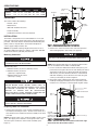
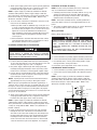
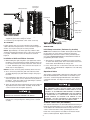
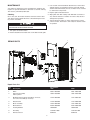
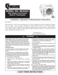
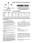
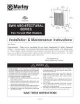
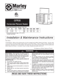
HTSS Series
Smart Series™ Wall Heater
IMPORTANT INSTRUCTIONS
READ CAREFULLY - This manual provides instructions for the correct installation, safe use, and care of this product. Special
attention should be directed to the warnings provided below which identify certain precautions and special instructions for safe and
efficient installation and use. Studying these instructions first may save you considerable time and money later and keep your
installation time to a minimum. If you are not familiar with electricity or feel uncomfortable in working with electricity, refer the installation of this product to a licensed electrician or qualified person.
WARNING
TO REDUCE THE RISK OF FIRE, ELECTRIC SHOCK OR
INJURY TO PERSONS:
1. READ ALL INSTRUCTIONS before installing or using the
heater.
2. ELECTRICAL SHOCK HAZARD: Disconnect all electrical
power coming to heater at circuit breaker box or main
disconnect switch and lock in OFF position before wiring.
All wiring must be in accordance with The National Electrical
Code and applicable local codes and ordinances.
The heater must be properly connected to an effective
building ground.
3. Verify the supply voltage coming to heater is the same as
shown on the heater nameplate before energizing.
Energizing at a voltage in excess of nameplate voltage will
damage heater and void warranty.
4. This heater has hot and arcing or sparking parts inside.
Do not install or use in areas where gasoline, paint, or flammable liquids are used or stored.
5. Do not install this heater upside down, sideways, in ceiling,
or floor. Install only as shown in this manual. Refer to
Mounting Clearances, page 2 for minimum clearances that
must be maintained.
6. The heater assembly must be installed in the back box provided. Do not operate the heater without the grille installed.
7. This heater is not approved for use in corrosive
atmospheres such as marine, green house or chemical
storage areas.
!
8. Do not use outdoors.
9. Extreme caution is necessary when any heater is used by or
near children or invalids and whenever the heater is left
operating or unattended.
10. This heater is hot when in use. To avoid burns, do not let
bare skin touch hot surfaces. Keep combustible materials,
such as furniture, pillows, bedding, papers, clothes, and
curtains away from heater. Do not block air intakes or
exhaust in any manner. For efficient and safe operation, we
recommend keeping all items at least 3 feet from front of
heater.
11. Do not insert or allow foreign objects to enter any ventilation
or exhaust opening as this may cause an electric shock or
fire, or damage the heater.
12. Should the heater become blocked or otherwise overheat, it
is provided with a manual-reset thermal safety switch and
alarm light that will activate to alert that the heater has
cycled off. If warning light is on, check to see if the reason
for the overheating can be identified. Remove any
blockage, allow heater to cool, then press Reset button.
Heater should return to normal operation. Do not continue
to use heater if it repeatedly cycles off. Have it inspected
and repaired by a qualified repair person.
11. Use this heater only as described in this manual. Any other
use not recommended by the manufacturer may cause fire,
electric shock, or injury to persons.
SAVE THESE INSTRUCTIONS
SPECIFICATIONS
MODEL
NUMBER
VOLTS
HT1502SS
120
HT2024SS
240
UNPACKING
AMPS
1.0 - 8.3
1.6 - 12.5
WATTS
250 - 2000
200 - 1500
BTUHR
853 - 6826
682 - 5120
WIRE
SIZE
Junction Box
Cover
14AWG
Back Box
12AWG
Heater Assembly
The carton contains the following:
• Remote control
• Bottom bezel
Screws
(8) Total
• Grille with installed electronics
• Heater assembly
• Installation Instructions and Userʼs Manual
INSTALLATION
The heater is designed for recessed installation in 2” x 4” (50
mm x 101 mm) stud or larger wall sections using the back box
provided. The heater may be wired with standard building wire
(60°C). Refer to “Specifications” and heater nameplate for
correct supply voltage and wire size.
Figure 1- Removing Heater Assembly From Back Box
NOTE: The optimum mounting height for this heater is 18” to
24” (450 to 600 mm) from floor to bottom of back box. DO NOT
install closer than 12” (305 mm) from the floor.
2. Remove one of the knockouts in the side of the back box
and install appropriate cable clamp (not supplied).
Mounting Clearances
TO PREVENT POSSIBLE DAMAGE TO POWER WIRING,
USE ONLY THE KNOCKOUTS PROVIDED IN BACK BOX.
Installation of Back Box in New Construction
TO PROVIDE FOR SAFE OPERATION, THE FOLLOWING
CLEARANCES MUST BE MAINTAINED.
NOTE: If the finished wall surface is already up, follow instructions for “Installation of Back Box in Finished Wall”.
Wall Mounting Only:
1. In new construction without the finished wall in place, position the back box against the side of stud allowing the side to
extend beyond the stud so it will be flush with the finished
wall surface. (You must know the thickness of the finished
wall when installing) Secure the box to the stud using two
screws (not included) as shown in Figure 2.
a. Minimum twelve (12) inches (305 mm) to floor;
b. Minimum twelve (12) inches
(305 mm) to adjacent walls;
c. Minimum thirty six (36) inches
(915 mm) to ceiling.
2. Run power supply cable through cable clamp (previously
installed) leaving approximately 6 inches (152 mm) of wire
inside box for connections to heater pigtails. Tighten clamp.
THE HEATER IS HOT WHEN IN USE. DO NOT INSTALL THE
HEATER BEHIND DOOR, BEHIND TOWEL RACK, IN
CLOSET, WHERE CURTAINS OR DRAPES COULD TOUCH
OR BECOME SCORCHED BY HEATER, OR WHERE
AIRFLOW TO HEATER MAY BE OBSTRUCTED.
KEEP ELECTRICAL CORDS, BEDDING, FURNITURE AND
OTHER COMBUSTIBLES AWAY FROM HEATER.
Stud
Ground Screw
Back
Box
Knock Out
TO PREVENT HAZARD OF FIRE OR ELECTRICAL SHOCK,
DO NOT INSTALL WITHOUT BACK BOX.
Preparing Heater For Installation
1. Remove the junction box cover / heater assembly from the
back box by removing 8 screws. Set the screws aside since
they will be used to reattach the heater assembly to the back
box later.
NOTE: The junction box cover / heater assembly consists of two
parts. The upper part is referred to as the junction box cover.
The lower part is referred to as the heater assembly. (See
Figure 1).
Hole with
Support Screw
(To Adjacent Stud
Where Possible)
2
Nails or Screws (2)
Figure 2 - Attaching Backbox to Stud
NOTE: The back box must be installed so the front edge
will be flush with the finished surface.
Installation of Heater Assembly
3. Attach power supply ground wire to green ground pigtail lead
using appropriate Listed wire nuts or approved connectors.
Push the wires into upper corner of box out of way.
NOTE: Use the screws provided by the factory, removed in
step 1 to install heater assembly to the back box.
NOTE: If power supply is provided by standard non-metallic
sheathed cable (Romex) and the supply voltage is 240 volts
(two power wires), the white wire color must be changed using
black electrical tape to comply with the NEC. White is only
allowed for a Neutral conductor.
1. Carefully position the heater assembly, with fan on top, and
element on bottom into the back box. Guide the flange
through the slot openings in the back box. This will help
guide the heater assembly into position.
NOTE: The heater assembly must be carefully positioned to
ensure the ribbon connector is not trapped behind the circuit
board.
4. To secure sides of back box not attached to stud, we recommend one of the following methods:
a. When possible, install an additional long screw (such as a
3” wood screw) through the lower side mounting hole into
the nearest stud (see Figure 2). Use care and do not overtighten the screw as this will deform the backbox and
make installation of the heater assembly difficult or impossible. Screw should only be tightened enough to keep
screw in place.
2. The heater assembly (lower portion) can now be attached to
the back box with 4 screws set aside in step 1
Wiring of Heater
Refer to wiring diagram Figure 3
b. Drill a small hole in back box flush with the inside surface
of the finished wall and install a screw (length not critical,
but should be at least 1 inch) see Figure 2.
POWER SUPPLY VOLTAGE MUST BE THE SAME AS
HEATER VOLTAGE RATING SHOWN ON HEATER NAMEPLATE. CONNECTING TO A VOLTAGE IN EXCESS OF
NAMEPLATE RATING WILL DAMAGE HEATER AND VOID
WARRANTY.
ALL CONNECTIONS MUST BE WITH APPROPRIATELY
SIZED LISTED WIRE CONNECTORS.
Installation of Back Box in Finished Wall
AN ELECTRICAL SHOCK, FIRE OR WATER DAMAGE
COULD RESULT IF WIRING OR PIPING IS DAMAGED
DURING CUTTING. MAKE SURE ALL WIRING AND PIPING
ARE CLEAR OF AREA BEFORE CUTTING.
FOR HEATERS RATED 120 VOLTS:
1. Connect the black (L1) heater pigtail to the black power lead.
2. Connect the white (N) heater pigtail to the white neutral lead.
3. If not already done, connect green heater pigtail to equipment ground wire coming into heater.
1. Locate a stud and carefully mark and cut a hole measuring
12-1/2” (318 mm) wide by 17-3/4” (451 mm) high so one side
of hole is along the edge of a stud – see Figure 2.
4. Push wires up into right hand corner of box out of way.
2. Run power supply cable through cable clamp (previously
installed) leaving approximately 6 inches (152 mm) of wire
inside box for connections to heater pigtails. Tighten clamp.
FOR HEATERS RATED 240 VOLTS:
1. Connect the black (L1) heater pigtail to the black power lead.
2. Connect the red (L2) heater pigtail to the other black power
lead.
3. Fit back box into opening aligning sides of box flush with finished wall surface and secure box to stud using two screws
(not included) as shown in Figure 2.
NOTE: If power supply is provided by standard non-metallic
sheathed cable (Romex) and the supply voltage is 240 volts
(two power wires), the white wire color must be changed using
black electrical tape to comply with the NEC. White is only
allowed for a Neutral conductor.
TIP: For proper spacing behind the back box upper flange, a
1/8” thick spacer can be used such as a metal yard stick or 1/8”
thick piece of wood, prior to final attachment of the back box to
the stud. This allows enough space for the grille to fit properly
over the back box flanges. Once back box is secured to the stud
the spacer can be removed.
G
Pilot
Light
N/L2
Manual Reset
Green Ground
4. Attach power supply ground wire to green ground pigtail lead
using appropriate Listed wire nuts or approved connectors.
Push the wires into upper corner of box out of way.
Black
White - 120 V
NOTE: If power supply is provided by standard non-metallic
cable (Romex) and the supply voltage is 240 volts (two power
wires), the white wire color must be changed using black electrical tape to comply with the NEC. White is only allowed for a
Neutral conductor.
Ribbon Cable
Red - 240 V
N
White
FANH
Black
FANM
Blue
FANL
Red
Sensor
3
Figure 3- Wiring Diagram
Triac
Red
White
Black
Control - Display Screen
Blue
Control-Power Board
Yellow
5. Insert one #8, three inch long wood screw (not provided)
through the free side of the back box not mounted to the
stud and secure in the lower ounting hole. This will prevent
the baack box from pull out on the unsupported side when
installing the heater assembly. Be careful not to drive the
wood screw more than 3/8” into the stud. Too much would
cause the back box to pull out of alignment. See Figure 2.
L/L1
Black
NOTE: Top flange must extend out from finished wall surface
approximately 1/8 inch (3.2 mm) to allow grill to attach.
Motor
Element
Ribbon Connector
Receptacle in
back of grille
Bottom Bezel
Red Warning
Light
Manual Reset
Safety Limit
Figure 4- Ribbon Connector
3. If not already done, connect green (G) heater pigtail to
equipment ground wire coming into heater.
4. Push wires up into right hand corner of box out of way.
ALL HEATERS:
Screw (2)
Position junction box cover in place making sure flat ribbon
cable is fitted into elongated slot in cover as shown in Figure 4.
Secure cover in place using the 4 screws provided.
Figure 5- Grille Screw Locations
OPERATION
Initial Setup Instructions (Performed by Installer)
NOTE: Approximately 3-1/2 inches (89 mm) of ribbon cable
should be extending through the slot for connection to electronics in grille. Orientation of connector must be as shown in
Figure 4.
Installation of Grille and Ribbon Connector
NOTE: After installation, the installer should perform the following procedures to ensure proper operation of the heater.
Programming of the heater controls can be performed by the
user. (See OPERATION MANUAL included with the heater for
programming the heater controls)
NOTE: Press the connector gently and firmly, but do not force.
2. Press “Power ON” Icon located in the lower left corner of the
display. The Icon will illuminate a bright blue color, indicating
the heater is ON.
1. After heater is completely assembled, turn power to heater
on at the main switch panel. The “Power” button on the front
of the heater should illuminate an orange color.
1. While holding the right side grille in your right hand, extend
the ribbon connector with the free hand and fit the black connector into the black slot located on the back of the electronic control, behind the grille. The connectors are keyed so it
will fit only one way (Figure 4).
Operational Notice
2. Once connected, position the grille over heater back box
assembly aligning top of grille with the flanges along top of
back box.
This heater is equipped with a manual-reset safety limit control
that will automatically turn off the heater if it overheats to prevent a fire. A red warning light will illuminate to alert that this
control had activated. See Figure 5 for the location of these
devices.
3. Reach behind the grille and push excess ribbon back into the
slot in the junction box cover to avoid unnecessary bends in
the ribbon. Lower top of grille so the grille flanges catch the
back box flange and hold it in place.
4. There are two holes in the bottom bezel area of the grille that
align with two holes in the heater assembly. Insert the two
screws in these holes and tighten (Figure 5).
THE ACTIVATION OF THE SAFETY LIMIT CONTROL AND
RED WARNING LIGHT OCCURS WHEN THE HEATER
OVERHEATS. CHECK HEATER TO MAKE SURE IT IS NOT
BLOCKED – IF SO, REMOVE THE BLOCKAGE. IF THERE IS
NO BLOCKAGE, IT IS RECOMMENDED THAT THE HEATER
BE INSPECTED BY A REPUTABLE ELECTRICIAN OR
REPAIR SERVICE TO ENSURE THE HEATER IS NOT
DAMAGED. DO NOT CONTINUE TO USE HEATER IF IT
REPEATEDLY CYCLES OFF ON THIS SAFETY LIMIT.
USE CARE AND DO NOT OVER TIGHTEN THE MOUNTING
SCREWS FOR THIS MAY DAMAGE THE GRILLE.
5. Place the lower bezel in position over the grille and snap
tabs into the corresponding holes making sure it is seated
securely.
TO RESET SAFETY LIMIT (SEE FIGURE 5)
4
The manual reset button is located behind the bottom bezel just
below the red warning light. To access the button, gently pull out
on the bottom tab of the bottom bezel and snap off. Do not use
a tool to remove the bezel, it may get damaged. Once the
heater has cooled, push the reset button. The heater should
return to normal operation. Replace the bezel.
MAINTENANCE
3. Use vacuum cleaner with brush attachment to remove dust
and dirt that has accumulated in heater (especially around
element and blower blade). Do not use water or any cleaners
to clean heater components.
Your heater is designed for years of trouble-free operation and
requires no special maintenance other than occasional cleaning.
The motor is permanently lubricated.
4. Replace grille and bottom bezel.
Cleaning
5. Wipe grille clean with a damp cloth. DO NOT use waxes or
any cleaners that leave a residue since these may discolor
during heater operation.
Once each year, the heater should be cleaned to remove dust
and other foreign material which has collected during the heating season, as follows:
6. Turn the main line switch on at the switch panel to restore
power to heater. The heater is now ready for another season
of operation.
ALL OTHER SERVICING SHOULD BE PERFORMED BY AN
ELECTRICIAN OR QUALIFIED PERSON
1. Turn power off at main switch.
2. Remove bottom bezel and the two screws that hold the grille.
REPAIR PARTS
1
5
3
2
9
8
6
4
7
Repair Parts List
Ref
No.
1.
2.
3.
4.
5.
6.
7.
8.
9.
Description
Grille
240V
1016-11035-000
1016-11035-000
2501-11003-000
Electronic Assembly
with top bezel
Motherboard, triac/heat sink, ribbon connector,
and sensor assembly (in one box):
1414-11007-000
Bottom bezel
1219-11004-000
Motor assembly
1225-11001-000
Manual Reset
4520-11005-000
Heating Element
302023802
Red lamp
Remote Control
Part Number
120V
3510-2017-000
5
SSRC1G
2501-11003-000
1414-11007-001
1219-11004-000
1225-11001-001
4520-11005-000
302023805
3510-2017-001
SSRC1G
LIMITED WARRANTY
All products manufactured by Marley Engineered Products are warranted against defects in workmanship and materials for one year from date of installation, except
heating elements which are warranted against defects in workmanship and materials for five years from date of installation. This warranty does not apply to damage from
accident, misuse, or alteration; nor where the connected voltage is more than 5% above the nameplate voltage; nor to equipment improperly installed or wired or
maintained in violation of the productʼs installation instructions. All claims for warranty work must be accompanied by proof of the date of installation.
The customer shall be responsible for all costs incurred in the removal or reinstallation of products, including labor costs, and shipping costs incurred to return products
to Marley Engineered Products Service Center. Within the limitations of this warranty, inoperative units should be returned to the nearest Marley authorized service center or the Marley Engineered Products Service Center, and we will repair or replace, at our option, at no charge to you with return freight paid by Marley. It is agreed that
such repair or replacement is the exclusive remedy available from Marley Engineered Products.
THE ABOVE WARRANTIES ARE IN LIEU OF ALL OTHER WARRANTIES EXPRESSED OR IMPLIED, AND ALL IMPLIED WARRANTIES OF MERCHANTABILITY AND
FITNESS FOR A PARTICULAR PURPOSE WHICH EXCEED THE AFORESAID EXPRESSED WARRANTIES ARE HEREBY DISCLAIMED AND EXCLUDED FROM
THIS AGREEMENT. MARLEY ENGINEERED PRODUCTS SHALL NOT BE LIABLE FOR CONSEQUENTIAL DAMAGES ARISING WITH RESPECT TO THE
PRODUCT, WHETHER BASED UPON NEGLIGENCE, TORT, STRICT LIABILITY, OR CONTRACT.
Some states do not allow the exclusion or limitation of incidental or consequential damages, so the above exclusion or limitation may not apply to you. This warranty gives
you specific legal rights, and you may also have other rights which vary from state to state.
For the address of your nearest authorized service center, contact Marley Engineered Products in Bennettsville, SC, at 1-800-642-4328. Merchandise returned to the factory must be accompanied by a return authorization and service identification tag, both available from Marley Engineered Products. When requesting return authorization,
include all catalog numbers shown on the products.
HOW TO OBTAIN WARRANTY SERVICE AND
WARRANTY PARTS PLUS GENERAL INFORMATION
1. Warranty Service or Parts
2. Purchase Replacement Parts
3. General Product Information
1-800-642-4328
1-800-654-3545
www.marleymep.com
470 Beauty Spot Rd. East
Bennettsville, SC 29512 USA
Note: When obtaining service always have the following:
1. Model number of the product
2. Date of manufacture
3. Part number or description
Part No. 5200-11046-000
PPD11565
03/10