1
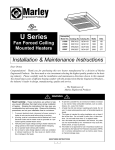
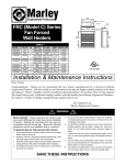
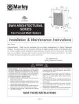
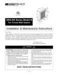
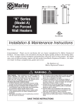
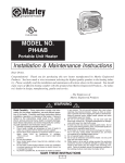
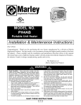
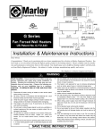
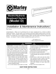
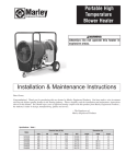
FILE #E21609
Model No. UH-524TA
Horizontal / Vertical Unit Heater
(Field Adjustable from 1.9KW @ 208V to 5KW@ 240V)
Installation & Maintenance Instructions
Dear Owner,
Congratulations! Thank you for purchasing this new heater manufactured by a division of Marley
Engineered Products. You have made a wise investment selecting the highest quality product in the heating industry. Please carefully read the installation and maintenance directions shown in this manual.
You should enjoy years of efficient heating comfort with this product from Marley Engineered Products...
the industry’s leader in design, manufacturing, quality and service.
... The Employees of
Marley Engineered Products
!
WARNING
6.
All electrical power must be disconnected at the main service
box before installing, inspecting, cleaning or servicing the
heater. This is a precaution to prevent serious electrical
shock.
7. This heater is not suitable for use in hazardous locations as
defined by the National Fire Protection Association (NFPA).
This heater has hot and arcing (sparking) parts inside. Do not
use in areas where gasoline, paint, or flammable liquids
are used or stored.
8. This heater is not suitable for use in corrosive atmospheres
such as marine green houses or chemical storage areas.
9. This heater must be mounted at least 6 feet (1829 mm) off the
floor.
10. This unit only operates on 240 or 208 volts AC. Improper
installation or failure to follow the procedures outlined in this
instruction manual can result in serious electrical shock.
Read Carefully - These instructions are written to help
you prevent difficulties that might arise during installation
of heaters. Studying the instructions first may save you
considerable time and money later. Observe the following
procedures, and cut your installation time to a minimum.
1.
2.
3.
4.
5.
Use minimum 60° copper wire only.
Heater air flow must be directed parallel to, or away from,
adjacent walls.
Observe wall, floor, and ceiling clearance requirements.
All wiring must conform to national and local electrical codes
and the heater must be grounded as a precaution against
possible electrical shock. Heater circuit must be protected
with proper fuses. See Table 1 on page 4.
The mounting structure and the anchoring hardware must be
capable of reliably supporting the weight of the heater and, if
used, the mounting bracket.
SAVE THESE INSTRUCTIONS
1
Mounting Height
When the air flow of the heater is directed vertically, the
minimum mounting height is 6 feet (1829 mm), the maximum
mounting height is 11 feet (3353 mm). When the air flow of the
heater is directed horizontally the minimum mounting height is 6
feet (1829 mm) and the maximum recommended height is 8 feet
(2438 mm).
INTRODUCTION
Your new heater has unmatched operating flexibility, designed
to meet a variety of heating requirements by simply switching
a few easily accessible wires located in the base of the unit.
With heat output ranging from 6,396 to 17,065 BTU per hour,
this unique feature lets you use a single unit to meet a wide
range of heating applications.
This manual shows you how to install, operate, and maintain
your UH-524TA electric heater.
Distance from Walls
When the heater is mounted so that the air flow direction is at
an angle from horizontal to 45° downward, the distance from the
mounting bracket to any wall should be at least 13 inches (330.2
mm). When the heater is mounted so that the direction of air
flow is at an angle between 45° downward and vertical, the distance from the mounting bracket to any wall should be at least
48 inches (1219 mm).
Unpacking Your New Heater
Remove the heater from the box and inspect it for any damage.
If it appears to be damaged, immediately return it to the store
from which you purchased it.
Check the contents of the box to make sure it contains one
heating unit and one mounting bracket.
1. Mounting the Bracket
Locate a stud in the ceiling and attach the mounting bracket to
the ceiling joist as shown in figures 3-A or 3-B. You will need to
remove the mounting bracket from the heating unit by loosening
the bracket screws with a wrench and slipping the handle off
over the screw heads. Remember to place a washer on the
screws before you insert them through the holes in the mounting bracket and screw them into the stud. Tighten the screws
enough to securely hold the heating unit with the air flow pointed in the proper direction.
Tools Needed
You will need the following tools to install your UH-524TA
electric heater:
• Screwdriver
• Needle nose pliers
• Pliers
• Electric Drill and 1/4" (6.35) bit
•Adjustable wrench
Hardware Needed
You will also need the following hardware for installation:
• Enough 10 ga. min. insulated copper conductor (with
ground) wire to run power from the breaker/ fuse to the
heater. Only use copper wire rated at least 60° C. Do not
use aluminum wire with this unit.
• Proper size fuses and circuit breakers in accor-dance
with the National Electrical Code. Also see Table 1, page
5.
• Screw wood, 3/8" x 2" (9.5 mm x 50 mm) Lag bolts (Qty.
1 or 2).
• Washer, 3/8" (9.7 mm) (Qty. 2)
• Wire connectors sized to your application.
NOTE: For certain applications, conduit may be required
(see Fig. 1). Check local electrical codes. Also, if you run
the wiring in conduit and wish to be able to turn the heater,
be sure to purchase enough flexible conduit to allow the
heater to be turned.
Figure 3-A
CEILING JOIST
WASHER
BRACKET
Single-Screw Mounting
3/8"
DIAGONAL
LAG BOLT
Figure 3-B
CEILING JOIST
WASHER
BRACKET
Conduit Conduit
Connector
Figure 1
Flexible Conduit
Flexible NM Cable
3/8"
DIAGONAL
LAG BOLT
Double-Screw Mounting
2. Hanging the Heater
Attach the heating unit to the mounting bracket. Lift the heater
up and into the mounting bracket. The bracket screws, located
on each side of the heating unit, allow the heater to be attached
easily to the mounting bracket by aligning the screws with the
keyhole slots in the mounting brackets. If the heater is to be tilted, it must be positioned in the lower keyhole slots (see Fig. 4).
Tighten the bracket screws with a wrench so the unit is securely suspended at the desired horizontal or vertical level.
Flexible Conduit Connector
Flexible NM Cable Connector
3. Connecting the Power
To connect the power to the heater, simply remove the screw
from the front of the unit. This allows the hinged bottom to open,
providing access to the electrical wiring and connectors. (See
Fig. 4)
Attach the cable connectors to the unit (See Fig. 1) and slide the
10 gauge wire through the cable connector. Pull enough of the
wire through the connector so you will have enough wire to work
with when you make the the connections.
Connectors, cable, and hardware used to wire the UH-524TA
FINDING THE BEST LOCATION
FOR YOUR HEATER
The heater should be installed out of traffic areas and at least 6'
off the floor. The direction of air flow should not be restricted (ie:
by columns or machinery) and the air flow should wipe exposed
walls, rather than blowing directly at them. When more than one
heater is used in an area, the heaters should be arranged so
that the air discharge of each heater supports the air flow of the
others to provide best circulation of warm air, as indicated in figure 2, below.
Figure 4
Figure 2
USE BOTTOM KEYHOLE
SLOTS IF HEATER IS
TO BE TILTED DOWN
2
REMOVE SCREW TO OPEN DOOR
NOTE: Wiring compartment volume = 370 in3 (6063 cm3)
Connect the wire to the power terminal block located in the base
of the heater (See Fig. 5).
NOTE: To decrease the heat output of the heating unit,
see Table 1 and schematic diagram on page 4.
Turn on the power at the main service.
NOTE: The louvers are designed so they can not be
completely closed. Do not attempt to defeat this feature,
damage to the unit can result.
ADJUSTING HEAT OUTPUT
Heat output can be increased or decreased by switching wires
at the wattage change terminal board. The heater is factory
wired to deliver a heat output of 17,065 BTU per hour. Should
your particular application require less heat output, refer to
Table 1 below and change the wires at the wattage change terminal board as shown in Wiring Diagram Fig. 7.
OPERATION
Figure 5
BOTTOM
VIEW
L2
TO PREVENT POSSIBLE ELECTRIC SHOCK, DISCONNECT POWER TO THE HEATER AT THE MAIN SERVICE
BOX BEFORE ATTEMPTING TO ADJUST THE HEAT OUTPUT OF THIS UNIT.
TABLE 1. HEAT OUTPUT ADJUSTMENTS
ITE
(or
G
Ba REE
re N
Co
pp
er)
WH
L1
WARNING
!
POWER
TERMINAL
BLOCK
BLA
CK
Setting the Thermostat
Rotate thermostat knob clockwise to high position. After room
reaches desired comfort level, rotate thermostat knob counterclockwise until the thermostat clicks off. (Note that the fan delay
will keep the fan running until the elements cool.) Heater will
cycle on and off to maintain room temperature.
NOTE: The first time you operate the unit, it may smoke
slightly. This is due to the residual cleaning agents used to
clean the element when the heater is manufactured. This is
normal and does not indicate a problem with the unit. This
condition will stop after the heater has been in operation
for a few minutes.
BTU/HR
VOLTS
WATTS
MAX
FUSE
SIZE
17065
240
5000
30
20.9
14215
240
4165
25
17.4
BLUE
11365
240
3332
20
13.9
BLUE & YELLOW
HEATER
AMPS
MOVE JUMPERS FROM
C-D TO A-B
NONE
8533
240
2500
15
10.4
BLUE, YELLOW & RED
12799
208
3750
25
18.0
NONE
10659
208
3123
20
15.0
BLUE
8533
208
2500
15
12.0
BLUE & YELLOW
6396
208
1874
15
9.0
BLUE, YELLOW & RED
MAINTENANCE
Figure 7
1
2
3
4
ELEMENT
5
6
RD
Automatic Fan Delay: The UH-524TA has an automatic fan
delay. When the thermostat calls for heat, fan action is delayed
momentarily until the heating elements warm. This prevents the
circulation of cold air. When the heater raises the temperature of
the room to the thermostat set point, the heating element is
turned off but the fan will continue to run until the heating element cools down. This prevents exposing the unit to residual
heat, provides a higher comfort level and prolonged element life.
YL
BLU
BLK
HI
LIMIT
FAN
CONT.
7
8
9
10
11
12
WATTAGE CHANGE
TERMINAL BOARD
C D
Thermal Cutout: The UH-524TA is also equipped with a
thermal cutout which will automatically shut off the heater in the
event of overheating. The heater will turn on when the operating temperature returns to normal. Should the unit overheat and
activate the thermal cutout cycle, the cause of the overheating
should be determined before further operation.
NOTE: If the unit is installed in an area where the temperature is below 50° F, the fan may cycle on and off until the
temperature in the room rises above 50° F, this is normal
and does not indicate a problem with the unit. As soon as
the heater warms the air in the room above 50°, the unit will
cycle normally.
AB
THERMOSTAT
FAN
MOTOR
GROUND
POWER
TERMINAL
BLOCK
L1
L2
FIELD
WIRING
SETTING THERMOSTAT
Because of its rugged design, superior engineering, and highquality craftsmanship, the UH-524TA requires little maintenance. With proper care, your electric heater should last a lifetime, but seasonal cleaning is recommended to maintain the
efficiency of the heater.
Adjusting Air Flow Direction
You can adjust the direction of air flow by:
A. Turning the unit. If the unit has been installed with a single
lag bolt, as shown in the Figure 6, simply turn the entire unit
as needed to adjust air flow.
B. Tilting the unit. Loosen the bracket screws, tilt the heater to
the desired position, and re-tighten the bracket screws (see
Figure 4).
NOTE: To tilt the heater it must be mounted in bottom key
hole slots of mounting bracket to maintain adequate clearance and prevent possible overheating.
C. Adjusting the louvers to the desired position.
!
WARNING
TO PREVENT POSSIBLE ELECTRIC SHOCK, ALL POWER
MUST BE SHUT OFF AT THE MAIN SERVICE BEFORE
INSPECTING OR CLEANING.
Cleaning the Heating Element
To clean the heating element, loosen (but do not remove) the
four Phillips head screws located behind the louvers in the corners of the louver housing. (See Fig. 8) Grasp the louver housing on both sides, lift up, and pull out. This provides access to
the heating element. Remove dust or lint with a soft brush or a
vacuum cleaner. Replace the louver housing and tighten the
Phillips head screws.
Figure 6
3
Dimension Data
Figure 8
HEATING ELEMENT
MINIMUM
DISTANCE
TO WALL
13 in.
(330.2 mm)
61/2 in.
(165 mm)
14 in. (356 mm)
125/8 in.
(321 mm)
MOUNTING
LOCATION
121/2 in.
(318 mm)
1/2 in., 3/4 in. (2)
(12.7 mm, 19.1 mm)
13/4 in.
(44.5mm)
Cleaning the Fan and Motor
FRONT VIEW
CAUTION
!
USE CARE TO PREVENT DAMAGE TO INTERNAL HEATER
WIRING WHEN CLEANING ELEMENT. MAKE SURE ALL
CONNECTIONS REMAIN TIGHT AND ALL WIRING IS
ROUTED AWAY FROM ELEMENT FINS WHEN REASSEMBLING THE UNIT. ALLOWING WIRING TO TOUCH THE ELEMENT FINS COULD RESULT IN A FIRE HAZARD.
All products manufactured by Marley Engineered Products are warranted
against defects in workmanship and materials for one year from date of
installation, except heating elements which are warranted against defects
in workmanship and materials for five years from date of installation. This
warranty does not apply to damage from accident, misuse, or alteration;
nor where the connected voltage is more than 5% above the nameplate
voltage; nor to equipment improperly installed or wired or maintained in
violation of the product’s installation instructions. All claims for warranty
work must be accompanied by proof of the date of installation.
The customer shall be responsible for all costs incurred in the removal or
reinstallation of products, including labor costs, and shipping costs
incurred to return products to Marley Engineered Products Service
Center. Within the limitations of this warranty, inoperative units should be
returned to the nearest Marley authorized service center or the Marley
Engineered Products Service Center, and we will repair or replace, at our
option, at no charge to you with return freight paid by Marley. It is agreed
that such repair or replacement is the exclusive remedy available from
Marley Engineered Products.
THE ABOVE WARRANTIES ARE IN LIEU OF ALL OTHER WARRANTIES EXPRESSED OR IMPLIED. AND ALL IMPLIED WARRANTIES
OF MERCHANTABILITY AND FITNESS FOR A PARTICULAR PURPOSE WHICH EXCEED THE AFORESAID EXPRESSED WARRANTIES
ARE HEREBY DISCLAIMED AND EXCLUDED FROM THIS AGREEMENT. MARLEY ENGINEERED PRODUCTS SHALL NOT BE LIABLE
FOR CONSEQUENTIAL DAMAGES ARISING WITH RESPECT TO THE
PRODUCT, WHETHER BASED UPON NEGLIGENCE, TORT, STRICT
LIABILITY, OR CONTRACT.
Some states do not allow the exclusion or limitation of incidental or con
sequential damages, so the above exclusion or limitation may not apply
to you. This warranty gives you specific legal rights, and you may also
have other rights which vary from state to state.
For the address of your nearest authorized service center, contact Marley
Engineered Products in Bennettsville, SC, USA, at 1-800-642-4328.
Merchandise returned to the factory must be accompanied by a return
authorization and service identification tag, both available from Marley
Engineered Products. When requesting return authorization, include all
catalog numbers shown on the products.
Remove the protective grille from the rear of the heater. This
provides access to the fan and motor. Wipe off the fan and
motor with a soft cloth or brush. The fan motor does not require
lubrication. Replace protective grille. (See Fig. 9.)
Figure 9
PROTECTIVE GRILL
FAN AND MOTOR
SPECIFICATIONS
Mounting Height, ft. (mm)
BTU per
Contactor Vertical Installation Horizontal Installation
Heater Rating and Voltage
Hr.
Phase Built-in
Min.
Max.
Min.
Max.
*5000 W @ 240V
4165W @ 240V
3332W @ 240V
2500W @ 240V
17,065
14,215
11,365
8,533
*3750W @ 208V
3123W @ 208V
2500W @ 208V
1874W @ 208V
12,799
10,659
8,533
6,396
SIDE VIEW
LIMITED WARRANTY
Min. Distance from
Horizontal Air
Throw, ft. (mm)
Mounting Hole to
Wall, in (mm)
1
No
6’
(1829)
11’
(3353)
6’
(1829)
8’
(2438)
18’
(5472)
**13”
(330)
1
No
6’
(1829)
11’
(3353)
6’
(1829)
8’
(2438)
18’
(5472)
**13”
(330)
*Heater is shipped from factory wired for these wattages. Heater can be field adjusted to the other wattages (Refer to “Adjusting the Heat
Output” on page 4.)
**48" (1219 mm) when heater air flow is between 45° downward and vertical.
HOW TO ORDER REPAIR PARTS
In order to obtain any needed repair or replacement parts, warranty service or technical information,
please contact Marley Engineered Products Service Center toll-free by calling 1-800-642-HEAT.
When ordering repair parts, always give the information listed as follows:
1. The Model Number
SPX Corporation
470 Beauty Spot Rd. East
Bennettsville, SC 29512 USA
2. The Part Description
3. Date of Manufacture
Part No: 5200-2252-000
SWO 259
05/95