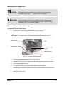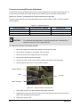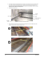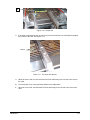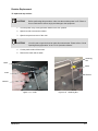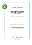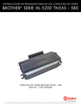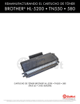
1
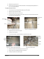
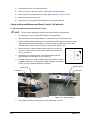
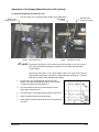
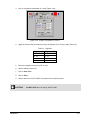
Conformal Curing Oven TC V3 Maintenance Manual P/N 7211568 NOTICE This is a Nordson ASYMTEK publication, which is protected by copyright. Original copyright date 2006. No part of this document may be photocopied, reproduced, or translated to another language without the prior written consent of Nordson ASYMTEK. The information contained in this publication is subject to change without notice. Manuals on the Internet For the convenience of Nordson ASYMTEK customers and field service representatives, copies of Nordson ASYMTEK manuals can be downloaded from: www.nordsonasymtek.com Contact Us Nordson ASYMTEK welcomes requests for information, comments, and inquiries about its products. Please contact us using the information below: Address 2762 Loker Avenue West Carlsbad, CA 92010-6603 USA Toll Free: Tel: 1-800-ASYMTEK (1-800-279-6835) +1-760-431-1919 Fax: +1-760-431-2678 E-mail: info@nordsonasymtek.com Website: www.nordsonasymtek.com USA: 1-800-ASYMTEK (1-800-279-6835) Other regions: www.nordsonasymtek.com Tech Support Technical Support Trademarks ® ® ® Asymtek , Century , and Easy Coat are registered trademarks of Nordson ASYMTEK. ® Nordson Electronics Systems is a registered trademark of Nordson Corporation. ® ® ® Microsoft , Windows , and Windows XP are registered trademarks of Microsoft Corporation. P/N 7211568, Revision C English Translation based on French P/N 7211572, Rev. B ©2010 Table of Contents 1 Introduction ...................................................................................................................................... 1-1 Overview............................................................................................................................................. 1-1 Safety First ......................................................................................................................................... 1-1 Hazardous Materials .......................................................................................................................... 1-1 2 Safety ................................................................................................................................................. 2-1 Overview............................................................................................................................................. 2-1 Facility Requirements ......................................................................................................................... 2-1 Basic Safety Precautions and Practices ............................................................................................ 2-2 Safety of Personnel .................................................................................................................... 2-2 Preventing Cure Module and Workpiece Damage ..................................................................... 2-2 Earthquake Precautions ..................................................................................................................... 2-3 Movement ................................................................................................................................... 2-3 Safety Warning Labels ....................................................................................................................... 2-3 Emergency Shutdown ........................................................................................................................ 2-3 Emergency Shutdown Recovery ................................................................................................ 2-3 Lockout of Electrical Energy ............................................................................................................... 2-5 Interlock ...................................................................................................................................... 2-5 3 Maintenance ...................................................................................................................................... 3-1 Overview............................................................................................................................................. 3-1 Safety First ......................................................................................................................................... 3-1 Recordkeeping ................................................................................................................................... 3-1 Periodic Maintenance ......................................................................................................................... 3-1 Preventive Maintenance ..................................................................................................................... 3-2 Maintenance Procedures ................................................................................................................... 3-3 Conveyor Torque Limiter Adjustment ......................................................................................... 3-3 Conveyor Incremental Encoder Adjustment ............................................................................... 3-4 Conveyor Chain Tension Adjustment ......................................................................................... 3-5 Transmission Chain Tension Adjustment ................................................................................... 3-6 Adjustment of the Rail Parallelism .............................................................................................. 3-7 Thermocouple Replacement .................................................................................................... 3-10 Resistor Replacement .............................................................................................................. 3-11 Setting of Upstream/Downstream Board Counter Cell (optional) ............................................ 3-14 Adjustment of the Dropped Board Detection Cell (optional) .................................................... 3-15 Auto-Tune Procedure ............................................................................................................... 3-16 4 Troubleshooting ............................................................................................................................... 4-1 Overview............................................................................................................................................. 4-1 Safety First ......................................................................................................................................... 4-1 Troubleshooting Alarms ..................................................................................................................... 4-1 5 Parts List ........................................................................................................................................... 5-1 Level 1 – Consumable Parts .............................................................................................................. 5-1 Level 2 – Recommended Parts .......................................................................................................... 5-1 Level 3 - Long Lead-Time Parts ......................................................................................................... 5-2 Table of Contents i Table of Figures Figure 3-1 Torque Limiter Adjustment ..................................................................................................... 3-3 Figure 3-2 Conveyor Counter Cell Location............................................................................................. 3-4 Figure 3-3 Conveyor Chain Location ....................................................................................................... 3-5 Figure 3-4 Transmission Chain Location ................................................................................................. 3-6 Figure 3-5 Conveyor Input ....................................................................................................................... 3-7 Figure 3-6 Conveyor Output .................................................................................................................... 3-7 Figure 3-7 Conveyor Transmission Gear ................................................................................................. 3-8 Figure 3-8 Input Rail ................................................................................................................................. 3-8 Figure 3-9 Mid-Section Rail...................................................................................................................... 3-8 Figure 3-10 Output Rail ............................................................................................................................ 3-9 Figure 3-11 Conveyor Rail Screws .......................................................................................................... 3-9 Figure 3-12 Thermocouple ..................................................................................................................... 3-10 Figure 3-13 Collar .................................................................................................................................. 3-11 Figure 3-14 Retaining Nut ...................................................................................................................... 3-11 Figure 3-15 Stuffing Box ........................................................................................................................ 3-12 Figure 3-16 Joint .................................................................................................................................... 3-12 Figure 3-17 Remount Joint..................................................................................................................... 3-12 Figure 3-18 Remount Mask.................................................................................................................... 3-12 Figure 3-19 Maintenance Part Screw .................................................................................................... 3-13 Figure 3-20 Maintenance Part Clip ........................................................................................................ 3-13 Figure 3-21 Remove Vitro-Ceramic Glass ............................................................................................. 3-13 Figure 3-22 Bride Location ..................................................................................................................... 3-13 Figure 3-23 Counter Cell ........................................................................................................................ 3-14 Figure 3-24 Signal Indicator ................................................................................................................... 3-14 Figure 3-25 Emitter Cell ........................................................................................................................... 3-15 Figure 3-26 Receiver Cell ........................................................................................................................ 3-15 Figure 3-27 Setpoint Box ....................................................................................................................... 3-16 Figure 3-28 Reg Z1 Button..................................................................................................................... 3-16 Figure 3-29 Graphic Visualization of Zone............................................................................................. 3-17 Figure 4-1 Troubleshooting Alarms.......................................................................................................... 4-1 Figure 5-1 Consumable, wearing parts, to be kept in-stock on production site. ...................................... 5-1 Figure 5-2 Parts recommended by the equipment manufacturer to be kept in-stock. ............................. 5-1 Figure 5-3 Parts with a long procurement lead-time or for software update............................................ 5-2 Table of Tables Table 3-1 Preventive Maintenance .......................................................................................................... 3-2 Table 3-2 Optional Encoders ................................................................................................................... 3-4 Table 3-3 Regulator ............................................................................................................................... 3-17 ii Table of Contents 1 Introduction Overview This manual covers maintenance procedures necessary for the preventive and corrective maintenance of the TC V3 Conformal Curing Oven. WARNING! Maintenance and troubleshooting procedures should only be performed by trained service technicians. Safety First Before performing any maintenance or troubleshooting procedures, it is important that you thoroughly read the TC V3 Operations Manual. Obey all written safety warnings in the Safety section, the warning labels affixed to your curing oven, and your facility safety practices. Hazardous Materials Some procedures may involve the use of hazardous materials. To prevent injury to personnel, follow all Federal, State, and local regulations, facility safety practices, and the material manufacturer's Material Safety Data Sheet (MSDS) recommendations. NOTE Introduction Consult safety and disposal precautions on the material manufacturer's Material Safety Data Sheet (MSDS) for all materials used with the cure module. 1-1 2 Safety Overview Operation of the TC V3 Conformal Curing Oven involves heat, electrical power, mechanical devices, and the use of hazardous materials. It is essential that every person servicing or operating the Cure Module fully understands all hazards, risks, and safety precautions described in this section. When properly operated and maintained, the Cure Module will be safe and reliable. This section is intended to provide basic safety information necessary for operating, maintaining, and servicing your TC V3 Cure Module. This section covers the following topics: • Facility Requirements • Safety Warning Labels • Basic Safety Precautions and Practices • Emergency Shutdown • Earthquake Precautions • Lockout of Electrical Energy Use of this equipment in ways other than those described in the documentation supplied with the equipment may result in injury to persons or damage to property. To further optimize safe operation, maintenance, and servicing of the TC V3, precautions and recommended practices are included with the procedures throughout this manual. WARNING! WARNING! Safety is considered a joint responsibility between the original equipment manufacturer and the end-user (owner). Safety precautions and practices should be in accordance with governing laws and regulations, and facility requirements in addition to those recommended in this manual. CAUTION! Unsafe equipment conditions can result in personal injury or property damage. Failure to properly operate and maintain the Cure module in accordance with this manual may jeopardize the built-in safety features. Facility Requirements To ensure optimal performance and safety, it is necessary to install the Cure Module in a facility that meets the necessary requirements. Refer to the Operations Manual for more information. Safety 2-1 Basic Safety Precautions and Practices The following precautions and practices are recommended during Cure Module operation and maintenance. Safety of Personnel • Only trained personnel should be permitted to perform operation, maintenance, service, and troubleshooting procedures. • All personnel working on or near the Cure Module should know the location of all electrical power supply sources. • Lock/tagout procedures must be performed before service or maintenance work is done on the Cure Module (refer to the "Lockout of Electrical Energy"). • Immediately push the red Emergency Off (EMO) button if personnel are in danger of being injured. • If in a confined room, ensure adequate and uninterrupted air ventilation, heating, and cooling to meet environmental stress limits of personnel and the Cure Module. • Follow MSDS recommendations for the proper handling, cleanup, storage, and disposal of hazardous materials. Know the MSDS recommendations for treatment of injury resulting from exposure to hazardous materials. Preventing Cure Module and Workpiece Damage • Immediately push the EMO button if the Cure Module or a workpiece is in danger of being damaged. • Use standard Electrostatic Discharge (ESD) precautions when working near ESD-sensitive components. Always wear a grounding strap and connect it to the ESD ground before handling work pieces. • Follow all recommended system maintenance procedures as outlined in the Maintenance Manual. • Ensure that no air intake or exhaust grilles are blocked while the Cure Module is in operation. WARNING! 2-2 CAUTION! Failure to comply with any of the safety recommendations could cause serious injury to personnel and/or damage to the equipment. Safety Earthquake Precautions In the event of an earthquake, the cure module must be secured to prevent movement that could cause injury to personnel and damage to the equipment and facility. Each Cure Module leveler (foot) should be anchored to the floor. to the TC V3 Operations Manual for Installation Procedures. WARNING! To prevent injury during an earthquake, all personnel should follow facility earthquake safety guidelines. Movement The TC V3 Cure Module is structurally designed to withstand seismic activity in accordance with industry standards. To prevent system movement during an earthquake, each leveler should be anchored to the floor with two bolts. The anchor joint should be able to withstand at least 100 kg (220 lbs.) of pullout force. Refer to the TC V3 Operations Manual for installation procedures. Safety Warning Labels Warning labels on your TC V3 Cure Module point out areas where personnel must use extreme caution to prevent injury or damage. WARNING! CAUTION! Comply with all safety warning labels or serious injury to personnel and/or damage to the equipment will occur. Worn or damaged labels should be replaced with new labels having the same part number. Emergency Shutdown The TC V3 Cure Module features an EMO button that the operator or service technician can use to immediately halt all system operations in case of emergency. This feature helps prevent injury to personnel and damage to the Cure Module and work pieces being processed. The EMO button is located on the front control panel of the cure module. The EMO cuts power to all system components. Emergency Shutdown Recovery WARNING! CAUTION! Do not restart the curing operation until the condition causing the emergency shutdown has been remedied. Failure to comply could cause serious injury to personnel and/or damage to the equipment. To recover after an Emergency Shutdown: Safety 1. Clear the Conveyor of all work pieces. 2. Lock out/tag out all system power. Refer to the TC V3 Operations Manual for lockout/tagout procedures. 3. Locate and remedy the cause of the emergency shutdown. Refer to the Troubleshooting section for more information. 2-3 2-4 4. Reset the main circuit breaker inside the electronics enclosure if it has been tripped. 5. Turn the red EMO button clockwise until it pops back into position. 6. Remove all warning tags and locking devices. 7. Restart the Cure Module. 8. Wait at least 30 seconds then push the reset button. Failure to do so could cause problems with the motor speed controller. 9. Open the Alarm window and reset alarms on the PLC. Refer to the TC V3 Operations Manual for alarm reset procedures. 10. Click on the Start button on the Main Menu. 11. Wait for temperature stabilization before running production. The alarm sounds at start up. Safety Lockout of Electrical Energy TC V3 Cure Module electrical components have been designed in accordance with industry-wide safety standards. However, precautions must still be taken whenever personnel may be exposed to the unexpected power-up of the equipment or release of hazardous electrical, ultraviolet, or microwave energy. Lock out and tag out electrical power before performing service or maintenance work on the Cure Module. WARNING! All personnel working on or near the Cure Module should know the location of all electrical power supply sources. WARNING! CAUTION! Failure to follow lockout/tagout procedures could cause serious injury to personnel and/or damage to the equipment. Interlock The Interlock is an electronic connection that immediately cuts power to any motion and pneumatic actuators. If the hood is opened during production, the interlock is activated and all curing activity immediately stops to protect the operator from injury. Safety 2-5 3 Maintenance Overview Performing the recommended maintenance and service procedures increases the life of your Cure module and ensures high quality performance for every production run. Safety First Before you proceed with TC V3 maintenance, make sure you understand the precautions in the Safety section and adhere to the precautions during the performance of maintenance procedures. CAUTION! Maintenance and service should be performed by trained personnel only. Recordkeeping At a minimum, the following information should be recorded in the cure module records: • Date • Procedure type • Technician name • Part/serial numbers of replaced parts • Post-procedure functional test results Periodic Maintenance Performing periodic maintenance procedures increases system life and ensures high quality curing performance for every production run. WARNING! Maintenance Unless otherwise specified, the Cure Module should be shut down while performing maintenance or troubleshooting procedures. Refer to “System Shutdown” in the TC V3 Operations Manual. 3-1 Preventive Maintenance Table 3-1 Preventive Maintenance Recommended Frequency WEEKLY – 120 h of Production Maintenance Procedure Grease chains Instructions The chains must not become dry. For proper chain lubrication, use only PERMA SO14-type oil (high temperature oil). NOTE WEEKLY – 120 h of Production Clean ceramic glasses Using any other kind of oil or grease can damage the conveyor. Clean the ceramic glasses each week. Depending on your level of production, it may be necessary to clean them more often. It is important to clean all varnish residues from the bottom glasses to ensure a good thermal transfer. Use a temperature recorder (Datapak, KIK, M.O.L.E. etc.) and a PCB (or other production item) equipped with thermocouples. MONTHLY 600 h of production Check reproducibility of the thermal cycle MONTHLY 600 h of production Check exhaust security control Stop the exhaust or disconnect the pipe. The oven must go into Alarm mode. If the oven doesn’t stop, check the functioning of the air flow sensor. THREE MONTH 1800 h of production Check control of speed displayed NOTE The results of this control must match the profiles previously obtained or the specifications given by the varnish provider. While the conveyor is running, use a stopwatch and measuring tape to determine how long it takes the conveyor to move a specified distance. Calculate the speed in cm/min. The calculated speed must be near the speed displayed on the screen (+/- 1 cm/min). NOTE Make sure that the measuring equipment used (watch and measuring tape) are calibrated. Push one of the emergency stop buttons. Check that the production stops. SIX MONTH 3600 h of production Check Emergency Stop buttons To restart the equipment, follow the procedure described in the TC V3 Operations Manual. NOTE Check the emergency stop buttons consecutively. SIX MONTH 3600 h of production Check conveyor gears When disassembling the conveyor chains, check the motion of each gear. If the gear does not turn freely, it must be changed. SIX MONTH 3600 h of production Check wear of the rails When removing the conveyor chains, check the rails for wear. When the chains are reassembled, they must slide freely along each sliding rail (forward and backward). ANNUAL 7200 h of production Check rails parallelism Measure the parallelism between the fixed rail and the mobile rail. It must not exceed +/- 0.5mm. 3-2 Maintenance Maintenance Procedures CAUTION! WARNING! Maintenance procedures should only be performed by trained service technicians. Refer to the Safety section for more information. Unless otherwise specified, the Cure Module should be shut down while performing maintenance or troubleshooting procedures. Refer to “System Shutdown” in the TC V3 Operations Manual. Conveyor Torque Limiter Adjustment To adjust the conveyor torque limiter: 1. Turn the power off by moving the Main Switch to the OFF position. 2. Remove the access cover at the output of the conveyor and set aside. NOTE The torque limiter is mounted on the motor shaft, behind the motor ( Torque Limiter ). Gear Allen Wrench Latch-tightening Screw Adjustment Ring Figure 3-1 Torque Limiter Adjustment 3. Unscrew the latch-tightening screw with an Allen wrench ( 4. Adjust the limiter by turning the adjustment ring to allow space to turn the gear by hand. 5. Tighten the latch-tightening screw. 6. Turn the power back on by moving the Main Switch to the ON position. 7. Before starting a production, activate the conveyor movement. Make sure the gear on the motor shaft does not slip. 8. Replace the access cover. Maintenance ). 3-3 Conveyor Incremental Encoder Adjustment The Conveyor Incremental Encoder returns an accurate measurement of conveyor speed to the PLC. In the TC oven, the encoder uses a close loop control to ensure the accuracy of the conveyor speed. Replace the encoder if it is damaged or the speed measurement is inaccurate. Various conveyor speeds can be used depending on the encoder installed. Table 3-2 lists the available encoder options. Table 3-2 Optional Encoders CONVEYOR SPEED ENCODER PART NUMBER DESIGNATION 80-400 050865 Encoder 360 pulses 160-800 (STANDARD) 050864 Encoder 200 pulses 300-1500 049615 Encoder 100 pulses CAUTION! For ovens built before May 2006, the speed measurement is controlled by an inductive sensor (VIT’s part number: 007546) To replace the Conveyor Incremental Encoder: 1. Remove the right hood in front of the machine, at the exit of the oven. 2. Fix the elastic couplings on the encoder and on the shaft. 3. Attach the encoder to the support bracket on the frame. 4. Plug the encoder jack into the female jack. 5. Turn the conveyor on and ensure that the encoder and shaft are properly aligned. 6. Verify the speed value on the control screen is correct. Support Bracket Shaft Encoder Elastic Coupling Figure 3-2 Conveyor Counter Cell Location 3-4 7. Check again to make sure the cell detects each tooth of the gear. 8. Recalibrate the close loop of the conveyor and check that the real speed of the conveyor is equal to the calculated speed by the PLC. 9. Replace the access cover. Maintenance Conveyor Chain Tension Adjustment To adjust the tension of the conveyor chains: 1. Turn the power off by moving the Main Switch to the OFF position. 2. Remove the access cover at the input of the conveyor and set aside. 3. Using an adjustable wrench, adjust the tension of the spring by turning the adjustment nut (Figure 3-3). 4. Make the same adjustment on the other side of the conveyor. Adjustment Nut Conveyor Chain Spring Figure 3-3 Conveyor Chain Location 5. Turn the power on by moving the Main Switch to the ON position. 6. Before starting a production, activate the conveyor movement and check that the conveyor chain turns without any jerk or noise. 7. Replace the access cover. CAUTION! Maintenance During production (oven in heating) check that the spring is still in tension. 3-5 Transmission Chain Tension Adjustment To adjust the tension of the transmission chain: 1. Turn the power off by moving the Main Switch to the OFF position. 2. Remove the access cover at the output of the conveyor and set aside. 3. Adjust the tension of the transmission chain by turning the chain tightener with a wrench (Figure 3-4). Chain Tightener Transmission Chain Figure 3-4 Transmission Chain Location 3-6 4. Turn the power on by moving the Main Switch to the ON position. 5. Before starting a production, activate the conveyor movement and check that the transmission chain turns without any jerk or noise. 6. Replace the access cover. Maintenance Adjustment of the Rail Parallelism If a printed circuit board (PCB) falls down into the oven, the conveyor rail needs adjustment. To adjust the conveyor rail parallelism: 1. Turn the power off by moving the Main Switch to the OFF position. Wait for the temperature to decrease to cool. WARNING! 2. Before performing this procedure, it is critical that you wait for the temperature to decrease to cool. Failure to do so could result in serious injury. Lift the hood to access the conveyor rails. CAUTION! 3. When opening the hood to make adjustments, refer to “Hood Opening/Closing Operation” in the TC V3 Operations Manual. With a slide caliper, measure the input width of the conveyor (Figure 3-5). A Figure 3-5 Conveyor Input 4. With the same slide caliper, measure the output width of the conveyor (Figure 3-6). B Figure 3-6 Conveyor Output Maintenance 3-7 5. If the input and output measurements are not equal, remove the access cover located under the crank to access the transmission gear. Unscrew the two locking screws (Figure 3-7). Insert one of the screws in the third hole to free the gear’s hub and tighten. Make necessary adjustments and replace the locking screws. 6. Replace the access cover. Locking Screw Hub Gear Insert screw here to free hub Locking Screw 7. Figure 3-7 Conveyor Transmission Gear Next, measure the width of the rail at the input (C) (Figure 3-8), at the middle section (D) (Figure 3-9), and at the output (E) (Figure 3-10). C Figure 3-8 Input Rail D Figure 3-9 Mid-Section Rail 3-8 Maintenance E Figure 3-10 Output Rail 8. If the three measurements are not equal, remove the screws from the rail fixation and adjust the position of the rails. See Figure 3-11. Screws Figure 3-11 Conveyor Rail Screws 9. While the oven is still cold, check that the PCB can slide freely from one side of the oven to the other. 10. Turn the power on by moving the Main Switch to the ON position. 11. When the oven is hot, check that the PCB can slide freely from one side of the oven to the other. Maintenance 3-9 Thermocouple Replacement To replace a thermocouple: 1. Turn the power off by moving the Main Switch to the OFF position. 2. Open the top rear access cover. 3. Disconnect the defective thermocouple from the connector (Figure 3-12). 4. 5. Unscrew the pressure screw. Remove the old thermocouple. 6. Replace with the new thermocouple. 7. Tighten the pressure screw. 8. Reconnect the thermocouple to the connector. Connector Thermocouple Pressure Screw Figure 3-12 Thermocouple 9. Check that the thermocouple is free to move inside the hole and is in contact with the ceramic glass. NOTE CAUTION! 10. 3-10 The spring will ensure a permanent contact between the thermocouple and the vitro-ceramic glass. If a good contact is not made between the thermocouple and the vitro-ceramic glass, the temperature reading will not be correct. On the PLC screen, make sure the temperature reading of the new thermocouple is correct. If not, repeat Step 9. Maintenance Resistor Replacement To replace the top resistor: CAUTION! Before performing this procedure, make sure the machine power is off. Failure to do so could result in serious injury and damage to the equipment 1. Turn the power off by moving the Main Switch to the OFF position. 2. Open the hood to access the resistor. 3. Open the top access cover of the oven. CAUTION! You will need to open the hood to make this measurement. Please refer to “Hood Opening/Closing Operation” in the TC V3 Operations Manual. 4. Cut the plastic collars off the mask. 5. Remove the mask and set aside. Retaining Nut Mask Cable Collar Resistor Resistor Figure 3-13 Collar Maintenance Figure 3-14 Retaining Nut 3-11 6. Unscrew the retaining nut on the cable. Figure 3-15 Stuffing Box Figure 3-16 Joint 7. Unscrew the nut on the stuffing box and remove the joint. 8. Replace the resistor. Resistor Cable Stuffing Box Collars Figure 3-17 Remount Joint 9. Remount joint in the stuffing box and tighten the screw. CAUTION! 3-12 Figure 3-18 Remount Mask To ensure proper positioning of the resistor, pull the resistor on the opposite side of the vitro-ceramic glass while locking the screw of the stuffing box (up if you change a resistor on the volt, down if it is on the plate). 10. Mount the cable and lock the retaining nut on both connections. 11. Remount the mask and lock it with new plastic collars on both connections. 12. Repeat Steps 4 through 9 on the remaining resistor connection. Maintenance 13. Replace the top access cover. 14. Close the hood using proper procedures described in “Hood Opening/Closing Operation” of the TC V3 Operations Manual. To replace the bottom resistor: 1. Turn the power off by moving the Main Switch to the OFF position. 2. Open the hood to access the resistor. 3. Open the bottom access cover of the oven. 4. To remove the vitro-ceramic glass, on the inside of the oven unscrew the screw and remove the clips from the maintenance part. Maintenance Part Maintenance Part Screw Clip Figure 3-19 Maintenance Part Screw Figure 3-20 Maintenance Part Clip 5. Repeat Step 4 for the other side of glass. 6. Carefully remove the glass. 7. To remove the resistor, unscrew the brides on each side and set aside. Allen Wrench VitroCeramic Glass Screw Brides Resistor Figure 3-21 Remove Vitro-Ceramic Glass Figure 3-22 Bride Location 8. Remove the resistor and carefully replace with the new one. 9. Secure in place by re-installing the brides on each side. 10. Maintenance Carefully re-install the vitro-ceramic glass. 3-13 11. Re-attach the clips on the maintenance part. 12. Check to make sure the new resistor is positioned in line with the glass. 13. Check the profile and auto-tune if necessary. Refer to the Auto-Tune Procedure. 14. Replace the bottom access cover. 15. Close the hood using procedures described in the Operations Manual. Setting of Upstream/Downstream Board Counter Cell (optional) To adjust the upstream/downstream board counter: NOTE For both cells (input/output) follow the same procedures as outlined below. 1. Turn the power on by moving the Main Switch to the ON position. 2. With a screwdriver, set scanning distance on the counter cell to max (Figure 3-23). 3. Position the board. Position light spot on board with red sender light spot visible on object. Signal strength indicator should light up. If it does not light up readjust the position and orientation and/or clean the photo-electric proximity switch (Figure 3-24). 4. Remove the board, signal strength indicator should go out (position A=max.). If it does not go out, turn switch towards min. until it goes out (e.g. position A). 5. Set switch to min. Position object. Turn switch towards max until signal strength indicator lights up (e.g. position B). 6. If position B<position A: Select middle setting (e.g. position C). Check complete functioning. Functioning OK, setting completed. Functioning not OK, check and readjust application conditions. Signal Indicator Counter Cell Screwdriver Light Spot Figure 3-23 Counter Cell 7. 3-14 Figure 3-24 Signal Indicator Check against another board to make sure the adjustment is correct. Maintenance Adjustment of the Dropped Board Detection Cell (optional) To adjust the dropped board detection cell: Emitter Cell (conveyor input) 1. Turn the power on by moving the Main Switch to the ON position. Adjustment Screw Figure 3-25 Emitter Cell Receiver Cell (conveyor output) Figure 3-26 Receiver Cell NOTES The emitter cell (Figure 3-16) is at the input of the conveyor, it has only one red LED. This red LED should always be switched on and represents the status “under voltage”. The receiver cell (Figure 3-17) is at the output of the oven, it has 2 LED. The red LED indicates input status (red light on = object detected, red light off = no object detected), the green LED indicates signal quality. 2. For each cell, turn the adjustment screw to the max position, then adjust the physical position of the receiver or emitter until the green LED light is on. 3. Turn the adjustment screw counterclockwise until the green light is off (position A). 4. Turn the screw in the middle position between max and A. 5. Check for positive detection with the board. 6. Check against another board to make sure the adjustment is correct. Maintenance 3-15 Auto-Tune Procedure The purpose of the auto-tune is to set PID parameters of temperature control loops. This function is used only if the regulation of a zone is not stable. Example: setpoint 120 and measure move from 110 to 130°C. PID are adjusted in factory before departure of the oven. WARNING! Never perform the auto-tune if not necessary. WARNING! Before activating the auto-tune, read through the complete procedure. IMPROPER HANDLING COULD DAMAGE THE OVEN. Do not perform the auto-tune procedure while the oven is running in production. To set PID parameters of temperature control loops: 1. Click on the setpoint box of a zone (Figure 3-27). Setpoint Box for Zone 1 2. Figure 3-27 Setpoint Box Click on REG Z1 to access the PID Loop Control (Figure 3-28). Access to the PID Loop Control Figure 3-28 Reg Z1 Button 3-16 Maintenance 3. Click on a graphical visualization of a zone (Figure 3-29). Figure 3-29 Graphic Visualization of a Zone 4. Apply the values below according to the type of regulator (PI or PID) you want (Table 3-3). Table 3-3 Regulator Regulator PI Regulator PID Gain : 1 Gain : 1 TI : 0 s TI : 0 s TD : 0 s TD : 9999 s ZR : 0 °C ZR : 0°C 5. Enter the temperature set point (150 °C max). 6. Wait for stability of the oven. 7. Click on Auto Tune. 8. Click on Start. 9. Wait for the end of "AUTO TUNE" and repeat for the remaining zones. CAUTION! Maintenance DO NOT STOP the oven during "AUTO TUNE". 3-17 4 Troubleshooting Overview Troubleshooting helps you identify common problems that you may experience with your cure module and offer suggestions for correcting them. Safety First Before you proceed with TC V3 troubleshooting, make sure you understand the precautions in the Safety section and adhere to the precautions during the performance of troubleshooting procedures. CAUTION! WARNING! Troubleshooting should only be performed by a trained service technician. Before troubleshooting the curing module, first turn OFF and disconnect all power to the unit. Reconnect power only as necessary for troubleshooting. Allow at least five seconds for the power supply high-voltage capacitor to discharge any residual energy. Do not touch metal parts that may contain voltage when power is ON. Troubleshooting Alarms Figure 4-1 Troubleshooting Alarms Alarms / Trouble Emergency Stop Alarm Exhaust Alarm Possible Causes Verifications and Actions Emergency button activated Pull and turn the emergency stop button to the right to restore to normal position. Press re-armament switch. Re-armament button not activated Press on the re-armament button to see if the button’s light switch is on. If not, check the wiring and the button. Security relay defective Check wiring and relay. Replace relay if defective. Pressure sensor defective or badly connected Check pressure sensor adjustment and pipe connection. Speed Sensor defective Check the sensor position and compare to the pinion teeth. Re-adjust if necessary. If the adjustment and the connection are good, change the sensor. Check the wiring. Alarm Conveyor 1 – Low Speed Alarm Troubleshooting Check the sensor. Change the sensor if it is defective. Fuse of the speed controller Check the fuse. Replace if necessary. AL1 higher than the setpoint speed defined in the recipe Check the value and decrease the AL1 value in the recipe. Bad calibration Recalibrate the conveyor (refer to the TC V3 Operations Manual). 4-1 Alarms / Trouble Alarm Conveyor 2 – Speed Band Alarm High Temperature Alarm (AL1) Temperature Band Alarm (AL2) Thermocouple Short Cut Alarm Thermocouple Broken Alarm Security Bar Alarm Open Hood Alarm Exhaust Alarm Possible Causes Verifications and Actions Speed Sensor defective Check the sensor position and compare to the pinion teeth. Check the wiring. AL2 too low Increase the value of the alarm band. Bad calibration Recalibrate the conveyor (Refer to the TC V3 Operations Manual). Bad PID loop tuning Perform an auto-tune procedure. Thermocouple defective Check the thermocouple wiring and location. It should be in contact with the vitro-ceramic glass. Bad PID loop tuning Perform an auto-tune procedure. Thermocouple defective Check the thermocouple wiring and location. It should be in contact with the vitro-ceramic glass. alarm band Value on recipe too small Increase the value in the receipt. Thermocouple defective Check the thermocouple wiring and location. It should be in contact with the vitro-ceramic glass. Bad PID loop tuning Perform an auto-tune procedure. zone Fuse or circuit breaker down Check the fuse or the circuit breaker. Resistor broken Check the resistor. Static Relay Check the relay. Thermocouple defective Change the thermocouple. Defective wiring Check the wiring. Security bar not in place Place the bar in the correct position. Sensor bad adjust Adjust the sensor. Reflector broken Replace the reflector. Hood close sensor defective Check the position and the wiring of the magnetic sensor. Circuit breaker/fuse of the electrical cylinder down Check the circuit breaker/fuse. Air flow Check the airflow and compare to the one specified. Increase the exhaust air flow if necessary. Flow pressure sensor defective Check the wiring of the sensor, the pipe connection, and the adjustment screw. PCB spacing length is Recipe error lower to PCB hole max length Correct recipe for having PCB spacing length higher than PCB hole max length. Loss Conveyor Parameters Recalibrate the conveyor (refer to the TC V3 Operations Manual). 1. Stop the Oven. 2. Open it. 3. Remove the board. Adjust the sensor (refer to the Conveyor Counter Cell Adjustment procedure) Conveyor parameters lost Board dropped Dropped Board Alarm Photo cell defective Check the wiring. 4-2 Troubleshooting Alarms / Trouble Possible Causes Verifications and Actions Photo cell defective Adjust the sensor (refer to the Conveyor Counter Cell Adjustment procedure) Check the wiring. Board Jam Alarm Improper alignment of the oven with the downstream machine Check and adjust the position of the downstream machine if necessary. Photo cell defective Adjust the sensor (refer to the Conveyor Counter Cell Adjustment procedure) Check the wiring. Input Transfer Alarm Downstream Alarm Improper alignment of the oven with the downstream machine Check and adjust the position of the downstream machine if necessary. Downstream machine down Check the downstream machine status. Lubricator Alarm Level Lower oil level Fill oil tank. Humidifier Alarm Check the humidifier status. Troubleshooting Humidifier error 4-3 5 Parts List This section contains parts ordering information for the TC V3 Conformal Curing Oven. Part number information is also available on Nordson ASYMTEK’s Find-A-Part web page: http://webstore.asymtek.com/awweblive/apps/findapart_index.asp WARNING! Parts replacement should only be performed by trained service technicians. Nordson ASYMTEK assumes no liability for personal injury or property damage that may occur as a result of spare parts being replaced by other than trained technicians. Level 1 – Consumable Parts Figure 5-1 Consumable, wearing parts, to be kept in-stock on production site. Designation Reference Manufacturer Solid state relay 35A CELDUC Regulation thermocouple - TCK Ø1.5 INO X 300 mm 630-09341 VIT Vitro-ceramic glass 200-38214 PRECIVER Fuse box 622-16868 VIT Conveyor speed sensor - XS1 N05 PA310 621-07546 SCHNEIDER Conveyor chain oil 654-13765 VIT Light tower bulb (set of 10) 624-15426 SCHNEIDER Level 2 – Recommended Parts Figure 5-2 Parts recommended by the equipment manufacturer to be kept in-stock. Designation Reference Manufacturer Air flow detector – Dwyer 1823-2 642-34576 DWYER Silicone rubber seal (process chamber) - 15X21 SIL 30A price for one meter 643-14716 PROGRESS Silicone cartridge DC732 654-07882 VIT Deflector entry 200-44979 VIT Deflector between vitro-ceramic glass (set of 3) 200-44978 VIT Set of 3 vitro-ceramic glasses 200-38214 VIT Aluminium pipe D80 640-43025 VIT Pin chain master link 683-16926 VIT Dropped board sensor – PZ-51P 621-07120 KEYENCE Gas Spring D8 C80 F450N 032616 VIT Chain guide / ball bearing (set of 8) 680-43206 VIT Parts List 5-1 Level 3 - Long Lead-Time Parts Figure 5-3 Parts with a long procurement lead-time or for software update. Designation Reference Manufacturer 24 VDC power supply 2.5A 627-46962 VIT Cooling fan 640-15814 VIT Safety relay (2NO 24Vdc) SIEMENS Tactile screen TP170B 620-40537 SIEMENS Siemens PLC power module 620-40528 SIEMENS SIEMENS PLC ET200S/IM151-CPU 620-40526 SIEMENS Siemens PLC 4 digital input ET200S/MOD 4DI/24VCC 620-40530 SIEMENS Siemens PLC 4 digital output ET200S/MOD 4DO 24VCC/0.5A 620-40531 SIEMENS Siemens PLC 2 analog tc input ET200S/MOD 2AI TC/RTD 620-40532 SIEMENS Siemens PLC 2 analog output ET200S/MOD 2AO STD +-10V 620-40653 SIEMENS Siemens PLC programming software for pc stepset Siemens PLC programming software for tactile screen : protocol SIEMENS 620-42079 SIEMENS Siemens PLC interface cable USB and hardware driver 620-47341 SIEMENS PCB sensor for SMEMA upstream or downstream 621-42130 BAUMER Motor and gear box 1440/320 682-38459 VARVEL Motor frequency controller – G110 / 0.25KW SIEMENS Centrifugal fan/intake blower – for 5.6 and longer 2650 m3/h 1500W 640-20177 VIT Safety sensor hood close 621-38236 SIEMENS Magnetic target hood close 621-38237 SIEMENS Sensor and reflector electrical wood lift 621-09212 / 621-38229 TELEMECANIQUE Resistor 2500w/400V – 3600w/480V 200-48165 VIT Resistor 1500w/400V – 2000w/480V 200-48163 VIT Klaxon Electric hood lift C500-F400 5-2 TELEMECANIQUE 681-36226 VIT Parts List Nordson ASYMTEK Headquarters 2762 Loker Avenue West Carlsbad, CA 92010-6603 USA Tel: (760) 431-1919 1-800-ASYMTEK (1-800-279-6835) P/N 7211568 Revision C ©2010