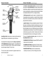
1
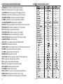
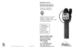
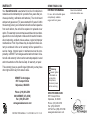
WARRANTY
SENSIT®GOLD G2
Your Sensit®Gold G2 is warranted to be free from defects in
materials and workmanship for a period of two years after purchase (excluding calibration and batteries). The circuit board
and percent gas sensor (TC) are warranted for 5 years. If within
the warranty period, your instrument should become inoperative
from such defects, the unit will be repaired or replaced at our
option. This warranty covers normal use and does not cover damage which occurs in shipment or failure which results from alteration, tampering, accident, misuse, abuse, neglect or improper
maintenance. Proof of purchase may be required before warranty is rendered. Units out of warranty will be repaired for a
service charge. Internal repair or maintenance must be completed by a SENSIT Technologies authorized technician. Violation will void warranty. Units must be returned postpaid, insured
and to the attention of the Service Dept. for warranty or repair.
INSTRUCTION MANUAL
This warranty gives you specific legal rights and you may have
other rights which vary from state to state.
SENSIT Technologies
851 Transport Drive
Valparaiso, IN 46383
Phone: (219) 465-2700
888 4 SENSIT (473-6748)
Fax: (219) 465-2701
www.gasleaksensors.com
INSTRUCTION MANUAL 1-7-2010 REV. 6-21-10 V 2.5
For use with combustible gases
and optionally available
oxygen and toxic gases.
Warning:
To prevent ignition
of flammable or
combustible
atmospheres,
disconnect power
before servicing.
SENSIT TECHNOLOGIES
851 Transport Drive
Valparaiso, IN 46383
Phone: (219) 465-2700
Fax: (219) 465-2701
US Toll Free: (888) 473-6748
www.gasleaksensors.com
Read and understand
instructions before use.
CONTENTS
NOTICE:
CAUTION: This safety symbol is used to
indicate a potentially hazardous situation which, if not
avoided, may result in minor or moderate injury.
NOTICE: LEL sensor should be checked for accuracy after
exposure to any gases containing silicones, high sulfur content,
high concentrations of propane and high concentrations of CO
(above 1000ppm) or exhaust gases.
Continuously low calibration check results or fluctuation of zero
readings may indicate sensor end of life or failure. Consult SENSIT
Technologies with any questions.
For best accuracy always zero in clean air environments similar in
temperature and relative humidity to the environment where the
instrument will be used. When continuously exposed to
combustible gas concentrations beyond LEL for longer than 5
minutes always perform a calibration check prior to the next use.
WARNING: To reduce the risk of ignition of a flammable
atmosphere, batteries must only be changed in an area known
to be nonflammable.
WARNING: Do not mix batteries of different age or type.
WARNING: Not for use in atmospheres of oxygen greater
than 21%.
WARNING: ONLY zero instrument in a gas free environment.
WARNING: To maintain intrinsic safety, service must be
performed by factory authorized technicians with approved
replacement parts only.
Page # 1
2
3
4
6
7
8
14
15
16
28
33
Back
Parts and Accessories
General Description
Specifications
Product Features
Sensor Types and Pumps
Battery Installation
Operation and Use
Bar Hole Test
Calibration Check (Bump Test page 21)
Menu
Calibration
Expert User Feature Chart
Warranty
PARTS AND ACCESSORIES
Standard Accessories (included)
Carrying Case, Alkaline Batteries, Wrist Strap, Extra Sensor Cap
with O-Rings and Instruction Manual
Accessories and Replacement Parts
ASG0150
Extension Adapter
AJN02039
Hydrocarbon Filter (10) (Barhole Probe with
filter required)
AJN02023
Hot Air Probe Assembly
AJN02017
81.3cm (32”) Fiberglass Bar Hole Probe w/Filter
AJN02013
Confined Space Probe with Tubing
AJN02021
Printer
AJN02033-PCIS PC Interface with Software
CSC00100
SMART-CAL™ Automatic Calibration System
PJN0110
Sensor Cap with O-Rings
Calibration Kits Contact factory for correct kit
1
GENERAL DESCRIPTION
GENERAL DESCRIPTION continued from page 2
The Sensit®Gold G2 is designed to detect combustible gases,
oxygen content and toxic gases when so equipped with the
available sensors. Each model of the Sensit®Gold G2 provides
specific detection features based on approved sensor options.
Each Sensit®Gold G2 can be re-configured or upgraded by the
manufacturer for an additional charge should your sensing requirements change.
When equipped with the optional percent volume sensor, alarms
remain activated up to 17% methane (12% propane). The carbon monoxide (CO) alarm is factory preset at 35ppm. The oxygen (O2) alarms are preset at below 19.5% and above 22.5%.
The hydrogen sulfide (H2S) alarm is preset at 10ppm. The hydrogen cyanide (HCN) alarm is set to 5ppm
Sensit Gold G2 configurations include measuring PPM, LEL
and/or % volume of combustible gases, measurement of oxygen, carbon monoxide, and/or hydrogen sulfide gas(es).
Sensit®Gold G2 instruments incorporate an advanced low power
semiconductor sensor to measure combustible gases in the
LEL (Lower Explosive Limit) range and a thermal conductivity
style sensor to measure combustible gases in the percent volume range. The user may select either methane or propane gas
readings from a user menu depending on the sensing requirements.
An automatically backlit display shows all gas concentrations
being measured. LEDs located on the front of the instrument
indicate preset visual warnings of increased gas concentration.
All gases are continuously sampled with the use of an internal
pump. Audible and visual alarms warn the operator of hazardous
conditions being sensed.
The preset alarms are indicated by a red flashing LED, display
indicator and alarm sound. The combustible gas alarm is preset
from 50% LEL (2.5% methane or 1.1% propane).
2
(Continued on page 3)
The Sensit®Gold G2 instrument is approved ATEX Zone 1 intrinsically safe Ex ib IIB T3 IP54. Consult Sensit Technologies
for certificate details.
APPROVED BATTERIES: Duracell MN 1400BK
SPECIFICATIONS
SENSOR SPECIFICATIONS
RESOLUTION
RANGE
0.1% up to 2%
increments
0-100% LEL
TYPE
LEL
%GAS
0.1%
PPM
1ppm or
10ppm increments
O2
CO
H2S
HCN
Size:
Weight:
Operational Temp:
Storage Temp:
Battery Life:
ACCURACY
±10%
5 -100% METHANE
2.2 - 100% PROPANE
±5%
0-2,000ppm
±10%
0.1%
0-25%
1ppm
0-2000ppm
1ppm
0-100ppm
1ppm
0-30ppm
** Whichever is greater
±0.2% or 2%**
±5ppm or 5%**
±2ppm or 5%**
±1ppm or 2.5%**
PRODUCT SPECIFICATIONS
292 x 76 x 59 mm
544 g
-20 to 40° C
-30 to 60° C
Alkaline: approximately 13 hrs. continuous
3
PRODUCT FEATURES
PRODUCT FEATURES
IR COMMUNICATION
LUER PROBE
CONNECTOR
SENSOR CAP WITH
WATER/DIRT FILTER
BACKLIT
GRAPHIC DISPLAY
LEAK/PPM/LEL
SENSOR
SPEAKER
(ON BACK)
ALL OTHER
SENSORS &
PUMPS (INTERNAL)
WARNING LEDs
16” FLEXIBLE
GOOSENECK
PUSH PAD
BUTTONS
BATTERY
COMPARTMENT
Sensit®Gold G2 instruments are constructed of durable high
impact ABS plastic to withstand the rigors of field use.
Incorporated in the hand grip area is the battery compartment.
All Sensit®Gold G2 instruments require 3 “C” type alkaline batteries. APPROVED BATTERIES: PROCELL® MN 1400 batteries provide approximately 13 hours of use.
The tick can be easily heard with the speaker located in the
back of the instrument.
4
(Continued on page 5)
continued from page 4
An infrared communication window is located on the right
side to allow the Sensit®Gold G2 instrument to download calibration data, readings the operator has elected manually to save
to the on board memory, as well as communicate with the SmartCal Calibration Station and PCI-2s computer interface.
A flexible gooseneck is used to assist in locating the source
of gas leaks and remote sampling. A water/dirt trap is located at
the end with a convenient luer style connector to attach sampling and probe accessories.
A graphic display continuously updates the operator of all available gas concentrations and alarms simultaneously as well as
indicates internal functions such as air flow and battery power.
Below the display is a series of LEDs that are preset to indicate
combustible gas concentrations. The red LED on the right side
will flash during any alarm condition. In darkened environments
the backlight will illuminate in red during alarm conditions.
There are 3 operational button pads on the front of all
Sensit®Gold G2 instruments.
• POWER/MUTE BUTTON (A): Operates POWER and MUTE
features and exit menu items.
• TICK/MENU BUTTON (B): Operates the Tick Rate Control,
Bar Hole Test and to enter, change and select menu items.
• SAVE/ZERO BUTTON (C): Use for save data feature,
manually zero sensors, scroll and change menu items.
5
SENSOR TYPES AND PUMPS
Combustible Gas Sensor
All Sensit®Gold G2 instruments incorporate a highly sensitive
and uniquely designed semiconductor sensor. The function and
accuracy of the sensor are monitored and controlled by specialized circuitry and a microprocessor. This sensor is capable of
measuring concentrations of as low as 1ppm methane up to
100% LEL. When equipped with the percent volume sensor,
concentrations above 70% LEL are monitored or measured simultaneously with a state-of-the-art thermal conductivity sensor
(TC). This sensor is capable of measuring high concentrations
of gas quickly and accurately. All readings are automatically
switched between the scales of PPM (if so equipped), LEL and
percent volume.
Electrochemical Sensors (optional)
All Sensit®Gold G2 instruments when equipped with the following optional sensors, microprocessor and associated circuitry
will measure oxygen levels from 0-25%, measure carbon monoxide (CO) levels from 0-2000ppm and measure hydrogen sulfide (H2S) levels from 0-100ppm. All gases are displayed simultaneously on the display.
The Pump
The Sensit®Gold G2 instruments are equipped with a powerful
and efficient rotary vane pump. A water/dirt filter at the end of
the gooseneck protects the pump from foreign material. An additional internal filter also helps to protect the pump from damaging debris. There are audible and visual indicators that will
show a blocked or improperly operating pump.
6
(Continued on page 7)
SENSOR TYPES AND PUMPS continued
NOTE: Operating the instrument without a sensor cap or
with an altered sensor cap can cause damage to the instrument and void the warranty.
BATTERY INSTALLATION/REPLACEMENT
A battery strength icon is located at the lower right corner of the
display which indicates the approximate battery capacity. Battery replacement is necessary when the display icon displays
an empty battery silhouette and flashes a countdown timer in
seconds indicating the maximum time before instrument shut
down. This timer begins at 300 seconds and decreases to 0.
During the low power indications the green LED will flash and a
warning beep will be sounded. Prior to shut down the display will
show BAT LOW in the main display.
CAUTION: Always change batteries in an environment
free of combustible gases.
Remove the battery sleeve cover by removing the retaining screw
(#10 Torx). Depressing the locking tab on the front of the handle
with a coin or flat object and pull the handle away from the top or
display area of the instrument.
NOTE: Observe the polarity markings on the inside of the
battery holder. Instrument will not operate with improperly installed batteries.
Never mix batteries of different type or age.
Place three (3) approved batteries into the battery holder. For
best results hold the battery compartment so that it lays in one
of your hands. With your other hand slide the first battery with
the negative (-) contact toward the battery spring. Insert the
(Continued on page 8)
7
BATTERY INSTALLATION/REPLACEMENT continued
OPERATION AND USE continued from page 8
remaining batteries in the same direction. The last battery will
contact the positive (+) tab at the end of the holder. If you do not
use one of your hands to hold the bottom of the battery compartment the batteries may come out.
Replace the battery sleeve and allow the locking tab to snap
into position. Replace and secure the retaining screw. Check to
be sure the handle is secure to the instrument body by firmly
pulling the handle away.
e. Date and Time
f. Gas Type (indicating type of calibration gas)
g. Serial Number
h. Cal Due (up coming) or Cal Past Due
i. Sensor Warm Up and Please Wait
j. Autozero (all gases and pressure sensor)
k. Auto Bump Test (optional)
l. Working display showing all gases sensed and battery
power remaining
2. If the display fails to illuminate or BAT LOW is shown on the
display, replace the batteries.
3. If any sensor is past the intended calibration cycle, CAL PAST
DUE will appear during the start-up sequence. The instrument
will also show which sensor is due for calibration at that time.
During “Autozero” all sensors will be displayed with the zeroing
result (passed or failed). Pressing and holding any button will
freeze the display screen during warm-up to allow extended viewing.
4. If after the warm-up period, the instrument determines that
a sensor is inoperable, an ERROR message will flash for
that sensor. Then FAIL will show on the display for the corresponding sensor. Attempt to manually zero using
SAVE/ZERO BUTTON(C).
5. The display will indicate the type of gas used for calibration
or to be sensed and the unit of measure (i.e.: LEL, PPM, %
VOL) below all readings.
See page 37 for optional configurations for the combustible gas
OPERATION AND USE
CAUTION: Always start any Sensit®Gold G2 in a gas
free environment to insure a proper zero.
1. Push the POWER/MUTE BUTTON (A) until the instrument
beeps and the display illuminates. Each of the following will be
displayed.
a. Sensit Technologies Logo
b. System check that includes:
i. LED check
ii. Backlight check
iii. Memory check
iv. Pump check
v. Battery check
vi. Microprocessor check
vii. Pressure sensor check
viii. Clock check
ix. Auto Log Check (alert at 50 records remaining
before memory is full and overwrites)
c. Display all active sensors
d. Display “SENSIT GOLD G2, Configuration Number and
Software revision”.
8
(Continued on page 9)
(continued on page 10)
9
OPERATION AND USE continued from page 9
OPERATION AND USE continued from page 10
detection display. If PPM display is selected, the measurement
auto-ranges to LEL at levels above 2000ppm. When equipped
with the optional percent volume sensor the measurement autoranges at 100% LEL. The display will indicate by changing the
unit of measure below the reading to “%v/v”.
be accomplished. This adapter slides onto the battery sleeve
and is held in place by the locking nut assembly.
6. Prior to use, test the integrity of the sensor cap and tubing.
Use your finger to block the inlet of the sensor cap for 4-5 seconds. The display will read FLOW BLOCKED if all seals are
intact. If this does not occur, change the sensor cap and “O”
rings. A spare sensor cap and “O” rings are supplied with each
instrument. During pump flow block, a beep will occur every 2
seconds and the green LED will flash until the pump restarts
and adequate flow is present.
7. It may be necessary to manually zero the instrument based
on company practices and environmental conditions. Always
zero the instrument in a clean air environment.
8. When testing areas with elevated temperatures such as appliance vents or flues, always attach the optional hot air probe to
the end of the sensor cap. These connections need only be
finger tight. Failure to use the approved probe can result in damage to the instrument and may void the warranty.
CAUTION: Do not handle the steel portion of any hot
air probe after use as burns may occur!
9. When sampling high areas or overhead lines the use of the
optional extension adapter will allow a broom handle or painters
stick to extend the instrument to the area where sensing must
10
(continued on page 11)
10. When sampling areas the appropriate sensors will cause
the display to update when a gas is encountered. Additionally, if
a combustible gas is encountered a series of LEDs on the front
of the instrument will illuminate when the preset concentrations
are reached. If any alarm condition exists for any sensor, based
on their preset alarm points, the red (HAZARD 3) LED will flash
and the alarm will sound unless it is muted.
Additionally, the reading for the gas exceeding the alarm set
point will also flash.
The standard factory preset LED indicators and alarm points
are:
a. Combustible gas: Methane, audio and visual alarm indicators
from 10% LEL to 100% LEL.
i. Green LED/Ready = 0% - 4.9%LEL Methane
ii. Amber LED/Low = 5% - 9.9%LEL Methane
iii. Red LED/Haz1 = 10.0% - 24.9% LEL Methane
iv. Red LED/Haz2 = 25.0% - 49.9% LEL Methane
v. Red Flashing LED/Haz3
METHANE: 50% LEL Methane to 17% volume* Methane
(LED indicator only above 17% volume Methane)
PROPANE: 50% LEL Propane to 12% volume* Propane
(LED indicator only above 12% volume Propane)
*When equipped with percent volume sensor.
b. Oxygen - below 19.5% and above 23.5%
(continued on page 12)
11
OPERATION AND USE
continue from page 11
c. Carbon Monoxide - 35ppm per utility industry standards
d. Hydrogen Sulfide - 10ppm and above per Federal OSHA
guidelines
e. Hydrogen Cyanide - 4.7 and above per Federal OSHA guidelines
Caution: There are gases that can poison or be cross
sensitive to the combustible gas sensor. Contact SENSIT
Technologies for cross-sensitivity information.
11. To disable the alarm, quickly press the POWER/MUTE
BUTTON (A). To enable the alarm press the same button again.
During an alarm the gas that has exceeded the preset alarm
point will flash on the display and the HAZARD 3 LED will flash
indicating a potentially unsafe condition. When combustible gas
readings exceed the alarm range, all LEDs (except green and
red HAZ3) will turn off. If the alarm condition no longer exists, the
alarm sound will activate if a new alarm condition is encountered.
12. To assist in locating small leaks press and release the TICK/
MENU BUTTON (B). Press the SAVE/ZERO BUTTON (C) until
SELECT TEST TICK is displayed. Push the TICK/MENU BUTTON (B) to activate the tick.
Upon activation a tick can be heard and a full bar graph is displayed. As the sensor head is moved toward a leak source the
tick will increase. At any time press the TICK/MENU BUTTON
(B) to reset the speed of the tick to the slow, steady rate. The
bar graph will decrease in size indicating a decreasing range of
tick rate sensitivity. Each bar division (there are 5) represents
approximately 5000ppm methane.
12
(continued on page 13)
OPERATION AND USE
continue from page 12
MENU BUTTON (B) to reset the tick so that is audible.
Pressing the POWER/MUTE BUTTON (A) disables the tick
As the sensor moves away from the gas source press the TICK/
function.
NOTE: Whenever possible use the instrument prior to using a leak detection solution.
13. At any time the operator may save the readings on the
display by pressing the ZERO/SAVE (C) button. This will save
all readings for download at a later time. The memory is factory
set to store 100 events. This can be adjusted from 1-100 at the
factory. The most recent save is first during download. An optional Auto log software of extended memory can store up to
1,600 records. (Consult factory for details.)
14. Following Federal, State, Municipal and/or Company procedures move to the areas where gas readings are suspected or
must be tested. Use necessary accessories to draw samples
from areas not accessible with the instrument itself, such as
confined spaces or flues. During sampling, the respective readings may change. Audible and visual alarms will activate when
the preset limits are reached.
15. When equipped with the percent volume sensor, if the instrument encounters a gas it is not calibrated to, it may read
“NSR” or “NSC” followed by a number. If the instrument is calibrated for natural gas “NSR” (Non Standard Response) likely
indicates a heavy non combustible gas (i.e.: heavier than air,
such as carbon dioxide, etc.). If the response is “NSC” Non
Standard Combustible) the gas is likely a heavy hydrocarbon,
such as gasoline, propane, butane, etc. If the instrument is
(continued on page 14)
13
OPERATION AND USE
continue from page 13
calibrated for propane, “NSR” likely indicates gas lighter than air
such as helium . “NSC” may indicate methane, hydrogen or
natural gas.
16. When being used in dark areas an automatic backlight will
illuminate the display.
17. To turn instrument off, press/hold the POWER/MUTE BUTTON (A) until the beeping sound stops and POWER OFF appears on the display. Release the button and shut down will
occur.
BAR HOLE TEST (For percent volume equipped units only)
To assist pinpointing the location of underground leaks the Bar
Hole Test feature may be used. This feature will draw a timed
sample (45 seconds) and display sustained and peak readings.
NOTE: Use an approved barhole probe with filter to prevent damage to the instrument when conducting bar hole
surveys.
To Conduct a BAR HOLE Test:
Prior to the test, attach the approved bar hole probe to an operating instrument. Block the inlets of the probe to test for any air
leakage. The instrument will show FLOW BLOCKED in approximately 10 seconds if all seals are good. If flow block is not
detected, check the integrity of the “O” ring seals and connections on the probe and instrument. If flow block can not be
achieved, contact the factory for assistance. An air tight system
is crucial for accurate readings.
From the working display, press & release the TICK/MENU BUTTON (B). SELECT TEST will appear on the top line of the
14
(continued on page 15)
BAR HOLE TEST continued from page 14
display. Press & release TICK/MENU BUTTON (B) to enter the
BH menu. Insert the bar hole probe into the location for the
survey. Press and release TICK/MENU BUTTON (B) once more
to start the test. A 45 second countdown for the test will begin.
The current percent of gas by volume detected will be displayed
on the left. The peak percent of gas by volume detected will be
displayed on the bottom. At the conclusion of the test, the pump
will shut off and any sustained and peak readings will be shown
and recorded.
If you have another test to take, press & hold the SAVE/ZERO
BUTTON (C). This will restart the pump and clear the last readings. When the readings have returned to zero, release SAVE/
ZERO BUTTON (C). The countdown timer will restart.
You may encounter NSR readings during the bar hole test (see
page 12 for definition). Changing the GAS TYPE, a selection in
the USER MENU may help to identify a questionable vapor. A
hydrocarbon filter kit is available to help screen if contact with
heavy hydrocarbons is suspected.
Please consult the factory for details. If you wish to cancel during a test or return to the working display, press & release the
POWER/MUTE BUTTON (A).
CALIBRATION CHECK
To verify the accuracy of any Sensit®Gold G2, it must be exposed to a known concentration of test gas that will test any
sensor combination included in your particular model.
Any sensor that does not meet the specifications listed in this
manual may require calibration or repair. A calibration check
(continued on page 16)
15
CALIBRATION CHECK continued from page 15
MENU
does not update the calibration due date. Full calibration is required to update these times.
A calibration past due message will illuminate during warm-up if
calibration has not been performed per your company specified
interval. Any time it is suspected that the Sensit®Gold G2 is
not working properly, check calibration.
CAL LOG: Display last calibration of all sensors.
SES LOG: Display saved gas readings with the corresponding
date and time.
PRINT: Print Session Logs, Cal Log, access Smart-Cal communication, (print CO test or print CF test is optional with some
extended memory units).
CAL DUE: Displays both future due dates and past due dates
for calibration.
SHOW BH LOG: Display the results from most recent BH tests.
MENU
The Sensit®Gold G2 has several categories within the User
Menu. The first nine fields are standard with all instruments. The
last three are only available in certain instrument models when
ordered with the Extended Memory option.
SHOW TIME: Displays current date and time. (Cannot be
changed from this location.)
SET TIME: Set date and time. Displayed using a 24 hour clock.
(User adjustable)
BUMP TEST: Perform automatic test for sensors response to
calibration gas within 60 seconds or less.
SMART-CAL: Configures instrument for operation and placement into automatic calibration station.
CAL: (not CALIBRATION) Remove SMART-CAL communication
and replace with “access AUTO CAL manual calibration procedures.
O2 TEST: 20 second test to check depletion of the O2 sensor
when exposed to the proper gas, such as 100% methane.
GAS TYPE: Select natural/methane or propane as primary gas
to be sensed.
16
(continued on page 17)
continued from page 16
Standard LOG size is 6 events but up to 100 records can be
stored per session, BH Test, CO Test and CF test.
NOTE: These additional fields are found on certain models ordered with the Extended Memory option.
AUTOLOG: Automatic storage of peak gas readings of up to
1,600 events.
SHOW CO TEST: Display CO levels recorded during timed test.
SHOW CF TEST: Display calculated AIR FREE CO levels recorded during timed test.
SHOW TIME
From the working display, access the menu by pressing and
holding the TICK/MENU BUTTON (B) until the display reads
USER MENU SHOW TIME. Press TICK/MENU BUTTON (B)
one time to display the time and date. Press any button to return to the USER MENU.
(continued on page 18)
17
MENU
continued from page 17
SET TIME
From the working display access the menu by pressing and
holding the TICK/MENU BUTTON (B) until the top line reads
USER MENU SHOW TIME. Press & release the SAVE/ZERO
BUTTON (C) to scroll to USER MENU SET CLOCK.
Press the TICK/MENU BUTTON (B) to select this feature. The
day of the month will flash. Use the TICK/MENU BUTTON (B) to
change the date. Using the SAVE/ZERO BUTTON (C) will scroll
to the next item to change. Press the POWER/MUTE BUTTON
(A) to save the changes and return to the USER MENU.
PRINT
From the working display access the menu by pressing & holding the TICK/MENU BUTTON (B) until the top line of the display
reads USER MENU SHOW TIME. Press the SAVE/ZERO BUTTON (C) to scroll to USER MENU PRINT MENU. Press the
TICK/MENU BUTTON (B) to select this feature. PRINT MENU
SESS LOG will be displayed and the pump will turn off. Press
the SAVE/ZERO BUTTON (C) to scroll to the type of report to
print.
Prepare and align the printer. Use the TICK/MENU BUTTON (B)
to begin the printing. Do not block or interfere with the line of
sight between the printer and the instrument during the printing
time. Press POWER/MUTE BUTTON (A) to return to the USER
MENU. The pump will also restart.
18
(Continued on page 19)
MENU
continued from page 18
BUMP TEST
Prior to starting this test prepare the necessary gases per the
sensor configuration.
From the working display, pressing and holding the TICK/MENU
BUTTON (B) until the display reads USER MENU SHOW TIME.
Press the SAVE/ZERO BUTTON (C) to scroll to USER MENU
BUMP TEST. Press the TICK/MENU BUTTON (B) to select this
feature.
Attach the prepared gas. During the test the gas type, the target
concentration, the time remaining in seconds and actual concentration will be displayed. After each gas is tested PASS or
FAILED will be displayed. It is not possible to manually stop the
test once it is started. At the end of the test BUMP TEST
(PASSED or FAILED) will be indicated. Press the POWER/MUTE
BUTTON (A) will save the results and return to the USER MENU.
SMART-CAL
From the working display, press & hold the POWER/MUTE BUTTON (A) for 2-3 seconds. The display will read SMART CAL
communicating.
Place the instrument into the cradle on the left side of the SmartCal Calibration Station. Attach the tubing from the station to the
instrument. Press & release the TICK/MENU BUTTON (B), the
display will show SMART CAL communicating.
Press & release the CALIBRATE button on the Smart -Cal and
calibration will begin automatically. If successful, CALIBRATION
PASSED will show on display. If unsuccessful, CALIBRATION
(Continued on page 20)
19
MENU
continued from page 19
FAILED will show. Let the instrument clear and repeat the calibration process. If the instrument will not pass, remove the instrument from service. Consult the factory in the event of any
failure.
CAL
See Calibration section on page 28.
O2 TEST
Prior to starting this test prepare the necessary gas (either
100% nitrogen or 100% methane)
From the working display press & hold the TICK/MENU BUTTON (B) until the display reads USER MENU SHOW TIME.
Press the SAVE/ZERO BUTTON (C) to scroll to USER MENU
O2 TEST.
Press the TICK/MENU BUTTON (B) to select this feature. Attach the prepared gas. During the test, the gas type and the
time remaining in seconds will be displayed. After the test PASS
or FAILED will be displayed. It is not possible to manually stop
the test once it is started. At the end of the test O2 TEST
(PASSED or FAILED) will be indicated. Pressing the POWER/
MUTE BUTTON (A) will save the results and return to the USER
MENU.
GAS TYPE
From the working display access the menu by pressing & holding the TICK/MENU BUTTON (B) until the display reads USER
MENU SHOW TIME.
Press the SAVE/ZERO BUTTON (C) until the display reads USER
20
(Continued on page 21)
MENU
continued from page 20
MENU GAS TYPE. Press the TICK/MENU BUTTON (B) to select this feature. Press the TICK/MENU BUTTON (B) to select
NAT for methane based calibration readings. Using the SAVE/
ZERO BUTTON (C) will select PRO for propane based calibration readings. Press the POWER/MUTE BUTTON (A) to save
the changes and return to the USER MENU.
CAL LOG
From the working display access the menu by pressing and
holding the TICK/MENU BUTTON (B) until the display reads
USER MENU SHOW TIME. Press the SAVE/ZERO BUTTON
(C) to scroll to USER MENU CAL LOG. Press the TICK/MENU
BUTTON (B) to select this feature.
The heading will display CAL DATE and the last calibration of
each sensor will be displayed. Press the POWER/MUTE BUTTON (A) to return to the USER MENU.
SES LOG
From the working display access the menu by pressing and
holding the TICK/MENU BUTTON (B) until the display reads
USER MENU SHOW TIME. Press the SAVE/ZERO BUTTON
(C) to scroll to USER MENU SES LOG. Press the TICK/MENU
BUTTON (B) to select the feature. The heading will display SESSION: XXX (indicating record number) and the date/time of the
record. Below will include the recorded concentrations of each
sensor installed. The SAVE/ZERO BUTTON (C) advances to
(Continued on page 22)
21
MENU
continued from page 21
the next record while pressing the TICK/MENU BUTTON (B) returns you back to the previous record. Press the POWER/MUTE
BUTTON (A) to return to the USER MENU.
MENU
continued from page 22
USER MENU SHOW TIME. Press the SAVE/ZERO BUTTON
(C) to scroll to USER MENU SHOW CF LOG.
NOTE: The following additional menu items can be only
found on certain models ordered with the extended
memory option.
Press TICK/MENU BUTTON (B) to select this feature. The last
two records will be displayed. The heading will display SES:
XXX (indicating record number) and the date/time of the record.
Below will include the recorded concentrations of each sensor
installed.
SHOW CO LOG
From the working display access the menu by pressing and
holding the TICK/MENU BUTTON (B) until the display reads
USER MENU SHOW TIME. Press the SAVE/ZERO BUTTON
(C) to scroll to USER MENU SHOW CO LOG.
The SAVE/ZERO BUTTON (C) advances to the next record while
pressing the TICK/MENU BUTTON (B) returns you back to the
previous record. Press the POWER/MUTE BUTTON (A) to return to the USER MENU.
Press the TICK/MENU BUTTON (B) to select this feature. The
last two records will be displayed. The heading will display SES:
XXX (indicating record number) and the date/time of the record.
Below will include the recorded peak (PK) and sustained (ON)
concentrations.
SHOW BH LOG
From the working display access the menu by pressing and
holding the TICK/MENU BUTTON (B) until the display reads
USER MENU SHOW TIME. Press the SAVE/ZERO BUTTON
(C) to scroll to USER MENU SHOW BH LOG.
The SAVE/ZERO BUTTON (C) advances to the next record while
pressing the TICK/MENU BUTTON (B) returns you back to the
previous record. Press the POWER/MUTE BUTTON (A) to return to the USER MENU.
Press TICK/MENU BUTTON (B) to select this feature. The last
two records will be displayed. The heading will display SES:
XXX (indicating record number) and the date/time of the record.
Below will include the recorded concentrations of each sensor
installed. The SAVE/ZERO BUTTON (C) advances to the next
record while pressing the TICK/MENU BUTTON (B) returns you
back to the previous record. Press the POWER/MUTE BUTTON (A) to return to the USER MENU.
SHOW CF LOG
From the working display access the menu by pressing and
holding the TICK/MENU BUTTON (B) until the display reads
22
(Continued on page 23)
(Continued on page 24)
23
MENU
continued from page 23
AUTO LOG
AUTOLOG (Automatically included with every unit that has the
optional CF Test feature)
From the working display access the menu by pressing and
holding the TICK/MENU BUTTON (B) until the display reads
USER MENU SHOW TIME. Press the SAVE/ZERO BUTTON
(C) to scroll to USER MENU AUTO LOG. Press TICK/MENU
BUTTON (B) to select this feature.
The heading will display SES: XXX (indicating record number)
and the TYPE of record (automatic or manually saved). Beneath
the heading will include the date of the session, start/stop time
and the recorded concentrations of each sensor installed.
The SAVE/ZERO BUTTON (C) advances to the next record while
pressing the TICK/MENU BUTTON (B) returns you back to the
previous record. Press the POWER/MUTE BUTTON (A) to save
the changes and return to the USER MENU.
With this feature the instrument will automatically save the peak
readings of all sensors while the unit is operating in the working
display. These peak readings are stored in Events with a maximum capacity of 1,600 events. They are stored accumulatively
throughout day to day use until the maximum capacity is
reached. Each use of the SAVE/ZERO BUTTON (C) to make a
manual save will also record one event.
24
(Continued on page 25)
MENU
continued from page 24
To Retrieve Autolog Events:
Stored autolog events can be downloaded to a PC using the
serial port computer interface PCI-2s (PCI-2s with software order #AJN02033-PCIS). Please contact the factory for more information on this accessory.
CAL DUE
From the working display access the menu by pressing and
holding the TICK/MENU BUTTON (B) until the display reads
USER MENU CAL DUE. Press the SAVE/ZERO BUTTON (C)
to scroll to USER MENU CAL LOG.
Press the TICK/MENU BUTTON (B) to select this feature. The
last two records will be displayed. The heading will display CAL
DATE and the last calibration of each sensor will be displayed.
Press the POWER/MUTE BUTTON (A) to return to the USER
MENU.
CONDUCT / SHOW /PRINT CF TEST
Only available as an option for instruments with CO and
O2 and the extended memory feature.
To Conduct a CF Test
NOTE: The hot air flue probe must be used with the instrument when conducting this test to prevent damage to the
instrument and to receive proper calculations.
IMPORTANT: Air free CO levels or CF readings are calculated by the instrument based on CO and O2 levels detected
during flue gas sampling of gas fired appliances.
(Continued on page 26)
25
MENU
continued from page 25
MENU
continued from page 26
From the working display, press & release TICK/MENU BUTTON (B) once, SELECT TEST will appear on the top line of the
display. Press & release the SAVE/ZERO BUTTON (C) until CF
is displayed. Press & release the TICK/MENU BUTTON (B)
again and the instrument will auto-zero and then enter the CF
test menu. Press & release the TICK/MENU BUTTON (B) once
more to start the test.
If the proper condition for an accurate test existed, the detected
CO level, calculated CF level and the peak CF level will remain
on the display at the end of the test.
NOTE: Using the SAVE/ZERO BUTTON (C) may advance you
to another test option depending on the instrument version.
Press & release the TICK/MENU BUTTON (B) to repeat the
test. Press & release the POWER/MUTE BUTTON (A) to return
to the working display.
The CF readings are automatically recorded by the instrument
and can be viewed at a later date. In addition, the peak CF
reading will be stored for a printout report.
A 180 second timed test will begin. (The time for this test is
factory adjustable.) A countdown timer will show the remaining
seconds of the test. The peak CF reading will start to flash “O
PK” in the lower right. 20 seconds after the oxygen level drops
below 18% indicating the presence of flue gas the PK reading
will no longer flash. A continuous CO reading is displayed in the
upper left and the sustained CF reading is in the upper right.
It will continue to flash until 20 seconds after the oxygen level
drops below 18.9%. At this point, conditions are acceptable for
a valid test calculation.
If this segment continues to flash during the test period,
conditions for a proper test were not possible. In this case
any test results are invalid. The display and printout will
show N/A for the peak CF reading. The test should be repeated.
26
(continued on page 27)
27
CALIBRATION
CALIBRATION continued from page 28
Calibration
Calibration is the process of setting the readings of the instrument to equal the value of certified calibration gases. Prior to
calibration allow the instrument to operate for 5 minutes in a
room environment free of combustible, CO and H2S gases.
• 50% LEL indicates calibration of the LEL and PPM
sensors.
Manually zero the instrument prior to beginning the calibration
process.
• 25 PPM H2S indicates the calibration point of the
hydrogen sulfide sensor.
NOTE: Using calibration kits other than recommended by
SENSIT TECHNOLOGIES may cause inaccurate readings.
Repairs are required if any sensor fails to calibrate. Consult SENSIT TECHNOLOGIES for details.
• 10 PPM HCN indicates the calibration point of the
hydrogen cyanide sensor.
NOTE: When calibrating, the numbers shown on the display represent the numbers seen by the microprocessor
and should not be confused with actual gas readings.
These readings will update every 5 seconds during calibration.
Definitions
• AUTO CAL is an automatic calibration process not
requiring a docking station.
• 2.5% V/V is the calibration point for the low end of the
100% volume sensor.
28
(Continued on page 29)
• 100 PPM CO indicates the calibration point of the carbon
monoxide sensor.
• SMART-CAL is the automatic calibration system using IR
communication.
Prior to starting calibration prepare the necessary gases per
the sensor configuration.
From the working display access the menu by pressing and
holding the TICK/MENU BUTTON (B) until the display reads
USER MENU SHOW TIME. Press the SAVE/ZERO BUTTON
(C) to scroll to USER MENU CAL .
Press the TICK/MENU BUTTON (B) to select from the various
calibration modes. The display will now show CAL AUTO CAL.
Pressing the SAVE/ZERO BUTTON (C) will allow viewing of all
other modes of calibration.
(Continued on page 30)
29
CALIBRATION continued from page 29
CALIBRATION continued from page 30
AUTO CAL automatically calibrates the instrument to all gases
detected by the sensors installed. From the AUTO CAL menu,
press the TICK/MENU BUTTON (B) . Attach the prepared gas
as listed on the display. A countdown timer shows the time remaining to connect . Failure to connect will result in a FAIL
message and an alarm sound (press any button to continue).
From this menu pressing the SAVE/ZERO BUTTON (C) again
will provide access to the SMART-CAL automatic calibration
system. Pressing the TICK/MENU BUTTON (B) from SMARTCAL menu begins the communication process. Consult the
SMART-CAL system instructions for connection details.
During the test, the gas type, the target concentration and digital output of the sensor (not concentration) will be displayed.
Following each gas tested PASS or FAILED will be displayed. It
is possible to manually stop the test once it is started by pressing the POWER/MUTE BUTTON (A).
NOTE: A calibration failure is indicated on the display by
FAILED. Re-calibration should be attempted. Any instrument that does not accept calibration should be taken out
of service. Please contact SENSIT TECHNOLOGIES for any
needed repairs.
At the end of the test BUMP TEST (PASS or FAILED) will be
indicated. Pressing the POWER/MUTE BUTTON (A) will save
the results and return to the USER MENU.
Pressing the SAVE/ZERO BUTTON (C) will scroll through the
individual sensors that are configured in your G2 for calibration.
Pressing the TICK/MENU BUTTON (B) selects the option. Attach the proper gas and wait for the instrument to provide a
PASS or FAILED indication.
If the calibration has failed press the POWER/MUTE BUTTON
(A) to attempt again or scroll to the next gas. Upon successful
calibration the calibration due date reminder is automatically
updated.
30
(Continued on page 31)
31
EXPERT MENU FEATURE DEFINITIONS
EXPERT USER FEATURE CHART
CONTRAST: Set display contrast for better viewing
TICK: Set normal speed of tick rate when resetting
%LEL MODE: Set to LEL display. If off readings are %V/V
100% LEL: Set the value of LEL between 4-5% methane
LEL RESOLUTION: Set reading increments on display
N COMP: Specialized sensor compensation software
CAL DUE REMINDER: Alert system for calibration
DUE ACK: Requires operator to push a button when cal is overdue
PROPANE 100%: Requires calibration to 100% propane
N2 for O2: Requires oxygen test using N2
SHOW SES LOG: Show the session log on display
SHOW BH LOG: Show bar hole test logs on display
SHOW CF/CO LOG: Show CO and CF test logs on display
ALARM SETTINGS: Limits for alarms
LOW LED: Concentration when first LED illuminates
POWER OFF: Automatic shut off time
PURGE TIME: Run time before instrument shut down after power off
BH TIME: Adjustment for the bar hole test time
CO TIME: Adjustment for the CO test time
ERASE AUTO: Erase the AUTO LOG
NG FACTOR: Factor for methane content in 100% natural gas
NSR: Disable gas distinguishing software
NSC: Disable combustible/inert identifier
NSC LEL: Concentration to activate NCS control
AUTO BUMP: Enable required bump test
TICK FIRST: Position of tick in menu
MUTE LATCH: If in mute, unit can remain until reactivated
ERASE LOG: Erase all sessions, BH, CO, CF Logs
CAL RQD: Set instrument to shut down after “Cal Past Due”
32
*OPTIONAL
33