1
RIGOL
Programming Guide
M300 Series
Data Acquisition/Switch System
Dec. 2013
RIGOL Technologies, Inc.
RIGOL
Guaranty and Declaration
Copyright
© 2013 RIGOL Technologies, Inc. All Rights Reserved.
Trademark Information
RIGOL is a registered trademark of RIGOL Technologies, Inc.
Publication Number
PGC07102-1110
Notices
RIGOL products are protected by patent law in and outside of P.R.C.
RIGOL reserves the right to modify or change parts of or all the specifications and pricing policies at
company’s sole decision.
Information in this publication replaces all previously corresponding material.
RIGOL shall not be liable for losses caused by either incidental or consequential in connection with
the furnishing, use or performance of this manual as well as any information contained.
Any part of this document is forbidden to be copied or photocopied or rearranged without prior written
approval of RIGOL.
Product Certification
RIGOL guarantees this product conforms to the national and industrial standards in China as well as the
ISO9001:2008 standard and the ISO14001:2004 standard. Other international standard conformance
certification is in progress.
Contact Us
If you have any problem or requirement when using our products or this manual, please contact RIGOL.
E-mail: service@rigol.com
Website: www.rigol.com
M300 Programming Guide
I
RIGOL
Document Overview
Main Contents in this Manual:
Chapter 1 Programming Overview
This chapter introduces how to build the remote communication between the instrument and PC. Besides,
it also provides an overview of the syntax, symbol, parameter type and abbreviation rules of the SCPI
commands as well as the SCPI status system.
Chapter 2 Command System
This chapter introduces the syntax, function, parameter and using instruction of each M300 command in
A-Z order.
Chapter 3 Application Examples
This chapter provides the application examples of the main functions of the Data Acquisition/Switch system.
In the application examples, a series of commands are combined to realize the basic functions of the Data
Acquisition/Switch system.
Chapter 4 Programming Demos
This chapter introduces how to program and control M300 using various development tools, such as Visual
Studio and LabVIEW.
Chapter 5 Appendix
This chapter provides various information, such as the command list and factory setting list.
The user documents of the product:
The main user documents of the product include quick guide, user's guide, programming guide and data
sheet. For the newest versions of these manuals, please download them from www.rigol.com.
Format Conventions in this Manual:
1
Button
The function key at the front panel is denoted by the format of “Button Name (Bold) + Text Box” in the
manual. For example, Utility denotes the Utility key.
2
Menu
The menu item is denoted by the format of “Menu Word (Bold) + Character Shading” in the manual.
For example, System denotes the System menu under Utility.
3
Operation Step
The next step of the operation is denoted by an arrow “” in the manual. For example, Utility
System denotes pressing Utility at the front panel and then pressing System.
4
Slot
The 5 slots are denoted by Slot1, Slot2, Slot3, Slot4 and Slot5 in the manual, wherein 1 to 5 denote the
slot numbers.
5
Channel
The channel is denoted by SCC in the manual, wherein S (ranges from 1 to 5) denotes the slot number
of the module and CC (ranges from 01 to 64) denotes the channel number.
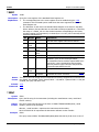
6
Module
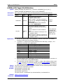
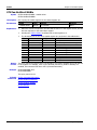
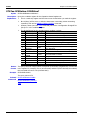
The definitions of the modules and their numbers are as shown in the table below. Unless otherwise
II
M300 Programming Guide
RIGOL
noted, “Multiplexer channels” refers to the MC3120, MC3132, MC3164, MC3232, MC3264 and MC3324
channels.
Model
MC3065
Name
DMM Module
MC3120
20-Channel
Multiplexer
MC3132
32-Channel
Multiplexer
MC3164
64-Single-Ended
Multiplexer
32-Channel Reed
Multiplexer
MC3232
MC3264
MC3324
64-Single-Ended
Reed Multiplexer
24-Channel
Multiplexer
MC3416
16-Channel Actuator
MC3534
Multifunction Module
MC3648
4×8 Matrix Switch
MC3724
Dual 4-Channel RF
Multiplexers
M300 Programming Guide
Explanation
Measure signals under test and perform statistical calculations
on the measurement results.
Support DCV, ACV, 2WR, 4WR, TEMP, FREQ, PERIOD and
SENSOR measurement functions; support scaling and alarm
functions.
Support DCV, ACV, 2WR, 4WR, TEMP, FREQ, PERIOD and
SENSOR measurement functions; support scaling and alarm
functions.
Support DCV, ACV, 2WR, TEMP, FREQ, PERIOD and SENSOR
measurement functions; support scaling and alarm functions.
Support DCV, ACV, 2WR, 4WR, TEMP, FREQ, PERIOD and
SENSOR measurement functions; support scaling and alarm
functions.
Support DCV, ACV, 2WR, TEMP, FREQ, PERIOD and SENSOR
measurement functions; support scaling and alarm functions.
Support DCV, ACV, DCI, ACI, 2WR, 4WR, TEMP, FREQ, PERIOD
and SENSOR measurement functions; support scaling and
alarm functions.
Switch signal to the device under test or actuate external
devices.
Channel 1 to Channel 4 are the DIO (Digital Input/Output)
channels; Channel 5 to Channel 8 are the TOT (Totalizer)
channels; Channel 9 to Channel 12 are the DAC
(Digital-to-Analog Converter) channels.
Connect multiple devices to multiple channels on the device
under test.
Consist of two independent 4-to-1 multiplexers and can switch
high frequency signal or pulse signal.
III
RIGOL
Contents
Contents
Guaranty and Declaration.......................................................................................................... I
Document Overview ................................................................................................................. II
Chapter 1 Programming Overview ..................................................................................... 1-1
To Build Remote Communication ................................................................................................ 1-2
Remote Control Methods ........................................................................................................... 1-4
SCPI Command Overview .......................................................................................................... 1-5
SCPI Status System ................................................................................................................... 1-8
Chapter 2 Command System .............................................................................................. 2-1
ABORt ...................................................................................................................................... 2-2
CALCulate Command Subsystem ................................................................................................ 2-3
CONFigure Command Subsystem ............................................................................................. 2-19
DATA Command Subsystem ..................................................................................................... 2-39
DIAGnostic Command Subsystem............................................................................................. 2-43
DISPlay Command Subsystem ................................................................................................. 2-47
FETCh? ................................................................................................................................... 2-49
FORMat Command Subsystem ................................................................................................. 2-50
IEEE-488.2 Common Commands .............................................................................................. 2-56
INITiate.................................................................................................................................. 2-64
INPut:IMPedance:AUTO........................................................................................................... 2-65
INSTrument Command Subsystem ........................................................................................... 2-66
LXI Command Subsystem ........................................................................................................ 2-67
MEASure Command Subsystem ................................................................................................ 2-68
MEMory Command Subsystem ................................................................................................. 2-82
MMEMory Command Subsystem............................................................................................... 2-90
OUTPut Command Subsystem.................................................................................................. 2-94
R? .......................................................................................................................................... 2-98
READ? .................................................................................................................................... 2-99
ROUTe Command Subsystem ................................................................................................. 2-100
SENSe Command Subsystem ................................................................................................. 2-115
SOURce Command Subsystem ............................................................................................... 2-185
STATus Command Subsystem ................................................................................................ 2-189
SYSTem Command Subsystem ............................................................................................... 2-198
TRIGger Command Subsystem............................................................................................... 2-226
UNIT Command Subsystem ................................................................................................... 2-231
Chapter 3 Application Examples ........................................................................................ 3-1
Scan List Configuration .............................................................................................................. 3-2
Monitor................................................................................................................................... 3-11
Store and Recall ...................................................................................................................... 3-12
Copy ...................................................................................................................................... 3-14
To Output Digital Signal ........................................................................................................... 3-16
To Output Analog Voltage ........................................................................................................ 3-16
Chapter 4 Programming Demos ......................................................................................... 4-1
Programming Preparations ......................................................................................................... 4-2
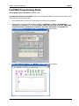
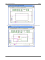
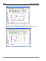
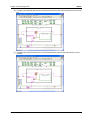
LabVIEW Programming Demo .................................................................................................... 4-3
C++ Programming Demo ........................................................................................................ 4-15
C# Programming Demo ........................................................................................................... 4-26
Chapter 5 Appendix............................................................................................................ 5-1
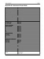
Appendix A: Factory settings ...................................................................................................... 5-1
Appendix B: Instrument Preset State .......................................................................................... 5-3
Appendix C: Non-volatile Memory............................................................................................... 5-5
Appendix D: Volatile memory ..................................................................................................... 5-6
II
M300 Programming Guide
Contents
RIGOL
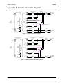
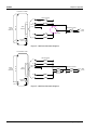
Appendix E: Module Schematic Diagram..................................................................................... 5-7
Appendix F: Command List ...................................................................................................... 5-11
Appendix G: Warranty ............................................................................................................. 5-20
M300 Programming Guide
III
Chapter 1 Programming Overview
RIGOL
Chapter 1 Programming Overview
This chapter introduces how to build the remote communication between the PC and instrument and
provides an overview of the syntax, symbol, parameter type and abbreviation rules of the SCPI commands
as well as the SCPI status system.
Main topics of this chapter:
To Build Remote Communication
Remote Control Methods
SCPI Command Overview
SCPI Status System
M300 Programming Guide
1-1
RIGOL
Chapter 1 Programming Overview
To Build Remote Communication
You can build the remote communication between M300 and PC over USB, LAN, RS232 or GPIB (IEEE-488)
interface.
Operation Steps:
1 Install the Ultra Sigma common PC software
Download the Ultra Sigma common PC software from www.rigol.com and install it according to the
instructions.
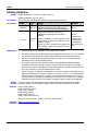
2
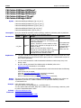
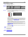
Connect the instrument and PC and configure the interface parameters of the instrument
M300 supports USB, LAN, RS232 and GPIB (IEEE-488) communication interfaces, as shown in the
figure below.
USB Device
LAN
RS232(can be
extended)
GPIB
Figure 1-1 M300 Communication Interfaces
(1) Use the USB interface:
Connect the USB Device interface at the rear panel of M300 and the USB Host interface of the PC
using a USB cable.
(2) Use the LAN interface:
Connect the instrument to your PC or the network of your PC using a network cable.
Check whether your network supports the DHCP or auto IP mode. If not, you need to enable
the manual IP mode, disable the DHCP mode and auto IP mode and acquire the network
interface parameters available (include the IP address, subnet mask, gateway and DNS) from
your network administrator.
Manually configure the IP address, subnet mask, default gateway, and DNS of the
instrument.
(3) Use the RS232 interface:
Use the mixed interface convert cable to convert the [RS232/Alarms/Ext Trig] interface
at the rear panel into two 9-pin interfaces, wherein one is a 9-pin male connector used as a
standard RS232 interface, the other is a 9-pin female connector for alarm output and
external trigger signal input, etc.
Connect the RS232 interface with the PC or data terminal equipment (DTE) using a RS232
1-2
M300 Programming Guide
Chapter 1 Programming Overview
RIGOL
cable. Press Utility I/O RS232, select Print and then select "No" to deisable the
measurement data print function of the RS232 interface.
Set interface parameters (baud rate, flow control and etc) which match the PC or terminal
equipment.
(4) Use the GPIB interface:
Connect the instrument with your PC (GPIB card is installed) using a GPIB cable.
Press Utility I/O GPIB to set the GPIB address of the instrument.
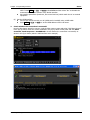
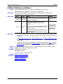
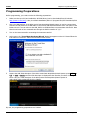
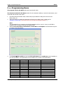
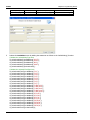
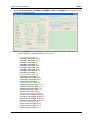
3
Check whether the connection is successful
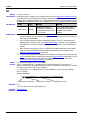
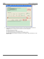
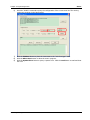
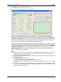
Run the Ultra Sigma, search for resource, right-click the resource name and select “SCPI Panel Control”
in the pop-up menu. Enter the correct command in the pop-up SCPI control panel and click Send
Command, Read Response or Send&Read to check whether the connection is successful, as
shown in the figure below (take the USB interface as an example).
M300 Programming Guide
1-3
RIGOL
Chapter 1 Programming Overview
Remote Control Methods
1.
Send SCPI Commands via the PC Software
You can control the M300 Data Acquisition/Switch System remotely by sending SCPI commands via the
PC software (Ultra Sigma) provided by RIGOL. Besides, you can also control the instrument using the
“Measurement & Automation Explorer” of NI (National Instruments Corporation) or the “Agilent IO
Libraries Suite” of Agilent (Agilent Technologies, Inc.).
2.
User-defined Programming
You can program and control the instrument using the SCPI (Standard Commands for Programmable
Instruments) commands listed in chapter 2 Command System in various development environments
(such as Visual Studio and LabVIEW). For details, refer to the introductions in chapter 4 Programming
Demos.
1-4
M300 Programming Guide
Chapter 1 Programming Overview
RIGOL
SCPI Command Overview
SCPI (Standard Commands for Programmable Instruments) is a standardized instrument programming
language that is built upon the standard IEEE488.1 and IEEE 488.2 and conforms to various standards
(such as the floating point operation rule in IEEE754 standard, ISO646 7-bit coded character for
information interchange (equivalent to ASCll programming)). This section introduces the syntax, symbols,
parameters and abbreviation rules of the SCPI commands.
Syntax
SCPI commands present a hierarchical tree structure and contain multiple sub-systems, each of the
commands consists of a root keyword and one or more sub-keywords. The keywords are separated by ":"
and are followed by the parameter settings available; "?" is added at the end of the command string to
indicate query; the command and parameter are separated by space.
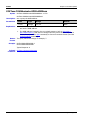
For example,
CALCulate:LIMit:LOWer:STATe <mode>,(@<ch_list>)
CALCulate:LIMit:LOWer:STATe? (@<ch_list>)
CALCulate is the root keyword of the command. LIMIt, LOWer and STATe are the second-level, third-level
and fourth level keywords respectively. The multiple-level keywords were separated by ":". <mode>
represents the parameter available for setting. "?" represents query. The command
CALCulate:LIMit:LOWer:STATe and parameter <mode> are separated by space. The parameters <mode>
and (@<ch list>) are separated by comma. The command CALCulate:LIMit:LOWer:STATe? and the
parameter (@<ch list>) are separated by space. "," is generally used for separating multiple parameters
contained in the same command, for example, SYSTem:DATE <yyyy>,<mm>,<dd>.
Symbol Description
The following four symbols are not the content of SCPI commands and will not be sent with the commands.
They are usually used to describe the parameters in the commands.
1.
Braces { }
The parameter enclosed in the braces is optional. It can be omitted or be set for one or more times. For
example, the CONFigure:CURRent:AC [{<range>|AUTO|MIN|MAX|DEF} [,{<resolution> |MIN| MAX|
DEF}],](@<scan_list>) command.
2.
Vertical Bar |
The vertical bar is used to separate multiple parameters and one of the parameters must be selected
when sending the command. For example, in the DISPlay OFF|0|ON|1 command, "OFF", "ON", "0" and
"1" are the optional parameters and one of them must be selected.
3.
Square Brackets [ ]
The content (command keyword) enclosed in the square brackets can be omitted. When the
parameter is omitted, the instrument will set the parameter to its default. For example, for the
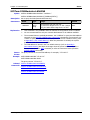
[SENSe:]CURRent[:DC]:APERture{<time>|MIN|MAX}[,(@<ch_list>)] command, sending any of the
four commands below can achieve the same effect.
[SENSE:]CURRent[:DC]:APERture {<time>|MIN|MAX}[,(@<ch_list>)]
[SENSE:]CURRent:APERture {<time>|MIN|MAX}[,(@<ch_list>)]
CURRent[:DC]:APERture {<time>|MIN|MAX}[,(@<ch_list>)]
CURRent:APERture {<time>|MIN|MAX}[,(@<ch_list>)]
M300 Programming Guide
1-5
RIGOL
4.
Chapter 1 Programming Overview
Triangle Brackets < >
The parameter enclosed in the triangle brackets must be replaced by an effective value. For example,
send the SYSTem:UTIlity:DISPlay:BRIGht <value> command in SYSTem:UTIlity:DISPlay:BRIGht 5
form.
Parameter Type
The parameters of the commands introduced in this manual contains 7 types: Scan list/Channel
list/Channel, bool, integer, discrete, numeric, ASCII character string and filename.
1.
Scan list/Channel list/Channel
The scan list parameter can be one or more channels. For example, in the
CONFigure:CURRent:AC[{<range>|AUTO|MIN|MAX|DEF}[,{<resolution>|MIN|MAX|DEF}],](@<scan
_list>) command, the parameter (@<scan_list>) can be (@301:302,215) (representing channel 01
through 02 on the module in Slot3 and channel 15 on the module in Slot2), (@201) (representing
channel 01 on the module in Slot2) or (@101:112) (representing channel 01 through 12 on the module
in Slot1). This parameter will reset the current scan list.
The channel list parameter can be one or more channels. For example, in the
[SENSe:]VOLTage[:DC]:NPLC {<PLCs>|MIN|MAX}[,(@<ch_list>)] command, the parameter
(@<ch_list>) can be (@301:302,215) (representing channel 01 through 02 on the module in Slot3 and
channel 15 on the module in Slot2), (@201) (representing channel 01 on the module in Slot2) or
(@101:112) (representing channel 01 through 12 on the module in Slot1). The current scan list will not
be affected by this parameter.
The channel parameter can only be a single channel. For example, in the ROUTe:SCAN:ADD
(@<channel>) command, the parameter <channel> can be (@213) (representing channel 13 on the
module in Slot2). The current scan list will not be affected by this parameter.
2.
Bool
The parameter can be OFF, ON, 0 or 1. For example, DISPlay OFF|0|ON|1.
3.
Integer
Unless otherwise noted, the parameter can be any integer within the effective value range. Note that
do not set the parameter to a decimal; otherwise, errors will occur. For example, in the
SYSTem:UTIlity:DISPlay:BRIGht <value> command, <value> can be any integer from 0 to 15.
4.
Discrete
The parameter can only be one of the specified values or characters. For example, in the
OUTPut:ALARm[<n>]:MODE {LATCh|TRACk} command, the parameter can be LATCh or TRACk.
5.
Numeric
Unless otherwise noted, the parameter can be any real number within the effective value range.
For example, the range of <time> in the
[SENSe:]CURRent[:DC]:APERture{<time>|MIN|MAX}[,(@<ch_list>)] command is from 33 µs to 4s.
6.
ASCII Character String
The parameter should be the combinations of ASCII characters. For example, in the
CALCulate:SCALe:UNIT <quoted_string>[,(@<ch_list>)] command, <quoted_string> is the unit of
the scaling parameter and can include English characters and numbers.
7.
1-6
Filename
The parameter represents the file name. The range of the parameter differs for the file with different
extension. The parameter can include English letters, Chinese characters, underline and numbers. For
details, please refer to the parameter description of the specific command.
M300 Programming Guide
Chapter 1 Programming Overview
RIGOL
Command Abbreviation
All the commands are case-insensitive and you can use any of them. If abbreviation is used, all the capital
letters in the command must be written completely. For example, the CALCulate:AVERage:SDEV? (@201)
command can be abbreviated to CALC:AVER:SDEV? (@201).
M300 Programming Guide
1-7
RIGOL
Chapter 1 Programming Overview
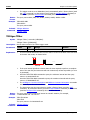
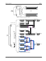
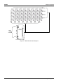
SCPI Status System
This chapter introduces the SCPI status system of M300.
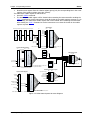
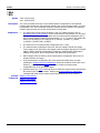
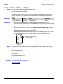
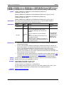
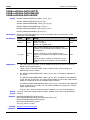
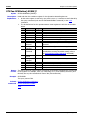
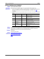
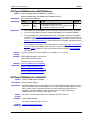
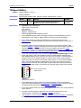
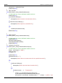
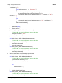
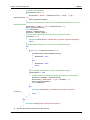
M300 status system is shown in Figure 1-2. The five register groups are used to record a variety of
conditions and status of the instrument. Each register group contains multiple underlying registers
(condition register, event register and enable register).
Condition register
The condition register monitors the instrument status continuously and the status of each bit is
updated in real time. The condition register is read-only and the bits will not be cleared when you read
the register. It returns a decimal value corresponding to the sum of the binary weights of all the bits in
the register when you query the condition register.
Event register
The event register latches the various events from the condition register. If the bit corresponding to an
event is set to 1, the subsequent events will be ignored. The event register is read-only. Once a bit is
set to 1, it remains set until cleared by a query command (such as *ESR?) or the *CLS command. It
returns a decimal value corresponding to the sum of the binary weights of all the bits in the register
when you query the event register.
Enable register
The enable register defines whether to report the event in the event register to the status byte register
group or not. The enable register could be read and written. You can use the STATus:PRESet command
to clear all the bits in the enable register and use the *PSC 1 command to configure the instrument to
clear all the bits in the enable register at power-on. To enable the bits in the enable register, write a
decimal value corresponding to the sum of the binary weights of all the bits in the enable register.
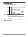
The Status Byte Register
The status byte register group reports the events from other register groups. For example, the system
error is reported to bit2 (Error generate). Clearing the event register of the relative register group will
clear the corresponding bits in the condition register of the status byte register group. For example,
clearing the error queue will clear bit2 (Error generate) in the condition register of the status byte
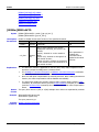
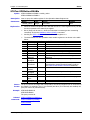
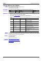
register group. The bit definitions of the status byte register are as follws.
Bit Weight
Name
Explanation
7
128
Operation
One or more bits are set in the operation status register
Status Summary (the bits must be enabled, refer to the
STATus:OPERation:ENABle command).
6
64
Master
One or more bits are set in the status byte register.
Summary
5
32
Standard Event
One or more bits are set in the standard event status
Status Summary register (the bits must be enabled, refer to the *ESE
command).
4
16
Message
Data is available in the output buffer.
Available
3
8
Questionable
One or more bits are set in the questionable status register
Status Summary (the bits must be enabled, refer to the
STATus:QUEStionable:ENABle command).
2
4
Error Queue
One or more errors have been stored in the Error Queue.
1
2
Alarm Summary One or more bits are enabled in the alarm register (the bits
must be enabled, refer to the STATus:ALARm:ENABle
command).
0
Not Used Not Used
Always be 0.
The status byte condition register is cleared when:
Send the *CLS command.
1-8
M300 Programming Guide
RIGOL
Chapter 1 Programming Overview
Read the event register from the relative register group (only the corresponding bits in the event
register of the relative register group are cleared).
The status byte enable register is cleared when:
Send the *SRE 0 command.
The status byte enable register will be cleared when restarting the instrument after sending the
*PSC 1 command to set the instrument to clear all the bits in the enable register at power-on. On
the contrary, the status byte enable register will not be cleared when restarting the instrument
after sending the *PSC 0 command to set the instrument to not clear all the bits in the enable
register at power-on.
Alarm Register
Alarm4 Queue Alarm3 Queue Alarm2 Queue Alarm1 Queue
1
2
1
2
1
2
1
2
.
.
.
.
.
.
.
.
.
.
.
.
99
100
99
100
99
100
99
100
Alarm 1
Alarm 2
Alarm 3
Alarm 4
SYSTem:ALARm?
Lower Limit
Upper Limit
MEM Overflow
EVR
ENR
0
Alarm 1
1
Alarm 2
2
Alarm 3
3
Alarm 4
4
5 Alarm Overflow
6
7
8
9
10
11
12
13
14
15
0
1
2
3
4
5
6
7
8
9
10
11
12
13
14
15
1
2
4
8
16
32
64
128
256
512
1024
2048
4096
8192
16384
32768
STATus:ALARm:CONDition? STATus:ALARm:EVENt? STAT:ALARm:ENABle <enable_val>
STAT:ALARm:ENABle?
Questionable Status Register
TOT Overflow
CR
Error Queue
CR
EVR
ENR
Volt Overload
0
Curr Overload
1
2
3
4
5
6
7
8
Res Overload
9
Temp Overload
10
11
12
13
14
15
0
1
2
3
4
5
6
7
8
9
10
11
12
13
14
15
1
2
4
8
16
32
64
128
256
512
1024
2048
4096
8192
16384
32768
1
2
..
.
Status Byte Register
CR
20
Output Buffer
..
.
STATus:QUEStionable:ENABle <enable value>
STATus:QUEStionable:CONDition?
STATus:QUEStionable:ENABle?
STATus:QUEStionable[:EVENt]?
0
1
2
3
4
5
6
7
*STB?
ENR
1
2
4
8
16
32
\
128
*SRE <enable_val>
*SRE?
Standard Event Status Register
Operation Status Register
CR
Calibrating
Self Test
Scanning
WFT
USB MSD detected
Config Change
Instrument Locked
Global Error
Busy
EVR
0
1
2
3
4
5
6
7
8
Mem Threshold
9
10
11 Settings Changed
12
13
14
15
STATus:OPERation:CONDition?
0
1
2
3
4
5
6
7
8
9
10
11
12
13
14
15
Operation Complete
ENR
1
2
4
8
16
32
64
128
256
512
1024
2048
4096
8192
16384
32768
STATus:ALARm[:EVENt]?
Query Error
Device Error
Execution Error
Command Error
Power On
EVR
ENR
0
1
2
3
4
5
6
7
1
2
4
8
16
32
64
128
*ESR?
*ESE <enable_val>
*ESE?
STATus:OPERation:ENABle <enable_value>
STATus:OPERation:ENABle?
Figure 1-2 M300 Status System Structure Diagram
M300 Programming Guide
1-9
Chapter 2 Command System
RIGOL
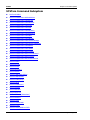
Chapter 2 Command System
This chapter introduces the syntax, function, parameter and using instruction of each M300 command in
A-Z order.
Main topics of this chapter:
ABORt
CALCulate Command Subsystem
CONFigure Command Subsystem
DATA Command Subsystem
DIAGnostic Command Subsystem
DISPlay Command Subsystem
FETCh?
FORMat Command Subsystem
IEEE-488.2 Common Commands
INITiate
INPut:IMPedance:AUTO
INSTrument Command Subsystem
LXI Command Subsystem
MEASure Command Subsystem
MEMory Command Subsystem
MMEMory Command Subsystem
OUTPut Command Subsystem
R?
READ?
ROUTe Command Subsystem
SENSe Command Subsystem
SOURce Command Subsystem
STATus Command Subsystem
SYSTem Command Subsystem
TRIGger Command Subsystem
UNIT Command Subsystem
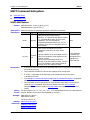
Note*: M300 provides a set of standard values for setting some parameters, such as the range, resolution and
integration time. When the parameter value sent is not one of the standard values, M300 will set the parameter
according to the “Using the greater value principle*” or “Using the smaller value principle*” (no error will be
generated).
Using the greater value principle*: if the specified value is different from the standard value of this parameter, the
first standard value of this parameter that is greater than the specified value will be selected for this parameter.
Using the smaller value principle*: if the specified value is different from the standard value of this parameter, the
first standard value of this parameter that is smaller than the specified value will be selected for this parameter.
M300 Programming Guide
2-1
RIGOL
Chapter 2 Command System
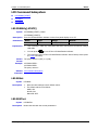
ABORt
Syntax
ABORt
Description
Abort the current measurement and stop the scan.
Explanation
The instrument stops the current scan when receiving this command and the scan
cannot be resumed. All the previous readings will be cleared when you initiate a new
scan.
The *RST command will abort the current measurement, clear the scan list, and set
all the measurement parameters to their factory settings. The SYSTem:PRESet
command can also abort the current measurement but it will not clear the scan list.
Example
ABOR
Related
commands
*RST
2-2
SYSTem:PRESet
M300 Programming Guide
Chapter 2 Command System
RIGOL
CALCulate Command Subsystem
M300 supports the scaling function and alarm function. You can configure the scaling parameters and alarm
parameters for the channels in scan list. The DMM module stores the measurement readings and performs
statistical calculations during the scan process. You can query the statistical calculation results at any time
(even during a scan). The CALCulate commands are mainly used to set the alarm parameters and scaling
parameters as well as query the statistical calculation results.
CALCulate:AVERage:AVERage?
CALCulate:AVERage:MAXimum?
CALCulate:AVERage:MINimum?
CALCulate:AVERage:PTPeak?
CALCulate:AVERage:SDEV?
CALCulate:AVERage:CLEar
CALCulate:AVERage:COUNt?
CALCulate:AVERage:MAXimum:TIME?
CALCulate:AVERage:MINimum:TIME?
CALCulate:COMPare:DATA
CALCulate:COMPare:MASK
CALCulate:COMPare:STATe
CALCulate:COMPare:TYPE
CALCulate:LIMit:LOWer
CALCulate:LIMit:UPPer
CALCulate:LIMit:LOWer:STATe
CALCulate:LIMit:UPPer:STATe
CALCulate:SCALe:SQUare
CALCulate:SCALe:GAIN
CALCulate:SCALe:OFFSet
CALCulate:SCALe:CONStant
CALCulate:SCALe:OFFSet:NULL
CALCulate:SCALe:STATe
CALCulate:SCALe:UNIT
M300 Programming Guide
2-3
RIGOL
Chapter 2 Command System
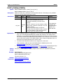
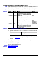
CALCulate:AVERage:AVERage?
CALCulate:AVERage:MAXimum?
CALCulate:AVERage:MINimum?
CALCulate:AVERage:PTPeak?
CALCulate:AVERage:SDEV?
Syntax
CALCulate:AVERage:AVERage? [(@<ch_list>)]
CALCulate:AVERage:MAXimum? [(@<ch_list>)]
CALCulate:AVERage:MINimum? [(@<ch_list>)]
CALCulate:AVERage:PTPeak? [(@<ch_list>)]
CALCulate:AVERage:SDEV? [(@<ch_list>)]
Description
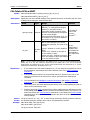
Parameters
Query the statistical calculation results (average, maximum, minimum, peak to peak and
standard deviation) of the readings of the specified channel.
Name
<ch_list>
Explanation
Return
Format
Example
Related
commands
2-4
Type
Range
Default
Channel
List
One or more channels (the multiplexer
channels, DIO channels or TOT channels), the
rules are as follows:
(@101): channel 01 on the module in Slot1;
(@101:103): channel 01 through 03 on the
module in Slot1;
(@101:103,301,406:408): channel 01
through 03 on the module in Slot1, channel 01
on the module in Slot3 and channel 06
through 08 on the module in Slot4.
If the parameter
is omitted, this
command will be
applied to the
whole scan list.
<ch_list> should be the multiplexer, digital or totalizer channels in the scan list. If the
specified channel is not in the scan list, the query returns +0.000000000E+00 (but no
error will be generated).
You can send command to read the statistical calculation results at any time, even
during a scan.
An error will be generated if the DMM module is disabled (refer to the
INSTrument:DMM command) or not installed.
The instrument clears the stored statistical data on all the channels under the following
conditions:
when a new scan is started;
when the CALCulate:AVERage:CLEar command is executed;
after a Factory Reset (send the *RSTcommand);
after an Instrument Preset (send the SYSTem:PRESet command);
The query returns the specified numbers in scientific notation. Multiple return values are
separated by commas. If no data is available for the specified channels, it returns
+0.00000000E+00.
CALC:AVER:MAX? (@101,102)
The query returns +3.853443855E-03,+4.074533140E-03
You can replace MAX with AVER, MIN, PTP or SDEV to query the average, minimum, peak
to peak or standard deviation value.
CALCulate:AVERage:CLEar
CALCulate:AVERage:COUNt?
CALCulate:AVERage:MAXimum:TIME?
CALCulate:AVERage:MINimum:TIME?
M300 Programming Guide
RIGOL
Chapter 2 Command System
CALCulate:AVERage:CLEar
Syntax
Description
Parameters
CALCulate:AVERage:CLEar [(@<ch_list>)]
Clear all the statistical calculation results (average, maximum, minimum, peak to peak,
standard deviation and count values) of the specified channels.
Name
Type
Range
One or more channels (the multiplexer
channels, DIO channels or TOT channels), the
rules are as follows:
<ch_list>
Explanation
Example
Related
commands
Channel
List
(@101): channel 01 on the module in Slot1;
(@101:103): channel 01 through 03 on the
module in Slot1;
(@101:103,301): channel 01 through 03 on
the module in Slot1 and channel 01 on the
module in Slot3.
Default
If the parameter
is omitted, this
command will be
applied to the
whole scan list.
<ch_list> should be the multiplexer, digital or totalizer channels in the scan list. If the
specified channel is not in the scam list, this command is invalid (no error will be
generated).
This command only clears the statistical calculation results of the specified channels
and no readings are cleared from the corresponding memory.
An error will be generated if the DMM module is disabled (refer to the
INSTrument:DMM command) or not installed.
The instrument clears the stored statistical data on all the channels under the following
conditions:
when a new scan is started;
when the CALCulate:AVERage:CLEar command is executed;
after a Factory Reset (send the *RST command);
after an Instrument Preset (send the SYSTem:PRESet command);
CALC:AVER:CLE (@101,102)
CALCulate:AVERage:AVERage?
CALCulate:AVERage:MAXimum?
CALCulate:AVERage:MINimum?
CALCulate:AVERage:SDEV?
CALCulate:AVERage:COUNt?
CALCulate:AVERage:PTPeak?
M300 Programming Guide
2-5
RIGOL
Chapter 2 Command System
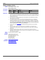
CALCulate:AVERage:COUNt?
Syntax
Description
Parameters
CALCulate:AVERage:COUNt? [(@<ch_list>)]
Query the number of readings taken on each of the specified channels.
Name
Type
Range
Default
One or more channels (the multiplexer
channels, DIO channels or TOT channels),
the rules are as follows:
<ch_list>
Explanation
Return
Format
Example
Channel
List
(@101): channel 01 on the module in Slot1;
(@101:103): channel 01 through 03 on the
module in Slot1;
(@101:103,301): channel 01 through 03 on
the module in Slot1 and channel 01 on the
module in Slot3.
If the parameter
is omitted, this
command will be
applied to the
whole scan list.
You can send command to read the statistical calculation results at any time, even
during a scan.
An error will be generated if the DMM module is disabled (refer to the
INSTrument:DMM command) or not installed.
The instrument clears the stored statistical data on all channels under the following
conditions:
when a new scan is started;
when the CALCulate:AVERage:CLEar command is executed;
after a Factory Reset (send the *RST command);
after an Instrument Preset (send the SYSTem:PRESet command);
The query returns the numbers of readings in scientific notation. Multiple return values
are separated by commas. If no data is available for the specified channels, it returns
+0.00000000E+00.
CALC:AVER:COUN? (@101,102)
The query returns +3.000000000E+01,+3.000000000E+01
Related
commands
CALCulate:AVERage:AVERage?
CALCulate:AVERage:MAXimum?
CALCulate:AVERage:MINimum?
CALCulate:AVERage:PTPeak?
CALCulate:AVERage:SDEV?
CALCulate:AVERage:CLEar
2-6
M300 Programming Guide
RIGOL
Chapter 2 Command System
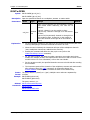
CALCulate:AVERage:MAXimum:TIME?
CALCulate:AVERage:MINimum:TIME?
Syntax
CALCulate:AVERage:MAXimum:TIME? [(@<ch_list>)]
CALCulate:AVERage:MINimum:TIME? [(@<ch_list>)]
Description
Parameters
Query the time that the maximum or minimum reading was taken on the specified channels
during the scan.
Name
Type
Range
One or more channels (the multiplexer
channels, DIO channels or TOT channels),
the rules are as follows:
<ch_list>
Explanation
Return
Format
Example
Channel
List
(@101): channel 01 on the module in Slot1;
(@101:103): channel 01 through 03 on the
module in Slot1;
(@101:103,301): channel 01 through 03 on
the module in Slot1 and channel 01 on the
module in Slot3.
Default
If the parameter
is omitted, this
command will be
applied to the
whole scan list.
You can send command to read the values at any time, even during a scan.
An error will be generated if the DMM module is disabled (refer to the
INSTrument:DMM command) or not installed.
The instrument clears the stored statistical data on all channels under the following
conditions:
when a new scan is started,
when the CALCulate:AVERage:CLEar command is executed;
after a Factory Reset (send the *RST command);
after an Instrument Preset (send theSYSTem:PRESet command);
This command always returns the complete time and date. It will not be affected by
the FORMat:READing:TIME:TYPE command.
The query returns the time in “yyyy,mm,dd,hh,mm,ss.sss” form. Multiple return values are
separated by commas.
CALC:AVER:MAX:TIME? (@101,102)
The query returns 2012,01,07,17,29,32.703,2012,01,07,17,29,32.662
You can replace MAX with MIN to query the time that the minimum reading was taken on
the specified channels during the scan.
Related
commands
CALCulate:AVERage:MAXimum?
CALCulate:AVERage:MINimum?
M300 Programming Guide
2-7
RIGOL
Chapter 2 Command System
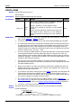
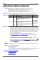
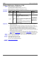
CALCulate:COMPare:DATA
Syntax
CALCulate:COMPare:DATA <data>[,(@<ch_list>)]
CALCulate:COMPare:DATA? [(@<ch_list>)]
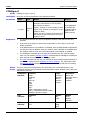
Description
Parameters
Set the alarm value of the input signal of the specified DIO channel.
Name
Type
Range
Default
<data>
Integer
8 bit: 0 to 255
16 bit: 0 to 65535
32 bit: 0 to 42,9496,7295
None
One or more channels (the DIO channels), the
rules are as follows:
<ch_list>
Explanation
Return
Format
Example
Related
commands
Channel
List
(@101): channel 01 on the module in Slot1;
(@101:103): channel 01 through 03 on the
module in Slot1;
(@101:103,301): channel 01 through 03 on
the module in Slot1 and channel 01 on the
module in Slot3.
If the parameter
is omitted, this
command will be
applied to the
whole scan list.
This command is only valid for the DIO channels on the multifunction module. The
specified DIO channels do not have to be part of the scan list.
The range of <data> depends on the bit setting of the channel. When the setting value
of <data> exceeds the range, the instrument will convert the setting value to a binary
number and then take the bit setting of the channel as the parameter value
automatically. For example, when the channel is set to 8 bit and <data> is set to 256
(the binary number is 1 0000 0000), the actual setting value is 0 (0000 0000).
After setting the alarm value using this command, you can send the
CALCulate:COMPare:STATe command enable the pattern comparison function of the
DIO channel.
A Factory Reset (the *RST command) clears the alarm value and turns off the pattern
comparison mode. An Instrument Preset (the SYSTem:PRESet command) and Card
Reset (the SYSTem:CPON command) do not clear the data and does not turn off the
pattern comparison mode.
The query returns a decimal integer. Multiple return values are separated by commas.
CALC:COMP:DATA 129,(@301)
CALCulate:COMPare:MASK
CALCulate:COMPare:STATe
CALCulate:COMPare:TYPE
2-8
M300 Programming Guide
RIGOL
Chapter 2 Command System
CALCulate:COMPare:MASK
Syntax
CALCulate:COMPare:MASK <mask>[,(@<ch_list>)]
CALCulate:COMPare:MASK? [(@<ch_list>)]
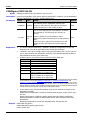
Description
Parameters
Pattern comparisons can compare just the specified bits and ignore the other bits. This
command sets the pattern of the active bits and the bits to be ignored (named the mask
value) for the pattern comparison on the specified DIO channel.
Name
<mask>
Type
Range
Default
Integer
8 bit: 0 to 255 (0000 0000 to 1111 1111)
16 bit: 0 to 65535 (0000 0000 0000 0000 to
1111 1111 1111 1111)
32 bit: 0 to 42,9496,7295 (0000 0000 0000
0000 0000 0000 0000 0000 to 1111 1111
1111 1111 1111 1111 1111 1111)
Set the active bits to 1 and the bits to be
ignored to 0.
None
One or more channels (only the DIO
channels), the rules are as follows:
<ch_list>
Explanation
Return
Format
Example
Related
commands
Channel
List
(@101): channel 01 on the module in Slot1;
(@101:103): channel 01 through 03 on the
module in Slot1;
(@101:103,301): channel 01 through 03 on
the module in Slot1 and channel 01 on the
module in Slot3;
If the parameter
is omitted, this
command will be
applied to the
whole scan list.
This command is only valid for the DIO channels on the multifunction module. The
specified DIO channels do not have to be part of the scan list.
The range of <mask> depends on the bit setting of the channel. When the setting
value of <mask> exceeds the range, the instrument will convert the setting value to a
binary number and then take the bit setting of the channel as the parameter value
automatically. For example, when the channel is set to 8 bit and <mask> is set to 256
(the binary number is 1 0000 0000), the actual setting value is 0 (0000 0000).
This command is used in conjunction with the CALCulate:COMPare:DATA command to
set the alarm value (refer to the “Example”).
A Factory Reset (the *RST command) clears the mask and turns off the pattern
comparison mode. An Instrument Preset (the SYSTem:PRESet command) and Card
Reset (the SYSTem:CPON command) does not clear the mask and does not turn off the
pattern comparison mode.
The query returns a decimal value. Multiple return values are separated by commas.
CALC:COMP:MASK 129,(@301)
/*Set the mask value to 1000 0001. The active bits are
bit7 and bit0*/
CALC:COMP:DATA 154,(@301) /*Set the alarm value to 1001 1010*/
CALC:COMP:TYPE EQU,(@301) /*The instrument generates an alarm when the input
pattern matches the alarm value*/
CALC:COMP:STAT ON,(@301)
/*Enable the pattern comparison mode. The instrument
generates an alarm when the bit7 and bit0 of the input
pattern of the channel are 1 and 0 respectively*/
CALCulate:COMPare:DATA
CALCulate:COMPare:STATe
CALCulate:COMPare:TYPE
M300 Programming Guide
2-9
RIGOL
Chapter 2 Command System
CALCulate:COMPare:STATe
Syntax
CALCulate:COMPare:STATe <state>[,(@ch_list)]
CALCulate:COMPare:STATe? [(@<ch_list>)]
Description
Parameters
This command disables or enables the pattern comparison mode on the specified digital
input channels. Once the pattern comparison mode was enabled, the instrument monitors
the digital input value of the channel, compares the digital input value with the alarm value
and generates an alarm when the digital input value is the same as or different from the
pattern defined.
Name
Type
Range
Default
<state>
Bool
{OFF|0|ON|1}
None
One or more channels (only for the DIO
channels), the rules are as follows:
<ch_list>
Explanation
Return
Format
Example
Channel
List
(@101): channel 01 on the module in Slot1;
(@101:103): channel 01 through 03 on the
module in Slot1;
(@101:103,301): channel 01 through 03 on
the module in Slot1 and channel 01 on the
module in Slot3.
If the parameter
is omitted, this
command will be
applied to the
whole scan list.
This command is only valid for the DIO channels of the multifunction module. The
specified DIO channels do not have to be part of the scan list.
A Factory Reset (the *RST command) turns off the pattern comparison mode. An
Instrument Preset (the SYSTem:PRESet command) or Card Reset (the SYSTem:CPON
command) does not turn off the pattern comparison mode.
The query returns 0 or 1. Multiple return values are separated by commas.
CALC:COMP:STAT 1,(@301)
CALC:COMP:STAT? (@301)
The query returns 1.
Related
commands
CALCulate:COMPare:DATA
CALCulate:COMPare:MASK
CALCulate:COMPare:TYPE
2-10
M300 Programming Guide
RIGOL
Chapter 2 Command System
CALCulate:COMPare:TYPE
Syntax
CALCulate:COMPare:TYPE <mode>[,(@<ch_list>)]
CALCulate:COMPare:TYPE? [(@<ch_list>)]
Description
Parameters
This command sets the pattern comparison mode for the specified digital input channels.
The instrument will generate an alarm when the digital input value is the same as or
different from the pattern defined.
Name
Type
Range
Default
<mode>
Discrete
{EQUal|NEQual}
None
One or more channels (only for the DIO
channels), the rules are as follows:
<ch_list>
Explanation
Return
Format
Example
Channel
List
(@101): channel 01 on the module in
Slot1;
(@101:103): channel 01 through 03 on
the module in Slot1;
(@101:103,301): channel 01 through 03
on the module in Slot1 and channel 01 on
the module in Slot3.
If the parameter
is omitted, this
command will
be applied to the
whole scan list.
This command is only valid for the DIO channels of MC3534 (multifunction module).
The specified DIO channels do not have to be part of the scan list.
In pattern comparison, the bits of which the mask value (set using the
CALCulate:COMPare:MASK command) are 0 will be ignored and only the bits of which
the mask value is 1 will be compared. When EQUal is selected, the instrument
generates an alarm when the input pattern monitored is the same with the alarm
value (set using the CALCulate:COMPare:DATA command). When NEQual is selected,
the instrument generates an alarm when the input pattern monitored is different from
the alarm value.
A Factory Reset (the *RST command) clears the pattern compare setting and turns
off the pattern comparison mode. An Instrument Preset (the SYSTem:PRESet
command) or Card Reset (the SYSTem:CPON command) does not clear the pattern
compare setting and does not turn off the pattern comparison mode.
The query returns EQU or NEQ. Multiple return values are separated by commas.
CALC:COMP:TYPE EQU,(@301:304)
CALC:COMP:TYPE? (@301:304)
The query returns EQU,EQU,EQU,EQU.
Related
commands
CALCulate:COMPare:DATA
CALCulate:COMPare:MASK
CALCulate:COMPare:STATe
M300 Programming Guide
2-11
RIGOL
Chapter 2 Command System
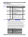
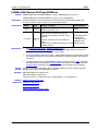
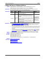
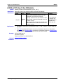
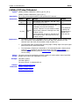
CALCulate:LIMit:LOWer
CALCulate:LIMit:UPPer
Syntax
CALCulate:LIMit:LOWer {<lo_limit>|MAX|MIN}[,(@<ch_list>)]
CALCulate:LIMit:LOWer? [(@<ch_list>)]
CALCulate:LIMit:UPPer {<hi_limit>|MAX|MIN}[,(@<ch_list>)]
CALCulate:LIMit:UPPer? [(@<ch_list>)]
Description
Parameters
Set the alarm lower and upper limits of the specified channels.
Name
<lo_limit>
Type
Numeric
Range
Default
Multiplexer channel: any numeric value
between MIN and MAX
MIN=-1.000000000E+15
MAX=+1.000000000E+15
0
TOT Channel: none
<hi_limit>
Numeric
Multiplexer channel: any numeric value
between MIN and MAX
MIN=-1.000000000E+15
MAX=+1.000000000E+15
TOT Channel: any integer between 0 and
4294967295 (232-1)
One or more channels (only for the
multiplexer channels and TOT channels), the
rules are as follows:
<ch_list>
Explanation
Return
Format
2-12
Channel
List
(@101): channel 01 on the module in Slot1;
(@101:103): channel 01 through 03 on the
module in Slot1;
(@101:103,301): channel 01 through 03 on
the module in Slot1 and channel 01 on the
module in Slot3.
0 for the
multiplexer
channel and 1
for the TOT
channel
If the parameter
is omitted, this
command will be
applied to the
whole scan list.
An error is generated if the DMM module is not installed or is disabled. You can set a
lower limit, an upper limit or both for the specified channel. The lower limit must
always be lower than or equal to the upper limit.
For the TOT channels, the channels do not have to be part of the scan list and the DMM
module is not required. You can only set the upper limit of the TOT channels.
Once you have defined the upper and lower limits using these commands, sending the
CALCulate:LIMit:LOWer:STATe and CALCulate:LIMit:UPPer:STATe command can
enable the corresponding alarm modes.
Changing the channel function and scaling parameters will turn off the alarm function
and clear the alarm limits.
When a channel is removed from the scan list, its alarm limits will not be cleared. When
it is re-added into the scan list (the channel function and scaling parameters are not
changed), the alarm setting of this channel remains unchanged.
A Factory Reset (the *RST command) clears the alarm limits and turns off the alarm
function. An Instrument Preset (the SYSTem:PRESet command) or Card Reset (the
SYSTem:CPON command) does not clear the alarm limits and does not turn off the
alarm function.
The query returns the alarm limits in scientific notation. Multiple return values are
separated by commas.
M300 Programming Guide
RIGOL
Chapter 2 Command System
Example
CALC:LIM:LOW 4.5,(@101)
CALC:LIM:LOW? (@101)
The query returns +4.500000000E+00.
You can replace LOW with UPP to set and query the upper limits of the specified channels.
Related
commands
CALCulate:LIMit:LOWer:STATe
CALCulate:LIMit:UPPer:STATe
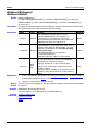
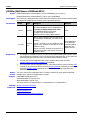
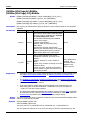
CALCulate:LIMit:LOWer:STATe
CALCulate:LIMit:UPPer:STATe
Syntax
CALCulate:LIMit:LOWer:STATe <mode>,(@<ch_list>)
CALCulate:LIMit:LOWer:STATe? (@<ch_list>)
CALCulate:LIMit:UPPer:STATe <mode>,(@<ch_list>)
CALCulate:LIMit:UPPer:STATe? (@<ch_list>)
Description
Parameters
Disable or enable the lower and upper alarm limits of the specified channels to set the
alarm modes of the specified channels. The combinations of the upper limit and lower limit
states correspond to the four alarm modes (NONE, LO, HI, HI + LO).
Name
Type
Range
Default
<mode>
Bool
{OFF|0|ON|1}
OFF
One or more channels (only for the
multiplexer channels and TOT channels), the
rules are as follows:
<ch_list>
Explanation
Return
Format
Example
Related
commands
Channel
List
(@101): channel 01 on the module in Slot1;
(@101:103): channel 01 through 03 on the
module in Slot1;
(@101:103,301): channel 01 through 03 on
the module in Slot1 and channel 01 on the
module in Slot3.
If the parameter
is omitted, this
command will
be applied to
the whole scan
list.
An error is generated if the DMM module is not installed or is disabled. You can enable
the alarm lower limit, alarm upper limit or both for the specified channel.
For the TOT channels, the channels do not have to be part of the scan list and the
DMM module is not required. You can only set the upper limit of the TOT channels.
A Factory Reset (the *RST command) clears the alarm limits and turns off the alarm
function. An Instrument Preset (the SYSTem:PRESet command) or Card Reset (the
SYSTem:CPON command) does not clear the alarm limits and does not turn off the
alarm function.
The query returns 0 or 1. Multiple return values are separated by commas.
CALC:LIM:LOW:STAT ON,(@101)
CALC:LIM:LOW:STAT? (@101)
The query returns 1.
You can replace LOW with UPP to set or query the upper limits status.
CALCulate:LIMit:LOWer
CALCulate:LIMit:UPPer
M300 Programming Guide
2-13
RIGOL
Chapter 2 Command System
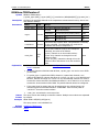
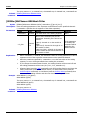
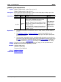
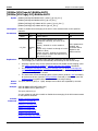
CALCulate:SCALe:SQUare
CALCulate:SCALe:GAIN
CALCulate:SCALe:OFFSet
CALCulate:SCALe:CONStant
Syntax
CALCulate:SCALe:SQUare {<square>|MAX|MIN}[,(@<ch_list>)]
CALCulate:SCALe:SQUare? [(@<ch_list>)]
CALCulate:SCALe:GAIN {<gain>|MAX|MIN}[,(@<ch_list>)]
CALCulate:SCALe:GAIN? [(@<ch_list>)]
CALCulate:SCALe:OFFSet {<offset>|MAX|MIN}[,(@<ch_list>)]
CALCulate:SCALe:OFFSet? [(@<ch_list>)]
CALCulate:SCALe:CONStant {<constant>|MAX|MIN}[,(@<ch_list>)]
CALCulate:SCALe:CONStant? [(@<ch_list>)]
Description
Parameters
Set the scaling coefficients (SQUare (A), GAIN (B), OFFSet (x1) and CONStant (C)) of
the specified channels.
Name
Type
Range of Values
Default Value
Numeric
Any numeric value between MIN and MAX
MIN=-1.000000000E+15
MAX=+1.000000000E+15
<square>
<gain>
<offset>
0
<constant>
Explanation
0
0
One or more channels (only for the
multiplexer channels), the rules are as
follows:
<ch_list>
1
Channel
List
(@101): channel 01 on the module in
Slot1;
(@101:103): channel 01 through 03 on the
module in Slot1;
(@101:103,301): channel 01 through 03
on the module in Slot1 and channel 01 on
the module in Slot3.
If the parameter
is omitted, this
command will be
applied to the
whole scan list.
The formula of the scaling function is:
Scaled Reading = SQUare×(Reading- OFFSet)2+GAIN×(Reading- OFFSet) +
CONStant
2-14
An error is generated if the DMM module is not installed or is disabled (refer to the
INSTrument:DMM command).
When the channel measurement function or the remperature sensor type is changed,
the scaling function will be turned off and the scaling coefficients will be reset (A=0,
B=1, C=0, x1=0).
Configuring the scaling coefficients will turn off the alarm function and clear the alarm
parameters. Please configure the scaling parameters before configuring the alarm
parameters.
A Factory Reset (the *RST command) turns off the scaling function and clears the
scaling coefficients (A=0, B=1, C=0, x1=0). An Instrument Preset (the
SYSTem:PRESet command) or Card Reset (the SYSTem:CPON command) does not
turn off the scaling function and does not clear the scaling coefficients.
M300 Programming Guide
RIGOL
Chapter 2 Command System
Return
Format
Example
The query returns the coefficients in scientific notation. Multiple return values are
separated by commas.
CALC:SCAL:SQU 10,(@101)
CALC:SCAL:SQU? (@101)
CALC:SCAL:GAIN 25,(@101)
CALC:SCAL:GAIN? (@101)
CALC:SCAL:OFFS 15,(@101)
CALC:SCAL:OFFS? (@101)
CALC:SCAL:CONS 5,(@101)
CALC:SCAL:CONS? (@101)
The query returns
+1.000000000E+01
+2.500000000E+01
+1.500000000E+01
+5.000000000E+00
Related
commands
CALCulate:SCALe:STATe
CALCulate:SCALe:UNIT
CALCulate:SCALe:OFFSet:NULL
CALCulate:SCALe:OFFSet:NULL
Syntax
Description
Parameters
CALCulate:SCALe:OFFSet:NULL [(@<ch_list>)]
Set OFFSet (x1) to the measurement value.
Name
Type
Range
One or more channels (only for the
multiplexer channels), the rules are as
follows:
<ch_list>
Example
Channel
List
(@101): channel 01 on the module in
Slot1;
(@101:103): channel 01 through 03 on the
module in Slot1;
(@101:103,301): channel 01 through 03
on the module in Slot1 and channel 01 on
the module in Slot3.
Default
If the
parameter is
omitted, this
command will
be applied to
the whole
scan list.
CALC:SCAL:OFFS 2.5,(@101)
CALC:SCAL:OFFS? (@101)
CALC:SCAL:OFFS:NULL (@101)
CALC:SCAL:OFFS? (@101)
The query returns
+2.500000000E+00
-1.626940834E-03
Related
commands
CALCulate:SCALe:SQUare
CALCulate:SCALe:STATe
CALCulate:SCALe:GAIN
CALCulate:SCALe:OFFSet
CALCulate:SCALe:CONStant
CALCulate:SCALe:UNIT
M300 Programming Guide
2-15
RIGOL
Chapter 2 Command System
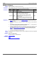
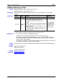
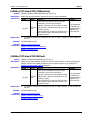
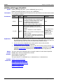
CALCulate:SCALe:STATe
Syntax
CALCulate:SCALe:STATe <state>[,(@<ch_list>)]
CALCulate:SCALe:STATe? [(@<ch_list>)]
Description
Parameters
Disable or enable the scaling function of the specified channels.
Name
Type
Range
Default
<state>
Bool
{OFF|0|ON|1}
OFF
One or more channels (only for the
multiplexer channels), the rules are as
follows:
<ch_list>
Explanation
Channel
List
(@101): channel 01 on the module in Slot1;
(@101:103): channel 01 through 03 on the
module in Slot1;
(@101:103,301): channel 01 through 03 on
the module in Slot1 and channel 01 on the
module in Slot3.
If the parameter
is omitted, this
command will be
applied to the
whole scan list.
The formula of the scaling function is:
Scaled Reading = SQUare×(Reading- OFFSet)2+GAIN×(Reading- OFFSet) +
CONStant
Return
Format
Example
The scaling function is only applicable to the multiplexer channels. To use this function,
the DMM module muat be installed and enabled.
When the channel measurement function or measurement parameters is changed, the
scaling function will be turned off and the scaling coefficients will be reset (A=0, B=1,
C=0, x1=0).
Configuring the scaling coefficients will turn off the alarm function and clear the alarm
parameters. Please configure the scaling parameters before configuring the alarm
parameters.
A Factory Reset (the *RST command) turns off the scaling function and clears the
scaling coefficients. An Instrument Preset (the SYSTem:PRESet command) or Card
Reset (the SYSTem:CPON command) does not turn off the scaling function and does
not clear the scaling coefficients.
The query returns 0 or 1. Multiple return values are separated by commas.
CALC:SCAL:STAT ON,(@101,102)
CALC:SCAL:STAT? (@101,102)
The query returns 1,1.
Related
commands
CALCulate:SCALe:SQUare
CALCulate:SCALe:GAIN
CALCulate:SCALe:OFFSet
CALCulate:SCALe:CONStant
CALCulate:SCALe:UNIT
CALCulate:SCALe:OFFSet:NULL
2-16
M300 Programming Guide
RIGOL
Chapter 2 Command System
CALCulate:SCALe:UNIT
Syntax
CALCulate:SCALe:UNIT <quoted_string>[,(@<ch_list>)]
CALCulate:SCALe:UNIT? [(@<ch_list>)]
Description
Parameters
Specify the uint of the scaled readings of the specified channels. It will affect the unit of the
readings when storing the measurement data.
Name
<quoted_string>
Type
Range
Default
Discrete
{K|#C|#F|ASCII String}
Wherein, "#" represents the degree
symbol (°); the ASCII string is
enclosed in double quotation marks
and can not exceeds three characters
(it can contain English
uppercase/lowercase letters (A-Z, a-z)
or numbers (0-9). The first character
can not be a number).
The default
unit of the
current
function[1].
One or more channels (only for the
multiplexer channels), the rules are as
follows:
<ch_list>
Channel
List
(@101): channel 01 on the module in
Slot1;
(@101:103): channel 01 through 03
on the module in Slot1;
(@101:103,301): channel 01 through
03 on the module in Slot1 and channel
01 on the module in Slot3.
If the
parameter is
omitted, this
command will
be applied to
the whole scan
list.
Note[1]: For the voltage measurement, the default unit is “V”. For the current measurement, the
default unit is “A”. For the resistance measurement, the default unit is “Ω”. For the frequency
measurement, the default unit is “Hz”. For the period measurement, the default unit is “s”. For the
temperature measurement, the default unit is “°C”.
Explanation
Return
Format
Example
If you set the unit of the scaled readings to °C, °F, or K using this command, the unit of
the temperature measurement will not be affected (refer to the UNIT Command
Subsystem).
If the measurement function of the specified channel is Anysensor, the unit of the
scaling is not allowed to set and an error will be generated when sending this
command.
The commands in the CONFigure Command Subsystem and MEASure Command
Subsystem will automatically revert the unit to the default units for the function.
The scaling unit is used when displaying and storing of the scaling readings and has no
effect on the measurement units.
A Factory Reset (the *RST command) turns off the scaling function and clears the units
of the scaling readings (the units are restored to the default units for the function). An
Instrument Preset (the SYSTem:PRESet command) or Card Reset (the SYSTem:CPON
command) does not turn off the scaling function and does not clear the units of the
scaling readings.
The query returns ”K”, ”#C”, ”#F” or ASCII strings enclosed in double quotation marks for
the specified channels. Multiple return values are separated by commas.
CALC:SCAL:UNIT “PSI”,(@101,102)
CALC:SCAL:UNIT? (@101,102)
The query returns ”PSI”,”PSI”.
M300 Programming Guide
2-17
RIGOL
Related
commands
Chapter 2 Command System
CALCulate:SCALe:SQUare
CALCulate:SCALe:GAIN
CALCulate:SCALe:OFFSet
CALCulate:SCALe:CONStant
CALCulate:SCALe:STATe
CALCulate:SCALe:OFFSet:NULL
2-18
M300 Programming Guide
Chapter 2 Command System
RIGOL
CONFigure Command Subsystem
The CONFigure commands are used to configure the measurement function of the specified channel with
the specified parameters, but do not start the scan. After finishing the configuration using the CONFigure
commands, you can send the INITiate command to start the scan and then send the READ? command to
read the measurment value.
CONFigure?
CONFigure:ANYSensor
CONFigure:COPY:CH:CH
CONFigure:COPY:CH:SLOT
CONFigure:COPY:SLOT:SLOT
CONFigure:CURRent:AC
CONFigure:CURRent[:DC]
CONFigure:DIGital:BYTE
CONFigure:DIGital:DWORd
CONFigure:DIGital:WORD
CONFigure:FREQuency
CONFigure:PERiod
CONFigure:FRESistance
CONFigure:RESistance
CONFigure:TEMPerature
CONFigure:TOTalize
CONFigure:VOLTage:AC
CONFigure:VOLTage[:DC]
M300 Programming Guide
2-19
RIGOL
Chapter 2 Command System
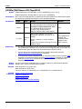
CONFigure?
Syntax
Description
Parameters
CONFigure? [(@<ch_list>)]
Query the current configuration of the specified channels.
Name
Type
Range
Default
One or more channels (for the multiplexer
channels, DIO channels or TOT channel),
the rules are as follows:
<ch_list>
Explanation
Return
Format
2-20
Channel
List
(@101): channel 01 on the module in Slot1;
(@101:103): channel 01 through 03 on the
module in Slot1;
(@101:103,301): channel 01 through 03 on
the module in Slot1 and channel 01 on the
module in Slot3.
If the parameter
is omitted, this
command will be
applied to the
whole scan list.
The specified channels can only be multiplexer channels, DIO channels and TOT
channels.
If the scan list is empty, the instrument will generate an error when you send the
CONF? command.
If the DMM module is not installed or is disabled, then no DMM-related configurations
are allowed on the multiplexer channels. However, scan is allowed on the digital input
and totalizer channels even when the DMM module is not installed or enabled.
The CONFigure command does not place the instrument into the “wait-for-trigger”
state. You can send the INITiate or READ? command with the CONFigure command to
place the instrument into the “wait-for-trigger” state.
The *RST command will clear the scan list and set all the measurement parameters to
their factory settings (refer to Appendix A: Factory settings). The Instrument Preset
(the SYSTem:PRESet command) will not clear the scan list but will clear the reading
memory.
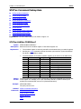
The query returns the configurations (for the details, refer to the table below) of the
specified channels in string enclosed in double quotation marks. Multiple return values are
separated by commas.
multiplexer
channels
Function:
CURR
CURR:AC
VOLT
VOLT:AC
RES
FRES
FREQ
PER
TEMP <Temperature sensor
type>,<Temperature Sensor Model>
SENSOR <Anysensor type>
DIO
channels
Function:
DIG
TOT
channels
Function:
TOT
Range
Return the
specified
value in
scientific
notation
Resolution
Return the
specified value in
scientific
notation
Status:
Width:
BYTE
WORD
DWORD
Mode:
READ
RRES
--
INP
OUTP
M300 Programming Guide
RIGOL
Chapter 2 Command System
Example
CONF? (@301,305,401)
The query returns
"DIG OUTP BYTE","TOT RRES","VOLT +2.000000E+01,+6.000000E-05"
Related
command
CONFigure Command Subsystem
CONFigure:ANYSensor
Syntax
Description
Parameters
CONFigure:ANYSensor [{<type>|DEF},](@<scan_list>)
Configure the specified channel as the specified anysensor measurement function, but do
not start the scan.
Name
Type
Range
Default
<type>
Discrete
{VOLT|CURR|RES|FRES|FREQ}
VOLT or
CURR[1]
One or more channels (only for the multiplexer
channels), the rules are as follows:
<scan_list>
Scan
List
(@101): channel 01 on the module in Slot1;
(@101:103): channel 01 through 03 on the
module in Slot1;
(@101:103,301): channel 01 to channel 03 on the
module in Slot1 and channel 01 on the module in
Slot3.
None
Note[1]: When <type> is set to DEF or is omitted, for channels 21 to 24 of MC3324, the anysensor
type is set to DCI; for other multiplexer channels, the anysensor type is set to DCV.
Explanation
<scan_list> can only be the multiplexer channels.
For channels 21 to 24 of MC3324, <type> can only be CURR;
For all the channels of MC3164 and MC3264, <type> can not be FRES and CURR;
For other multiplexer channels, <type> can not be CURR.
Example
<scan_list> overwrites the current scan list.
CONF:ANYS RES,(@101:110)
M300 Programming Guide
2-21
RIGOL
Chapter 2 Command System
CONFigure:COPY:CH:CH
Syntax
Description
Parameters
CONFigure:COPY:CH:CH (@<channel>),(@<ch_list>)
Copy the configuration of the source channel (specified by <channel>) to the destination
channels (specified by <ch_list>), namely channel copy.
Name
<channel>
Type
Range
Default
channel
One channel (for the multiplexer channel, DIO
channel or TOT channel), the rules are as follows:
None
(@101):channel 01 on the module in Slot1;
One or more channels (for the multiplexer channels,
DIO channels or TOT channel), the rules are as
follows:
<ch_list>
Explanation
Channel
List
(@101): channel 01 on the module in Slot1;
(@101:103): channel 01 through 03 on the module in
Slot1;
(@101:103,301): channel 01 to channel 03 on the
module in Slot1 and channel 01 on the module in
Slot3;
None
The source channel specified by <channel> should be configured in the scan list.
Otherwise, an error will be generated when sending this command.
<channel> can only be a single channel (the source channel) and <ch_list> can be
one or more channels (the destination channels). The channels specified by both of
the parameters must be of the same type.
Channel copy are only allowed among channels of the same type.
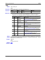
Module
Channel Type
MC3120
All the channels are of the same type.
MC3132
All the channels are of the same type.
MC3164
All the channels are of the same type.
MC3232
All the channels are of the same type.
MC3264
All the channels are of the same type.
MC3324
Type 1: channel 01 to channel 20
Type 2: channel 21 to channel 24
MC3534
Type 1: channel 01 to channel 04[1]
Type 2: channel 05 to channel 06
Type 3: channel 07 to channel 08
Note[1]: The channel copy status of channel 01 to channel 04, is determined by the bits setting
of the channels (refer to the CONFigure:DIGital:BYTE, CONFigure:DIGital:WORD and
CONFigure:DIGital:DWORd commands). When the bits is set to 8-bit, the channel copy can be
performed among all the four channels. When the bits is set to 16-bit, the channel copy is only
allowed between channel 01 and channel 03. When the bits is set to 32-bit, the channel copy is
only allowed between channel 01 from different MC3534 modules.
Example
2-22
In the channel copy, the following settings of the source channel are copied to the
destination channels.
Measurement Configuration: include the measurement function, range, sensor type
and etc.;
Scaling Configuration: include the scaling switch status and scaling coefficients;
Alarm Configuration: include the alarm switch status, alarm channel number and
alarm limits;
Advanced Configuration: include the integration time, AC filter and etc.
CONF:VOLT:DC (@101)
CONF:COPY:CH:CH (@101),(@102:120)
CONF? (@102,110)
M300 Programming Guide
RIGOL
Chapter 2 Command System
The query returns
"VOLT +2.000000E+01,+6.000000E-06","VOLT +2.000000E+01,+6.000000E-06".
Related
command
CONFigure Command Subsystem
CONFigure:COPY:CH:SLOT
Syntax
Description
Parameters
Explanation
Example
CONFigure:COPY:CH:SLOT (@<channel>),<slot>
Copy the configuration of the source channel (specified by <channel>) to all the channels
(of which the type is the same with that of the source channel) of the destination module
(specified by <slot>), namely extended copy.
Name
Type
Range
Default
<channel>
Channel
One channel (for the multiplexer channel , DIO
channel or TOT channel), the rules are as
follows: (@101): channel 01 on the module in
Slot1;
None
<slot>
Discrete
100/200/300/400/500: the slot number of the
destination module.
None
The source channel specified by <channel> should be configured in scan list.
Otherwise, an error will be generated when sending this command.
<channel> can only be a single channel (namely the source channel). <slot> defines
the destination module which must be of the same type with the module of the source
channel.
In the extended copy, the following settings of the source channel are automatically
copied to the destination module.
Measurement Configuration: include the measurement function, range, sensor type
and etc.;
Scaling Configuration: include the scaling status and scaling coefficients;
Alarm Configuration: include the alarm status, alarm channel number and alarm limits;
Advanced Configuration: include the integration time, AC filter and etc.
It is assumed that both Slot1 and Slot2 are inserted with the MC3132 module.
CONF:VOLT:DC (@101)
CONF:COPY:CH:SLOT (@101),200
CONF? (@202,210)
The query returns
"VOLT +2.000000E+01,+6.000000E-06","VOLT +2.000000E+01,+6.000000E-06".
Related
command
CONFigure Command Subsystem
M300 Programming Guide
2-23
RIGOL
Chapter 2 Command System
CONFigure:COPY:SLOT:SLOT
Syntax
Description
Parameters
Explanation
Example
CONFigure:COPY:SLOT:SLOT <slot1>,<slot2>
Copy the configuration of the source module (specified by <slot1>) to the destination
module (specified by <slot2>), namely module copy.
Name
Type
Range
Default
<slot1>
Discrete
100/200/300/400/500: the slot number of the source
module.
None
<slot2>
Discrete
100/200/300/400/500: the slot number of the
destination module.
None
<slot1> defines the source module and <slot2> defines the destination module. The
type of the two modules must be the same.
In the module copy, the configurations of all the channels of the source module are
automatically copied to the channels of the destination module.
It is assumed that both Slot1 and Slot2 are inserted with the MC3132 module.
CONF:VOLT:DC (@101:110)
CONF:COPY:SLOT:SLOT 100,200
CONF? (@101,201)
The query returns
"VOLT +2.000000E+01,+6.000000E-06","VOLT +2.000000E+01,+6.000000E-06".
Related
command
2-24
CONFigure Command Subsystem
M300 Programming Guide
RIGOL
Chapter 2 Command System
CONFigure:CURRent:AC
Syntax
Description
Parameters
CONFigure:CURRent:AC
[{<range>|AUTO|MIN|MAX|DEF}[,{<resolution>|MIN|MAX|DEF}],](@<scan_list>)
Configure the specified channels to the ACI measurement function with the specified
range and resolution, but do not initiate the scan.
Name
Type
Range
Default
<range>
Numeric
Any numeric value between MIN and MAX. The
final range is decided by the “Principle of setting
with greater value”.
The standard values of the range:
{200μA|2mA|20mA|200mA|1A}
Wherein, MIN=200μA, MAX=1A, DEF=AUTO.
AUTO
<resolution>
Numeric
Can receive any numeric value, but the resolution is fixed at
61/2 digits.
One or more channels (only for channel 21 to
channel 24 of MC3324), the rules are as follows:
<scan_list>
Explanation
Example
Scan
List
(@121): channel 21 on the module in Slot1;
(@121:123): channel 21 through 23 on the
module in Slot1;
(@121:123,321): channel 21 to 23 on the module
in Slot1 and channel 21 on the module in Slot3.
None
This command is only applicable to channel 21 to channel 24 of MC3324. When
<scan_list> is set to other channels, an error will be generated.
The CONFigure command does not place the instrument into the “wait-for-trigger”
state. You can send the INITiate or READ? command with the CONFigure command
to place the instrument into the “wait-for-trigger” state.
You can select autoranging to allow the instrument to automatically select a proper
measurement range or you can select a fixed range to set the range manually.
Autoranging rule: for signals under test that is between 10%*Range and
110%*Range, the instrument automatically selects Range as the current range.
When <range> is set to DEF or AUTO, an error will be generated if <resolution> is
set to a numeric value, because the instrument cannot calculate the integration time
accurately (especially when the input signal is continuously changing) when the
autoranging is combined with a numeric resolution. If your application requires
autoranging, be sure to specify "DEF" for <resolution> or omit the parameter.
If the input signal is greater than can be measured on the selected range, the
instrument gives an overload indication: "OVERLOAD" from the front panel or
"±9.9E+37" from the remote interface.
The *RST command will clear the scan list and set all the measurement parameters
to their factory settings. The Instrument Preset (the SYSTem:PRESet command) will
not clear the scan list; however, this command will clear the data in the reading
memory.
<scan_list> overwrites the current scan list.
CONF:CURR:AC MAX,DEF,(@121)
CONF?
The query returns "CURR:AC +1.000000E+00,+1.000000E-04".
M300 Programming Guide
2-25
RIGOL
Related
commands
Chapter 2 Command System
CONFigure?
INITiate
READ?
2-26
M300 Programming Guide
RIGOL
Chapter 2 Command System
CONFigure:CURRent[:DC]
Syntax
Description
Parameters
CONFigure:CURRent[:DC]
[{<range>|AUTO|MIN|MAX|DEF}[,{<resolution>|MIN|MAX|DEF}],](@<scan_list>)
Configure the specified channels to the DCI measurement function with the specified range
and resolution, but do not initiate the scan.
Name
<range>
<resolution>
Type
Range
Default
Numeric
Any numeric value between MIN and MAX. The
final range is decided by the “Principle of setting
with greater value”.
The standard values of the range:
{200μA|2mA|20mA|200mA|1A}
Wherein, MIN=200μA, MAX=1A, DEF=AUTO.
AUTO
Numeric
Can receive any numeric value between
0.03ppm×<range> and 3ppm×<range>. The
final resolution is decided by the “Principle of
setting with smaller value”.
The standard values of the resolution: refer to
the “Explanation”.
0.3ppm×
<range>
One or more channels (only for channel 21 to
channel 24 of MC3324), the rules are as follows:
<scan_list>
Explanation
Scan
List
(@121): channel 21 on the module in Slot1;
(@121:123): channel 21 through 23 on the
module in Slot1;
(@121:123,321): channel 21 through 23 on the
module in Slot1 and channel 21 on the module in
Slot3.
None
This command is only applicable to channel 21 to channel 24 of MC3324. When
<scan_list> is set to other channels, an error will be generated.
The CONFigure command does not place the instrument into the “wait-for-trigger”
state. You can send the INITiate or READ? command with the CONFigure command to
place the instrument into the “wait-for-trigger” state.
You can select autoranging to allow the instrument to automatically select a proper
measurement range or you can select a fixed range to set the range manually.
Autoranging rule: for signals under test that is between 10%*Range and
110%*Range, the instrument automatically selects Range as the current range.
When <range> is set to DEF or AUTO, an error will be generated if <resolution> is set
to a numeric value, because the instrument cannot calculate the integration time
accurately (especially when the input signal is continuously changing) when the
autoranging is combined with a numeric resolution. If your application requires
autoranging, be sure to specify "DEF" for <resolution> or omit the parameter.
<resolution> is related to the current integration time and range (<range>). The
relations are as shown in the table below.
Integration Time
Resolution
0.02PLC
3ppm× <range> (MAX)
0.2PLC
0.7ppm× <range>
1PLC
0.3ppm× <range> (DEF)
2PLC
0.2ppm× <range>
10PLC
0.1ppm× <range>
20PLC
0.06ppm× <range>
M300 Programming Guide
2-27
RIGOL
Example
Related
commands
Chapter 2 Command System
100PLC
0.035ppm× <range>
200PLC
0.03ppm× <range> (MIN)
If the input signal is greater than can be measured on the selected range, the
instrument gives an overload indication: "OVERLOAD" from the front panel or
"±9.9E+37" from the remote interface.
The *RST command will clear the scan list and set all the measurement parameters to
their factory settings. The Instrument Preset (the SYSTem:PRESet command) will not
clear the scan list; however, this command will clear the data in the reading memory.
<scan_list> overwrites the current scan list.
CONF:CURR:DC AUTO,DEF,(@121)
CONFigure?
INITiate
READ?
2-28
M300 Programming Guide
RIGOL
Chapter 2 Command System
CONFigure:DIGital:BYTE
CONFigure:DIGital:DWORd
CONFigure:DIGital:WORD
Syntax
CONFigure:DIGital:BYTE (@<scan_list>)
CONFigure:DIGital:DWORd (@<scan_list>)
CONFigure:DIGital:WORD (@<scan_list>)
Description
Parameters
Set the bits of the DIO channels when they are used as the digital input terminals. BYTE
represents 8-bit, WORd represents 16-bit and DWORd represents 32-bit. This command
does not initiate the scan.
Name
Type
Range
Default
One or more channels (only for channel 01 to channel
04 of MC3534), the rules are as follows:
<scan_list>
Explanation
Example
Scan
List
(@101): channel 01 on the module in Slot1;
(@101:103): channel 01 through 03 on the module in
Slot1;
(@101:103,301): channel 01 to channel 03 on the
module in Slot1 and channel 01 on the module in Slot3;
None
The digital input channels are usually numbered as "S01" to "S04"; wherein, S is the
number of the slot of the multifunction module.
The CONFigure:DIGital:BYTE (@<scan_list>) command is applicable to S01 to S04.
The CONFigure:DIGital:WORD (@<scan_list>) command is only applicable to S01 and
S03. At this point, S01 (LSB) and S02 (MSB) as well as S03 (LSB) and S04 (MSB) are
configured as two 16-bit digital input terminals.
The CONFigure:DIGital: DWORd (@<scan_list>) command is only applicable to S01.
At this point, S01 (LSB), S02, S03 and S04 (MSB) are configured as a 32-bit digital
input terminal.
The *RSTcommand will clear the scan list and set all the measurement parameters to
their factory settings. The Instrument Preset (the SYSTem:PRESet command) will not
clear the scan list; however, this command will clear the data in the reading memory.
<scan_list> overwrites the current scan list.
CONF:DIG:BYTE (@201:204)
M300 Programming Guide
2-29
RIGOL
Chapter 2 Command System
CONFigure:FREQuency
CONFigure:PERiod
Syntax
CONFigure:FREQuency
[{<range>|AUTO|MIN|MAX|DEF}[,{<resolution>|MIN|MAX|DEF}],](@<scan_list>)
CONFigure:PERiod
[{<range>|AUTO|MIN|MAX|DEF}[,{<resolution>|MIN|MAX|DEF}],](@<scan_list>)
Description
Parameters
Configure the specified channels to the frequency or period measurement function with the
specified gate time, but do not initiate the scan.
Name
<range>
<resolution>
Type
Range
Default
Numeric
Any numeric value. This parameter is unnecessary
for the frequency and period measurements, the
instrument only receives the parameter but does
not respond to it.
AUTO
Numeric
Any numeric value between MIN and MAX. The final
gate time is decided by the “Principle of setting
with greater value”.
The standard values of the gate time:
{1ms|10ms|100ms|1s}
Wherein, MIN=1ms, MAX=1s, DEF=100ms.
100ms
One or more channels (only for the multiplexer
channels), the rules are as follows:
<scan_list>
Explanation
Example
2-30
Scan
List
(@101): channel 01 on the module in Slot1;
(@101:103): channel 01 to channel 03 on the
module in Slot1;
(@101:103,301): channel 01 to channel 03 on the
module in Slot1 and channel 01 on the module in
Slot3;
None
If the input signal is greater than can be measured on the selected range, the
instrument gives an overload indication: "OVERLOAD" from the front panel or
"±9.9E+37" from the remote interface.
The *RST command will clear the scan list and set all the measurement parameters to
their factory settings. The Instrument Preset (the SYSTem:PRESet command) will not
clear the scan list; however, this command will clear the data in the reading memory.
<scan_list> overwrites the current scan list.
CONF:FREQ MAX,DEF,(@101)
M300 Programming Guide
RIGOL
Chapter 2 Command System
CONFigure:FRESistance
CONFigure:RESistance
Syntax
CONFigure:FRESistance
[{<range>|AUTO|MIN|MAX|DEF}[,{<resolution>|MIN|MAX|DEF}],](@<scan_list>)
CONFigure:RESistance
[{<range>|AUTO|MIN|MAX|DEF}[,{<resolution>|MIN|MAX|DEF}],](@<scan_list>)
Description
Parameters
Configure the specified channels to the 2-wire resistance or 4-wire resistance
measurement function with the specified range and resolution, but do not initiate the
scan.
Name
<range>
<resolution>
Type
Range
Default
Numeric
Any numeric value between MIN and MAX.
The final range is decided by the “Principle of
setting with greater value”.
The standard values of the range:
{200Ω|2kΩ|20kΩ|200kΩ|1MΩ|10MΩ|100MΩ}
Wherein, MIN=200Ω, MAX=100MΩ,
DEF=AUTO.
AUTO
Numeric
Any numeric value between
0.03ppm×<range> and 3ppm×<range>. The
final resolution is decided by the “Principle of
setting with smaller value”.
The standard values of the resolution: refer to
the “Explanation”.
0.3ppm×
<range>
One or more channels (only for the
multiplexer channels), the rules are as
follows:
<scan_list>
Explanation
Scan
List
(@101) :channel 01 on the module in Slot1;
(@101:103): channel 01 through 03 on the
module in Slot1;
(@101:103,301): channel 01 through 03 on
the module in Slot1 and channel 01 on the
module in Slot3;
None
For MC3164 and MC3264, the 4-wire resistance measurement function is not
supported.
For the 4-wire resistance measurement function, channel n is paired with channel
n+16 (MC3132 and MC3232, wherein the range of n is from 1 to 16) or n+10
(MC3324 and MC3120, wherein the range of n is from 1 to 10) automatically. Channel
n is used to connect the source terminal of the DMM and channel n+16 or channel
n+10 is used to connect the sense terminal of the DMM. The paired channels cannot
be configured.
<range> is used to set the range. You can select autoranging to allow the instrument
to automatically select a proper measurement range or you can select a fixed range
to set the range manually.
Autoranging rule: for signals under test that is between 10%*Range and
110%*Range, the instrument automatically selects Range as the current range.
When <range> is set to DEF or AUTO, an error will be generated if <resolution> is
set to a numeric value, because the instrument cannot calculate the integration time
accurately (especially when the input signal is continuously changing) when the
autoranging is combined with a numeric resolution. If your application requires
autoranging, be sure to specify "DEF" for <resolution> or omit the parameter.
M300 Programming Guide
2-31
RIGOL
Chapter 2 Command System
Example
Related
commands
<resolution> is related to the current integration time and range (<range>). The
relations are as shown in the table below.
Integration Time
Resolution
0.02PLC
3ppm× <range> (MAX)
0.2PLC
0.7ppm× <range>
1PLC
0.3ppm× <range> (DEF)
2PLC
0.2ppm× <range>
10PLC
0.1ppm× <range>
20PLC
0.06ppm× <range>
100PLC
0.035ppm× <range>
200PLC
0.03ppm× <range> (MIN)
If the input signal is greater than can be measured on the selected range, the
instrument gives an overload indication: "OVERLOAD" from the front panel or
"±9.9E+37" from the remote interface.
The *RST command will clear the scan list and set all the measurement parameters to
their factory settings. The Instrument Preset (the SYSTem:PRESet command) will not
clear the scan list; however, this command will clear the data in the reading memory.
<scan_list> overwrites the current scan list.
CONFigure:RES AUTO,DEF,(@101)
CONFigure?
INITiate
READ?
2-32
M300 Programming Guide
RIGOL
Chapter 2 Command System
CONFigure:TEMPerature
Syntax
Description
Parameters
CONFigure:TEMPerature
{<probe_type>|DEF},{<type>|DEF}[,1[,{<resolution>|MIN|MAX|DEF}]],(@<scan_list>)
Configure the specified channels to the temperature measurement function, but do not
initiate the scan.
Name
Type
Range
Default
<probe_type>
Discrete
{TCouple|THERmistor|RTD|FRTD}
TC
TCouple
{B|E|J|K|N|R|S|T}
J
THERmistor
{2252|3000|5000|10000|30000}
5000
RTD
{85|89|91|92}
85
FRTD
{85|89|91|92}
85
<type>
<resolution>
Discrete
Numeric
Can receive any numeric value. This parameter is unessary
for the command. The instrument only receives the
parameter but does not respond to it.
One or more channels (only for the multiplexer
channels), the rules are as follows:
<scan_list>
Explanation
Example
Related
commands
Scan
List
(@101): channel 01 on the module in Slot1;
(@101:103): channel 01 through 03 on the
module in Slot1;
(@101:103,301): channel 01 through 03 on the
module in Slot1 and channel 01 on the module in
Slot3.
None
For all the channels of MC3164 and MC3264, <probe_type> can not be set to FRTD
(4-wire RTD).
If <probe_type> is specified as FRTD, channel n is paired with channel n+16
(MC3132 and MC3232, wherein the range of n is from 1 to 16) or n+10 (MC3324 and
MC3120, wherein the range of n is from 1 to 10) automatically. Channel n is used to
connect the source terminal of the DMM and channel n+16 or channel n+10 is used to
connect the sense terminal of the DMM. The paired channels cannot be configured.
For the temperature measurements, the instrument selects the range internally and
you do not need to set the range. Make sure that the command contains "1" (before
<resolution>).
If the input signal is greater than can be measured on the selected range (manual
ranging), the instrument gives an overload indication: "OVERLOAD" from the front
panel or "±9.9E+37" from the remote interface.
The *RST command will clear the scan list and set all the measurement parameters to
their factory settings. The Instrument Preset (the SYSTem:PRESet command) will not
clear the scan list; however, this command will clear the data in the reading memory.
<scan_list> overwrites the current scan list.
CONF:TEMP TC,B,1,DEF,(@101)
CONFigure?
INITiate
READ?
M300 Programming Guide
2-33
RIGOL
Chapter 2 Command System
CONFigure:TOTalize
Syntax
Description
Parameters
CONFigure:TOTalize [<mode>],(@<scan_list>)
Set the reading mode of the TOT channel of the specified channels. This command does
not initiate the scan.
Name
Type
Range
Default
<mode>
Discrete
{READ|RRESet}
READ
One or more channels (only for the TOT channels),
the rules are as follows:
<scan_list>
Explanation
Example
Related
commands
Scan
List
(@105): channel 05 on the module in Slot1;
(@105:108): channel 05 through 08 on the
module in Slot1;
(@105:108,305): channel 05 through 08 on the
module in Slot1 and channel 05 on the module in
Slot3.
None
The totalizer channels are usually numbered as "S05" to "S08"; wherein, S is the
number of the slot.
<mode> Is used to set the reading mode of the TOT channels. When READ is
selected, the instrument only reads the readings but does not reset the count. When
PRESet is selected, the instrument reads the readings and reset the count (namely,
Read and Reset).
The maximum count of each TOT channel is 42,9496,7295 (232 - 1). The count rolls
over to 0 after reaching the maximum allowed value.
Selecting the RRESet mode performs a synchronized read and reset operation on the
specified totalizer channels. If you were to use discrete commands, such as the
READ? and [SENSe:]TOTalize:CLEar:IMMediate commands, you would likely lose
counts occurring between the two commands.
The *RST command will clear the scan list and set all the measurement parameters
to their factory settings. The Instrument Preset (the SYSTem:PRESet command) will
not clear the scan list; however, this command will clear the data in the reading
memory.
<scan_list> overwrites the current scan list.
CONF:TOT READ,(@205:208)
CONFigure?
INITiate
READ?
2-34
M300 Programming Guide
RIGOL
Chapter 2 Command System
CONFigure:VOLTage:AC
Syntax
Description
Parameters
CONFigure:VOLTage:AC
[{<range>|AUTO|MIN|MAX|DEF}[,{<resolution>|MIN|MAX|DEF}],](@<scan_list>)
Configure the specified channels to the ACV measurement function with the specified range
and resolution. This command does not initiate the scan.
Name
Type
Range
Default
<range>
Numeric
Any numeric value between MIN and MAX. The
final range is decided by the “Principle of setting
with greater value”.
For the MC3232 and MC3264 modules, the
standard values of the range:
{200mv|2V|20V|150V}.
Wherein, MIN=200mV, MAX=150V, DEF=AUTO.
For the MC3120, MC3132, MC3164 and MC3324
modules, the standard values of the range:
{200mV|2V|20V|200V|300V}, wherein,
MIN=200mV, MAX=300V, DEF=AUTO.
AUTO
<resolution>
Numeric
Can receive any numeric value, but the resolution is fixed at
61/2 digits.
One or more channels (only for the multiplexer
channels), the rules are as follows:
<scan_list>
Explanation
Example
Scan
List
(@101): channel 01 on the module in Slot1;
(@101:103): channel 01 through 03 on the module
in Slot1;
(@101:103,301): channel 01 through 03 on the
module in Slot1 and channel 01 on the module in
Slot3.
None
<range> is used to set the range. You can select autoranging to allow the instrument
to automatically select a proper measurement range or you can select a fixed range to
set the range manually.
Autoranging rule: for signals under test that is between 10%*Range and
110%*Range, the instrument automatically selects Range as the current range.
When <range> is set to DEF or AUTO, an error will be generated if <resolution> is set
to a numeric value, because the instrument cannot calculate the integration time
accurately (especially when the input signal is continuously changing) when the
autoranging is combined with a numeric resolution. If your application requires
autoranging, be sure to specify "DEF" for <resolution> or omit the parameter.
If the input signal is greater than can be measured on the selected range (manual
ranging), the instrument gives an overload indication: "OVERLOAD" from the front
panel or "±9.9E+37" from the remote interface.
The *RST command will clear the scan list and set all the measurement parameters to
their factory settings. The Instrument Preset (the SYSTem:PRESet command) will not
clear the scan list; however, this command will clear the data in the reading memory.
The reading resolution of the ACV measurement function is fixed at 61/2 digits. Setting
the resolution will not affect the measurement rate. You can control the measurement
rate by modifying the channel delay (the ROUTe:CHANnel:DELay command) or the AC
filter type (the [SENSe:]VOLTage:AC:BANDwidth command).
<scan_list> overwrites the current scan list.
CONF:VOLT:AC 20,DEF,(@101)
M300 Programming Guide
2-35
RIGOL
Related
commands
Chapter 2 Command System
CONFigure?
INITiate
READ?
2-36
M300 Programming Guide
RIGOL
Chapter 2 Command System
CONFigure:VOLTage[:DC]
Syntax
Description
Parameters
CONFigure:VOLTage[:DC]
[{<range>|AUTO|MIN|MAX|DEF}[,{<resolution>|MIN|MAX|DEF}],](@<scan_list>)
Configure the specified channels to the DCV measurement function with the specified
range and resolution. This command does not initiate the scan.
Name
<range>
<resolution>
Type
Range
Default
Numeric
Any numeric value between MIN and MAX. The
final range is decided by the “Principle of setting
with greater value”.
For the MC3232 and MC3264 modules, the
standard values of the range:
{200mv|2V|20V|150V}.
Wherein, MIN=200mV, MAX=150V, DEF=AUTO.
For the MC3120, MC3132, MC3164 and MC3324
modules, the standard values of the range:
{200mV|2V|20V|200V|300V}. Wherein,
MIN=200mV, MAX=300V, DEF=AUTO.
AUTO
Numeric
Can receive any numeric value between
0.03ppm×<range> and 3ppm×<range>. The
final resolution is decided by the “Principle of
setting with smaller value”.
The standard values of the resolution: refer to the
“Explanation”.
0.3ppm×
<range>
One or more channels (only for the multiplexer
channels), the rules are as follows:
<scan_list>
Explanation
Scan
List
(@101): channel 01 on the module in Slot1;
(@101:103): channel 01 through 03 on the
module in Slot1;
(@101:103,301): channel 01 through 03 on the
module in Slot1 and channel 01 on the module in
Slot3.
None
<range> is used to set the range. You can select autoranging to allow the instrument
to automatically select a proper measurement range or you can select a fixed range to
set the range manually.
AAutoranging rule: for signals under test that is between 10%*Range and
110%*Range, the instrument automatically selects Range as the current range.
When <range> is set to DEF or AUTO, an error will be generated if <resolution> is set
to a numeric value, because the instrument cannot calculate the integration time
accurately (especially when the input signal is continuously changing) when the
autoranging is combined with a numeric resolution. If your application requires
autoranging, be sure to specify "DEF" for <resolution> or omit the parameter.
<resolution> is related to the current integration time and range (<range>). The
relations are as shown in the table below.
Integration Time
Resolution
0.02PLC
3ppm× <range> (MAX)
0.2PLC
0.7ppm× <range>
1PLC
0.3ppm× <range> (DEF)
2PLC
0.2ppm× <range>
10PLC
0.1ppm× <range>
20PLC
0.06ppm× <range>
M300 Programming Guide
2-37
RIGOL
Example
Related
commands
Chapter 2 Command System
100PLC
0.035ppm× <range>
200PLC
0.03ppm× <range> (MIN)
The *RST command will clear the scan list and set all the measurement parameters to
their factory settings. The Instrument Preset (the SYSTem:PRESet command) will not
clear the scan list; however, this command will clear the data in the reading memory.
If the input signal is greater than can be measured on the selected range (manual
ranging), the instrument gives an overload indication: "OVERLOAD" from the front
panel or "±9.9E+37" from the remote interface.
<scan_list> overwrites the current scan list.
CONF:VOLT:DC 20,DEF,(@101)
CONFigure?
INITiate
READ?
2-38
M300 Programming Guide
RIGOL
Chapter 2 Command System
DATA Command Subsystem
DATA:LAST?
DATA:POINts?
DATA:POINts:EVENt:THReshold
DATA:REMove?
DATA:LAST?
Syntax
Description
Parameters
DATA:LAST? [<num_rdgs>,](@<channel>)
Query the most recent reading or readings taken on the specified channel during the
scan.
Name
Type
Range
Default
<num_rdgs>
Integer
1 to the number of readings stored in the
internal memory for the specified channel.
1[1]
<channel>
Channel
One channel (for the multiplexer channel, DIO
channel and TOT channel), the rules are as
follows:
None
(@101): channel 01 on the module in Slot1;
Note[1]: When you omit this parameter, this query returns the most recent reading during the scan.
Explanation
Return
Format
Readings can be acquired during a scan or after scan by using this command. If there
were no scan readings in the internal memory, the instrument generates an error
after sending this command.
The query returns the readings in time order, starting with the earliest reading.
When <num_rdgs> is greater than the number of readings stored in the internal
memory of the specified channel, the instrument generates an error.
<channel> has to be part of the scan list. Otherwise, an error will be generated.
The return value may consist of the readings, measurement units, time stamp,
channel number and alarm information, depending on the settings of the FORMat
Command Subsystem commands. The time stamp can be either relative time (record
time of the reading relative to the beginning of the scan, the unit is s) or absolute
time (in YYYY,MM,DD,hh,mm,ss.sss form. It is determined by the current system
time set by the SYSTem:DATE and SYSTem:TIME commands). You can use the
FORMat:READing:TIME:TYPE command to set the time type.
The query returns one or more readings on the specified channel in the following format.
Multiple return values are separated by commas.
Format Explanation:
3.296507075E-03
① Reading+Unit
V,2012,11,21,16,46,49.506,102,1
②Date
③Time
④Channel Number
⑤Alarm Limit Type
Wherein, the definition of ⑤Alarm Limit Type: 0=None; 1=LO; 2=HI; 3=HI+LO.
Example
DATA:LAST? (@101)
The query returns 2.332050726E-03
M300 Programming Guide
V,2012,11,21,16,50,03.731,101,1.
2-39
RIGOL
Chapter 2 Command System
Related
commands
DATA Command Subsystem
FORMat Command Subsystem
SYSTem:DATE
SYSTem:TIME
DATA:POINts?
Syntax
DATA:POINts?
Description
Query the total number of readings currently stored in the reading memory.
Explanation
You can send this command to query the total number of readings during or after a
scan.
During the scan, you can store at most 10,0000 readings and all the readings are
automatically time stamped. If the memory overflows, bit12 in the questionable
status register will be set to 1 (refer to the STATus:QUEStionable:CONDition?
command and the new readings will overwrite the oldest readings stored.
Bit12 in the questionable status register will be cleared when the memory is cleared.
Note that bit12 in the questionable status register will not be cleared if the memory is
emptied with the DATA:REMove? or R? command.
The reading operation does not clear the readings in the memory. The instrument
clears all the readings in the memory when a new scan is initiated, after a Factory
Reset (the *RST command) or after an Instrument Preset (the SYSTem:PRESet
command).
Return
Format
Example
The query returns an integer from 0 to 10,0000.
DATA:POIN?
The query returns +20579.
Related
command
2-40
DATA Command Subsystem
M300 Programming Guide
RIGOL
Chapter 2 Command System
DATA:POINts:EVENt:THReshold
Syntax
DATA:POINts:EVENt:THReshold <num_rdgs>
DATA:POINts:EVENt:THReshold?
Description
Parameters
Explanation
Return
Format
Example
Bit9 in the event register of the standard operation register set is set to 1 when the
number of stored readings in the reading memory is greater the specified value (the
memory threshold). These commands are used to set and query the memory threshold.
Name
Type
Range
Default
<num_rdgs>
Integer
1 to 10,0000
None
You can use the STATus:OPERation:ENABle command to set bit9 in the event register
of the standard operation register set to 1.
Once bit9 in the event register of the standard operation register set to 1, it will
remain set until cleared by the STATus:OPERation[:EVENt]? command or *CLS
command.
The instrument resets the memory threshold to 1 after a Factory Reset (the *RST
command) or when the mainframe power is cycled. The SYSTem:PRESet, *CLS, or
STATus:PRESet command does not affedt the memory threshold.
The query returns a signed integer.
DATA:POIN:EVEN:THR 100
DATA:POIN:EVEN:THR?
The query returns +100.
Related
commands
DATA Command Subsystem
STATus:OPERation:ENABle
M300 Programming Guide
2-41
RIGOL
Chapter 2 Command System
DATA:REMove?
Syntax
Description
Parameters
Explanation
Return
Format
Example
DATA:REMove? <num_rdgs>
Read and clear the specified number (<num_rdgs>) of readings (the oldest readings)
from the non-volatile memory (refer to Appendix C: Non-volatile Memory).
Name
Type
Range
Default
<num_rdgs>
Integer
1 to 10,0000
None
If the memory overflows during a scan, the new readings will overwrite the oldest
readings stored. You can use this command to read and clear the oldest readings to
avoid losing readings.
You can send this command to read and clear the specified number of readings
during or after a scan.
<num_rdgs> cannot be greater than the number of readings currently in the
memory,; otherwise, an error will be generated. You can send the DATA:POINts?
command to query the number of readings currently in the memory.
The return value may consist of the readings, measurement units, time stamp,
channel number and alarm information, depending on the settings of the FORMat
Command Subsystem commands. The time stamp can be either relative time (record
time of the reading relative to the beginning of the scan, the unit is s) or absolute
time (in YYYY,MM,DD,hh,mm,ss.sss form. It is determined by the current system
time set by the SYSTem:DATE and SYSTem:TIME commands). You can use the
FORMat:READing:TIME:TYPE command to set the time type.
The instrument clears all readings from the memory when a new scan is initiated,
after a Factory Reset (the *RST command) or after an Instrument Preset (the
SYSTem:PRESet command).
The query returns the specified number of readings (the format is set by the FORMat
Command Subsystem commands). Multiple return values are separated by commas.
DATA:REM? 2
The query returns +1.27150000E+01,+1.32130000E+01.
2-42
M300 Programming Guide
RIGOL
Chapter 2 Command System
DIAGnostic Command Subsystem
DIAGnostic:DMM:CYCLes?
DIAGnostic:DMM:CYCLes:CLEar
DIAGnostic:PEEK:SLOT:DATA
DIAGnostic:POKE:SLOT:DATA
DIAGnostic:RELay:CYCLes?
DIAGnostic:RELay:CYCLes:CLEar
DIAGnostic:DMM:CYCLes?
Syntax
DIAGnostic:DMM:CYCLes?
Description
Query the cycle count of the 6 relays on the DMM module. The query returns six numbers
indicating the cycle count on relays 1, 2, 3, 4, 5 and 6 (which correspond to relays K1, K2,
K3, K4, K5 and K6 respectively).
Explanation
These relays open or close when the function or range of the DMM module is
changed.
The instrument generates an error if the DMM module is not installed when sending
this command.
Return
Format
Example
The query returns 6 numbers, indicating the cycle counts of the 6 relays respectively.
DIAG:DMM:CYCL?
The query returns +0,+0,+0,+0,+37,+0.
DIAGnostic:DMM:CYCLes:CLEar
Syntax
Description
Parameters
Related
command
DIAGnostic:DMM:CYCLes:CLEar {1|2|3|4|5|6}
Reset the cycle counts of the 6 relays on the DMM module.
Name
Type
Range
Default
{1|2|3|4|5|6}
Discrete
1|2|3|4|5|6
None
DIAGnostic:DMM:CYCLes?
M300 Programming Guide
2-43
RIGOL
Chapter 2 Command System
DIAGnostic:PEEK:SLOT:DATA
DIAGnostic:POKE:SLOT:DATA
Syntax
DIAGnostic:PEEK:SLOT:DATA? {100|200|300|400|500}
DIAGnostic:POKE:SLOT:DATA {100|200|300|400|500},<quoted_string>
Description
Parameters
Description
Return
Format
Example
The POKE command is used to define the labels for the 5 module slots. The PEEK
command is used to query the label of the specified slot.
Name
Type
Range
Default
{100|200|300|400|500}
Discrete
100|200|300|400|500
None
<quoted_string>
ASCII
String
ASCII string enclosed in double
quotation marks of up to 10
characters.
None
<quoted_string> cannot exceeds 10 characters. When the string contains more then
10 characters, the additional characters will be ingorned but no error will be
generated.
The label specified by <quoted_string> is stored in the non-volatile memory (refer to
Appendix C: Non-volatile Memory) and a Factory Reset (the *RST command) will not
clear the label.
The query returns the quoted label string. For example, “DMM”.
DIAG:POKE:SLOT:DATA 100,“MUX32-1”
DIAG:PEEK:SLOT:DATA? 100
The query returns "MUX32-1".
2-44
M300 Programming Guide
RIGOL
Chapter 2 Command System
DIAGnostic:RELay:CYCLes?
Syntax
Description
Parameters
DIAGnostic:RELay:CYCLes? (@<ch_list>)
Query the cycle count of the relays of the specified channels.
Name
Type
Range
Default
One or more channels (for the multiplexer,
actuator and matrix switch channels), the rules
are as follows:
<ch_list>
Explanation
Return
Format
Example
Channel
List
(@101): channel 01 on the module in Slot1;
(@101:103): channel 01 through 03 on the
module in Slot1;
(@101:103,301): channel 01 through 03 on the
module in Slot1 and channel 01 on the module in
Slot3.
None
The command queries the cycle counts of the channel relays and group relays of
each module (except the DMM module and Multifunction module). For the location of
each module relay, please refer to Appendix E: Module Schematic Diagram.
To read the cycle count of the relays on the DMM module, use the
DIAGnostic:DMM:CYCLes? command.
The query returns the cycle count (from 0 to 4,294,967,295 (32-bit value)) of the
specified relay in integer. Multiple return values are separated by commas.
DIAG:REL:CYCL? (@101:108)
The query returns +642,+632,+531,+30,+132,+33,+30,+8.
Related
commands
DIAGnostic:DMM:CYCLes?
DIAGnostic:RELay:CYCLes:CLEar
M300 Programming Guide
2-45
RIGOL
Chapter 2 Command System
DIAGnostic:RELay:CYCLes:CLEar
Syntax
Description
Parameters
DIAGnostic:RELay:CYCLes:CLEar (@<ch_list>)
Reset the cycle count of the specified channel relays.
Name
Type
Range
Default
One or more channels (for the multiplexer,
actuator and matrix switch channels), the rules
are as follows:
<ch_list>
Explanation
Example
Channel
List
(@101): channel 01 on the module in Slot1;
(@101:103): channel 01 through 03 on the
module in Slot1;
(@101:103,301): channel 01 through 03 on the
module in Slot1 and channel 01 on the module in
Slot3.
None
The command reset the cycle counts of the channel relays and group relays of
each module (except the DMM module and Multifunction module). For the location
of each module relay, please refer to Appendix E: Module Schematic Diagram.
To reset the cycle count of the relays on the DMM module, use the
DIAGnostic:DMM:CYCLes:CLEar command.
DIAG:REL:CYCL:CLE (@101:108)
DIAG:REL:CYCL? (@101:108)
The query returns +0,+0,+0,+0,+0,+0,+0,+0.
Related
commands
2-46
DIAGnostic:DMM:CYCLes:CLEar
DIAGnostic:RELay:CYCLes?
M300 Programming Guide
RIGOL
Chapter 2 Command System
DISPlay Command Subsystem
DISPlay
DISPlay:TEXT
DISPlay:TEXT:CLEar
DISPlay
Syntax
DISPlay <state>
DISPlay?
Description
Parameters
Explanation
Return
Format
Example
Turn on or off the front-panel display.
Name
Type
Range
Default
<state>
Bool
{OFF|0|ON|1}
ON
When turned off, the entire front-panel display goes dark and all the status icons
except Error are disabled.
are disabled when the display is off. Press
All the keys at the front panel except
to switch to the local mode and turn on the display.
You can only turn off the front-panel display from the remote interface.
Sending a text message to the display (see DISPlay:TEXT command) overrides the
display state; this means that you can display a message even if the display is turned
off.
The front-panel display is automatically turned on when the power is cycled, after a
Factory Reset (the *RST command), after an Instrument Preset (the SYSTem:PRESet
command) or when
is pressed.
The query returns 0 (OFF) or 1 (ON).
DISP OFF
DISP?
The query returns 0.
Related
command
DISPlay Command Subsystem
M300 Programming Guide
2-47
RIGOL
Chapter 2 Command System
DISPlay:TEXT
Syntax
DISPlay:TEXT <quoted_string>
DISPlay:TEXT?
Description
Parameters
Send the text message to be displayed and the message will be displayed on the
front-panel display.
Name
<quoted_string>
Explanation
Return
Format
Example
Type
Range
Default
ASCII
String
A string of up to 19 characters enclosed in
double quotation marks or single quotation
mark. It can contain English letters (a-z, A-Z),
numbers (0-9) and special characters (such as
@, % and *). # is used to display a degree
symbol (°).
None
<quoted_string> can contain up to 19 characters. Any additional characters are
truncated (no error is generated).
Sending a text message to the display overrides the display state, this means that
you can display a message even if the display is turned off.
The front-panel display is automatically cleared under the following conditions:
When power is cycled;
After a Factory Reset (the *RST command);
After an Instrument Preset (the SYSTem:PRESet command);
Sending the DISPlay:TEXT:CLEar command;
The query returns an ASCII string enclosed in double quotation marks. If no message is
currently displayed, the query returns “”.
DISP:TEXT “Scanning”
DISP:TEXT?
Typical Response: “Scanning”
DISP:TEXT ‘Scanning’
DISP:TEXT?
The query returns “Scanning”.
Related
command
DISPlay Command Subsystem
DISPlay:TEXT:CLEar
Syntax
DISPlay:TEXT:CLEar
Description
This command clears the text message displayed on the front-panel display of the
instrument.
Explanation
The display status has no effect on this command. No matter whether the display is
enabled or not, you can send this command to clear the text message currently
displayed. Clearing the text message does not override the display state, if the
display was disabled prior to clearing the text message, the display will remain
disabled.
The front-panel display is automatically cleared when the power is cycled, after a
Factory Reset (the *RST command), or after an Instrument Preset (the
SYSTem:PRESet command).
Example
Related
command
2-48
DISP:TEXT:CLE
DISPlay Command Subsystem
M300 Programming Guide
Chapter 2 Command System
RIGOL
FETCh?
Syntax
FETCh?
Description
Send the readings stored in the non-volatile memory (refer to Appendix C: Non-volatile
Memory) to the output buffer of the instrument without clearing the readings stored in
memory.
Explanation
The FETCh? command will wait until the scan is complete to terminate.
Each time you start a new scan, the instrument clears all the readings (including the
alarm data) stored in the reading memory from the previous measurement.
Therefore, the readings acquired using the FETCh? command are always from the
most recent scan.
The format of the return value of this command is affected by the settings of the
FORMat Command Subsystem commands. Depending on the different settings, each
reading may or may not contain the measurement units, time stamp, channel
number and alarm status information.
Return
Format
Example
The query return the readings (the format denpends on the settings of the FORMat
Command Subsystem commands) in the memory in scientific notation. Multiple return
values are separated by commas.
CONF:VOLT:DC 20,DEF,(@401:403)
ROUT:SCAN (@401:403)
TRIG:SOUR BUS
INIT
*TRG
FETC?
The query returns +3.719443659E-03,+2.886192029E-03,+2.832327041E-03.
Related
commands
INITiate
ROUTe:SCAN
M300 Programming Guide
2-49
RIGOL
Chapter 2 Command System
FORMat Command Subsystem
During a scan, the instrument automatically adds a time stamp to all the readings and stores them in the
memory. Each reading is also stored with the corresponding information, including the measurement units,
time stamp, channel number and alarm status information. You can set return value format of the scan
result query commands (the R?, READ?, FETCh? commands and etc.) using the FORMat Command
Subsystem commands (enablbing or disabling the measurement units, time stamp, channel number, and
alarm status information).
FORMat:READing:ALARm
FORMat:READing:CHANnel
FORMat:READing:TIME
FORMat:READing:TIME:TYPE
FORMat:READing:UNIT
Explanation:
The return readings only contain the measurement value by default, for example, +3.296507075E-03.
If the unit, time stamp, channel number and alarm information are all enabled, the readings are
returned in the following two forms based on different time stamp types.
1 RELative
+3.296507075E-03
V,000000007.282,102,1
①Readings+Unit
2 ABSolute
②Relative Time
+3.296507075E-03
①Readings+Unit
③Channel Number
④ Alarm Limit Type
V,2012,11,21,16,46,49.506,102,1
②Absolute Time
③Channel Number
④ Alarm Limit Type
Wherein, the definition of ④ Alarm Limit Type is: 0=None; 1=LO; 2=HI; 3=HI+LO.
2-50
M300 Programming Guide
RIGOL
Chapter 2 Command System
FORMat:READing:ALARm
Syntax
FORMat:READing:ALARm <state>
FORMat:READing:ALARm?
Description
Parameters
Explanation
Return
Format
Example
Disable or enable the alarm information in the return redings of the scan result query
commands (such as the READ? command, the R? command and the FETCh? command).
Name
Type
Range
Default
<state>
Bool
OFF|0|ON|1
OFF
The setting applies to all the readings aquired in the scan. You cannot set the reading
format on a per-channel basis.
This command operates in conjunction with the other FORMat Command Subsystem
commands (they are not mutually exclusive).
This setting is stored in the volatile memory (refer to Appendix D: Volatile memory)
and will be disabled (OFF) when the power is turned off or after a Factory Reset (the
*RST command).
The query returns 0 (OFF) or 1 (ON).
FORM:READ:ALAR ON
FORM:READ:ALAR?
The query returns 1.
Related
commands
FORMat Command Subsystem
R?
READ?
FETCh?
M300 Programming Guide
2-51
RIGOL
Chapter 2 Command System
FORMat:READing:CHANnel
Syntax
FORMat:READing:CHANnel <mode>
FORMat:READing:CHANnel?
Description
Parameters
Explanation
Return
Format
Example
Disable or enable the channel number in the return redings of the scan result query
commands (such as the READ? command, the R? command and the FETCh? command).
Name
Type
Range
Default
<mode>
Bool
OFF|0|ON|1
OFF
The setting applies to all the readings aquired in the scan. You cannot set the reading
format on a per-channel basis.
This command operates in conjunction with the other FORMat Command Subsystem
commands (they are not mutually exclusive).
This setting is stored in the volatile memory (refer to Appendix D: Volatile memory)
and will be disabled (OFF) when the power is turned off or after a Factory Reset (the
*RST command).
The query returns 0(OFF) or 1(ON).
FORM:READ:CHAN ON
FORM:READ:CHAN?
T he query returns 1.
Related
commands
FORMat Command Subsystem
R?
READ?
FETCh?
2-52
M300 Programming Guide
RIGOL
Chapter 2 Command System
FORMat:READing:TIME
Syntax
FORMat:READing:TIME <mode>
FORMat:READing:TIME?
Description
Parameters
Explanation
Return
Format
Example
Disable or enable the time stamp in the return redings of the scan result query commands
(such as the READ? command, the R? command and the FETCh? command).
Name
Type
Range
Default
<mode>
Bool
{OFF|0|ON|1}
OFF
The setting applies to all the readings aquired in the scan. You cannot set the reading
format on a per-channel basis.
This command operates in conjunction with the other FORMat Command Subsystem
commands (they are not mutually exclusive).
If enabled, the time stamp information is shown either in absolute time (time of day
with date) or relative time (time in seconds relative to the start of the scan) as set by
the FORMat:READing:TIME:TYPE command.
This setting is stored in the volatile memory (refer to Appendix D: Volatile memory)
and will be disabled (OFF) when the power is turned off or after a Factory Reset (the
*RST command).
The query returns 0 (OFF) or 1 (ON).
FORM:READ:TIME ON
FORM:READ:TIME?
The query returns 1.
Related
commands
FORMat Command Subsystem
R?
READ?
FETCh?
M300 Programming Guide
2-53
RIGOL
Chapter 2 Command System
FORMat:READing:TIME:TYPE
Syntax
FORMat:READing:TIME:TYPE <format>
FORMat:READing:TIME:TYPE?
Description
Parameters
Explanation
Return
Format
Example
Set the time format for the time stamps returned when FORMat:READing:TIME is ON.
Name
Type
Range
Default
<format>
Discrete
{ABSolute|RELative}
RELative
There are two types of time stamps: ABSolute — absolute time, consists of the date
and time; RELative — relative time, the duration since the start of the scan and the
unit is s.
The setting applies to all the readings aquired in the scan. You cannot set the reading
format on a per-channel basis.
This command operates in conjunction with the other FORMat Command Subsystem
commands (they are not mutually exclusive).
The relative format readings provide a faster reading speed than the absolute format
readings.
The absolute format time is based on the real-time clock of the instrument set by the
SYSTem:DATE and SYSTem:TIME commands.
This setting is stored in the volatile memory (refer to Appendix D: Volatile memory)
and the time stamp will be disabled (OFF) when the power is turned off or after a
Factory Reset (the *RST command).
The query returns ABS or REL.
FORM:READ:TIME:TYPE ABS
FORM:READ:TIME:TYPE?
The query returns ABS.
Related
commands
FORMat:READing:TIME
SYSTem:DATE
SYSTem:TIME
2-54
M300 Programming Guide
RIGOL
Chapter 2 Command System
FORMat:READing:UNIT
Syntax
FORMat:READing:UNIT <mode>
FORMat:READing:UNIT?
Description
Parameters
Explanation
Return
Format
Example
Disable or enable the measurement unit in the return redings of the scan result query
commands (such as the READ? command, the R? command and the FETCh? command).
Name
Type
Range
Default
<mode>
Bool
{OFF|0|ON|1}
OFF
The setting applies to all the readings aquired in the scan. You cannot set the reading
format on a per-channel basis.
This command operates in conjunction with the other FORMat Command Subsystem
commands (they are not mutually exclusive).
This setting is stored in the volatile memory (refer to Appendix D: Volatile memory)
and will be disabled (OFF) when the power is turned off or after a Factory Reset (the
*RST command).
The query returns 0 (OFF) or 1 (ON).
FORM:READ:UNIT ON
FORM:READ:UNIT?
The query returns 1.
Related
commands
FORMat:READing:CHANnel
R?
READ?
FETCh?
M300 Programming Guide
2-55
RIGOL
Chapter 2 Command System
IEEE-488.2 Common Commands
IEEE-488.2 standard defines a set of common commands which are used for the reset, self-test and status
operations. These commands usually start with an asterisk (*) and contain three characters as well as one
or more parameters. the command keyword and the first parameter are separated by a space.
*CLS
*ESE
*ESR?
*IDN?
*OPC
*PSC
*RST
*SAV
*RCL
*SRE
*STB?
*TRG
*WAI
*CLS
Syntax
Description
Related
commands
*CLS
Clear the event registers, error queues and alarm queues in all the register sets, but it
does not clear the enable registers.
*ESR?
STATus:QUEStionable[:EVENt]?
STATus:OPERation[:EVENt]?
2-56
M300 Programming Guide
RIGOL
Chapter 2 Command System
*ESE
Syntax
*ESE <enable_val>
*ESE?
Description
Parameters
Explanation
Return
Format
Example
Set the enable register for the Standard Event Register set.
Name
Type
Range
Default
<enable_val>
Numeric
0 to 255
0
The definition of each bit in the Standard Event Register is as shown in the table
below. Wherein, bit1 and bit6 are not used and are always regarded as 0. Therefore,
the range of <enable_val> are the decimal numbers corresponding to the binary
numbers ranging from 00000000 (0 in decimal) to 11111111 (255 in decimal) and of
which bit1 and bit6 are 0.
Bit
7
Weight
128
Name
Power On
6
5
4
3
Not Used
32
16
8
Not Used
Command Error
Execution Error
Device Error
2
4
Query Error
1
0
Not Used
1
Not Used
Operation Complete
Explanation
Power has been turned off and on
since the last time the event
register was read or cleared.
Always be 0.
A command error occurred.
An execution error occurred.
A device-specific error has been
generated.
A query error has been generated.
In the following situations, query
errors will be generated:
the instrument tried to read the
output buffer but it was empty; a
new command line was received
before a previous query has been
read; both the input and output
buffers are full.
Always be 0.
All the commands prior to and
including the
*OPC command have been
executed.
The query returns an integer that corresponds to the binary-weighted sum of all the bits set
in the register. For example, if bit 4 (decimal value = 16) and bit 7 (decimal value = 128) are
enabled, the query will return 144.
*ESE 144
*ESE?
The query returns 144.
Related
command
*ESR?
M300 Programming Guide
2-57
RIGOL
Chapter 2 Command System
*ESR?
Syntax
*ESR?
Description
Query the event register of the Standard Event Register set.
Explanation
The corresponding bits in the event register must be enabled using the *ESE
command. This command queries cand clears the event registerof the Standard
Event Register set.
The definition of each bit in the Standard Event Register is as shown in the table
below. Wherein, bit1 and bit6 are not used and are always regarded as 0. Therefore,
the range of <enable_val> are the decimal numbers corresponding to the binary
numbers ranging from 00000000 (0 in decimal) to 11111111 (255 in decimal) and of
which bit1 and bit6 are 0.
Bit
7
Weight
128
Name
Power On
6
Not Used
5
Not
Used
32
4
16
3
2
8
4
1
Not
Used
1
0
Return
Format
Related
commands
Command
Error
Execution
Error
Device Error
Query Error
Explanation
Power has been turned off and on since the last
time the event register was read or cleared.
Always be 0.
A command error occurred.
An execution error occurred.
Not Used
A device-specific error has been generated.
A query error has been generated. In the following
situations, query errors will be generated:
the instrument tried to read the output buffer but it
was empty; a new command line was received
before a previous query has been read; both the
input and output buffers are full.
Always be 0.
Operation
Complete
All the commands prior to and including the *OPC
command have been executed.
The query returns an integer that corresponds to the binary-weighted sum of all bits set in
the register. For example, if bit 4 (decimal value = 16) and bit 7 (decimal value = 128) are
enabled, the query will return 144.
*CLS
*ESE
*IDN?
Syntax
*IDN?
Description
Query the ID string of the instrument (including the manufacturer name, model and
version number).
Return
Format
The query returns the ID string in the form of RIGOL TECHNOLOGIES,M300,<serial
number>,XX.XX.XX.XX.XX.XX.XX
Wherein, <serial number> represents the instrument serial number,
XX.XX.XX.XX.XX.XX.XX represents the instrument software version number.
Example
*IDN?
The query returns RIGOL TECHNOLOGIES,M300,M300123123123,07.08.00.01.00.00.17.
2-58
M300 Programming Guide
RIGOL
Chapter 2 Command System
*OPC
Syntax
*OPC
*OPC?
Description
The *OPC command set bit 0 of the enable register of the Standard Event Register to 1
at the end of the current scan.
The *OPC? command queries whether the current operation is completed or not. If yes,
it returns 1 to the output buffer.
Explanation
This command enables you to synchronize your application with the instrument.
Note the difference between the *OPC command and the *OPC? command. The
*OPC? command queries whether the current operation is completed or not. If yes,
it returns 1 to the output buffer.
Return
Format
The query returns 1 when the current operation was completed; otherwise, returns 0.
Syntax
*PSC <state>
*PSC
*PSC?
Description
Parameters
Explanation
Enable or disable the clearing of the enable register of each register set at power on.
Name
Type
Range
Default
<state>
Bool
{OFF|0|ON|1}
ON
OFF|0: the enable registers are not cleared at power on; ON|1: the enable registers
are cleared at power on (does not affect the condition register and event register).
The following registers are affected:
Questionable Status Register set
Standard Event Register set
Operation Status Register set
Alarm Register set
Status Byte Register set
Return
Format
The query returns 0 (do not clear at power on) or 1 (clear at power on).
Syntax
*RST
*RST
Description
Reset the instrument to the factory settings
Explanation
For the factory settings, refer to Appendix A: Factory settings.
This command does not affect the I/O settings, such as the IP address.
M300 Programming Guide
2-59
RIGOL
Chapter 2 Command System
*SAV
*RCL
Syntax
*SAV {0|1|2|3|4|5}
*RCL {0|1|2|3|4|5}
Description
The *SAV command stores the current measurement configuration to the specified
location and overwites any file previously stored in the current storage location (no error
is generated). The *RCL command recalls the measurement file stored in the specified
location and overwrites the current measurement configuration.
Explanation
The instrument has six storage locations in the non-volatile memory (refer to
Appendix C: Non-volatile Memory) for the measurement configuration. You can store
the current measurement configuration into the measurement configuration file in
any of the six storage locations (named location 0, 1, 2, 3, 4, and 5. The default file
names corresponding to the locations are 0_STATE0, 1_STATE1, 2_STATE2,
3_STATE3, 4_STATE4 and 5_STATE5).
The extension of the measurement configuration file is “.mfg”.
The measurement configuration stores the scan list settings (include the trigger
count, trigger mode, interval for auto trigger mode and trigger edge type for external
trigger) and the channel configurations (include the measurement configuration,
scalling configuration, alarm configuration and advanced configuration).
When shipped from the factory, all the measurement configuration files in the six
storage locations are empty.
If the measurement configuration file of the specified location dose not exist
(Sending the SYSTem:SECurity[:IMMediate] command will delete all the files of the
memory) , you can send the *SAV command to create the measurement
configuration file of the specified location.
A Factory Reset (the *RST command) does not affect the measurement configuration
file stored in the specified location. Sending the SYSTem:SECurity[:IMMediate]
command will delete all the measurement configuration files of the memory.
Related
Commands
MEMory:STATe:DELete
MEMory:STATe:NAME
MEMory:STATe:VALid?
2-60
M300 Programming Guide
RIGOL
Chapter 2 Command System
*SRE
Syntax
*SRE <enable_val>
*SRE?
Description
Parameters
Explanation
Return
Format
Example
Set the enable register of the Status Byte Register set.
Name
Type
Range
Default
<enable_val>
Numeric
0 to 255
0
The definition of each bit in the Status Byte Register is as shown in the table below.
Wherein, bit0 is not used and is always regarded as 0. Therefore, the range of
<enable_val> are the decimal numbers corresponding to the binary numbers ranging
from 00000000 (0 in decimal) to 11111111 (255 in decimal) and of which bit0 is 0.
Bit
7
Weight
128
Name
Standard
Operation
Summary
Master
Summary
Standard Event
Status Summary
6
64
5
32
4
16
3
8
2
4
Error Queue
1
2
Alarm Summary
0
Not
Used
Not Used
Message
Available
Questionable
Status Summary
Explanation
One or more bits are set in the Operation Status
Register (bits must be enabled, refer to the
STATus:OPERation:ENABle command).
One or more bits are set in the Status Byte
Register.
One or more bits are set in the Standard Event
Status Register (bits must be enabled, refer to
the *ESE command).
Data is available in the output buffer of the
instrument.
One or more bits are set in the Questionable
Status Register (bits must be enabled, refer to
the STATus:QUEStionable:ENABle command).
One or more errors have been stored in the
Error Queue.
One or more bits are set in the Alarm Register
(the bits must be enabled, refer to the
STATus:ALARm:ENABle command ).
Always be 0.
The query returns an integer that corresponds to the binary-weighted sum of all the bits set
in the register. For example, if bit 4 (decimal value = 16) and bit 7 (decimal value = 128) are
enabled, the query will return 144.
*SRE 144
*SRE?
The query returns 144.
Related
command
*STB?
M300 Programming Guide
2-61
RIGOL
Chapter 2 Command System
*STB?
Syntax
*STB?
Description
Query the condition register of the Status Byte Register set.
Explanation
This command only reads the register, but does not clear it.
The definition of each bit in the Status Byte Register is as shown in the table below.
Wherein, bit0 is not used and is always regarded as 0. Therefore, the range of
<enable_val> are the decimal numbers corresponding to the binary numbers
ranging from 00000000 (0 in decimal) to 11111111 (255 in decimal) and of which
bit0 is 0.
Return
Format
Related
command
Bit
7
Weight
128
6
64
5
32
4
16
3
8
2
4
Name
Standard
Operation
Summary
Master
Summary
Standard Event
Status
Summary
Message
Available
Questionable
Status
Summary
Error Queue
1
2
Alarm Summary
0
Not
Used
Not Used
Explanation
One or more bits are set in the Operation
Status Register (bits must be enabled, refer to
the STATus:OPERation:ENABle command).
One or more bits are set in the Status Byte
Register.
One or more bits are set in the Standard Event
Status Register (bits must be enabled, refer to
the *ESE command).
Data is available in the output buffer of the
instrument.
One or more bits are set in the Questionable
Status Register (bits must be enabled, refer to
the STATus:QUEStionable:ENABle command).
One or more errors have been stored in the
Error Queue.
One or more bits are set in the Alarm Register
(bits must be enabled, refer to the
STATus:ALARm:ENABle command ).
Always be 0.
The query returns an integer that corresponds to the binary-weighted sum of all bits set in
the register. For example, if bit 4 (decimal value = 16) and bit 7 (decimal value = 128) are
enabled, the query will return 144.
*SRE
*TRG
Syntax
*TRG
Description
The instrument generates a trigger (measures a channel in the scan list and then waits for
the next trigger) each time this command is received when the instrument is in manual
trigger mode (refer to the TRIGger:SOURce command) and is waiting for a trigger (send
the INITiate command).
Explanation
The *TRG command does not work with the READ? command.
Example
Related
command
2-62
TRIG:SOUR BUS
INIT
*TRG
R?
TRIGger:SOURce
M300 Programming Guide
Chapter 2 Command System
RIGOL
*WAI
Syntax
*WAI
Description
Control the instrument to execute other commands on the interface after all the pending
operations are completed.
Explanation
Function and range changes are considered as pending operations. Therefore, the
*WAI command will wait for these changes to complete.
As this command stops the command parser from operating, it is better to use the
*OPC for synchronization purposes.
Example
Related
command
INIT
*WAI
ROUT:CLOS (@101)
*OPC
M300 Programming Guide
2-63
RIGOL
Chapter 2 Command System
INITiate
Syntax
INITiate
Description
This command changes the state of the triggering system from the "idle" state to the
"wait-for-trigger" state. Scan will begin when the specified trigger conditions are satisfied.
Readings acquired during the scan are stored in the internal reading memory of the
instrument. Note that the INITiate command also clears the previous scan readings from
the memory. If the scan list was defined (refer to the ROUTe:SCAN command ) already,
the INITiate command will scan the specified channel in the scan list. If the scan list was
not defined, an error will be generated when sending the INITiate command.
Explanation
Storing the readings into the memory using the INITiate command is generally faster
than sending the readings to the memory using the READ? command. The INITiate
command is also an "overlapped" command, namely after sending the INITiate
command, you can send other commands that do not affect the measurements.
When scanning the multiplexer channels, an error is generated if the DMM module is
disabled (refer to the INSTrument:DMM command) or not installed in the mainframe
and the advanced source mode is disabled. The DMM module is not required when
scanning the multifunction module channels.
When the scan is initiated, the instrument will open all the channels of the module of
the multiplexer channel in the scan list.
The instrument scans the list of channels in ascending order from Slot1 through slot
5. The instrument stores the channel numbers in ascending order even when you
have already defined the order of the channels in the scan list. For Example, when
the channel numbers in the scan list are defined as (@109:101), the instrument
stores the channel numbers in 101, 102, 103… order.
Once the trigger status of the instrument changes from “Idle” to “Wait-for –trigger”,
an error will be generated if you attempt to change any measurement parameters
(send the CONFigure Command Subsystem and SENSe Command Subsystem
commands) or the triggering configuration (send the TRIGger Command Subsystem
commands). To abort a scan in progress, send the ABORt command.
Example
Related
commands
2-64
CONF:VOLT:DC 20,DEF,(@401:403)
ROUT:SCAN (@401:403)
TRIG:SOUR BUS
INIT
*TRG
FETC?
READ?
ROUTe:SCAN
M300 Programming Guide
RIGOL
Chapter 2 Command System
INPut:IMPedance:AUTO
Syntax
INPut:IMPedance:AUTO <state>[,(@<ch_list>)]
INPut:IMPedance:AUTO? [(@<ch_list>)]
Description
Parameters
Enable or disable the impedance automatic input mode for the DCV measurements on the
specified channels.
Name
Type
Range
Default
<state>
Bool
{OFF|0|ON|1}
OFF
One or more channels (only for the
multiplexer channels), the rules are as
follows:
<ch_list>
Explanation
Return
Format
Example
Channel
List
(@101): channel 01 on the module in
Slot1;
(@101:103): channel 01 through 03 on the
module in Slot1;
(@101:103,301): channel 01 through 03
on the module in Slot1 and channel 01 on
the module in Slot3.
If the
parameter is
omitted, this
command will
be applied to
the whole
scan list.
By default, the impedance automatic input is disabled. At this point, the input
impedance is fixed at 10 MΩ for all the DCV ranges.
When the impedance automatic input is enabled, the input impedance are set to >10
GΩ automatically on the 200 mV, 2 V and 20 V ranges and are set to 10 MΩ
automatically on the ranges greater than 20V.
The impedance automatic input mode will be disabled (OFF) after a Factory Reset
(the *RST command).
The query returns 0 (OFF) or 1 (ON). Multiple return values are separated by commas.
INP:IMP:AUTO ON,(@101)
INP:IMP:AUTO? (@101)
The query returns 1.
M300 Programming Guide
2-65
RIGOL
Chapter 2 Command System
INSTrument Command Subsystem
INSTrument:DMM
INSTrument:DMM:INSTalled?
INSTrument:DMM
Syntax
INSTrument:DMM <state>
INSTrument:DMM?
Description
Parameters
Explanation
Return
Format
Example
Enable or disable the DMM module.
Name
Type
Range
Default
<state>
Bool
{OFF|0|ON|1}
None
When you change the state of the DMM module, the instrument will initiate the
current scan list.
The setting command is valid only when the DMM module is installed (refer to the
INSTrument:DMM:INSTalled? command). If the DMM module is not currently
installed, the query returns 0.
The query returns 0 (OFF) or 1 (ON).
INST:DMM ON
INST:DMM?
The query returns 1.
Related
command
INSTrument:DMM:INSTalled?
INSTrument:DMM:INSTalled?
Syntax
Description
Return
Format
Example
INSTrument:DMM:INSTalled?
Query whether the DMM module is installed.
The query returns 0 (not installed) or 1 (installed).
INST:DMM:INST?
The query returns 1.
Related
command
2-66
INSTrument:DMM
M300 Programming Guide
RIGOL
Chapter 2 Command System
LXI Command Subsystem
LXI:IDENtify[:STATE]
LXI:RESet
LXI:RESTart
LXI:IDENtify[:STATE]
Syntax
LXI:IDENtify[:STATE] <state>
LXI:IDENtify[:STATE]?
Description
Turn the LXI identification indicator on the front panel display on or off.
Parameters
Explanation
Return
Format
Example
Name
Type
Range
Default
<state>
Bool
{OFF|0|ON|1}
None
This command is valid only when M300 has been connected to the network using a
LAN cable.
You can press
The instrument turns off the LXI identification indicator after a Factory Reset (send
the *RST command).
to turn off the LXI identification indicator.
The query returns 0 (OFF) or 1 (ON).
LXI:IDEN:STATE 1
LXI:IDEN:STATE?
The query returns 1.
Related
command
LXI Command Subsystem
LXI:RESet
Syntax
Description
LXI:RESet
Reset the LAN settings to their default values.
The default values are as below:
DHCP: ON
AutoIP: ON
ManualIP: OFF
LXI:RESTart
Syntax
Description
LXI:RESTart
Restart the LAN with the current parameters.
M300 Programming Guide
2-67
RIGOL
Chapter 2 Command System
MEASure Command Subsystem
MEASure:ANYSensor?
MEASure:CURR:AC?
MEASure:CURR[:DC]?
MEASure:DIGital:BYTE?
MEASure:DIGital:DWORd?
MEASure:DIGital:WORD?
MEASure:FREQuency?
MEASure:PERiod?
MEASure:FRESistance?
MEASure:RESistance?
MEASure:TEMPerature?
MEASure:TOTalize?
MEASure:VOLTage:AC?
MEASure:VOLTage[:DC]?
2-68
M300 Programming Guide
RIGOL
Chapter 2 Command System
MEASure:ANYSensor?
Syntax
Description
Parameters
MEASure:ANYSensor? [{<type>|DEF},](@<scan_list>)
Configure the specified channels to the specified type of anysensor measurement
function, start a scan and read the readings.
Name
Type
Range
Default
<type>
Discrete
{VOLT|CURR|RES|FRES|FREQ}
VOLT or
CURR[1]
One or more channels (only for the multiplexer
channels), the rules are as follows:
<scan_list>
Scan
List
(@101): channel 01 on the module in Slot1;
(@101:103): channel 01 through 03 on the
module in Slot1;
(@101:103,301): channel 01 through 03 on the
module in Slot1 and channel 01 on the module
in Slot3.
None
Note [1]: When the parameter is set to DEF or is omitted, for channel 21 through channel 24 of
MC3324, the anysensor type is set to DCI; for other multiplexer channels, the anysensor type is set
to DCV.
Explanation
Return
Format
Example
This command is equivalent to the CONFigure:ANYSensor command followed by the
READ? command.
<scan_list> can only be the multiplexer channels.
For channel 21 to channel 24 of MC3324, <type> can only be CURR;
For all the channels of MC3164 and MC3264, <type> can not be FRES and CURR;
For other multiplexer channels, <type> can not be CURR.
<scan_list> overwrites the current scan list.
The query returns the readings in scientific notation. Multiple return values are
separated by commas.
MEAS:ANYS? DEF,(@101)
The query returns +2.604997287E-03.
Related
commands
CONFigure:ANYSensor
READ?
M300 Programming Guide
2-69
RIGOL
Chapter 2 Command System
MEASure:CURR:AC?
Syntax
Description
Parameters
MEASure:CURR:AC? [{<range>|AUTO|MIN|MAX|DEF}[,{<resolution>|MIN|MAX|DEF}],]
(@<scan_list>)
Configure the specified channels to the ACI measurement function with the specified
range and resolution, start a scan and read the readings.
Name
Type
Range
Default
<range>
Numeric
Any numeric value between MIN and MAX. Tthe
final range is decided by the “Principle of setting
with greater value”.
The standard values of the range:
{200μA|2mA|20mA|200mA|1A}
Wherein: MIN=200μA, MAX=1A, DEF=AUTO.
AUTO
<resolution>
Numeric
Can receive any numeric value or any of {MIN|MAX|DEF},
but the resolution is fixed at 61/2 digits.
One or more channels (only for channel 21 to
channel 24) of MC3324, the rules are as follows:
<scan_list>
Explanation
Return
Format
Example
Scan
List
(@121): channel 21 on the module in Slot1;
(@121:123): channel 21 through 23 on the
module in Slot1;
(@121:123,321): channel 21 to 23 on the module
in Slot1 and channel 21 on the module in Slot3.
None
This command is equivalent to the CONFigure:CURRent:AC command followed by
the READ? command.
This command is only applicable to channel 21 to channel 24 of MC3324. When
<scan_list> is set to other channels, an error will be generated.
You can select autoranging to allow the instrument to automatically select a proper
measurement range or you can select a fixed range to set the range manually.
Autoranging rule: for signals under test that is between 10%*Range and
110%*Range, the instrument automatically selects Range as the current range.
When <range> is set to DEF or AUTO, an error will be generated if <resolution> is
set to a numeric value, because the instrument cannot calculate the integration time
accurately (especially when the input signal is continuously changing) when the
autoranging is combined with a numeric resolution. If your application requires
autoranging, be sure to specify "DEF" for <resolution> or omit the parameter.
If the input signal is greater than can be measured on the selected range, the
instrument gives an overload indication: "OVERLOAD" from the front panel or
"±9.9E+37" from the remote interface.
<scan_list> overwrites the current scan list.
The query returns the readings in scientific notation. Multiple return values are separated
by commas.
MEAS:CURR:AC? MAX,DEF,(@221,222)
The query returns +3.373913517E-01,+3.346332554E-01.
Related
commands
2-70
CONFigure:CURRent:AC
READ?
M300 Programming Guide
RIGOL
Chapter 2 Command System
MEASure:CURR[:DC]?
Syntax
Description
Parameters
MEASure:CURR[:DC]?
[{<range>|AUTO|MIN|MAX|DEF}[,{<resolution>|MIN|MAX|DEF}],] (@<scan_list>)
Configure the specified channels to the DCI measurement function with the specified range
and resolution, start a scan and read the readings.
Name
<range>
<resolution>
Type
Range
Default
Numeric
Any numeric value between MIN and MAX. The
final range is decided by the “Principle of setting
with greater value”.
The standard values of the range:
{200μA|2mA|20mA|200mA|1A}
Wherein: MIN=200μA, MAX=1A, DEF=AUTO.
AUTO
Numeric
Can receive any numeric value between
0.03ppm×<range> and 3ppm×<range>. The
final resolution is decided by the “Principle of
setting with smaller value”.
The standard values of the resolution: refer to
the “Explanation”.
0.3ppm×
<range>
One or more channels (only for channel 21 to
channel 24 of MC3324), the rules are as follows:
<scan_list>
Explanation
Scan
List
(@121): channel 21 on the module in Slot1;
(@121:123): channel 21 through 23 on the
module in Slot1;
(@121:123,321): channel 21 through 23 on the
module in Slot1 and channel 21 on the module in
Slot3.
None
This command is equivalent to the CONFigure:CURRent[:DC] command followed by
the READ? command.
This command is only applicable to channel 21 to channel 24 of MC3324. When
<scan_list> is set to other channels, an error will be generated.
You can select autoranging to allow the instrument to automatically select a proper
measurement range or you can select a fixed range to set the range manually.
Autoranging rule: for signals under test that is between 10%*Range and
110%*Range, the instrument automatically selects Range as the current range.
When <range> is set to DEF or AUTO, an error will be generated if <resolution> is set
to a numeric value, because the instrument cannot calculate the integration time
accurately (especially when the input signal is continuously changing) when the
autoranging is combined with a numeric resolution. If your application requires
autoranging, be sure to specify "DEF" for <resolution> or omit the parameter.
<resolution> is related to the current integration time and range (<range>). The
relations are as shown in the table below.
Integration time
Resolution (ppm range)
0.02PLC
3ppm× <range> (MAX)
0.2PLC
0.7ppm× <range>
1PLC
0.3ppm× <range> (DEF)
2PLC
0.2ppm× <range>
10PLC
0.1ppm× <range>
20PLC
0.06ppm× <range>
M300 Programming Guide
2-71
RIGOL
Return
Format
Example
Chapter 2 Command System
100PLC
0.035ppm× <range>
200PLC
0.03ppm× <range> (MIN)
If the input signal is greater than can be measured on the selected range, the
instrument gives an overload indication: "OVERLOAD" from the front panel or
"±9.9E+37" from the remote interface.
<scan_list> overwrites the current scan list.
The query returns the readings in scientific notation. Multiple return values are separated
by commas.
MEAS:CURR:DC? AUTO,DEF,(@121:122)
The query returns +3.373913517E-01,+3.346332554E-01.
Related
commands
2-72
CONFigure:CURRent[:DC]
READ?
M300 Programming Guide
RIGOL
Chapter 2 Command System
MEASure:DIGital:BYTE?
MEASure:DIGital:DWORd?
MEASure:DIGital:WORD?
Syntax
MEASure:DIGital:BYTE? (@<scan_list>)
MEASure:DIGital:DWORd? (@<scan_list>)
MEASure:DIGital:WORD? (@<scan_list>)
Description
Parameters
Set the bits of the DIO channels when they are used as the digital input terminals (BYTE
represents 8-bit, WORd represents 16-bit and DWORd represents 32-bit), start a scan and
read the readings.
Name
Type
Range
Default
One or more channels (only for the 01 channel
through 04 of MC3534), the rules are as follows:
<scan_list>
Explanation
Scan
List
(@101): channel 01 on the module in Slot1;
(@101:103): channel 01 through 03 on the module
in Slot1;
(@101:103,301): channel 01 through 03 on the
module in Slot1 and channel 01 on the module in
Slot3.
None
These commands are equivalent to the CONFigure:DIGital:BYTE,
CONFigure:DIGital:WORD or CONFigure:DIGital:DWORd command followed by the
READ? command.
The digital input channels are numbered as "S01" to "S04"; wherein, S is the number
of the slot of the multifunction module.
The MEASure:DIGital:BYTE? (@<scan_list>) command is applicable to S01 to S04.
The MEASure:DIGital:WORD? (@<scan_list>) command is applicable to S01 and S03.
At this point, S01 (LSB) and S02 (MSB) as well as S03 (LSB) and S04 (MSB) are
configured as two 16-bit digital input terminals.
The MEASure:DIGital:DWORd? (@<scan_list>) command is applicable to S01. At this
point, S01 (LSB), S02, S03 and S04 (MSB) are configured as a 32-bit digital input
terminal.
If the <scan_list> parameter configured does not match the above rules, an error will
be generated.
Return
Format
Example
<scan_list> overwrites the current scan list.
The query returns the readings in scientific notation. Multiple return values are separated
by commas.
MEAS:DIG:WORD? (@401,403)
The query returns +6.553500000E+04,+6.553500000E+04.
Related
commands
CONFigure:DIGital:BYTE
CONFigure:DIGital:WORD
CONFigure:DIGital:DWORd
READ?
M300 Programming Guide
2-73
RIGOL
Chapter 2 Command System
MEASure:FREQuency?
MEASure:PERiod?
Syntax
MEASure:FREQuency?
[{<range>|AUTO|MIN|MAX|DEF}[,{<resolution>|MIN|MAX|DEF}],] (@<scan_list>)
MEASure:PERiod? [{<range>|AUTO|MIN|MAX|DEF}[,{<resolution>|MIN|MAX|DEF}],]
(@<scan_list>)
Description
Parameters
Configure the specified channels to the frequency or period measurement functions with
the specified gate time, start a scan and read the readings.
Name
<range>
<resolution>
Type
Range
Default
Discrete
Can receive any numeric value or any of
{AUTO|MIN|MAX|DEF}. This parameter is
unnecessary for the frequency and period
measurements, the instrument only receives the
parameter but does not respond to it.
AUTO
Numeric
This parameter sets the gate time. It can be any
numeric value between MIN and MAX. The final
gate time is decided by the “Principle of setting
with greater value”.
The standard values of the gate time:
{1ms|10ms|100ms|1s}
Wherein: MIN=1ms, MAX=1s, DEF=100ms.
100ms
One or more channels (only for the multiplexer
channels), the rules are as follows:
<scan_list>
Explanation
Return
Format
Example
Scan
List
(@101): channel 01 on the module in Slot1;
(@101:103): channel 01 to channel 03 on the
module in Slot1;
(@101:103,301): channel 01 to channel 03 on the
module in Slot1 and channel 01 on the module in
Slot3;
None
These commands are equivalent to the CONFigure:FREQuency or CONFigure:PERiod
command followed by the READ? command.
<scan_list> overwrites the current scan list.
The query returns the readings in scientific notation. Multiple return values are separated
by commas.
MEAS:FREQ? AUTO,DEF,(@101:102)
The query returns +1.014640780E+03,+9.748052293E+02.
Related
commands
CONFigure:FREQuency
CONFigure:PERiod
READ?
2-74
M300 Programming Guide
RIGOL
Chapter 2 Command System
MEASure:FRESistance?
MEASure:RESistance?
Syntax
MEASure:FRESistance?
[{<range>|AUTO|MIN|MAX|DEF}[,{<resolution>|MIN|MAX|DEF}],] (@<scan_list>)
MEASure:RESistance? [{<range>|AUTO|MIN|MAX|DEF}[,{<resolution>|MIN|MAX|DEF}],]
(@<scan_list>)
Description
Parameters
Configure the specified channels for the 2-wire or 4-wire resistance measurement functions
with the specified range and resolution, start a scan and read the readings.
Name
<range>
<resolution>
Type
Range
Default
Numeric
Any numeric value between MIN and MAX.
The final range is decided by the “Principle of
setting with greater value”.
The standard values of the range:
{200Ω|2kΩ|20kΩ|200kΩ|1MΩ|10MΩ|100MΩ}
Wherein: MIN=200Ω, MAX=100MΩ,
DEF=AUTO
AUTO
Numeric
Can receive any numeric value between
0.03ppm×<range> and 3ppm×<range> The
final resolution is decided by the “Principle of
setting with smaller value”.
The standard values of the resolution: refer to
the “Explanation”.
0.3ppm×
<range>
One or more channels (only for the
multiplexer channels), the rules are as
follows:
<scan_list>
Explanation
Scan
List
(@101) :channel 01 on the module in Slot1;
(@101:103): channel 01 through 03 on the
module in Slot1;
(@101:103,301): channel 01 through 03 on
the module in Slot1 and channel 01 on the
module in Slot3;
None
For MC3164 and MC3264, the 4-wire resistance measurement function is not
supported.
These commands are equivalent to the CONFigure:RESistance or
CONFigure:FRESistance command followed by the READ? command.
For the 4-wire resistance measurement function, channel n is paired with channel
n+16 (MC3132 and MC3232, wherein the range of n is from 1 to 16) or n+10 (MC3324
and MC3120, wherein the range of n is from 1 to 10) automatically. Channel n is used
to connect the source terminal of the DMM and channel n+16 or channel n+10 is used
to connect the sense terminal of the DMM. The paired channels cannot be configured.
You can select autoranging to allow the instrument to automatically select a proper
measurement range or you can select a fixed range to set the range manually.
Autoranging rule: for signals under test that is between 10%*Range and
110%*Range, the instrument automatically selects Range as the current range.
When <range> is set to DEF or AUTO, an error will be generated if <resolution> is set
to a numeric value, because the instrument cannot calculate the integration time
accurately (especially when the input signal is continuously changing) when the
autoranging is combined with a numeric resolution. If your application requires
autoranging, be sure to specify "DEF" for <resolution> or omit the parameter.
M300 Programming Guide
2-75
RIGOL
Chapter 2 Command System
Return
Format
Example
Related
commands
<resolution> is related to the current integration time and range (<range>). The
relations are as shown in the table below.
Integration time
Resolution (ppm range)
0.02PLC
3ppm× <range> (MAX)
0.2PLC
0.7ppm× <range>
1PLC
0.3ppm× <range> (DEF)
2PLC
0.2ppm× <range>
10PLC
0.1ppm× <range>
20PLC
0.06ppm× <range>
100PLC
0.035ppm× <range>
200PLC
0.03ppm× <range> (MIN)
If the input signal is greater than can be measured on the selected range, the
instrument gives an overload indication: "OVERLOAD" from the front panel or
"±9.9E+37" from the remote interface.
<scan_list> overwrites the current scan list.
The query returns the readings in scientific notation. Multiple return values are separated
by commas.
MEAS:FRES? DEF,DEF,(@101)
The query returns +4.711666027E+02.
CONFigure:RESistance
CONFigure:FRESistance
READ?
2-76
M300 Programming Guide
RIGOL
Chapter 2 Command System
MEASure:TEMPerature?
Syntax
Description
Parameters
MEASure:TEMPerature?
{<probe_type>|DEF},{<type>|DEF}[,1[,{<resolution>|MIN|MAX|DEF}]],(@<scan_list>)
Configure the specified channels to the temperature measurement function, start a scan
and read the readings.
Name
Type
Range
Default
<probe_type>
Discrete
{TCouple|THERmistor|RTD|FRTD}
TC
TCouple
{B|E|J|K|N|R|S|T}
J
THERmistor
{2252|3000|5000|10000|30000}
5000
RTD
{85|89|91|92}
85
FRTD
{85|89|91|92}
85
<type>
<resolution>
Discrete
Numeric
Can receive any numeric value. This parameter is unessary
for the command. The instrument only receives the
parameter but does not respond to it.
One or more channels (only for the multiplexer
channels), the rules are as follows:
<scan_list>
Explanation
Return
Format
Example
Scan
List
(@101): channel 01 on the module in Slot1;
(@101:103): channel 01 through 03 on the
module in Slot1;
(@101:103,301): channel 01 through 03 on the
module in Slot1 and channel 01 on the module in
Slot3.
None
This command is equivalent to the CONFigure:TEMPerature command followed by the
READ? command.
For all the channels of MC3164 and MC3264, <probe_type> can not be set to FRTD
(4-wire RTD).
If <probe_type> is specified as FRTD, channel n is paired with channel n+16
(MC3132 and MC3232, wherein the range of n is from 1 to 16) or n+10 (MC3324 and
MC3120, wherein the range of n is from 1 to 10) automatically. Channel n is used to
connect the source terminal of the DMM and channel n+16 or channel n+10 is used to
connect the sense terminal of the DMM. The paired channels cannot be configured.
If the input signal is greater than can be measured on the selected range, the
instrument gives an overload indication: "OVERLOAD" from the front panel or
"±9.9E+37" from the remote interface.
<scan_list> overwrites the current scan list.
The query returns the readings in scientific notation. Multiple return values are separated
by commas.
MEAS:TEMP? DEF,DEF,1,DEF,(@101)
The query returns +2.411291906E+01.
Related
commands
CONFigure:TEMPerature
READ?
M300 Programming Guide
2-77
RIGOL
Chapter 2 Command System
MEASure:TOTalize?
Syntax
Description
Parameters
MEASure:TOTalize? [<mode>],(@<scan_list>)
Set the reading mode of the TOT channel to READ (only read the count but do not reset it)
or RRESet (Read and Reset), start a scan and read the readings.
Name
Type
Range
Default
<mode>
Discrete
{READ|RRESet}
READ
One or more channels (only for the TOT
channels), the rules are as follows:
<scan_list>
Explanation
Return
Format
Example
Scan
List
(@105): channel 05 on the module in Slot1;
(@105:108): channel 05 through 08 on the
module in Slot1;
(@105:108,305): channel 05 through 08 on the
module in Slot1 and channel 05 on the module in
Slot3.
None
This command is equivalent to the CONFigure:TOTalize command followed by the
READ? command.
The totalizer channels are numbered as "S05" to "S08"; wherein, S is the number of
the slot.
The maximum count of each TOT channel is 42,9496,7295(232 - 1). The count rolls
over to 0 after reaching the maximum allowed value.
Selecting the RRESet mode performs a synchronized read and reset operation on the
specified totalizer channels. If you were to use discrete commands, such as the
READ? and [SENSe:]TOTalize:CLEar:IMMediate command, you would likely lose
counts occurring between the two commands.
<scan_list> overwrites the current scan list.
The query returns the readings in scientific notation. Multiple return values are separated
by commas.
MEAS:TOT? READ,(@405)
The query returns +1.200000000E+01.
Related
commands
CONFigure:TOTalize
READ?
[SENSe:]TOTalize:CLEar:IMMediate
2-78
M300 Programming Guide
RIGOL
Chapter 2 Command System
MEASure:VOLTage:AC?
Syntax
Description
Parameters
MEASure:VOLTage:AC?
[{<range>|AUTO|MIN|MAX|DEF}[,{<resolution>|MIN|MAX|DEF}],] (@<scan_list>)
Configure the specified channels to the ACV measurement function with the specified range
and resolution, start a scan and read the readings.
Name
Type
Range
Default
<range>
Numeric
Any numeric value between MIN and MAX. The
final range is decided by the “Principle of setting
with greater value”.
For MC3232 and MC3264 module, the standard
values of the range: {200mv|2V|20V|150V}.
wherein, MIN=200mV, MAX=150V, DEF=AUTO.
For MC3120, MC3132, MC3164 and MC3324
module, the standard values of the range:
{200mV|2V|20V|200V|300V}, wherein,
MIN=200mV, MAX=300V, DEF=AUTO.
AUTO
<resolution>
Numeric
Can receive any numeric value, but the resolution is fixed at
61/2 digits.
One or more channels (only for the multiplexer
channels), the rules are as follows:
<scan_list>
Explanation
Return
Format
Example
Related
commands
Scan
List
(@101): channel 01 on the module in Slot1;
(@101:103): channel 01 through 03 on the module
in Slot1;
(@101:103,301): channel 01 through 03 on the
module in Slot1 and channel 01 on the module in
Slot3.
None
This command is equivalent to the CONFigure:VOLTage:AC command followed by a
READ? command.
You can select autoranging to allow the instrument to automatically select a proper
measurement range or you can select a fixed range to set the range manually.
Autoranging rule: for signals under test that is between 10%*Range and
110%*Range, the instrument automatically selects Range as the current range.
When <range> is set to DEF or AUTO, an error will be generated if <resolution> is set
to a numeric value, because the instrument cannot calculate the integration time
accurately (especially when the input signal is continuously changing) when the
autoranging is combined with a numeric resolution. If your application requires
autoranging, be sure to specify "DEF" for <resolution> or omit the parameter.
If the input signal is greater than can be measured on the selected range, the
instrument gives an overload indication: "OVERLOAD" from the front panel or
"±9.9E+37" from the remote interface.
<scan_list> overwrites the current scan list.
The query returns the readings in scientific notation. Multiple return values are separated
by commas.
MEAS:VOLT:AC? AUTO,DEF,(@101)
The query returns +9.689453687E-02.
CONFigure:VOLTage:AC
READ?
ROUTe:CHANnel:DELay
[SENSe:]VOLTage:AC:BANDwidth
M300 Programming Guide
2-79
RIGOL
Chapter 2 Command System
MEASure:VOLTage[:DC]?
Syntax
Description
Parameters
MEASure:VOLTage[:DC]?
[{<range>|AUTO|MIN|MAX|DEF}[,{<resolution>|MIN|MAX|DEF}],] (@<scan_list>)
Configure the specified channels to the DCV measurement function with the specified
range and resolution, start a scan and read the readings.
Name
<range>
<resolution>
Type
Range
Default
Numeric
Any numeric value between MIN and MAX. The
final range is decided by the “Principle of setting
with greater value”.
For MC3232 and MC3264 module, the standard
values of the range: {200mv|2V|20V|150V}.
wherein, MIN=200mV, MAX=150V, DEF=AUTO.
For MC3120, MC3132, MC3164 and MC3324
module, the standard values of the range:
{200mV|2V|20V|200V|300V}, wherein,
MIN=200mV, MAX=300V, DEF=AUTO.
AUTO
Numeric
Any numeric value between 0.03ppm×<range>
and 3ppm×<range>. The final resolution is
decided by the “Principle of setting with smaller
value”.
The standard values of the resolution: Shown in
the “Explanation” of this section.
0.3ppm×
<range>
One or more channels (only for the multiplexer
channels), the rules are as follows:
<scan_list>
Explanation
2-80
Scan
List
(@101): channel 01 on the module in Slot1;
(@101:103): channel 01 through 03 on the
module in Slot1;
(@101:103,301): channel 01 through 03 on the
module in Slot1 and channel 01 on the module in
Slot3.
None
This command is equivalent to the CONFigure:VOLTage[:DC] command followed by
the READ? command.
You can select autoranging to allow the instrument to automatically select a proper
measurement range or you can select a fixed range to set the range manually.
Autoranging rule: for signals under test that is between 10%*Range and
110%*Range, the instrument automatically selects Range as the current range.
When <range> is set to DEF or AUTO, an error will be generated if <resolution> is set
to a numeric value, because the instrument cannot calculate the integration time
accurately (especially when the input signal is continuously changing) when the
autoranging is combined with a numeric resolution. If your application requires
autoranging, be sure to specify "DEF" for <resolution> or omit the parameter.
<resolution> is related to the current integration time and range (<range>). The
relations are as shown in the table below.
Integration time
Resolution (ppm range)
0.02PLC
3ppm× <range> (MAX)
0.2PLC
0.7ppm× <range>
1PLC
0.3ppm× <range> (DEF)
2PLC
0.2ppm× <range>
10PLC
0.1ppm× <range>
M300 Programming Guide
RIGOL
Chapter 2 Command System
Return
Format
Example
20PLC
0.06ppm× <range>
100PLC
0.035ppm× <range>
200PLC
0.03ppm× <range> (MIN)
If the input signal is greater than can be measured on the selected range, the
instrument gives an overload indication: "OVERLOAD" from the front panel or
"±9.9E+37" from the remote interface.
<scan_list> overwrites the current scan list.
The query returns the readings in scientific notation. Multiple return values are separated
by commas.
MEAS:VOLT:DC? AUTO,DEF,(@101)
The query returns +3.145222548E-03.
Related
commands
CONFigure:VOLTage[:DC]
READ?
ROUTe:CHANnel:DELay
[SENSe:]VOLTage:AC:BANDwidth
M300 Programming Guide
2-81
RIGOL
Chapter 2 Command System
MEMory Command Subsystem
MEMory:NSTates?
MEMory:SAVE:SYSTem
MEMory:NAME:SYSTem?
MEMory:RECall:SYSTem
MEMory:SAVE:CONFig
MEMory:NAME:CONFig?
MEMory:RECall:CONFig
MEMory:SAVE:MIRRor
MEMory:NAME:MIRRor?
MEMory:RECall:MIRRor
MEMory:SAVE:DATA
MEMory:NAME:DATA?
MEMory:RECall:DATA
MEMory:STATe:DELete
MEMory:STATe:NAME
MEMory:STATe:RECall
MEMory:STATe:VALid?
MEMory:NSTates?
Syntax
Description
Return
Format
Example
MEMory:NSTates?
Query the total number of memory locations available for measurement configuration file
storage.
The query returns +6.
MEM:NST?
The query returns +6.
Related
Commands
*SAV
*RCL
MEMory:STATe:DELete
MEMory:STATe:NAME
MEMory:STATe:RECall
MEMory:STATe:VALid?
2-82
M300 Programming Guide
RIGOL
Chapter 2 Command System
MEMory:SAVE:SYSTem
MEMory:NAME:SYSTem?
MEMory:RECall:SYSTem
Syntax
MEMory:SAVE:SYSTem <name>
MEMory:NAME:SYSTem?
MEMory:RECall:SYSTem <name>
Description
Parameters
The SAVE command saves the current system configuration with the specified filename to
the non-volatile memory (refer to Appendix C: Non-volatile Memory). The NAME command
queries the filenames of all the system configuration files in the non-volatile memory. The
RECall command recalls the specified system configuration file in the non-volatile memory
and overwrites the current system configuration.
Name
<name>
Type
Range
Default
Filename
A string enclosed in double quotation marks or
single quotation mark. It can contain up to 12
characters including English letters (a-z, A-Z),
numbers (0-9) or Chinese characters[1].
None
Note[1]: A Chinese character occupies two bytes.
Explanation
Return
Format
Example
The extension of the system configuration file is “.sfg”.
The instrument generates an error if you specify a name with more than 12 characters.
Sending the MEMory:RECall:SYSTem <name> command will generate an error if the
specified file dose not exist.
The system configuration file includes the sound, screen saver, decimal point,
separator, power key and brightness.
A Factory Reset (the *RST command) does not affect the system configuration file.
Sending the SYSTem:SECurity[:IMMediate] command will delete all the system
configuration files in the non-volatile memory.
The query returns the filename with a .sfg extension and enclosed in double quotation
marks. Multiple return values are separated by commas.
MEM:SAVE:SYST “20130708”
MEM:NAME:SYST?
MEM:REC:SYST “20130708”
The query returns “20130708.sfg”.
Related
Command
MEMory Command Subsystem
M300 Programming Guide
2-83
RIGOL
Chapter 2 Command System
MEMory:SAVE:CONFig
MEMory:NAME:CONFig?
MEMory:RECall:CONFig
Syntax
MEMory:SAVE:CONFig <name>
MEMory:NAME:CONFig?
MEMory:RECall:CONFig <name>
Description
Parameters
The SAVE command saves the current measurement configuration with the specified
filename to the non-volatile memory (refer to Appendix C: Non-volatile Memory). The
NAME command queries the filenames of all the measurement configuration files in the
non-volatile memory. The RECall command recalls the specified measurement
configuration file in the non-volatile memory and overwrites the current measurement
configuration.
Name
<name>
Type
Range
Default
Filename
A string enclosed in double quotation marks or
single quotation mark. It can contain up to 12
characters including English letters (a-z, A-Z),
numbers (0-9) or Chinese characters[1].
None
Note[1]: A Chinese character occupies two bytes.
Explanation
Return
Format
Example
The extension of the measurement configuration file is “.mfg”.
The instrument generates an error if you specify a name with more than 12 characters.
Sending the MEMory:RECall:CONFig <name> command will generate an error if the
specified file dose not exist.
The measurement configuration includes the scan list settings (include the trigger
count, trigger mode, interval for auto trigger mode and trigger edge type for external
trigger) and the channel configurations (include the measurement configuration,
scalling configuration, alarm configuration and advanced configuration).
A Factory Reset (the *RST command) does not affect the measurement configuration
files. Sending the SYSTem:SECurity[:IMMediate] command will delete all the
measurement configuration files in the non-volatile memory.
The query returns the filename with a .mfg extension and enclosed in double quotation
marks. Multiple return values are separated by commas.
MEM:SAVE:CONF “20130708”
MEM:NAME:CONF?
MEM:REC:CONF “20130708”
The query returns “20130708.mfg”.
Related
Command
2-84
MEMory Command Subsystem
M300 Programming Guide
RIGOL
Chapter 2 Command System
MEMory:SAVE:MIRRor
MEMory:NAME:MIRRor?
MEMory:RECall:MIRRor
Syntax
MEMory:SAVE:MIRRor <name>
MEMory:NAME:MIRRor?
MEMory:RECall:MIRRor <name>
Description
Parameters
The SAVE command saves the current mirror configuration with the specified filename to
the non-volatile memory (refer to Appendix C: Non-volatile Memory). The NAME
command queries the filenames of all the mirror configuration files in the non-volatile
memory. The RECall command recalls the specified mirror configuration file in the
non-volatile memory and overwrites the current mirror configuration.
Name
<name>
Type
Range
Default
Filename
A string enclosed in double quotation marks or
single quotation mark. It can contain up to 12
characters including English letters (a-z, A-Z),
numbers (0-9) or Chinese characters[1].
None
Note[1]: A Chinese character occupies two bytes.
Explanation
Return
Format
Example
The extension of the mirror configuration file is “.mir”.
The instrument generates an error if you specify a name with more than 12
characters.
Sending the MEMory:RECall:MIRRor <name> command will generate an error if the
specified file dose not exist.
The system configuration and measurement configuration are combined into a single
file, namely the mirror configuration file.
A Factory Reset (the *RST command) does not affect the mirror configuration files.
Sending the SYSTem:SECurity[:IMMediate] command will delete all the mirror
configuration files in the non-volatile memory.
The query returns the filename with a .mir extension and enclosed in double quotation
marks. Multiple return values are separated by commas.
MEM:SAVE:MIRR “20130708”
MEM:NAME:MIRR?
MEM:REC:MIRR “20130708”
The query returns “20130708.mir”.
Related
Command
MEMory Command Subsystem
M300 Programming Guide
2-85
RIGOL
Chapter 2 Command System
MEMory:SAVE:DATA
MEMory:NAME:DATA?
MEMory:RECall:DATA
Syntax
MEMory:SAVE:DATA <name>
MEMory:NAME:DATA?
MEMory:RECall:DATA <name>
Description
Parameters
The SAVE command saves the current measurement data with the specified filename to the
non-volatile memory (refer to Appendix C: Non-volatile Memory). The NAME command
queries the filenames of all the measurement data files in the non-volatile memory. The
RECall command recalls the specified measurement data file in the non-volatile memory
and overwrites the current measurement data.
Name
<name>
Type
Range
Default
Filename
A string enclosed in double quotation marks or
single quotation mark. It can contain up to 12
characters including English letters (a-z, A-Z),
numbers (0-9) or Chinese characters [1].
None
Note[1]: A Chinese character occupies two bytes.
Explanation
Return
Format
Example
The extension of the measurement data file is “.dat”.
If there are no readings in the reading memory, sending the MEMory:SAVE:DATA
<name> command will generate an error.
The instrument generates an error if you specify a name with more than 12 characters.
The system configuration file includes the readings (include the units, time stamp,
channel number and alarm information (not affected by the FORMat Command
Subsystem commands), max, min, average, sdev, peak to peak, scan start time and
scan count.
A Factory Reset (the *RST command) does not affect the measurement data files.
Sending the SYSTem:SECurity[:IMMediate] command will delete all the measurement
data files in the non-volatile memory.
The query returns the filename with a .dat extension and enclosed in double quotation
marks. Multiple return values are separated by commas.
MEM:SAVE:DATA “20130708”
MEM:NAME:DATA?
MEM:REC:DATA “20130708”
The query returns “20130708.dat”.
Related
Command
2-86
MEMory Command Subsystem
M300 Programming Guide
RIGOL
Chapter 2 Command System
MEMory:STATe:DELete
Syntax
Description
Parameters
Explanation
Example
Related
Commands
MEMory:STATe:DELete <location>
Delete the contents of the measurement configuration file in the specified storage location.
Name
Type
Range
Default
<location>
Discrete
{0|1|2|3|4|5}
None
If you have deleted the contents of the measurement configuration file in the specified
storage location and then send the *RCL command to racall the contants of this file to
overwrite the current measurement configuration, an error will be generated.
This command deletes the contents of the measurement configuration file in the
specified storage location, but does not delete the file.
This command can only delete the file created by the *SAV command. It can not
delete the file created by the MEMory:SAVE:CONFig command.
Sending this command will generate an error if the specified file dose not exist
(Sending the SYSTem:SECurity[:IMMediate] command will delete all the files in the
memory). You can send the *SAV command to create the measurement configuration
file in the specified storage location.
A Factory Reset (the *RST command) does not affect the measurement configuration
files in the specified storage location. Sending the SYSTem:SECurity[:IMMediate]
command will delete all the measurement configuration files in the memory.
MEM:STAT:DEL 0
*SAV
*RCL
MEMory:STATe:DELete
MEMory:STATe:NAME
MEMory:STATe:VALid?
M300 Programming Guide
2-87
RIGOL
Chapter 2 Command System
MEMory:STATe:NAME
Syntax
MEMory:STATe:NAME <location>[,<name>]
MEMory:STATe:NAME? <location>
Description
Parameters
Rename the measurement configuration file in the specified storage location.
Name
Type
Range
Default
<location>
Discrete
{0|1|2|3|4|5}
None
A unquoted string of up to 12 characters,
including English letters (a-z, A-Z),
numbers (0-9) or the underscore ("_").
If omitted, the
default filename
is used for the
file in the
specified
storage location.
<name>
Explanation
Return
Format
Filename
The instrument has six storage locations in the non-volatile memory (refer to Appendix
C: Non-volatile Memory) to store the measurement configuration. You can store the
measurement configuration in location 0, 1, 2, 3, 4, or 5 (The correaponding default
filenames are 0_STATE0, 1_STATE1, 2_STATE2, 3_STATE3, 4_STATE4, 5_STATE5).
This command can only rename the file created by the *SAV command. It can not
rename the file created by the MEMory:SAVE:CONFig command.
The instrument generates an error if you specify a name with more than 12 characters.
Sending this command will generate an error if the specified file dose not exist
(Sending the SYSTem:SECurity[:IMMediate] command will delete all the files in the
memory). You can send the *SAV command to create the measurement configuration
file in the specified storage location.
A Factory Reset (the *RST command) does not affect the measurement configuration
files in the specified storage location. Sending the SYSTem:SECurity[:IMMediate]
command will delete all the measurement configuration files in the memory.
The query returns the unquoted filename (without the extension). The return format is as
follows.
location_filename
① Specified storage location
Example
②filename
MEM:STAT:NAME 1,State11
MEM:STAT:NAME? 1
The query returns 1_State11.
Related
Commands
*SAV
*RCL
MEMory:STATe:DELete
MEMory:STATe:NAME
MEMory:STATe:VALid?
2-88
M300 Programming Guide
RIGOL
Chapter 2 Command System
MEMory:STATe:RECall
Syntax
MEMory:STATe:RECall:AUTO <mode>
MEMory:STATe:RECall:AUTO?
Description
Parameters
Explanation
Enable or disable the automatic recall of the power-down state at power-on.
Name
Type
Range
Default
<mode>
Bool
{OFF|0|ON|1}
OFF
When enabled (ON), the instrument uses the system configuration before the last
power-off at power-on.
When disabled (OFF), the instrument uses the factory settings (refer to Appendix A:
Factory settings) at power-on, except the following settings which will not be affected
by reset and will always use the configurations before the last power-off.
[1] Power Switch
[2] Language
[3] Module Plug
[4] I/O Configuration
Return
Format
Example
The instrument disables the automatic recall of the power-down state when the power
is turned on after a Factory Reset (send the *RST command).
The query returns 0 (OFF) or 1 (ON).
MEM:STAT:REC:AUTO ON
MEM:STAT:REC:AUTO
The query returns 1.
Related
Command
SYSTem:UTIlity:CONFigure:POWEron
MEMory:STATe:VALid?
Syntax
Description
Parameters
MEMory:STATe:VALid? <location>
Query whether the measurement configuration file in the specified storage location is valid.
Name
Type
Range
Default
<location>
Discrete
{0|1|2|3|4|5}
None
Explanation
You can first sending this command to query whether the measurement configuration file
in the specified storage location is valid. If yes, send the *RCL command to read the
measurement configuration file in the specified storage location into the instrument and
overwrites the current measurement configuration.
Return
Format
The query returns 0 (the measurement configuration file in the specified storage location is
invalid or not exist) or 1 (the measurement configuration file in the specified storage
location is valid).
Example
MEM:STAT:VAL? 1
The query returns 0.
Related
Commands
*SAV
*RCL
MEMory:STATe:DELete
MEMory:STATe:NAME
M300 Programming Guide
2-89
RIGOL
Chapter 2 Command System
MMEMory Command Subsystem
MMEMory:EXPort?
MMEMory:FORMat:READing:CSEParator
MMEMory:FORMat:READing:RLIMit
MMEMory:IMPort:CATalog?
MMEMory:IMPort:CONFig?
MMEMory:LOG[:ENABle]
MMEMory:EXPort?
Syntax
MMEMory:EXPort?
Description
Export the readings in the reading memory and the current instrument configuration to
the default directory in the external USB storage device.
Explanation
The default directory is \M300\data\<SN>\YYYYMMDD_hhmmss. Wherein, <SN> is
the instrument serial number, YYYYMMDD indicates the current date, and hhmmss
indicates the current time.
Two csv files are generated in the default directory, namely the instrument
configuration (config.csv) and readings (dat00001.csv).
The instrument configuration (config.csv) file contains the M300 model, serial
number and software version number, module and its version number in each slot;
interface settings as well as scan configuration. The reading (dat00001.csv) file
contains the number of scans, scan time and measurement readings of each channel.
Return
Format
Example
Since this command is time-consuming, reading the return value will generate an
error when the timeout time is short. Therefore, we recommend that you adjust the
timeout time according to the export time or read the return value after the export
operation is finished. The export time is related to the number of readings and the
following table shows the relationship.
Number of readings
Export Time
1000
6s
8000
39s
10000
43s
20000
90s
50000
209s
100000
416s
You can set the field separator in the exported files using the
MMEMory:FORMat:READing:CSEParator command.
The query returns 0 (no error) or 1 (error is generated) when the file export is complete.
If the query returns 1, use the SYSTem:ERRor? command to read the error information.
MMEM:EXP?
The query returns 0.
Related
commands
SYSTem:ERRor?
MMEMory:FORMat:READing:CSEParator
MMEMory:FORMat:READing:RLIMit
2-90
M300 Programming Guide
RIGOL
Chapter 2 Command System
MMEMory:FORMat:READing:CSEParator
Syntax
MMEMory:FORMat:READing:CSEParator <column_separator>
MMEMory:FORMat:READing:CSEParator?
Description
Parameters
Return
Format
Example
Set the filed separator in the exported file.
Name
Type
Range
Default
<column_separator>
Discrete
{TAB|COMMa|SEMicolon}
COMMa
The query returns TAB (space), COMM (comma) or SEM (semicolon).
MMEM:FORM:READ:CSEP SEM
MMEM:FORM:READ:CSEP?
The query returns SEM.
Related
commands
SYSTem:ERRor?
MMEMory:EXPort?
MMEMory:FORMat:READing:RLIMit
Syntax
MMEMory:FORMat:READing:RLIMit <row_limit>
MMEMory:FORMat:READing:RLIMit?
Description
Parameters
Explanation
Return
Format
Example
Enable or disable the row limit of the exported file.
Name
Type
Range
Default
<row_limit>
Bool
{OFF|0|ON|1}
ON
When the row limit is enabled, the exported file can contain up to 64K (216-1=65535)
rows of data. For a large number of scan readings, the exported data are stored in
files named dat00001.csv, dat00002.csv, dat00003.csv, and so on, with 65,535 rows
of data per file.
When the row limit is disabled, the scan data is stored in a single file named
dat00001.csv. The storage space is limited by both the space available on the USB
storage device and the data format.
This setting is saved in the non-volatile memory (refer to Appendix C: Non-volatile
Memory) and will not be affected by the *RST or SYSTem:PRESet command.
The query returns 0 (OFF) or 1 (ON).
MMEM:FORM:READ:RLIM ON
MMEM:FORM:READ:RLIM?
The query returns 1.
Related
command
MMEMory:EXPort?
M300 Programming Guide
2-91
RIGOL
Chapter 2 Command System
MMEMory:IMPort:CATalog?
Syntax
MMEMory:IMPort:CATalog?
Description
Query the blcfg file list in the root directory of the external memory.
Explanation
If the external USB storage device is not inserted or the root directory of the external
memory contains no blcfg file, the query returns "".
This command only queries the .blcfg files in the the root directory of the external
memory.
The command only queries the latest blcfg files of the first 50 time stamps in the root
directory of the external memory.
Return
Format
Example
This query returns the filenames enclosed in double quotation marks. Multiple return
values are separated by commas.
MMEM:IMP:CAT?
The query returns "MyConfigure1.blcfg ","MyConfigure2.blcfg ".
Related
command
MMEMory Command Subsystem
MMEMory:IMPort:CONFig?
Syntax
Description
Parameters
Explanation
Return
Format
Example
MMEMory:IMPort:CONFig? "<configuration_file>"
Import a .blcfg file and configure the instrument according to the contents of the .blcfg
file. The query returns 0 when the file is successfully imported and returns 1 when error
occurs.
Name
Type
<configuration_file>
Filename
Range
Filename with the .blcfg extension and
with up to 40 characters.
Default
None
This command can only import the .blcfg file in the the root directory of the external
memory.
This command only import the latest .blcfg files of the first 50 time stamps in the root
directory of the external memory. The filename cannot exceed 40 characters.
The import operation requires several seconds during which bit14 in the operation
status register is set to 1 until the import operation is finished and the import result is
returned. During this process, other I/O commands cannot be sent.
The query returns 0 (the file is successfully imported) or 1 (error occurs).
MMEM:IMP:CONF? “MyConfigure1.blcfg”
The query returns 0.
Related
commands
2-92
SYSTem:ERRor?
MMEMory Command Subsystem
M300 Programming Guide
RIGOL
Chapter 2 Command System
MMEMory:LOG[:ENABle]
Syntax
MMEMory:LOG[:ENABle] <state>
MMEMory:LOG[:ENABle]?
Description
Parameters
Explanation
Enable or disable the function to output the scan data to the USB storage device in
real-time.
Name
Type
Range
Default
<state>
Bool
{OFF|0|ON|1}
OFF
This setting is saved in the non-volatile memory (refer to Appendix C: Non-volatile
Memory) and will not be affected by the *RST or SYSTem:PRESet command.
For the READ? and MEASure? command, extra time is required to output the scan
data to the USB storage device in real-time.
If you remove the USB storage device during logging, logging will stop but the scan
will continue. If you re-attach the USB storage device, it will not cause logging to
resume unless you follow the procedure shown below.
[1] Press the Run/Stop button for several seconds until the scan stops.
[2] Once the instrument is idle, insert the USB storage device.
[3] Press the Run/Stop button again to restart scanning.
Return
Format
Example
The query returns 0 (OFF) or 1 (ON).
MMEM:LOG ON
MMEM:LOG?
The query returns 1.
Related
command
MMEMory Command Subsystem
M300 Programming Guide
2-93
RIGOL
Chapter 2 Command System
OUTPut Command Subsystem
OUTPut:ALARm<n>:CLEar
OUTPut:ALARm:CLEar:ALL
OUTPut:ALARm<n>:ENABle?
OUTPut:ALARm[<n>]:MODE
OUTPut:ALARm[<n>]:SLOPe
OUTPut:ALARm<n>:SOURce
OUTPut:ALARm<n>:CLEar
OUTPut:ALARm:CLEar:ALL
Syntax
OUTPut:ALARm<n>:CLEar
OUTPut:ALARm:CLEar:ALL
Description
Clear the alarm output line of the specified channel.
Clear the alarm output lines of all the channels.
Parameters
Explanation
Example
Name
Type
Range
Default
<n>
Discrete
1|2|3|4
None
You can clear the alarm output lines at any time (even during a scan) and the alarm
data in memory will not be cleared. The alarm output lines and alarm data are
cleared when you initiate a new scan.
A Factory Reset (the *RST command) clears the alarm output lines of all the alarm
channels but does not clear the alarm queue.
OUTP:ALAR1:CLE
OUTP:ALAR:CLE:ALL
OUTPut:ALARm<n>:ENABle?
Syntax
Description
Parameters
Explanation
Return
Format
OUTPut:ALARm<n>:ENABle?
Query the channels that were assigned to alarm channel n and of which the alarm
functions are enabled. When channels are assigned to alarm channel n, it should report all
the alarms on the channels.
Name
Type
Range
Default
<n>
Discrete
1|2|3|4
None
A Factory Reset (the *RST command) clears the alarm output lines of all the alarm
channels but does not clear the alarm queue.
The query returns the channels that were assigned to alarm channel n and of which the
alarm functions are enabled. The return format is as follows.
#210(@301,302)
①followed by 2 characters ②followed by 10 characters ③channel numbers
Example
OUTP:ALAR1:ENAB?
The query returns #210(@301,302).
Related
command
2-94
OUTPut:ALARm<n>:SOURce
M300 Programming Guide
RIGOL
Chapter 2 Command System
OUTPut:ALARm[<n>]:MODE
Syntax
OUTPut:ALARm[<n>]:MODE <mode>
OUTPut:ALARm[<n>]:MODE?
Description
Parameters
Set the output mode of the alarm output line of the specified channel.
Name
Type
Range
Default
<n>
Discrete
1|2|3|4
None[1]
<mode>
Discrete
{LATCh|TRACk}
LATCh
Note[1]: When you omit this parameter, this command sets the output mode of all the alarm output
lines.
Explanation
When an alarm is generated, the corresponding pin of the Alarm/Ext Trig interface
(converted from the [RS-232/Alarms/Ext Trig] interface) at the rear panel outputs
a pulse with the specified edge.
1
2
3
4
Pin
1
2
3
4
Definition
Alarm 1 Output
Alarm 2 Output
Alarm 3 Output
Alarm 4 Output
Alarm/Ext Trig Interface
Return
Format
Example
LATCh: in this mode, the corresponding pin is latched to the status (high level or low
level) specified in Output when the first alarm occurs and remains asserted until you
clear it by initiating a new scan or cycling power. You can clear the alarm status of the
corresponding pin (send the OUTPut:ALARm<n>:CLEar command) at any time (even
during a scan) and the alarm data is not cleared (however, the data is cleared when
you initiate a new scan).
TRACk: in this mode, the corresponding pin jumps to the status (high level or low
level) specified in Output when a reading of the channel crosses a limit and remains
outside the limit. When a reading returns to within limits, the alarm status of this pin is
automatically cleared. You can clear the alarm status of the pin (send the
OUTPut:ALARm<n>:CLEar command) at any time (even during a scan) and the alarm
data is not cleared. The output pin and alarm data are both cleared when you initiate a
new scan.
A Factory Reset (the *RST command) selects the Latch mode as the output mode of
the alarm output line.
The query returns LATC or TRAC.
OUTP:ALAR2:MODE TRAC
OUTP:ALAR2:MODE?
The query returns TRAC.
Related
commands
OUTPut:ALARm<n>:CLEar
OUTPut:ALARm:CLEar:ALL
M300 Programming Guide
2-95
RIGOL
Chapter 2 Command System
OUTPut:ALARm[<n>]:SLOPe
Syntax
OUTPut:ALARm[<n>]:SLOPe <edge>
OUTPut:ALARm[<n>]:SLOPe?
Description
Parameters
Set the edge type of the alarm output of the specified alarm channel.
Name
Type
Range
Default
<n>
Discrete
1|2|3|4
None[1]
<edge>
Discrete
{NEGative|POSitive}
NEGative
Note[1]: When you omit this parameter, this command sets the edge types of all the alarm output
lines.
Explanation
When an alarm is generated, the corresponding pin of the Alarm/Ext Trig interface
(converted from the [RS-232/Alarms/Ext Trig] interface) at the rear panel outputs
a pulse with the specified edge.
1
2
3
4
Pin
1
2
3
4
Definition
Alarm 1 Output
Alarm 2 Output
Alarm 3 Output
Alarm 4 Output
Alarm/Ext Trig Interface
NEGative: the correspoding pin outputs TTL low level (0 V) when an alrm is generated
POSitive: the correspoding pin outputs TTL high level (+3.3 V) when an alrm is
generated
Return
Format
Example
A Factory Reset (the *RST command) sets the edge type of the alarm output of the
alarm channel to low level.
The query returns NEG or POS.
OUTP:ALAR3:SLOP NEG
OUTP:ALAR3:SLOP?
The query returns NEG.
Related
commands
2-96
OUTPut:ALARm<n>:CLEar
OUTPut:ALARm:CLEar:ALL
M300 Programming Guide
RIGOL
Chapter 2 Command System
OUTPut:ALARm<n>:SOURce
Syntax
OUTPut:ALARm<n>:SOURce (@<ch_list>)
OUTPut:ALARm<n>:SOURce?
Description
Parameters
Specify the alarm channel used to report the alarm situations on the specified multiplexer,
DIO or TOT channels.
Name
Type
Range
Default
<n>
Discrete
1|2|3|4
None
One or more channels (for the multiplexer, DIO
or TOT channels), the rules are as follows:
<ch_list>
Explanation
Return
Format
Channel
List
(@101): channel 01 on the module in Slot1;
(@101:103): channel 01 through 03 on the
module in Slot1;
(@101:103,301): channel 01 through 03 on the
module in Slot1 and channel 01 on the module
in Slot3.
None
You can specify any of the four alarm channels as the alarm channel of the multiplexer,
DIO and TOT channels. For example, you can specify alarm1 as the alarm channel for
103, 205 and 310 channels; alarm1 will generated an alarm when any reading of these
channels meets the specified alarm condition. You cannot specify multiple alarm
channels for a channel.
A Factory Reset (the *RST command) specifies ALARm1 to report the alarm situations
of all the multiplexer, DIO and TOT channels.
A Factory Reset (the *RST command) clears all the alarm limits and turns off the
alarms. An Instrument Preset (the SYSTem:PRESet command) or Card Reset (the
SYSTem:CPON command) does not clear the alarm limits and does not turn off the
alarms.
The query returns the channels assigned to alarm channel n. The return format is as
follows.
#210(@301,302)
①followed by 2 characters ②followed by 10 characters ③channel numbers
Example
OUTP:ALAR1:SOUR (@313,316)
OUTP:ALAR1:SOUR?
The query returns #210(@313,316).
Related
commands
OUTPut Command Subsystem
CALCulate:LIMit:LOWer
CALCulate:LIMit:UPPer
CALCulate:COMPare:DATA
CALCulate:COMPare:MASK
CALCulate:COMPare:STATe
CALCulate:LIMit:LOWer:STATe
CALCulate:LIMit:UPPer:STATe
M300 Programming Guide
2-97
RIGOL
Chapter 2 Command System
R?
Syntax
Description
Parameters
R? [<max_count>]
Read and erase the readings in the volatile memory (refer to Appendix D: Volatile memory).
The instrument starts reading from the oldest reading and up to <max_count> number of
readings can be read and erased. This command can be used to clear the reading memory
periodically to avoid data overflow (for example, during a scan with an infinite scan count).
Name
<max_count>
Explanation
Return
Format
Type
Range
Default
Integer
Maximum number of
readings to be read and
erased from memory, from
1 to 10,0000.
If you omit <max_count>,
this command reads all the
readings in the volatile
memory.
This command is a special version of the DATA:REMove? command and provides faster
execution speed. You can read the radings in the memory at any time (even during a
scan) using this command.
For scan measurements using the multiplexer module, an error is generated if the
DMM module is disabled (refer to the INSTrument:DMM command) or not installed in
the mainframe. The DMM module is not required for operations on the multifunction
module.
Each reading returned may or may not contain the measurement units, time stamp,
channel number and alarm status information, depending on the settings of the
FORMat Command Subsystem commands.
The instrument clears all the readings in the reading memory after a Factory Reset (the
*RST command), after an Instrument Preset (the SYSTem:PRESet command) or when
mainframe power is cycled (the power-on value is set to “Default”, refer to the
SYSTem:UTIlity:CONFigure:POWEron command).
The return value starts with #. For example,
#251+3.200441253E-03,+3.259494057E-03,+3.221523656E-03. The number “2”
following # denotes that the data length information 51 occupies 2 characters; the number
“51” denotes that there are 51-byte readings;
“+3.200441253E-03,+3.259494057E-03,+3.221523656E-03” are the 51-byte radings
(three readings).
Format explanation:
#251+1.366095803E-01,-4.475357308E-04,-3.702042950E-04
①followed by 2 characters ②followed by 51 bytes ③3 readings(51 bytes)
Example
R? 1
The query returns #216+3.200441253E-03.
Related
command
2-98
DATA:REMove?
M300 Programming Guide
Chapter 2 Command System
RIGOL
READ?
Syntax
Description
READ?
Change the trigger status of the instrument from the "idle" state to the
"wait-for-trigger" state. The instrument starts scanning when the specified trigger
conditions are satisfied. Readings are sent to the reading memory and output buffer
during the scan.
This command have to be used with the following modules.
Explanation
Return
Format
Example
MC3120: 20-Channel Multiplexer
MC3132: 32-Channel Multiplexer
MC3164: 64-Channel Single-Ended Multiplexer
MC3232: 32-Channel Reed Multiplexer
MC3264: 64-Single-Ended Reed Multiplexer
MC3324: 20-Voltage Channel+4-Current Channel Multiplexer
MC3534: Multifunction Module
Sending the READ? command is similar to sending the INITiate command followed
immediately by the FETCh? command.
For scan measurements using the multiplexer modules, an error is generated if the
DMM module is disabled (refer to the INSTrument:DMM command) or not installed
in the mainframe. The DMM module is not required for operations on the
multifunction module.
Each reading returned may or may not contain the measurement units, time stamp,
channel number and alarm status information, depending on the settings of the
FORMat Command Subsystem commands.
The READ? query is not valid with the *TRG command.
The instrument clears all the readings in the reading memory after a Factory Reset
(the *RST command), after an Instrument Preset (the SYSTem:PRESet command),
or when mainframe power is cycled (the power-on value is set to “Default”, refer to
the SYSTem:UTIlity:CONFigure:POWEron command)).
The query returns the measurement readings (the format is set by the FORMat
Command Subsystem commands) in scientific notation. Multiple return values are
separated by commas.
CONF:VOLT:DC 20,DEF,(@401:403)
ROUT:SCAN (@401:403)
TRIG:SOUR IMM
READ?
The query returns +3.061584378E-03,+3.338635854E-03,+3.335876377E-03.
Related
commands
FETCh?
INITiate
ROUTe:SCAN
M300 Programming Guide
2-99
RIGOL
Chapter 2 Command System
ROUTe Command Subsystem
ROUTe:CHANnel:ADVance:SOURce
ROUTe:CHANnel:ADVance:EDGE
ROUTe:CHANnel:DELay
ROUTe:CHANnel:DELay:AUTO
ROUTe:CHANnel:FWIRe
ROUTe:CLOSe
ROUTe:CLOSe:EXCLusive
ROUTe:DONE?
ROUTe:MONitor[:CHAN]
ROUTe:MONitor:DATA?
ROUTe:MONitor:DATA:FULL?
ROUTe:MONitor:STATe
ROUTe:OPEN
ROUTe:SCAN
ROUTe:SCAN:SIZE?
ROUTe:SCAN:ADD
ROUTe:SCAN:REMove
ROUTe:CHANnel:ADVance:SOURce
Syntax
ROUTe:CHANnel:ADVance:SOURce <source>
ROUTe:CHANnel:ADVance:SOURce?
Description
Parameters
Explanation
Select the advanced source mode. This setting is only applicable when the external digital
multimeter is used. The advanced source provides advanced channel signals. The
instrument opens the current channel and close the next channel in the scan list when the
advanced channel signal is received.
Name
Type
Range
Default
<source>
Discrete
{EXTernal|BUS|IMMediate}
EXTernal
This command is valid only when the DMM module is disabled (refer to the
INSTrument:DMM command) or is not installed.
EXTernal: receive the external advanced channel signal input from the pin 6 of the
Alarms/Ext Trig interface (convert from the [RS-232/Alarms/Ext Trig] Interface).
As the “EXTernal” advanced source input and the external trigger input use the same
pin, the external trigger mode does not support “EXTernal” advanced source.
2-100
M300 Programming Guide
RIGOL
Chapter 2 Command System
Pin 6: Ext Trig Input/Channel
Advance Input
Alarms/Ext Trig Interface
BUS (Single): the instrument switches to the next channel when the *TRG command
is send via the remote interface. The *TRG command is only valid when M300 is in the
"wait-for-trigger" state (refer to the INITiate command).
The BUS trigger mode dose not support “BUS (Single)” advanced source.
Return
Format
Example
IMMediate: the instrument opens the current channel and closes the next channel
after finishing measuring the current channel.
DIO and TOT channels do not support the advanced source setting. Measurements on
these channels can be performed by M300 alone and the signal synchronization with
the external multimeter is not required.
The instrument selects external advanced souce after a Factory Reset (the *RST
command) or when mainframe power is cycled (on the power-on value is set to
“Default”, refer to the SYSTem:UTIlity:CONFigure:POWEron command). The current
settings will be not be affected after an Instrument Preset (the SYSTem:PRESet
command).
The query returns the current advanced source mode (EXT, BUS or IMM).
INST:DMM OFF
ROUT:SCAN (@202:220)
TRIG:SOUR IMM
TRIG:COUN 3
ROUT:CHAN:ADV:SOUR EXT
ROUT:CHAN:ADV:SOUR?
The query returns EXT.
Related
commands
ROUTe Command Subsystem
INSTrument:DMM
INITiate
TRIGger Command Subsystem
M300 Programming Guide
2-101
RIGOL
Chapter 2 Command System
ROUTe:CHANnel:ADVance:EDGE
Syntax
ROUTe:CHANnel:ADVance:EDGE {RISing|FALLing}
ROUTe:CHANnel:ADVance:EDGE?
Description
Parameters
Explanation
Set the instrument to open the current channel and close the next channel in the scan list
on the rising edge or falling edge of the input signal when the advanced source is set to
external (EXTernal). This command is only available when external digital multimeter is
used.
Name
Type
Range
Default
{RISing|FALLing}
Discrete
RISing|FALLing
None
This command is valid only when the DMM module is disabled (refer to the
INSTrument:DMM command) or is not installed and it is also used to set the edge type
in the external trigger mode.
EXTernal: receive the external advanced channel signal input from the pin 6 of the
Alarms/Ext Trig interface (convert from the [RS-232/Alarms/Ext Trig] Interface).
The instrument opens the current channel and closes the next channel in the scan list
on the specified type od edge of the input signal.
As the “EXTernal” advanced source input and the external trigger input use the same
pin, the external trigger mode does not support “EXTernal” advanced source.
Pin 6: Ext Trig Input/Channel
Advance Input
Alarms/Ext Trig Interface
Return
Format
Example
The query returns the edge type currently specified (FALL (falling edge) or RIS (rising
edge)).
INST:DMM OFF
ROUT:SCAN (@202:220)
TRIG:SOUR IMM
TRIG:COUN 3
ROUT:CHAN:ADV:SOUR EXT
ROUT:CHAN:ADV:EDGE FALL
ROUT:CHAN:ADV:EDGE?
The query returns FALL.
Related
commands
2-102
ROUTe:CHANnel:ADVance:SOURce
INSTrument:DMM
M300 Programming Guide
RIGOL
Chapter 2 Command System
ROUTe:CHANnel:DELay
Syntax
ROUTe:CHANnel:DELay <seconds>,(@<ch_list>)
ROUTe:CHANnel:DELay? (@<ch_list>)
Description
Parameters
Set the delay between the multiplexer channels in the scan list.
Name
Type
Range
Default
<seconds>
Numeric
A number from 0 to 60, with 1 ms resolution.
None
One or more channels (only for the
multiplexer channels), the rules are as
follows:
<ch_list>
Explanation
Channel
List
(@101): channel 01 on the module in Slot1;
(@101:103): channel 01 through 03 on the
module in Slot1;
(@101:103,301,406:408): channel 01
through 03 on the module in Slot1, channel
01 on the module in Slot3 and channel 06
through 08 on the module in Slot4.
If the
parameter is
omitted, this
command will
be applied to
the whole scan
list.
Channel delay is the time interval between two neighboring channels during a scan as
shown in the figure below. During the scan, the instrument immediately disconnects
the previous channel and closes the current channel after finishing measuring the
previous channel; and then, starts measuring the current channel after the specified
channel delay.
A Scan
……
Channel Delay
Return
Format
Example
You can select a unique delay for each channel on the module. The default channel
delay is automatic; the instrument determines the delay based on the measurement
function, range, integration time and AC filter setting.
The channel delay is only valid during a scan.
The CONFigure Command Subsystem and MEASure Command Subsystem commands
set the channel delay to automatic.
The instrument sets the channel delay to automatic after a Factory Reset (the *RST
command). An Instrument Preset (the SYSTem:PRESet command) or Card Reset (the
SYSTem:CPON command) does not affect the current channel delay setting.
The query returns the delays of the specified channels in scientific notation. Multiple return
values are separated by commas.
ROUT:CHAN:DEL 5,(@213,215)
ROUT:CHAN:DEL? (@213,215)
Tquery returns +5.00000000E+00,+5.00000000E+00.
Related
commands
ROUTe Command Subsystem
ROUTe:CHANnel:DELay:AUTO
M300 Programming Guide
2-103
RIGOL
Chapter 2 Command System
ROUTe:CHANnel:DELay:AUTO
Syntax
ROUTe:CHANnel:DELay:AUTO <state>[,(@<ch_list>)]
ROUTe:CHANnel:DELay:AUTO? [(@<ch_list>)]
Description
Parameters
Enable or disable the automatic delay of the specified multiplexer channels.
Name
Type
Range
Default
<state>
Bool
{OFF|0|ON|1}
1
One or more channels (only for the
multiplexer channels), the rules are as
follows:
<ch_list>
Explanation
Return
Format
Example
Channel
List
(@101): channel 01 on the module in Slot1;
(@101:103): channel 01 through 03 on the
module in Slot1;
(@101:103,301,406:408): channel 01
through 03 on the module in Slot1, channel 01
on the module in Slot3 and channel 06
through 08 on the module in Slot4.
If the
parameter is
omitted, this
command will
be applied to
the whole scan
list.
When automatic delay is enabled, the instrument determines the delay based on the
measurement function, range, integration time and AC filter setting.
Selecting a specific channel delay using the ROUTe:CHANnel:DELay command disables
the automatic channel delay.
The CONFigure Command Subsystem and MEASure Command Subsystem commands
set the channel delay to automatic.
The instrument sets the channel delay to automatic after a Factory Reset (the *RST
command). An Instrument Preset (the SYSTem:PRESet command) or Card Reset (the
SYSTem:CPON command) does not affect the current channel delay setting.
The query returns 0 (OFF) or 1 (ON). Multiple return values are separated by commas.
ROUT:CHAN:DEL:AUTO ON,(@101:103)
ROUT:CHAN:DEL:AUTO? (@101:103)
The query returns 1,1,1.
Related
commands
2-104
ROUTe Command Subsystem
ROUTe:CHANnel:DELay
M300 Programming Guide
RIGOL
Chapter 2 Command System
ROUTe:CHANnel:FWIRe
Syntax
ROUTe:CHANnel:FWIRe <state>[,(@<ch_list>)]
ROUTe:CHANnel:FWIRe? [(@<ch_list>)]
Description
Parameters
Enable or disable the 4-wire scan of the specified channels. This setting is only available
when the external digital multimeter is used.
Name
Type
Range
Default
<state>
Bool
{OFF|0|ON|1}
None
One or more channels (only for the
multiplexer channels), the rules are as
follows:
<ch_list>
Explanation
Return
Format
Example
Channel
List
(@101): channel 01 on the module in Slot1;
(@101:103): channel 01 through 03 on the
module in Slot1;
(@101:103,301,406:408): channel 01
through 03 on the module in Slot1, channel
01 on the module in Slot3 and channel 06
through 08 on the module in Slot4.
If the parameter
is omitted, this
command will be
applied to the
whole scan list.
When enabled, channel n (n ranges from 1 to 16 for MC3132 and MC3232 and ranges
from 1 to 10 for MC3324 and MC3120) is paired with channel n+16 (MC3132 and
MC3232) or n+10 (MC3324 and MC3120) automatically. Channel n is used to connect
the source terminal of the DMM module and channel n+16 or channel n+10 is used to
connect the sense terminal of the DMM module. Other related configurations are not
allowed for the paired channels of the 4-wire mode.
The MC3164 and MC3264 modules do not support the 4-wire scan.
This command is valid only when the DMM module is disabled (refer to the
INSTrument:DMM command) or is not installed.
The ROUTe:CLOSe, ROUTe:CLOSe:EXCLusive, and ROUTe:OPEN commands ignore the
current ROUTe:CHANnel:FWIRe setting (when no channel is in the scan list).
The query returns 0 (OFF) or 1 (ON). Multiple return values are separated by commas.
INST:DMM OFF
ROUT:CHAN:FWIR ON,(@201:203)
ROUT:CHAN:FWIR? (@201:203)
The query returns 1,1,1.
Related
commands
ROUTe Command Subsystem
INSTrument:DMM
ROUTe:CHANnel:ADVance:SOURce
M300 Programming Guide
2-105
RIGOL
Chapter 2 Command System
ROUTe:CLOSe
Syntax
ROUTe:CLOSe (@<ch_list>)
ROUTe:CLOSe? (@<ch_list>)
Description
Parameters
Close the specified channels on a multiplexer, actuator or matrix switch module.
Name
Type
Range
Default
One or more channels (for the multiplexer, actuator
and matrix switch channels), the rules are as
follows:
<ch_list>
Explanation
Return
Format
Example
Channel
List
(@101): channel 01 on the module in Slot1;
(@101:103): channel 01 through 03 on the module
in Slot1;
(@101:103,301,406:408): channel 01 through 03
on the module in Slot1, channel 01 on the module
in Slot3 and channel 06 through 08 on the module
in Slot4.
None
For the multiplexer modules, if any channel on the module is defined to be part of the
scan list, attempting to send this command will result in an error.
When the scan is initiated, the instrument will open all the multiplexer channels (some
multiplexer channels are added into the scan list).
Sending this command will affect the relay cycle count (refer to
DIAGnostic:RELay:CYCLes? command).
For the matrix module, the channel number represents row number and column
number. For example, channel 126 represents the second row and six column on the
module in Slot1. For more information, refer to the User’s Guide.
For the actuator module, the specified channels connect to the NO side after sending
this command.
The instrument opens all the channels of the multiplexer, actuator and matrix switch
after a Factory Reset (the *RST command). An Instrument Preset (the SYSTem:PRESet
command) does not affect the state of the channel relay.
The query returns 0 (open) or 1 (closed). Multiple return values are separated by commas.
ROUT:CLOS (@201:203)
ROUT:CLOS? (@201:203)
The query returns 1,1,1.
Related
commands
ROUTe Command Subsystem
ROUTe:CLOSe:EXCLusive
ROUTe:OPEN
DIAGnostic:RELay:CYCLes?
2-106
M300 Programming Guide
RIGOL
Chapter 2 Command System
ROUTe:CLOSe:EXCLusive
Syntax
Description
Parameters
ROUTe:CLOSe:EXCLusive (@<ch_list>)
Close the specified channels after opening all the channels on a multiplexer, actuator or
matrix switch.
Name
Type
Range
Default
One or more channels (for the multiplexer, actuator
and matrix switch channels), the rules are as
follows:
<ch_list>
Explanation
Example
Related
commands
Channel
List
(@101): channel 01 on the module in Slot1;
(@101:103): channel 01 through 03 on the module
in Slot1;
(@101:103,301,406:408): channel 01 through 03 on
the module in Slot1, channel 01 on the module in
Slot3 and channel 06 through 08 on the module in
Slot4.
None
For the multiplexer modules, if any channel on the module is defined to be part of the
scan list, attempting to send this command will result in an error.
Sending this command will affect the relay cycle count (refer to the
DIAGnostic:RELay:CYCLes? command).
For the matrix module, the channel number represents row number and column
number. For example, channel 126 represents the second row and six column on the
module in Slot1. For more information, refer to the User’s Guide.
This command opens all the channels of the module, and then closes the channels
specified in <ch_list>.
The instrument opens all the channels of the multiplexer, actuator and matrix switch
after a Factory Reset (the *RST command). An Instrument Preset (the SYSTem:PRESet
command) does not affect the state of the channel relay.
ROUT:CLOS:EXCL (@303)
ROUTe Command Subsystem
ROUTe:CLOSe
ROUTe:OPEN
DIAGnostic:RELay:CYCLes?
ROUTe:DONE?
Syntax
ROUTe:DONE?
Description
Query the status of all the relays on cards not added into the scan list.
Explanation
It returns 1 when all the relay operations are finished (even during a scan).
Return
Format
Example
The query returns 1.
ROUT:DONE?
The query returns 1.
Related
command
ROUTe Command Subsystem
M300 Programming Guide
2-107
RIGOL
Chapter 2 Command System
ROUTe:MONitor[:CHAN]
Syntax
ROUTe:MONitor[:CHAN] (@<ch_list>)
ROUTe:MONitor[:CHAN]?
Description
Parameters
Add the specified channels into the monitor list.
Name
Type
Range
Default
One or more channels (for the multiplexer, DIO or
TOT channels), the rules are as follows:
<ch_list>
Explanation
Return
Format
Channel
List
(@101): channel 01 on the module in Slot1;
(@101:103): channel 01 through 03 on the module
in Slot1;
(@101:103,301,406:408): channel 01 through 03 on
the module in Slot1, channel 01 on the module in
Slot3 and channel 06 through 08 on the module in
Slot4;
None
In the monitor mode, the instrument performs continuous measurements on the
specified channels and displays the measurement values on the front panel display. At
most 7 channels can be monitored at the same time and you can change the channels
monitored at any time.
The channel monitor function can monitor the following channels: the multiplexer
channels (configured to the scan list and the DMM module is enabled), DIO and TOT
channels of the multifunction module (no matter whether they are configured to the
scan list and the DMM module is not required). Sending the command will generate an
error when the above conditions are not satisfied.
A scan (refer to ROUTe:SCAN) always has priority over the monitor function.
When the alarm function and scaling function are applied to the channel being
monitored, all the alarm data is stored in the alarm queue (which will be cleared at
power-off).
For 4-wire resistance measurements, the instrument automatically pairs channel n
with channel n+16 (MC3132 and MC3232, wherein the range of n is from 1 to 16) or
n+10 (MC3120 and MC3324, wherein the range of n is from 1 to 10). Channel n is used
to connect the source terminal of the DMM module and channel n+16 or channel n+10
is used to connected the sense terminal of the DMM module.
Readings acquired during a monitor are not stored in the memory but they are
displayed on the screen.
The query returns the numbers of the channels in the monitor list. The format is as follows.
Format explanation:
#210(@301,302)
①followed by 2 characters ②followed by 10 characters ③channel numbers
Example
CONF:VOLT:DC (@103:105)
ROUT:MON:CHAN (@103:105)
ROUT:MON:STAT ON
ROUT:MON:CHAN?
The query returns #214(@103,104,105).
Related
commands
2-108
ROUTe Command Subsystem
ROUTe:MONitor:STATe
M300 Programming Guide
Chapter 2 Command System
RIGOL
ROUTe:MONitor:DATA?
Syntax
ROUTe:MONitor:DATA?
Description
Query the measurement values of all the monitored channels.
Explanation
It returns the reading only; the units, time stamp, channel number and alarm status
information are not returned (not affected by the FORMat Command Subsystem
commands).
If the monitor mode is disabled, an error indicating that it is unable to perform the
requested operation will be generated when sending this command.
Readings acquired during a monitor are not stored in the memory but they are
displayed on the front panel screen; however, all the readings from a scan in progress
are stored in the memory.
Return
Format
Example
The query returns the readings of all the monitored channels in scientific notation.
Multiple return values are separated by commas.
ROUT:MON:DATA?
The query returns -6.514059579E-04,-1.011260443E-03.
Related
commands
ROUTe Command Subsystem
ROUTe:MONitor[:CHAN]
ROUTe:MONitor:STATe
ROUTe:MONitor:DATA:FULL?
Syntax
ROUTe:MONitor:DATA?
Description
Query the scan readings of all the monitored channels (the readings are returned in full
format).
Explanation
It returns the reading with the units, time stamp, channel number and alarm status
information (not affected by the FORMat Command Subsystem commands).
If the monitor mode is disabled, an error indicating that it is unable to perform the
requested operation will be generated when sending this command.
Readings acquired during a monitor are not stored in the memory but they are
displayed on the front panel screen; however, all the readings from a scan in progress
are stored in the memory.
Return
Format
Example
The query returns the readings of all the monitored channels in scientific notation.
Multiple return values are separated by commas.
ROUT:MON:DATA:FULL?
The query returns -1.538041765E-03V,2013,10,31,08,57,32.339,301,0.
Related
commands
ROUTe Command Subsystem
ROUTe:MONitor[:CHAN]
ROUTe:MONitor:STATe
M300 Programming Guide
2-109
RIGOL
Chapter 2 Command System
ROUTe:MONitor:STATe
Syntax
ROUTe:MONitor:STATe <mode>
ROUTe:MONitor:STATe?
Description
Parameters
Explanation
Return
Format
Example
Enable or disable the monitor function.
Name
Type
Range
Default
<mode>
Bool
{OFF|0|ON|1}
OFF
In the monitor mode, the instrument performs continuous measurements on the
specified channels and displays the measurement values on the front panel display. At
most 7 channels can be monitored at the same time and you can change the channels
monitored at any time.
If no scan list is currently configured, the first channel of the multifunction module
(DIO channel) is monitored.
The channel monitor function can monitor the following channels: the multiplexer
channels (configured to the scan list and the DMM module is enabled), the DIO and
TOT channels of the multifunction module (no matter whether they are configured to
the scan list and the DMM module is not required). Sending the command will generate
an error when the above conditions are not satisfied.
A scan (refer to the ROUTe:SCAN command) always has priority over the monitor
function.
When the alarm function and scaling function are applied to the channel being
monitored, all the alarm data is stored in the alarm queue (which will be cleared at
power-off).
Readings acquired during a monitor are not stored in the memory but they are
displayed on the front panel screen, however, all the readings from a scan in progress
are stored in the memory.
The query returns 0 (OFF) or 1 (ON).
CONF:VOLT:DC (@103:105)
ROUT:MON:CHAN (@103:105)
ROUT:MON:STAT ON
ROUT:MON:STAT?
The query returns 1.
Related
commands
ROUTe Command Subsystem
ROUTe:MONitor:DATA?
ROUTe:MONitor[:CHAN]
2-110
M300 Programming Guide
RIGOL
Chapter 2 Command System
ROUTe:OPEN
Syntax
ROUTe:OPEN (@<ch_list>)
ROUTe:OPEN? (@<ch_list>)
Description
Open the specified channels on a multiplexer, actuator or matrix switch.
Parameters
Name
Type
Range
Default
One or more channels (for the multiplexer, actuator
and matrix switch channels), the rules are as
follows:
<ch_list>
Explanation
Return
Format
Example
Channel
List
(@101): channel 01 on the module in Slot1;
(@101:103): channel 01 through 03 on the module
in Slot1;
(@101:103,301,406:408): channel 01 through 03 on
the module in Slot1, channel 01 on the module in
Slot3 and channel 06 through 08 on the module in
Slot4;
None
For the multiplexer modules, if any channel on the module is defined to be part of the
scan list, attempting to send this command will result in an error.
When the scan is initiated, the instrument will open all the multiplexer channels
(some multiplexer channels are added into the scan list).
Sending this command will affect the relay cycle count (refer to the
DIAGnostic:RELay:CYCLes? command).
For the matrix module, the channel number represents row number and column
number. For example, channel 126 represents the second row and six column on the
module in Slot1. For more information, refer to the User’s Guide.
For the actuator module, the specified channels connect to the NC side after sending
this command.
The instrument opens all the channels of the multiplexer, actuator and matrix switch
after a Factory Reset (the *RST command). An Instrument Preset (the
SYSTem:PRESet command) does not affect the state of the channel relay.
The query returns 0 (closed) or 1 (open). Multiple return values are separated by
commas.
ROUT:OPEN (@201:203)
ROUT:OPEN? (@201:203)
The query returns 1,1,1.
Related
commands
ROUTe Command Subsystem
ROUTe:CLOSe
ROUTe:CLOSe:EXCLusive
M300 Programming Guide
2-111
RIGOL
Chapter 2 Command System
ROUTe:SCAN
Syntax
ROUTe:SCAN (@<scan_list>)
ROUTe:SCAN?
Description
Parameters
Add the specified channels into the scan list.
Name
Type
Range
Default
One or more channels (for the multiplexer, DIO and
TOT channels), the rules are as follows:
<scan_list>
Explanation
Return
Format
Scan
List
(@101): channel 01 on the module in Slot1;
(@101:103): channel 01 through 03 on the module
in Slot1;
(@101:103,301,406:408): channel 01 through 03 on
the module in Slot1, channel 01 on the module in
Slot3 and channel 06 through 08 on the module in
Slot4;
None
The channels specified in <scan_list> overwrites the current scan list. To start the
scan, use the INITiate or READ? command.
To remove all the channels from the scan list, issue the ROUT:SCAN (@) command.
The instrument scans the list of channels in ascending order from Slot1 through slot 5.
The instrument stores the channel numbers in ascending order even when you have
already defined the order of the channels in the scan list. For Example, when the
channel numbers in the scan list are defined as (@211:201), the instrument stores the
channel numbers in 201, 202, 203… order.
You can use either the DMM module or an external multimeter to make measurements
of the specified channels. However, M300 only allows one scan list at a time; you
cannot measure some channels using the DMM module and others using an external
multimeter. Readings are stored in the memory only when the DMM module is used
(except the DIO and TOT channels).
You can store at most 10,0000 readings in the memory and all the readings are
automatically time stamped. If the memory overflows, the new readings will overwrite
the oldest readings stored.
Each time you start a new scan, the instrument clears all the readings stored in the
reading memory from the previous scan. Therefore, the readings in the memory are
always from the most recent scan.
If you abort a scan that is running (refer to the ABORt command), the instrument will
terminate the measurement (readings are not cleared from the memory) and you
cannot resume the scan from where it left off. Note that if you initiate a new scan, all
the previous readings are cleared from the memory.
The current scan list is stored in the non-volatile memory (refer to Appendix C:
Non-volatile Memory) and will not be cleared when power is turned off (the power-on
value is set to “LAST”, refer to the SYSTem:UTIlity:CONFigure:POWEron command).
<scan_list> overwrites the current scan list.
The query returns the channels in the scan list. The return format is as follows.
Format explanation:
#210(@301,302)
①followed by 2 characters ②followed by 10 characters ③channel numbers
2-112
M300 Programming Guide
Chapter 2 Command System
Example
RIGOL
CONF:VOLT:AC 20,0.001,(@203:205)
ROUT:SCAN (@203:205)
READ?
The query returns +1.092823557E-01,+1.092155667E-01,+1.082497025E-01.
ROUT:SCAN?
The query returns #214(@203,204,205).
Related
commands
ROUTe Command Subsystem
ROUTe:SCAN:SIZE?
ROUTe:SCAN:ADD
ROUTe:SCAN:REMove
INITiate
FETCh?
READ?
ABORt
ROUTe:SCAN:SIZE?
Syntax
ROUTe:SCAN:SIZE?
Description
Query the number of channels in the scan list.
Explanation
The current scan list is stored in the non-volatile memory (refer to Appendix C:
Non-volatile Memory) and will not be cleared when power is turned off (the power-on
value is set to “LAST”, refer to the SYSTem:UTIlity:CONFigure:POWEron command).
Return
Format
Example
The query returns a signed integer.
ROUT:SCAN (@305:307)
ROUT:SCAN:SIZE?
The query returns +3.
Related
commands
ROUTe Command Subsystem
ROUTe:SCAN
ROUTe:SCAN:ADD
ROUTe:SCAN:REMove
M300 Programming Guide
2-113
RIGOL
Chapter 2 Command System
ROUTe:SCAN:ADD
Syntax
Description
Parameters
ROUTe:SCAN:ADD (@<channel>)
Add the specified channel into the scan list.
Name
<channel>
Type
Range
Default
Channel
One channel (for the multiplexer, DIO and TOT
channels), the rules are as follows:
None
(@101): channel 01 on the module in Slot1;
Explanation
Example
This command adds a single channel into the scan list (no matter whether the scan list is
empty or not) and <channel> will not overwrites the scan list.
ROUT:SCAN (@203:205)
ROUT:SCAN:ADD (@121)
ROUT:SCAN:SIZE?
The query returns +4.
Related
commands
ROUTe:SCAN
ROUTe:SCAN:SIZE?
ROUTe:SCAN:REMove
ROUTe:SCAN:REMove
Syntax
Description
Parameters
ROUTe:SCAN:REMove (@<channel>)
Remove the specified channel from the scan list.
Name
Type
Range
Default
<channel>
Channel
One channel (for the multiplexer, DIO and TOT
channels), the rules are as follows:
None
(@101): channel 01 on the module in Slot1;
Explanation
Example
The instrument will generate an error if the specified channel is not part of the scan list.
ROUT:SCAN (@203:205)
ROUT:SCAN:REM (@203)
ROUT:SCAN:SIZE?
The query returns +2.
Related
commands
ROUTe:SCAN
ROUTe:SCAN:SIZE?
ROUTe:SCAN:ADD
2-114
M300 Programming Guide
Chapter 2 Command System
RIGOL
SENSe Command Subsystem
[SENSe:]ANYSensor:FREQuency:RANGe:LOWer
[SENSe:]ANYSensor:FRESistance:APERture
[SENSe:]ANYSensor:RESistance:APERture
[SENSe:]ANYSensor:FRESistance:NPLC
[SENSe:]ANYSensor:RESistance:NPLC
[SENSe:]ANYSensor:FRESistance:OCOMpensated
[SENSe:]ANYSensor:RESistance:OCOMpensated
[SENSe:]ANYSensor:VOLTage:APERture
[SENSe:]ANYSensor:VOLTage:NPLC
[SENSe:]ANYSensor:CURRent:APERture
[SENSe:]ANYSensor:CURRent:NPLC
[SENSe:]ANYSensor:SEGMent
[SENSe:]ANYSensor:SEGMent:CLEar
[SENSe:]ANYSensor:TYPE
[SENSe:]CURRent:AC:BANDwidth
[SENSe:]CURRent:AC:RANGe
[SENSe:]CURRent[:DC]:RANGe
[SENSe:]CURRent:AC:RANGe:AUTO
[SENSe:]CURRent[:DC]:RANGe:AUTO
[SENSe:]CURRent:AC:RESolution
[SENSe:]CURRent[:DC]:APERture
[SENSe:]CURRent[:DC]:NPLC
[SENSe:]CURRent[:DC]:RESolution
[SENSe:]DIGital:DATA[:BYTE]?
[SENSe:]DIGital:DATA:WORD?
[SENSe:]DIGital:DATA:DWORd?
[SENSe:]DIGital:TYPE
[SENSe:]DIGital:LEVel
[SENSe:]DIGital:THReshold
[SENSe:]FREQuency:APERture
[SENSe:]PERiod:APERture
[SENSe:]FREQuency:RANGe:LOWer
[SENSe:]PERiod:RANGe:LOWer
[SENSe:]FREQuency:VOLTage:RANGe
[SENSe:]PERiod:VOLTage:RANGe
[SENSe:]FREQuency:VOLTage:RANGe:AUTO
[SENSe:]PERiod:VOLTage:RANGe:AUTO
M300 Programming Guide
2-115
RIGOL
[SENSe:]FRESistance:APERture
[SENSe:]RESistance:APERture
[SENSe:]FRESistance:NPLC
[SENSe:]RESistance:NPLC
[SENSe:]FRESistance:OCOMpensated
[SENSe:]RESistance:OCOMpensated
[SENSe:]FRESistance:RANGe
[SENSe:]RESistance:RANGe
[SENSe:]FRESistance:RANGe:AUTO
[SENSe:]RESistance:RANGe:AUTO
[SENSe:]FRESistance:RESolution
[SENSe:]RESistance:RESolution
[SENSe:]FUNCtion
[SENSe:]TEMPerature:APERture
[SENSe:]TEMPerature:NPLC
[SENSe:]TEMPerature:RJUNction?
[SENSe:]TEMPerature:TRANsducer:FRTD:RESistance[:REFerence]
[SENSe:]TEMPerature:TRANsducer:RTD:RESistance[:REFerence]
[SENSe:]TEMPerature:TRANsducer:FRTD:TYPE
[SENSe:]TEMPerature:TRANsducer:RTD:TYPE
[SENSe:]TEMPerature:TRANsducer:TCouple:CHECk
[SENSe:]TEMPerature:TRANsducer:TCouple:RJUNction
[SENSe:]TEMPerature:TRANsducer:TCouple:RJUNction:TYPE
[SENSe:]TEMPerature:TRANsducer:TCouple:TYPE
[SENSe:]TEMPerature:TRANsducer:THERmistor:TYPE
[SENSe:]TEMPerature:TRANsducer:TYPE
[SENSe:]TOTalize:CLEar:IMMediate
[SENSe:]TOTalize:DATA?
[SENSe:]TOTalize:SLOPe
[SENSe:]TOTalize:STARt[:IMMediate]
[SENSe:]TOTalize:STARt:DEFault
[SENSe:]TOTalize:STOP[:IMMediate]
[SENSe:]TOTalize:STOP:DEFault
[SENSe:]TOTalize:TYPE
[SENSe:]TOTalize:THReshold
[SENSe:]VOLTage:AC:RANGe
[SENSe:]VOLTage[:DC]:RANGe
[SENSe:]VOLTage:AC:RANGe:AUTO
[SENSe:]VOLTage[:DC]:RANGe:AUTO
2-116
Chapter 2 Command System
M300 Programming Guide
Chapter 2 Command System
[SENSe:]VOLTage:AC:BANDwidth
[SENSe:]VOLTage:AC:RESolution
[SENSe:]VOLTage[:DC]:APERture
[SENSe:]VOLTage[:DC]:NPLC
[SENSe:]VOLTage[:DC]:RESolution
[SENSe:]ZERO:AUTO
RIGOL
Note*:
You cannot set any function-specific measurement parameters unless the channel is already configured for that
function. For example, you cannot set the AC filter parameters unless that channel is already configured for the
ACV, ACI, frequency or period measurements.
If you omit <ch_list> in the SENSe commands, the commands will be applied to the currently defined scan list.
But sending this command will generate an error if there is measureemtn function in the scan list which does not
match the specified measurement parameter.
M300 Programming Guide
2-117
RIGOL
Chapter 2 Command System
[SENSe:]ANYSensor:FREQuency:RANGe:LOWer
Syntax
[SENSe:]ANYSensor:FREQuency:RANGe:LOWer {<frequency>|MIN|MAX}[,(@<ch_list>)]
[SENSe:]ANYSensor:FREQuency:RANGe:LOWer? [{(@<ch_list>)|MIN|MAX}]
Description
Parameters
Set the AC filter parameter for the frequency measurements (anysensor function) of the
specified channels.
Name
<frequency>
Type
Range
Default
Numeric
Any numeric value between MIN and
1000000. The final AC filter parameter is
decided by the “Principle of setting with
samller value”.
The standard values of the range:
{3|20|200}
Wherein: MIN=3Hz, MAX=200Hz.
20Hz
One or more channels (only for the
multiplexer channels), the rules are as
follows:
<ch_list>
Explanation
Return
Format
Example
Channel
List
(@101): channel 01 on the module in
Slot1;
(@101:103): channel 01 through 03 on the
module in Slot1;
(@101:103,301): channel 01 through 03
on the module in Slot1 and channel 01 on
the module in Slot3.
If the
parameter is
omitted, this
command will
be applied to
the whole scan
list.
The CONFigure:ANYSensor or MEASure:ANYSensor? command automatically select
the 20 Hz filter.
During the measurement, the filter type is determined by the frequency of the input
signal of the current channel as shown in the table below.
Input Frequency
AC Filter Type
3 Hz to 300 kHz
3 Hz (slow)
20 Hz to 300 kHz
20 Hz (medium)
200 Hz to 300 kHz
200 Hz (fast)
The instrument selects the 20 Hz filter automatically after a Factory Reset (send the
*RST command). An Instrument Preset (send the SYSTem:PRESet command) or Card
Reset (send the SYSTem:CPON command) does not affect the current AC filter
parameter.
The query returns the AC filter parameter in scientific notation. Multiple return values are
separated by commas.
ANYS:FREQ:RANG:LOW 200,(@301)
ANYS:FREQ:RANG:LOW? (@301)
The query returns 2.000000000E+02.
Related
commands
SENSe Command Subsystem
CONFigure:ANYSensor
MEASure:ANYSensor?
2-118
M300 Programming Guide
RIGOL
Chapter 2 Command System
[SENSe:]ANYSensor:FRESistance:APERture
[SENSe:]ANYSensor:RESistance:APERture
Syntax
[SENSe:]ANYSensor:FRESistance:APERture {<time>|MIN|MAX}[,(@<ch_list>)]
[SENSe:]ANYSensor:FRESistance:APERture? [{(@<ch_list>)|MIN|MAX}]
[SENSe:]ANYSensor:RESistance:APERture {<time>|MIN|MAX}[,(@<ch_list>)]
[SENSe:]ANYSensor:RESistance:APERture? [{(@<ch_list>)|MIN|MAX}]
Description
Parameters
Set the integration time via the aperture time mode for the 2-wire or 4-wire resistance
measurements (the anysensor measurement function) on the specified channels.
Name
Type
Range
Default
<time>
Numeric
Any numeric value between MIN and MAX.
Wherein: MIN=33 µs, MAX=4 s.
None
One or more channels (only for the
multiplexer channels), the rules are as
follows:
<ch_list>
Explanation
Return
Format
Example
Channel
List
(@101): channel 01 on the module in Slot1;
(@101:103): channel 01 through 03 on the
module in Slot1;
(@101:103,301): channel 01 through 03 on
the module in Slot1 and channel 01 on the
module in Slot3.
If the parameter
is omitted, this
command will be
applied to the
whole scan list.
For the 4-wire resistance measurement function, channel n is paired with channel
n+16 (MC3132 and MC3232, wherein the range of n is from 1 to 16) or n+10 (MC3324
and MC3120, wherein the range of n is from 1 to 10) automatically. Channel n is used
to connect the source terminal of the DMM and channel n+16 or channel n+10 is used
to connect the sense terminal of the DMM. The paired channels cannot be configured.
The CONFigure:ANYSensor, MEASure:ANYSensor? or
[SENSe:]ANYSensor:FRESistance:NPLC command automatically disables the aperture
time mode and enables the power line cycles mode.
You can use MIN or MAX to set <time>. When MIN is selected, the instrument selects
the maximum resolution; when MAX is selected, the instrument selects the minimum
resolution.
The aperture time mode is disabled after a Factory Reset (send the *RST command).
An Instrument Preset (send the SYSTem:PRESet command) or Card Reset (send the
SYSTem:CPON command) does not affect the current integration time parameter.
The query returns the integration time in scientific notation for each channel specified.
Multiple return values are separated by commas.
ANYS:FRES:APER 1,(@201,202)
ANYS:FRES:APER? (@201,202)
The query returns +1.00000000E+00,+1.00000000E+00.
You can replace FRES with RES to set the integration time via the aperture time mode for
the 2-wire resistance measurements.
Related
commands
SENSe Command Subsystem
CONFigure:ANYSensor
MEASure:ANYSensor?
[SENSe:]ANYSensor:FRESistance:NPLC
[SENSe:]ANYSensor:RESistance:NPLC
M300 Programming Guide
2-119
RIGOL
Chapter 2 Command System
[SENSe:]ANYSensor:FRESistance:NPLC
[SENSe:]ANYSensor:RESistance:NPLC
Syntax
[SENSe:]ANYSensor:FRESistance:NPLC {<PLCs>|MIN|MAX}[,(@<ch_list>)]
[SENSe:]ANYSensor:FRESistance:NPLC? [{(@<ch_list>)|MIN|MAX}]
[SENSe:]ANYSensor:RESistance:NPLC {<PLCs>|MIN|MAX}[,(@<ch_list>)]
[SENSe:]ANYSensor:RESistance:NPLC? [{(@<ch_list>)|MIN|MAX}]
Description
Parameters
Set or query the integration time via the power line cycles mode for the 2-wire or 4-wire
resistance measurements (the anysensor measurement function) on the specified
channels.
Name
<PLCs>
Type
Range
Default
Numeric
Any numeric value between MIN and MAX.
The final integration time is decided by the
“Principle of setting with greater value”.
The standard values of the range:
{0.02|0.2|1|2|10|20|100|200}
Wherein: MIN=0.02PLC, MAX=200PLC.
1PLC
One or more channels (only for the
multiplexer channels), the rules are as
follows:
<ch_list>
Explanation
Return
Format
Example
Channel
List
(@101): channel 01 on the module in Slot1;
(@101:103): channel 01 through 03 on the
module in Slot1;
(@101:103,301): channel 01 through 03 on
the module in Slot1 and channel 01 on the
module in Slot3.
If the parameter
is omitted, this
command will be
applied to the
whole scan list.
For the 4-wire resistance measurement function, channel n is paired with channel
n+16 (MC3132 and MC3232, wherein the range of n is from 1 to 16) or n+10 (MC3324
and MC3120, wherein the range of n is from 1 to 10) automatically. Channel n is used
to connect the source terminal of the DMM and channel n+16 or channel n+10 is used
to connect the sense terminal of the DMM. The paired channels cannot be configured.
The longer the integration time is, the slower the measurement speed and the better
the measurement resolution will be; the shorter the integration time is, the faster the
measurement speed and the lower the measurement resolution will be.
You can also set the integration time via the aperture time mode (send the
[SENSe:]ANYSensor:FRESistance:APERture or
[SENSe:]ANYSensor:RESistance:APERture command).
The instrument sets the integration time to 1 PLC after a Factory Reset (send the *RST
command). An Instrument Preset (send the SYSTem:PRESet command) or Card Reset
(send the SYSTem:CPON command) does not affect the current integration time
parameter.
The query returns the integration time in scientific notation for each channel specified.
Multiple return values are separated by commas.
ANYS:FRES:NPLC 0.2,(@103,113)
ANYS:FRES:NPLC? (@103,113)
The query returns +2.00000000E-01,+2.00000000E-01.
You can replace FRES with RES to set the integration time via the power line cycles mode
for the 2-wire resistance measurements.
2-120
M300 Programming Guide
Chapter 2 Command System
Related
commands
RIGOL
SENSe Command Subsystem
CONFigure:ANYSensor
MEASure:ANYSensor?
[SENSe:]ANYSensor:FRESistance:APERture
[SENSe:]ANYSensor:RESistance:APERture
M300 Programming Guide
2-121
RIGOL
Chapter 2 Command System
[SENSe:]ANYSensor:FRESistance:OCOMpensated
[SENSe:]ANYSensor:RESistance:OCOMpensated
Syntax
[SENSe:]ANYSensor:FRESistance:OCOMpensated <state>[,(@<ch_list>)]
[SENSe:]ANYSensor:FRESistance:OCOMpensated? [(@<ch_list>)]
[SENSe:]ANYSensor:RESistance:OCOMpensated <state>[,(@<ch_list>)]
[SENSe:]ANYSensor:RESistance:OCOMpensated? [(@<ch_list>)]
Description
Parameters
Enable or disable the offset compensation function for the 2-wire or 4-wire resistance
measurements (the anysensor measurement function) on the specified channels.
Name
Type
Range
Default
<state>
Bool
{OFF|0|ON|1}
OFF
One or more channels (only for the
multiplexer channels), the rules are as
follows:
<ch_list>
Explanation
Return
Format
Example
Channel
List
(@101): channel 01 on the module in Slot1;
(@101:103): channel 01 through 03 on the
module in Slot1;
(@101:103,301): channel 01 through 03 on
the module in Slot1 and channel 01 on the
module in Slot3.
If the parameter
is omitted, this
command will be
applied to the
whole scan list.
For the 4-wire resistance measurement function, channel n is paired with channel
n+16 (MC3132 and MC3232, wherein the range of n is from 1 to 16) or n+10 (MC3324
and MC3120, wherein the range of n is from 1 to 10) automatically. Channel n is used
to connect the source terminal of the DMM and channel n+16 or channel n+10 is used
to connect the sense terminal of the DMM. The paired channels cannot be configured.
The offset compensation removes the effects of any DC offset of the measurement
lead on the measurement results.
Turning offset compensation on will double the measurement time.
The CONFigure:ANYSensor and MEASure:ANYSensor? commands automatically
disable the offset compensation.
The offset compensation and auto zero are mutually exclusive. After enabling the
offset compensation, the auto zero will be disabled automatically.
The instrument disables the offset compensation after a Factory Reset (send the *RST
command). An Instrument Preset (send the SYSTem:PRESet command) or Card Reset
(send the SYSTem:CPON command) does not affect the current status of the offset
compensation.
The query returns 0 (OFF) or 1 (ON). Multiple return values are separated by commas.
ANYS:RES:OCOM ON,(@201,212)
ANYS:RES:OCOM? (@201,212)
The query returns 1,1.
You can use FRES to replace RES to enable or disable the the offset ocompensation function
for the 4-wire resistance measurements on the specified channels.
Related
commands
SENSe Command Subsystem
CONFigure:ANYSensor
MEASure:ANYSensor?
2-122
M300 Programming Guide
RIGOL
Chapter 2 Command System
[SENSe:]ANYSensor:VOLTage:APERture
Syntax
[SENSe:]ANYSensor:VOLTage:APERture {<time>|MIN|MAX}[,(@<ch_list>)]
[SENSe:]ANYSensor:VOLTage:APERture? [{(@<ch_list>)|MIN|MAX}]
Description
Parameters
Set the integration time via the aperture time mode for the DCV measurements (the
anysensor measurement function) on the specified channels.
Name
Type
Range of Values
Default Value
<time>
Numeric
Any numeric value between MIN and MAX.
MIN=33 µs, MAX=4 s.
None
<ch_list>
Explanation
Return
Format
Example
Channel
List
One or more channels (only for the
multiplexer channels), the rules are as
follows:
(@101): channel 01 on the module in
Slot1;
(@101:103): channel 01 through 03 on the
module in Slot1.
If the parameter is
omitted, this
command will be
applied to the
whole scan list.
The CONFigure:ANYSensor, MEASure:ANYSensor? or
[SENSe:]ANYSensor:VOLTage:NPLC command automatically disables the aperture
time mode and enables the power line cycles mode.
You can use MIN or MAX to set <time>. When MIN is selected, the instrument selects
the maximum resolution; when MAX is selected, the instrument selects the minimum
resolution.
The aperture time mode is disabled after a Factory Reset (send the *RST command).
An Instrument Preset (send the SYSTem:PRESet command) or Card Reset (send the
SYSTem:CPON command) does not affect the current integration time parameter.
The query returns the integration time in scientific notation for each channel specified.
Multiple return values are separated by commas.
ANYS:VOLT:APER 0.01,(@201:203)
ANYS:VOLT:APER? (@201:203)
The query returns +1.00000000E-02,+1.00000000E-02,+1.00000000E-02.
Related
commands
SENSe Command Subsystem
CONFigure:ANYSensor
MEASure:ANYSensor?
[SENSe:]ANYSensor:VOLTage:NPLC
M300 Programming Guide
2-123
RIGOL
Chapter 2 Command System
[SENSe:]ANYSensor:VOLTage:NPLC
Syntax
[SENSe:]ANYSensor:VOLTage:NPLC {<PLCs>|MIN|MAX}[,(@<ch_list>)]
[SENSe:]ANYSensor:VOLTage:NPLC? [{(@<ch_list>)|MIN|MAX}]
Description
Parameters
Set or query the integration time via the power line cycles mode for the DCV measurements
(the anysensor measurement function) on the specified channels.
Name
<PLCs>
<ch_list>
Explanation
Return
Format
Example
Type
Range
Default
Numeric
Any numeric value between MIN and MAX.
The final integration time is decided by the
“Principle of setting with greater value”.
The standard values of the range:
{0.02|0.2|1|2|10|20|100|200}
Wherein: MIN=0.02PLC, MAX=200PLC.
1PLC
Channel
List
One or more channels (only for the
multiplexer channels), the rules are as
follows:
(@101): channel 01 on the module in
Slot1;
(@101:103): channel 01 through 03 on the
module in Slot1.
If the parameter is
omitted, this
command will be
applied to the
whole scan list.
The longer the integration time is, the slower the measurement speed and the better
the measurement resolution will be; the shorter the integration time is, the faster the
measurement speed and the lower the measurement resolution will be.
You can also set the integration time via the aperture time mode (send the
[SENSe:]ANYSensor:VOLTage:APERture command).
The instrument sets the integration time to 1 PLC after a Factory Reset (send the *RST
command). An Instrument Preset (send the SYSTem:PRESet command) or Card Reset
(send the SYSTem:CPON command) does not affect the current integration time
parameter.
The query returns the integration time in scientific notation for each channel specified.
Multiple return values are separated by commas.
ANYS:VOLT:NPLC 100,(@201:203)
ANYS:VOLT:NPLC? (@201:203)
The query returns +1.00000000E+02,+1.00000000E+02,+1.00000000E+02.
Related
commands
SENSe Command Subsystem
CONFigure:ANYSensor
MEASure:ANYSensor?
[SENSe:]ANYSensor:VOLTage:APERture
2-124
M300 Programming Guide
RIGOL
Chapter 2 Command System
[SENSe:]ANYSensor:CURRent:APERture
Syntax
[SENSe:]ANYSensor:CURRent:APERture {<time>|MIN|MAX}[,(@<ch_list>)]
[SENSe:]ANYSensor:CURRent:APERture? [{(@<ch_list>)|MIN|MAX}]
Description
Parameters
Set the integration time via the aperture time mode for the DCI measurements (the
anysensor measurement function) on the specified channels.
Name
Type
Range
Default
<time>
Numeric
Any numeric value between MIN and MAX.
MIN=33 µs, MAX=4 s.
None
One or more channels (only for channel 21
to channel 24 of MC3324), the rules are as
follows:
<ch_list>
Explanation
Return
Format
Example
Channel
List
(@121): channel 21 on the module in Slot1;
(@121:123): channel 21 through 23 on the
module in Slot1;
(@121:123,324): channel 21 through 23 on
the module in Slot1 and channel 24 on the
module in Slot3.
If the parameter
is omitted, this
command will be
applied to the
whole scan list.
The CONFigure:ANYSensor, MEASure:ANYSensor? or
[SENSe:]ANYSensor:CURRent:NPLC command automatically disables the aperture
time mode and enables the power line cycles mode.
You can use MIN or MAX to set <time>. When MIN is selected, the instrument selects
the maximum resolution; when MAX is selected, the instrument selects the minimum
resolution.
The aperture time mode is disabled after a Factory Reset (send the *RST command).
An Instrument Preset (send the SYSTem:PRESet command) or Card Reset (send the
SYSTem:CPON command) does not affect the current integration time parameter.
The query returns the integration time in scientific notation for each channel. Multiple
return values are separated by commas.
CONF:ANYS CURR,(@121:123)
ANYS:CURR:APER 1,(@121:123)
ANYS:CURR:APER? (@121:123)
The query returns +1.00000000E+00,+1.00000000E+00, +1.00000000E+00.
Related
commands
SENSe Command Subsystem
CONFigure:ANYSensor
MEASure:ANYSensor?
[SENSe:]ANYSensor:CURRent:NPLC
M300 Programming Guide
2-125
RIGOL
Chapter 2 Command System
[SENSe:]ANYSensor:CURRent:NPLC
Syntax
[SENSe:]ANYSensor:CURRent:NPLC {<PLCs>|MIN|MAX}[,(@<ch_list>)]
[SENSe:]ANYSensor:CURRent:NPLC? [{(@<ch_list>)|MIN|MAX}]
Description
Parameters
Set or query the integration time via the power line cycles mode for the DCI measurements
(the anysensor measurement function) on the specified channels.
Name
<PLCs>
Type
Range of
Default
Numeric
Any numeric value between MIN and MAX.
The final integration time is decided by the
“Principle of setting with greater value”.
The standard values of the range:
{0.02|0.2|1|2|10|20|100|200}
Wherein: MIN=0.02PLC, MAX=200PLC.
1PLC
One or more channels (only for channel 21
to channel 24 of MC3324), the rules are as
follows:
<ch_list>
Explanation
Return
Format
Example
Channel
List
(@121) :channel 21 on the module in Slot1;
(@121:123): channel 21 through 23 on the
module in Slot1;
(@121:123,324): channel 21 through 23 on
the module in Slot1 and channel 24 on the
module in Slot3.
If the parameter
is omitted, this
command will be
applied to the
whole scan list.
The longer the integration time is, the slower the measurement speed and the better
the measurement resolution will be; the shorter the integration time is, the faster the
measurement speed and the lower the measurement resolution will be.
You can also set the integration time via the aperture time mode (send the
[SENSe:]ANYSensor:CURRent:APERture command).
The instrument sets the integration time to 1 PLC after a Factory Reset (send the *RST
command). An Instrument Preset (send the SYSTem:PRESet command) or Card Reset
(send the SYSTem:CPON command) does not affect the current integration time
parameter.
The query returns the integration time in scientific notation for each channel specified.
Multiple return values are separated by commas.
CONF:ANYS CURR,(@121:123)
ANYS:CURR:NPLC 0.2,(@121:123)
ANYS:CURR:NPLC? (@121:123)
The query returns +2.00000000E-01,+2.00000000E-01,+2.00000000E-01.
Related
commands
SENSe Command Subsystem
CONFigure:ANYSensor
MEASure:ANYSensor?
[SENSe:]ANYSensor:CURRent:APERture
2-126
M300 Programming Guide
RIGOL
Chapter 2 Command System
[SENSe:]ANYSensor:SEGMent
Syntax
[SENSe:]ANYSensor:SEGMent {<startvalue>, paraA, paraB, paraC}[,(@<ch_list>)]
[SENSe:]ANYSensor:SEGMent? [(@<ch_list>)]
Description
Parameters
Set or query the scaling parameters (including SQUare(A), GAIN(B), CONStant(C),
Start(startvalue)) for the anysensor measurements on the specified channels.
Name
Type
<startvalue>
paraA
paraB
Numeric
paraC
Range
Default
Any numeric value between MIN and
MAX.
MIN=-1.000000000E+15
MAX=+1.000000000E+15
Explanation
Channel
List
0
1
0
One or more channels (only for the
multiplexer channels), the rules are as
follows:
<ch_list>
0
(@101): channel 01 on the module in
Slot1;
(@101:103): channel 01 through 03 on
the module in Slot1;
(@101:103,301): channel 01 through 03
on the module in Slot1 and channel 01 on
the module in Slot3.
If the parameter
is omitted, this
command will be
applied to the
whole scan list.
The scaling formula for the anysensor is as follows.
Scaled Reading = SQUare×(Measurement- Start)2+GAIN×(Measurement-Start)+
CONStant
Return
Format
The scaling function is only applicable to the multiplexer channels. The specified
channels must be part of the scan list and the DMM module must be installed and
enabled.
If you change the measurement function, the scaling function is turned off and the
scaling coefficients are reset (A=0, B=1, C=0, startvalue=0).
Configuring the scaling coefficients will turn off the alarm function and clear the alarm
parameters. Therefore, configure the scaling coefficients before configuring the alarm
parameters.
If the scaling parameters are the default values, querying these scaling parameters will
return “+0”.
A Factory Reset (send the *RST command) turns off the scaling function and clears the
scaling coefficients (reset to the default values). An Instrument Preset (send the
SYSTem:PRESet command) or Card Reset (send the SYSTem:CPON command) does
not turn off the scaling function and does not clear the scaling coefficients.
The query returns a series of numbers, wherein the startvalue, A, B and C are in scientific
notation. Multiple return values are separated by commas.The return format is as follows.
Format explanation:
+1,+1.000000E+00,+2.000000E+00,+3.000000E+00,+4.000000E+00
①Number of segment②startvalue③A
Example
④B
⑤C
ANYS:SEGM 1,2,3,4,(@101)
ANYS:SEGM? (@101)
M300 Programming Guide
2-127
RIGOL
Chapter 2 Command System
The query returns +1,+1.000000E+00,+2.000000E+00,+3.000000E+00,+4.000000E+00.
Related
command
[SENSe:]ANYSensor:SEGMent:CLEar
[SENSe:]ANYSensor:SEGMent:CLEar
Syntax
Description
Parameters
[SENSe:]ANYSensor:SEGMent:CLEar [<startvalue>,][(@<ch_list>)]
Clear the scaling parameters of the anysensor measurements on the specified channels
(<startvalue> specifies the the segment of the delete operation).
Name
Type
Range
Default
<startvalue>
Numeric
The start value of the scaling segment
None
One or more channels (only for the
multiplexer channels), the rules are as
follows:
<ch_list>
Explanation
Example
Channel
List
(@101): channel 01 on the module in
Slot1;
(@101:103): channel 01 through 03 on
the module in Slot1;
(@101:103,301): channel 01 through 03
on the module in Slot1 and channel 01 on
the module in Slot3.
If the parameter
is omitted, this
command will be
applied to the
whole scan list.
When <startvalue> is omitted, the instrument clears the scaling parameters of all the
segments of the of the anysensor measurements on the specified channels.
When the parameter specified by <startvalue> is not the start value of the scaling
segment, an error will be generated when sending this command.
If you change the measurement function, the scaling function will be turned off and
the scaling parameters will be reset (A=0, B=1, C=0, startvalue=0).
A Factory Reset (send the *RST command) turns off the scaling function and clears the
scaling coefficients (reset to the default values). An Instrument Preset (send the
SYSTem:PRESet command) or Card Reset (send the SYSTem:CPON command) does
not turn off the scaling function and does not clear the scaling coefficients.
ANYS:SEGM 1,2,3,4,(@101)
ANYS:SEGM? (@101)
The query returns +1,+1.000000E+00,+2.000000E+00,+3.000000E+00,+4.000000E+00.
ANYS:SEGM:CLE (@101)
ANYS:SEGM? (@101)
The query returns +0.
Related
command
2-128
[SENSe:]ANYSensor:SEGMent
M300 Programming Guide
RIGOL
Chapter 2 Command System
[SENSe:]ANYSensor:TYPE
Syntax
[SENSe:]ANYSensor:TYPE <type>[,(@<ch_list>)]
[SENSe:]ANYSensor:TYPE? [(@<ch_list>)]
Description
Parameters
Set or query the measurement type of the anysensor measurement on the specified
channel.
Name
Type
Range
Default
<type>
Discrete
{VOLT|CURR|RES|FRES|FREQ}
VOLT or CURR[1]
One or more channels (only for the
multiplexer channels), the rules are as
follows:
<ch_list>
Channel
List
(@101): channel 01 on the module in Slot1;
(@101:103): channel 01 through 03 on the
module in Slot1;
(@101:103,301): channel 01 through 03 on
the module in Slot1 and channel 01 on the
module in Slot3.
If the parameter
is omitted, this
command will be
applied to the
whole scan list.
Note [1]: For channel 21 through channel 24 of MC3324, the default type of the anysensor is CURR;
for other multiplexer channels, the default type of the anysensor is VOLT.
Explanation
<ch_list> can only be the multiplexer channels.
For channel 21 to channel 24 of MC3324, <type> can only be CURR;
For all the channels of MC3164 and MC3264, <type> can not be FRES and CURR;
For channel 1 to channel 20 of MC3324, MC3120, MC3132 and MC3232, <type> can
be any of VOLT, RES or FREQ.
For channel 1 to channel 10 of MC3324 and MC3120 as well as channel 1 to channel 16
of MC3132 and MC3232, <type> can also be FRES.
Return
Format
Example
The query returns VOLT (DCV), CURR (DCI), RES (2WR), FRES (4WR) or FREQ (frequency).
ANYS:TYPE VOlT,(@101)
ANYS:TYPE? (@101)
The query returns VOLT.
Related
commands
CONFigure:ANYSensor
MEASure:ANYSensor?
M300 Programming Guide
2-129
RIGOL
Chapter 2 Command System
[SENSe:]CURRent:AC:BANDwidth
Syntax
[SENSe:]CURRent:AC:BANDwidth {<filter>|MIN|MAX}[,(@<ch_list>)]
[SENSe:]CURRent:AC:BANDwidth? [{(@<ch_list>)|MIN|MAX}]
Description
Parameters
Set or query the AC filter parameter of the ACI measurements on the specified channels.
Name
<filter>
Type
Range
Default
Numeric
Any numeric value between MIN and
1000000. The final AC filter parameter is
decided by the “Principle of setting with
samller value”.
The standard values of the range:
{3|20|200}
Wherein: MIN=3Hz, MAX=200Hz.
20Hz
One or more channels (only for channel 21
to channel 24 of MC3324), the rules are as
follows:
<ch_list>
Explanation
Return
Format
Example
Channel
List
(@121): channel 21 on the module in Slot1;
(@121:123): channel 21 through 23 on the
module in Slot1;
(@121:123,324): channel 21 through 23 on
the module in Slot1 and channel 24 on the
module in Slot3.
If the parameter
is omitted, this
command will be
applied to the
whole scan list.
The CONFigure:CURRent:AC and MEASure:CURR:AC? command automatically select
the 20 Hz filter.
During the measurement, the filter type is determined by the frequency of the input
signal of the current channel as shown in the table below.
Input Frequency
AC Filter Type
3 Hz to 300 kHz
3 Hz (slow)
20 Hz to 300 kHz
20 Hz (medium)
200 Hz to 300 kHz
200 Hz (fast)
The instrument selects the 20 Hz filter automatically after a Factory Reset (send the
*RST command). An Instrument Preset (send the SYSTem:PRESet command) or Card
Reset (send the SYSTem:CPON command) does not affect the current AC filter
parameter.
The query returns the AC filter parameter in scientific notation for each channel specified.
Multiple return values are separated by commas.
CURR:AC:BAND? (@121,122)
The query returns 2.000000000E+01,3.000000000E+00.
Related
commands
[SENSe:]CURRent:AC:RANGe
CONFigure:CURRent:AC
MEASure:CURR:AC?
2-130
M300 Programming Guide
RIGOL
Chapter 2 Command System
[SENSe:]CURRent:AC:RANGe
[SENSe:]CURRent[:DC]:RANGe
Syntax
[SENSe:]CURRent:AC:RANGe {<range>|MIN|MAX}[,(@<ch_list>)]
[SENSe:]CURRent:AC:RANGe? [{(@<ch_list>)|MIN|MAX}]
[SENSe:]CURRent[:DC]:RANGe:AUTO <state>[,(@<ch_list>)]
[SENSe:]CURRent[:DC]:RANGe:AUTO? [(@<ch_list>)]
Description
Parameters
Set or query the measurement range of the ACI and DCI measurements on the specified
channels.
Name
<range>
Type
Range
Default
Numeric
Any numeric value between MIN and MAX.
The final range is decided by the “Principle
of setting with greater value”.
The standard values of the range:
{200μA|2mA|20mA|200mA|1A}
Wherein: MIN=200μA, MAX=1A,
DEF=AUTO.
AUTO
One or more channels (only for channel 21
to channel 24 of MC3324), the rules are as
follows:
<ch_list>
Explanation
Return
Format
Example
Channel
List
(@121): channel 21 on the module in
Slot1;
(@121:123): channel 21 through 23 on the
module in Slot1;
(@121:123,324): channel 21 through 23
on the module in Slot1 and channel 24 on
the module in Slot3.
If the
parameter is
omitted, this
command will
be applied to
the whole scan
list.
Selecting a specifc range for the specified channel will disable the autoranging (refer to
the [SENSe:]CURRent:AC:RANGe:AUTO and [SENSe:]CURRent[:DC]:RANGe:AUTO
commands).
The CONFigure:CURRent:AC (CONFigure:CURRent[:DC]) or MEASure:CURR:AC?
(MEASure:CURR[:DC]?) command automatically enables the autoranging if the first
parameter is AUTO, DEF or omitted.
If the input signal is greater than can be measured on the selected range, the
instrument gives an overload indication: "OVERLOAD" from the front panel or
"±9.9E+37" from the remote interface.
The instrument selects autoranging after a Factory Reset (send the *RST command).
An Instrument Preset (send the SYSTem:PRESet command) or Card Reset (send the
SYSTem:CPON command) does not affect the current range setting.
The query returns the range of the specified channel in scientific notation. Multiple return
values are separated by commas.
CURR:AC:RANG 0.2,(@222,223)
CURR:AC:RANG? (@222,223)
The query returns +2.00000000E-01,+2.00000000E-01.
You can replace AC with DC to select the measurement range of the DCI measurements on
the specified channels.
M300 Programming Guide
2-131
RIGOL
Related
commands
Chapter 2 Command System
CONFigure:CURRent:AC
CONFigure:CURRent[:DC]
MEASure:CURR:AC?
MEASure:CURR[:DC]?
[SENSe:]CURRent:AC:RANGe:AUTO
[SENSe:]CURRent[:DC]:RANGe:AUTO
2-132
M300 Programming Guide
RIGOL
Chapter 2 Command System
[SENSe:]CURRent:AC:RANGe:AUTO
[SENSe:]CURRent[:DC]:RANGe:AUTO
Syntax
[SENSe:]CURRent:AC:RANGe:AUTO <state>[,(@<ch_list>)]
[SENSe:]CURRent:AC:RANGe:AUTO? [(@<ch_list>)]
[SENSe:]CURRent:DC:RANGe:AUTO <state>[,(@<ch_list>)]
[SENSe:]CURRent:DC:RANGe:AUTO? [(@<ch_list>)]
Description
Parameters
Disable or enable the autoranging of the ACI and DCI measurements on the specified
channels.
Name
Type
Range
Default
<state>
Bool
{OFF|0|ON|1}
ON
One or more channels (only for channel 21
to channel 24 of MC3324), the rules are as
follows:
<ch_list>
Explanation
Return
Format
Example
Channel
List
(@121): channel 21 on the module in Slot1;
(@121:123): channel 21 through 23 on the
module in Slot1;
(@121:123,324): channel 21 through 23 on
the module in Slot1 and channel 24 on the
module in Slot3.
If the parameter
is omitted, this
command will be
applied to the
whole scan list.
Autoranging rule: for signals under test that is between 10%*Range and
110%*Range, the instrument automatically selects Range as the current range.
Selecting a specifc range for the specified channel will disable the autoranging (send
the [SENSe:]CURRent:AC:RANGe and [SENSe:]CURRent[:DC]:RANGe commands).
The CONFigure:CURRent:AC (CONFigure:CURRent[:DC]) or MEASure:CURR:AC?
(MEASure:CURR[:DC]?) command automatically enables the autoranging if the first
parameter is AUTO, DEF or omitted.
The instrument selects autoranging after a Factory Reset (send the *RST command).
An Instrument Preset (send the SYSTem:PRESet command) or Card Reset (send the
SYSTem:CPON command) does not affect the current range setting.
The query returns 0 (OFF) or 1 (ON). Multiple return values are separated by commas.
CURR:AC:RANG:AUTO 1, (@321:322)
CURR:AC:RANG:AUTO? (@321:322,324)
The query returns 1,1,0.
You can replace AC with DC to disable or enable the autoranging of the DCI measurements
on the specified channels.
Related
commands
CONFigure:CURRent:AC
CONFigure:CURRent[:DC]
MEASure:CURR:AC?
MEASure:CURR[:DC]?
[SENSe:]CURRent:AC:RANGe
[SENSe:]CURRent[:DC]:RANGe
M300 Programming Guide
2-133
RIGOL
Chapter 2 Command System
[SENSe:]CURRent:AC:RESolution
Syntax
[SENSe:]CURRent:AC:RESolution {<resolution>|MIN|MAX}[,(@<ch_list>)]
[SENSe:]CURRent:AC:RESolution? [{(@<ch_list>)|MIN|MAX}]
Description
Parameters
Set or query the resolution of the ACI measurements on the specified channels.
Name
Type
Range
Default
<resolution>
Numeric
Can receive any numeric value,
but the resolution is fixed at 61/2 digits.
One or more channels (only for channel 21
to channel 24 of MC3324), the rules are as
follows:
<ch_list>
Explanation
Return
Format
Related
commands
Channel
List
(@121): channel 21 on the module in
Slot1;
(@121:123): channel 21 through 23 on the
module in Slot1;
(@121:123,324): channel 21 through 23
on the module in Slot1 and channel 24 on
the module in Slot3.
If the
parameter is
omitted, this
command will
be applied to
the whole scan
list.
When the range is set to autoranging, an error will be generated when <resolution> is set
to a numeric value (except MIN and MAX).
The query returns the resolution of the specified channel in scientific notation. Multiple
return values are separated by commas.
[SENSe:]CURRent:AC:RANGe
[SENSe:]CURRent:AC:RANGe:AUTO
CONFigure:CURRent:AC
MEASure:CURR:AC?
2-134
M300 Programming Guide
RIGOL
Chapter 2 Command System
[SENSe:]CURRent[:DC]:APERture
Syntax
[SENSe:]CURRent[:DC]:APERture {<time>|MIN|MAX}[,(@<ch_list>)]
[SENSe:]CURRent[:DC]:APERture? [{(@<ch_list>)|MIN|MAX}]
Description
Parameters
Set the integration time via the aperture time mode for the DCI measurements on the
specified channels.
Name
Type
Range
Default
<time>
Numeric
Any numeric value between MIN and MAX.
Wherein: MIN=33 µs, MAX=4 s.
None
One or more channels (only for channel 21
to channel 24 of MC3324), the rules are as
follows:
<ch_list>
Explanation
Return
Format
Example
Channel
List
(@121): channel 21 on the module in Slot1;
(@121:123): channel 21 through 23 on the
module in Slot1;
(@121:123,324): channel 21 through 23 on
the module in Slot1 and channel 24 on the
module in Slot3.
If the parameter
is omitted, this
command will be
applied to the
whole scan list.
The CONFigure:CURRent[:DC], MEASure:CURR[:DC]?, [SENSe:]CURRent[:DC]:NPLC
or [SENSe:]CURRent[:DC]:RESolution command automatically disables the aperture
time mode and enables the power line cycles mode.
You can use MIN or MAX to set <time>. When MIN is selected, the instrument selects
the maximum resolution; when MAX is selected, the instrument selects the minimum
resolution.
The aperture time mode is disabled after a Factory Reset (send the *RST command).
An Instrument Preset (send the SYSTem:PRESet command) or Card Reset (send the
SYSTem:CPON command) does not affect the current integration time parameter.
The query returns the integration time in scientific notation for each channel. Multiple
return values are separated by commas.
CONF:CURR:DC (@121:123)
CURR:DC:APER 1,(@121:123)
CURR:DC:APER? (@121:123)
The query returns +1.00000000E+00,+1.00000000E+00, +1.00000000E+00.
Related
commands
[SENSe:]CURRent[:DC]:NPLC
[SENSe:]CURRent[:DC]:RESolution
CONFigure:CURRent[:DC]
MEASure:CURR[:DC]?
M300 Programming Guide
2-135
RIGOL
Chapter 2 Command System
[SENSe:]CURRent[:DC]:NPLC
Syntax
Description
Parameters
[SENSe:]CURRent[:DC]:NPLC {<PLCs>|MIN|MAX}[,(@<ch_list>)]
[SENSe:]CURRent[:DC]:NPLC? [{(@<ch_list>)|MIN|MAX}]
Set or query the integration time via the power line cycles mode for the DCI measurements
on the specified channels.
Name
<PLCs>
<ch_list>
Explanation
Return
Format
Example
Type
Range
Default
Numeric
Any numeric value between MIN and MAX.
The final integration time is decided by the
“Principle of setting with greater value”.
The standard values of the range:
{0.02|0.2|1|2|10|20|100|200}
Wherein: MIN=0.02PLC, MAX=200PLC.
1PLC
Channel
List
One or more channels (only for channel 21
to channel 24 of MC3324), the rules are as
follows:
(@121): channel 21 on the module in Slot1;
(@121:123): channel 21 through 23 on the
module in Slot1;
(@121:123,324): channel 21 through 23 on
the module in Slot1 and channel 24 on the
module in Slot3.
If the parameter
is omitted, this
command will be
applied to the
whole scan list.
The longer the integration time is, the slower the measurement speed and the better
the measurement resolution will be; the shorter the integration time is, the faster the
measurement speed and the lower the measurement resolution will be.
You can also set the integration time via the aperture time mode (send the
[SENSe:]CURRent[:DC]:APERture command).
The instrument sets the integration time to 1 PLC after a Factory Reset (send the *RST
command). An Instrument Preset (send the SYSTem:PRESet command) or Card Reset
(send the SYSTem:CPON command) does not affect the current integration time
parameter.
The query returns the integration time in scientific notation for each channel specified.
Multiple return values are separated by commas.
CONF:CURR:DC (@121:123)
CURR:DC:NPLC 0.2,(@121:123)
CURR:DC:NPLC? (@121:123)
The query returns +2.00000000E-01,+2.00000000E-01,+2.00000000E-01.
Related
commands
[SENSe:]CURRent[:DC]:APERture
[SENSe:]CURRent[:DC]:RESolution
CONFigure:CURRent[:DC]
MEASure:CURR[:DC]?
2-136
M300 Programming Guide
RIGOL
Chapter 2 Command System
[SENSe:]CURRent[:DC]:RESolution
Syntax
[SENSe:]CURRent[:DC]:RESolution {<resolution>|MIN|MAX}[,(@<ch_list>)]
[SENSe:]CURRent[:DC]:RESolution? [{(@<ch_list>)|MIN|MAX}]
Description
Parameters
Set or query the resolution of the DCI measurements on the specified channels.
Name
Type
<resolution>
Numeric
Range
Any numeric value between
0.03ppm×<range> and 3ppm×<range>.
The final resolution is decided by the
“Principle of setting with smaller value”.
The standard values of the resolution: refer
to the “Explanation”.
One or more channels (only for channel 21
to channel 24 of MC3324), the rules are as
follows:
<ch_list>
Explanation
Return
Format
Example
Channel
List
(@121): channel 21 on the module in Slot1;
(@121:123): channel 21 through 23 on the
module in Slot1;
(@121:123,324): channel 21 through 23 on
the module in Slot1 and channel 24 on the
module in Slot3.
Default
0.3ppm×
<range>
If the
parameter is
omitted, this
command will
be applied to
the whole scan
list.
You can use MIN or MAX to set <resolution>. Wherein, MIN selects the smallest
resolution; MAX selects the largest resolution.
<resolution> is related to the current integration time and range (<range>). The
relations are as shown in the table below.
Integration time
Resolution (ppm range)
0.02PLC
3ppm× <range> (MAX)
0.2PLC
0.7ppm× <range>
1PLC
0.3ppm× <range> (DEF)
2PLC
0.2ppm× <range>
10PLC
0.1ppm× <range>
20PLC
0.06ppm× <range>
100PLC
0.035ppm× <range>
200PLC
0.03ppm× <range> (MIN)
When the range is set to autoranging, an error will be generated when <resolution> is
set to a numeric value (except MIN and MAX).
The instrument sets the resolution to 0.3ppm× <range> after a Factory Reset (send
the *RST command). An Instrument Preset (send the SYSTem:PRESet command) or
Card Reset (send the SYSTem:CPON command) does not affect the current resolution.
The query returns the resolution in the form of scientific notation for each channel
specified. Multiple responses are separated by commas.
CURR:DC:RANG 1,(@121,122)
CURR:DC:RES 0.00001,(@121,122)
CURR:DC:RES? (@121,122)
The query returns +3.00000000E-06,+3.00000000E-06.
Related
commands
[SENSe:]CURRent[:DC]:APERture
[SENSe:]CURRent[:DC]:NPLC
[SENSe:]CURRent[:DC]:RANGe:AUTO
M300 Programming Guide
2-137
RIGOL
Chapter 2 Command System
[SENSe:]CURRent[:DC]:RANGe
CONFigure:CURRent[:DC]
MEASure:CURR[:DC]?
[SENSe:]DIGital:DATA[:BYTE]?
[SENSe:]DIGital:DATA:WORD?
[SENSe:]DIGital:DATA:DWORd?
Syntax
[SENSe:]DIGital:DATA[:BYTE]? (@<ch_list>)
[SENSe:]DIGital:DATA:WORD? (@<ch_list>)
[SENSe:]DIGital:DATA:DWORd? (@<ch_list>)
Description
Parameters
Set the bits of the specified DIO channels when they are used as the digital input terminals
and query the digital input values of the specified DIO channels. BYTE represents 8-bit,
WORd represents 16-bit and DWORd represents 32-bit.
Name
Type
Range
Default
One or more channels (only for channel 01
through 04 of the multifunction module), the
rules are as follows:
<ch_list>
Explanation
Channel
List
(@101): channel 01 on the module in Slot1;
(@101:103): channel 01 through 03 on the
module in Slot1;
(@101:103,301): channel 01 through 03 on the
module in Slot1 and channel 01 on the module
in Slot3.
None
The digital input channels are numbered as "S01" to "S04"; wherein,S is the number of
the slot.
The [SENSe:]DIGital[:BYTE] (@<ch_list>) command is applicable to S01 to S04.
The [SENSe:]DIGital:WORD (@<ch_list>) command is only applicable to S01 and S03.
At this point, S01 (LSB) and S02 (MSB) as well as S03 (LSB) and S04 (MSB) are
configured as two 16-bit digital input terminals.
The [SENSe:]DIGital:DWORd (@<ch_list>) command is only applicable to S01. At this
point, S01 (LSB), S02, S03 and S04 (MSB) are configured as a 32-bit digital input
terminal.
If (@<ch_list>) does not match the above conditions, an error will be generated.
Return
Format
Example
The return format of this command is affected by the settings of the FORMat
Command Subsystem commands. Depending on the settings, each reading may or
may not contain the measurement units, time stamp, channel number and alarm
status information.
The query returns the digital input values of the specified channels in scientific notation.
Multiple return values are separated by commas.
DIG:DATA:BYTE? (@201,202)
The query returns +2.550000000E+02,+2.550000000E+02.
Related
commands
CONFigure:DIGital:BYTE
CONFigure:DIGital:WORD
CONFigure:DIGital:DWORd
2-138
M300 Programming Guide
RIGOL
Chapter 2 Command System
[SENSe:]DIGital:TYPE
Syntax
[SENSe:]DIGital:TYPE {USER|TTL|CMOS5|CMOS3.3|CMOS2.5},[(@<ch_list>)]
[SENSe:]DIGital:TYPE? [(@<ch_list>)]
Description
Parameters
Set the level type of the digital input and output of the specified channels.
Name
Type
Range
Default
TYPE
Discrete
{USER|TTL|CMOS5|CMOS3.3|CMOS2.5}
TTL
One or more channels (only for the channel 01
through 04 of the multifunction module), the
rules are as follows:
<ch_list>
Explanation
Channel
List
(@101): channel 01 on the module in Slot1;
(@101:103): channel 01 through 03 on the
module in Slot1;
(@101:103,301): channel 01 through 03 on the
module in Slot1 and channel 01 on the module in
Slot3.
None
The digital channels are numbered "S01" to "S04"; wherein, S is the number of the
slot.
This command is valid for both the level types of the digital input and output.
If the specified channels are configured as 32-bit digital input (send the
CONFigure:DIGital:DWORd, MEASure:DIGital:DWORd? or
[SENSe:]DIGital:DATA:DWORd? command) or output (send the
SOURce:DIGital:DATA:DWORd command), <ch_list> can only be S01, wherein S is the
number of the slot of the multifunction module.
If the specified channels are configured as 16-bit digital input (send the
CONFigure:DIGital:WORD, MEASure:DIGital:WORD? or
[SENSe:]DIGital:DATA:WORD? command) or output (send the
SOURce:DIGital:DATA:WORD command), <ch_list> can only be S01 or S03, wherein S
is the number of the slot of the multifunction module.
If the specified channels are configured as 8-bit digital input (send the
CONFigure:DIGital:BYTE, MEASure:DIGital:BYTE? or [SENSe:]DIGital:DATA[:BYTE]?
command) or output (send the SOURce:DIGital:DATA[:BYTE] command), <ch_list>
can be S01, S02, S03 or S04, wherein S is the number of the slot of the multifunction
module.
Return
Format
Example
The instrument sets the level type to TTL after a Factory Reset (send the *RST
command). An Instrument Preset (send the SYSTem:PRESet command) or Card Reset
(send the SYSTem:CPON command) does not affect the current level type.
The query returns “USER”, ”TTL”, “CMOS5”, “CMOS3.3” or “CMOS2.5”.
DIG:TYPE TTL,(@201)
DIG:TYPE? (@201)
The query returns “TTL”.
Related
commands
[SENSe:]DIGital:LEVel
[SENSe:]DIGital:THReshold
M300 Programming Guide
2-139
RIGOL
Chapter 2 Command System
[SENSe:]DIGital:LEVel
Syntax
[SENSe:]DIGital:LEVel <level>,[(@<ch_list>)]
[SENSe:]DIGital:LEVel? [(@<ch_list>)]
Description
Parameters
Set or query the digital output level values of the specified channels (the level type is set to
USER).
Name
Type
Range
Default
<level>
Numeric
Any numeric value between 2V and 5V.
5V
One or more channels (only for the channel 01
through 04 of the multifunction module), the
rules are as follows:
<ch_list>
Explanation
Channel
List
(@101): channel 01 on the module in Slot1;
(@101:103): channel 01 through 03 on the
module in Slot1;
(@101:103,301): channel 01 through 03 on the
module in Slot1 and channel 01 on the module in
Slot3.
None
The digital input channels are numbered as "S01" to "S04", wherein, S is the number
of the slot.
If the specified channels are configured as 32-bit digital input (send the
CONFigure:DIGital:DWORd, MEASure:DIGital:DWORd? or
[SENSe:]DIGital:DATA:DWORd? command) or output (send the
SOURce:DIGital:DATA:DWORd command), <ch_list> can only be S01, wherein S is the
number of the slot of the multifunction module.
If the specified channels are configured as 16-bit digital input (send the
CONFigure:DIGital:WORD, MEASure:DIGital:WORD? or
[SENSe:]DIGital:DATA:WORD? command) or output (send the
SOURce:DIGital:DATA:WORD command), <ch_list> can only be S01 or S03, wherein S
is the number of the slot of the multifunction module.
If the specified channels are configured as 8-bit digital input (send the
CONFigure:DIGital:BYTE, MEASure:DIGital:BYTE? or [SENSe:]DIGital:DATA[:BYTE]?
command) or output (send the SOURce:DIGital:DATA[:BYTE] command), <ch_list>
can be S01, S02, S03 or S04, wherein S is the number of the slot of the multifunction
module.
Return
Format
Example
The default value of the level threshold is 2.5V. When sending this command to set the
output level value of the specified DIO channel, please make sure <level> the
current level threshold +0.5V; otherwise, an error will be generated.
The instrument sets the level type to TTL after a Factory Reset (send the *RST
command). An Instrument Preset (send the SYSTem:PRESet command) or Card Reset
(send the SYSTem:CPON command) does not affect the current level type.
The query returns the level values of the specified channels in scientific notation. Multiple
return values are separated by commas.
DIG:LEV 3,(@201)
DIG:LEV? (@201)
The query returns +3.000000000E+00.
Related
commands
2-140
[SENSe:]DIGital:TYPE
[SENSe:]DIGital:THReshold
M300 Programming Guide
RIGOL
Chapter 2 Command System
[SENSe:]DIGital:THReshold
Syntax
[SENSe:]DIGital:THReshold <threshold>,[(@<ch_list>)]
[SENSe:]DIGital:THReshold? [(@<ch_list>)]
Description
Parameters
Set or query the digital output level threshold values of the specified channels (the level
type is set to USER).
Name
Type
Range
Default
<threshold>
Numeric
Any numeric value between 0.5V and 3.5V.
2.5V
One or more channels (only for the 01 channel
through 04 of the multifunction module), the
rules are as follows:
<ch_list>
Explanation
Channel
List
(@101): channel 01 on the module in Slot1;
(@101:103): channel 01 through 03 on the
module in Slot1;
(@101:103,301): channel 01 through 03 on
the module in Slot1 and channel 01 on the
module in Slot3.
None
The digital input channels are numbered as "S01" to "S04", wherein, S is the number
of the slot.
If the specified channels are configured as 32-bit digital input (send the
CONFigure:DIGital:DWORd, MEASure:DIGital:DWORd? or
[SENSe:]DIGital:DATA:DWORd? command) or output (send the
SOURce:DIGital:DATA:DWORd command), <ch_list> can only be S01, wherein S is the
number of the slot of the multifunction module.
If the specified channels are configured as 16-bit digital input (send the
CONFigure:DIGital:WORD, MEASure:DIGital:WORD? or
[SENSe:]DIGital:DATA:WORD? command) or output (send the
SOURce:DIGital:DATA:WORD command), <ch_list> can only be S01 or S03, wherein S
is the number of the slot of the multifunction module.
If the specified channels are configured as 8-bit digital input (send the
CONFigure:DIGital:BYTE, MEASure:DIGital:BYTE? or [SENSe:]DIGital:DATA[:BYTE]?
command) or output (send the SOURce:DIGital:DATA[:BYTE] command), <ch_list>
can be S01, S02, S03 or S04, wherein S is the number of the slot of the multifunction
module.
Return
Format
Example
Related
commands
The default level is 5V. When sending this command to set the input level threshold of
the specified DIO channel, please make sure <threshold> is lower than or equal to the
level -0.5V; otherwise, an error will be generated.
When the input signal < Threshold–0.3 V, it is regarded as logic 0;
When the input signal >Threshold+0.3 V, it is regarded as logic 1.
The instrument sets the level type to TTL after a Factory Reset (send the *RST
command). An Instrument Preset (send the SYSTem:PRESet command) or Card Reset
(send the SYSTem:CPON command) does not affect the current level type.
The query returns the level threshold values of the specified channels in scientific notation.
Multiple return values are separated by commas.
DIG:THR 1.5,(@201)
DIG:THR? (@201)
The query returns +1.500000000E+00.
[SENSe:]DIGital:TYPE
[SENSe:]DIGital:THReshold
M300 Programming Guide
2-141
RIGOL
Chapter 2 Command System
[SENSe:]FREQuency:APERture
[SENSe:]PERiod:APERture
Syntax
[SENSe:]FREQuency:APERture {<seconds>|MIN|MAX}[,(@<ch_list>)]
[SENSe:]FREQuency:APERture? [{(@<ch_list>)|MIN|MAX}]
[SENSe:]PERiod:APERture {<seconds>|MIN|MAX}[,(@<ch_list>)]
[SENSe:]PERiod:APERture? [{(@<ch_list>)|MIN|MAX}]
Description
Parameters
Set or query the gate time (also called aperture time) of the frequency or period
measurements on the specified channels.
Name
<seconds>
Type
Range
Default
Numeric
Any numeric value between MIN and MAX.
The final gate time is decided by the
“Principle of setting with greater value”.
The standard values of the gate time:
{1ms|10ms|100ms|1s}
Wherein: MIN=1ms, MAX=1s.
100ms
One or more channels (only for the
multiplexer channels), the rules are as
follows:
<ch_list>
Explanation
Return
Format
Example
Channel
List
(@101): channel 01 on the module in
Slot1;
(@101:103): channel 01 through 03 on the
module in Slot1;
(@101:103,301): channel 01 through 03
on the module in Slot1 and channel 01 on
the module in Slot3;
If the parameter
is omitted, this
command will be
applied to the
whole scan list.
You can use MIN or MAX to set <seconds>. Wherein, MIN selects the shortest gate
time, which gives the lowest resolution of the low-frequency measurement and the
fastest measurement speed; MAX selects the longest gate time, which gives the
highest resolution of the low-frequency measurement and the slowest measurement
speed.
The instrument sets the gate time to 100 ms after a Factory Reset (send the *RST
command). An Instrument Preset (send the SYSTem:PRESet command) or Card Reset
(send the SYSTem:CPON command) does not affect the current gate time.
The query returns the gate time in scientific notation for each channel specified. Multiple
return values are separated by commas.
FREQ:APER 10E-01,(@203,205)
FREQ:APER? (@203,205)
The query returns +1.00000000E+00,+1.00000000E+00.
You can replace FREQ with PER to set or query the gate time of the period measurements
of the specified channels.
Related
commands
SENSe Command Subsystem
CONFigure:FREQuency
MEASure:FREQuency?
CONFigure:PERiod
MEASure:PERiod?
[SENSe:]FUNCtion
2-142
M300 Programming Guide
RIGOL
Chapter 2 Command System
[SENSe:]FREQuency:RANGe:LOWer
[SENSe:]PERiod:RANGe:LOWer
Syntax
[SENSe:]FREQuency:RANGe:LOWer {<frequency>|MIN|MAX}[,(@<ch_list>)]
[SENSe:]FREQuency:RANGe:LOWer? [{(@<ch_list>)|MIN|MAX}]
[SENSe:]PERiod:RANGe:LOWer {<frequency>|MIN|MAX}[,(@<ch_list>)]
[SENSe:]PERiod:RANGe:LOWer? [{(@<ch_list>)|MIN|MAX}]
Description
Parameters
Set or query the AC filter parameter of the frequency or period measurements on the
specified channels.
Name
<frequency>
<ch_list>
Explanation
Return
Format
Example
Related
commands
Type
Range
Default
Numeric
Any numeric value between MIN and
1000000. The final AC filter is decided by
the “Principle of setting with samller
value”.
The standard values of the range:
{3|20|200}
Wherein: MIN=3Hz, MAX=200Hz.
20Hz
Channel
List
One or more channels (only for the
multiplexer channels), the rules are as
follows:
(@101): channel 01 on the module in
Slot1;
(@101:103): channel 01 through 03 on the
module in Slot1;
(@101:103,301): channel 01 through 03
on the module in Slot1 and channel 01 on
the module in Slot3.
If the
parameter is
omitted, this
command will
be applied to
the whole scan
list.
The CONFigure:FREQuency (CONFigure:PERiod) or MEASure:FREQuency?
(MEASure:PERiod?) command automatically selects the 20 Hz AC filter.
During the measurement, the filter type is determined by the frequency of the input
signal of the current channel as shown in the table below.
Input Frequency
AC Filter Type
3 Hz to 300 kHz
3 Hz (slow)
20 Hz to 300 kHz
20 Hz (medium)
200 Hz to 300 kHz
200 Hz (fast)
The instrument selects the 20 Hz AC filter after a Factory Reset (send the *RST
command). An Instrument Preset (send the SYSTem:PRESet command) or Card Reset
(send the SYSTem:CPON command) does not affect the current AC filter parameter.
The query returns the AC filter parameter in scientific notation for each channel specified.
Multiple return values are separated by commas.
FREQ:RANG:LOW 200,(@301)
FREQ:RANG:LOW? (@301)
The query returns 2.000000000E+02.
You can replace FREQ with PER to set or query the AC filter parameter of the period
measurements on the specified channels.
SENSe Command Subsystem
CONFigure:FREQuency
MEASure:FREQuency?
CONFigure:PERiod
MEASure:PERiod?
[SENSe:]FUNCtion
M300 Programming Guide
2-143
RIGOL
Chapter 2 Command System
[SENSe:]FREQuency:VOLTage:RANGe
[SENSe:]PERiod:VOLTage:RANGe
Syntax
[SENSe:]FREQuency:VOLTage:RANGe {<range>|MIN|MAX}[,(@<ch_list>)]
[SENSe:]FREQuency:VOLTage:RANGe? [{(@<ch_list>)|MIN|MAX}]
[SENSe:]PERiod:VOLTage:RANGe {<range>|MIN|MAX}[,(@<ch_list>)]
[SENSe:]PERiod:VOLTage:RANGe? [{(@<ch_list>)|MIN|MAX}]
Description
Parameters
Set or query the voltage ranges of the frequency or period measurements on the specified
channels.
Name
Type
Range
Default
Any numeric value between MIN and MAX.
The final gate time is decided by the
“Principle of setting with greater value”.
<range>
Discrete
For MC3232 and MC3264, the standard
values of the range are
{200mV|2V|20V|150V};
wherein, MIN=200mV, MAX=150V.
Auto
For MC3120, MC3132, MC3164 and MC3324,
the standard values of the range are
{200mV|2V|20V|200V|300V|MIN|MAX};
wherein, MIN=200mV, MAX=300V.
One or more channels (only for the
multiplexer channels), the rules are as
follows:
<ch_list>
Explanation
Return
Format
Example
Channel
List
(@101): channel 01 on the module in Slot1;
(@101:103): channel 01 through 03 on the
module in Slot1;
(@101:103,301): channel 01 through 03 on
the module in Slot1 and channel 01 on the
module in Slot3.
If the parameter
is omitted, this
command will be
applied to the
whole scan list.
Selecting a specific range will disable the autoranging on the specified channels.
The CONFigure:FREQuency (CONFigure:PERiod) or MEASure:FREQuency?
(MEASure:PERiod?) command automatically enables the autoranging if the first
parameter is AUTO, DEF or omitted.
The instrument selects autoranging after a Factory Reset (send the *RST command).
An Instrument Preset (send the SYSTem:PRESet command) or Card Reset (send the
SYSTem:CPON command) does not affect the current range setting.
The query returns the voltage range in scientific notation for each channel specified.
Multiple return values are separated by commas.
FREQ:VOLT:RANG 20,(@301)
FREQ:VOLT:RANG? (@301)
The query returns +2.00000000E+01.
You can replace FREQ with PER to set or query the voltage ranges of the period
measurements on the specified channels.
Related
commands
SENSe Command Subsystem
[SENSe:]FREQuency:VOLTage:RANGe:AUTO
[SENSe:]PERiod:VOLTage:RANGe:AUTO
2-144
M300 Programming Guide
Chapter 2 Command System
RIGOL
CONFigure:FREQuency
MEASure:FREQuency?
CONFigure:PERiod
MEASure:PERiod?
[SENSe:]FUNCtion
M300 Programming Guide
2-145
RIGOL
Chapter 2 Command System
[SENSe:]FREQuency:VOLTage:RANGe:AUTO
[SENSe:]PERiod:VOLTage:RANGe:AUTO
Syntax
[SENSe:]FREQuency:VOLTage:RANGe:AUTO <state>[,(@<ch_list>)]
[SENSe:]FREQuency:VOLTage:RANGe:AUTO? [(@<ch_list>)]
[SENSe:]PERiod:VOLTage:RANGe:AUTO <state>[,(@<ch_list>)]
[SENSe:]PERiod:VOLTage:RANGe:AUTO? [(@<ch_list>)]
Description
Parameters
Disable or enable the autoranging of the frequency or period measurements on the
specified channels.
Name
Type
Range
Default
<state>
Bool
{OFF|0|ON|1}
ON
One or more channels (only for the
multiplexer channels), the rules are as
follows:
<ch_list>
Explanation
Return
Format
Example
Channel
List
(@101): channel 01 on the module in Slot1;
(@101:103): channel 01 through 03 on the
module in Slot1;
(@101:103,301): channel 01 through 03 on
the module in Slot1 and channel 01 on the
module in Slot3.
If the parameter
is omitted, this
command will be
applied to the
whole scan list.
Autoranging rule: for signals under test that is between 10%*Range and
110%*Range, the instrument automatically selects Range as the current range.
Selecting a specifc range for the specified channel will disable the autoranging (send
the [SENSe:]FREQuency:VOLTage:RANGe or [SENSe:]PERiod:VOLTage:RANGe
command).
The CONFigure:FREQuency (CONFigure:PERiod) or MEASure:FREQuency?
(MEASure:PERiod?) command automatically enables the autoranging if the first
parameter is AUTO, DEF or omitted.
The instrument selects autoranging after a Factory Reset (send the *RST command).
An Instrument Preset (send the SYSTem:PRESet command) or Card Reset (send the
SYSTem:CPON command) does not affect the current range setting.
The query returns 0 (OFF) or 1 (ON). Multiple return values are separated by commas.
FREQ:VOLT:RANG:AUTO OFF,(@301:302)
FREQ:VOLT:RANG:AUTO? (@301:302)
The query returns 0,0.
You can replace FREQ with PER to enable the autoranging of the period measurements on
the specified channels.
Related
commands
SENSe Command Subsystem
[SENSe:]FREQuency:VOLTage:RANGe
[SENSe:]PERiod:VOLTage:RANGe
CONFigure:FREQuency
MEASure:FREQuency?
CONFigure:PERiod
MEASure:PERiod?
[SENSe:]FUNCtion
2-146
M300 Programming Guide
RIGOL
Chapter 2 Command System
[SENSe:]FRESistance:APERture
[SENSe:]RESistance:APERture
Syntax
[SENSe:]FRESistance:APERture {<time>|MIN|MAX}[,(@<ch_list>)]
[SENSe:]FRESistance:APERture? [{(@<ch_list>)|MIN|MAX}]
[SENSe:]RESistance:APERture {<time>|MIN|MAX}[,(@<ch_list>)]
[SENSe:]RESistance:APERture? [{(@<ch_list>)|MIN|MAX}]
Description
Parameters
Set or query the integration time via the aperture time mode for the 2-wire or 4-wire
resistance measurements on the specified channels.
Name
Type
<time>
Numeric
Range
Any numeric value between MIN and MAX.
Wherein, MIN=33 µs, MAX=4 s.
One or more channels (only for the
multiplexer channels), the rules are as
follows:
<ch_list>
Explanation
Return
Format
Example
Related
commands
Channel
List
(@101): channel 01 on the module in Slot1;
(@101:103): channel 01 through 03 on the
module in Slot1;
(@101:103,301): channel 01 through 03 on
the module in Slot1 and channel 01 on the
module in Slot3.
Default
None
If the parameter
is omitted, this
command will be
applied to the
whole scan list.
MC3164 and MC3264 do not support the 4-wire resistance measurement function.
The CONFigure:FRESistance (CONFigure:RESistance) , MEASure:FRESistance?
(MEASure:RESistance?) , [SENSe:]FRESistance:NPLC ([SENSe:]RESistance:NPLC) or
[SENSe:]FRESistance:RESolution ([SENSe:]RESistance:RESolution) command
automatically disables the aperture time mode and enables the power line cycles
mode.
You can use MIN or MAX to set <time>. When MIN is selected, the instrument selects
the maximum resolution; when MAX is selected, the instrument selects the minimum
resolution.
The aperture time mode is disabled after a Factory Reset (send the *RST command).
An Instrument Preset (send the SYSTem:PRESet command) or Card Reset (send the
SYSTem:CPON command) does not affect the current integration time parameter.
The query returns the integration time in scientific notation for each channel specified.
Multiple reruen values are separated by commas.
FRES:APER 1,(@201,202)
FRES:APER? (@201,202)
The query returns +1.00000000E+00,+1.00000000E+00.
You can replace FRES with RES to set or query the integration time for the 2-wire resistance
measurements on the specified channels.
SENSe Command Subsystem
CONFigure:FRESistance
CONFigure:RESistance
MEASure:FRESistance?
MEASure:RESistance?
[SENSe:]FRESistance:NPLC
[SENSe:]RESistance:NPLC
[SENSe:]FRESistance:RESolution
[SENSe:]RESistance:RESolution
M300 Programming Guide
2-147
RIGOL
Chapter 2 Command System
[SENSe:]FRESistance:NPLC
[SENSe:]RESistance:NPLC
Syntax
[SENSe:]FRESistance:NPLC {<PLCs>|MIN|MAX}[,(@<ch_list>)]
[SENSe:]FRESistance:NPLC? [{(@<ch_list>)|MIN|MAX}]
[SENSe:]RESistance:NPLC {<PLCs>|MIN|MAX}[,(@<ch_list>)]
[SENSe:]RESistance:NPLC? [{(@<ch_list>)|MIN|MAX}]
Description
Parameters
Set or query the integration time via the power line cycles mode for the 2-wire or 4-wire
resistance measurements on the specified channels.
Name
<PLCs>
Type
Range of Values
Default Value
Numeric
Any numeric value between MIN and MAX.
The final integration time is decided by the
“Principle of setting with greater value”.
The standard values of the range:
{0.02|0.2|1|2|10|20|100|200}
Wherein: MIN=0.02PLC, MAX=200PLC.
1PLC
One or more channels (only for the
multiplexer channels), the rules are as
follows:
<ch_list>
Explanation
Return
Format
Example
Channel
List
(@101): channel 01 on the module in Slot1;
(@101:103): channel 01 through 03 on the
module in Slot1;
(@101:103,301): channel 01 through 03 on
the module in Slot1 and channel 01 on the
module in Slot3.
If the parameter
is omitted, this
command will be
applied to the
whole scan list.
MC3164 and MC3264 do not support the 4-wire resistance measurement function.
For the 4-wire resistance measurement function, channel n is paired with channel
n+16 (MC3132 and MC3232, wherein the range of n is from 1 to 16) or n+10 (MC3324
and MC3120, wherein the range of n is from 1 to 10) automatically. Channel n is used
to connect the source terminal of the DMM and channel n+16 or channel n+10 is used
to connect the sense terminal of the DMM. The paired channels cannot be configured.
The longer the integration time is, the slower the measurement speed and the better
the measurement resolution will be; the shorter the integration time is, the faster the
measurement speed and the lower the measurement resolution will be.
You can also set the integration time via the aperture time mode (send the
[SENSe:]RESistance:APERture or [SENSe:]FRESistance:APERture command).
The instrument sets the integration time to 1 PLC after a Factory Reset (send the *RST
command). An Instrument Preset (send the SYSTem:PRESet command) or Card Reset
(send the SYSTem:CPON command) does not affect the current integration time
parameter.
The query returns the integration time in scientific notation for each channel specified.
Multiple return values are separated by commas.
FRES:NPLC 0.2,(@103,113)
FRES:NPLC? (@103,113)
The query returns +2.00000000E-01,+2.00000000E-01.
You can replace FRES with RES to set or query the integration time for the 2-wire resistance
measurements on the specified channels.
2-148
M300 Programming Guide
Chapter 2 Command System
Related
commands
RIGOL
SENSe Command Subsystem
CONFigure:FRESistance
CONFigure:RESistance
MEASure:FRESistance?
MEASure:RESistance?
[SENSe:]FRESistance:APERture
[SENSe:]RESistance:APERture
[SENSe:]FRESistance:RESolution
[SENSe:]RESistance:RESolution
M300 Programming Guide
2-149
RIGOL
Chapter 2 Command System
[SENSe:]FRESistance:OCOMpensated
[SENSe:]RESistance:OCOMpensated
Syntax
Description
Parameters
[SENSe:]FRESistance:OCOMpensated <state>[,(@<ch_list>)]
[SENSe:]FRESistance:OCOMpensated? [(@<ch_list>)]
[SENSe:]RESistance:OCOMpensated <state>[,(@<ch_list>)]
[SENSe:]RESistance:OCOMpensated? [(@<ch_list>)]
Enable or disable the offset compensation function for the 2-wire or 4-wire resistance
measurements on the specified channels.
Name
Type
Range
Default
<state>
Bool
{OFF|0|ON|1}
OFF
Channel
List
One or more channels (only for the
multiplexer channels), the rules are as
follows:
(@101): channel 01 on the module in Slot1;
(@101:103): channel 01 through 03 on the
module in Slot1;
(@101:103,301): channel 01 through 03 on
the module in Slot1 and channel 01 on the
module in Slot3.
If the parameter
is omitted, this
command will be
applied to the
whole scan list.
<ch_list>
Explanation
MC3164 and MC3264 do not support the 4-wire resistance measurement function.
For the 4-wire resistance measurement function, channel n is paired with channel
n+16 (MC3132 and MC3232, wherein the range of n is from 1 to 16) or n+10 (MC3324
and MC3120, wherein the range of n is from 1 to 10) automatically. Channel n is used
to connect the source terminal of the DMM and channel n+16 or channel n+10 is used
to connect the sense terminal of the DMM. The paired channels cannot be configured.
The offset compensation removes the effects of any DC offset of the measurement
lead on the measurement results.
Turning the offset compensation on will double the measurement time.
The CONFigure:FRESistance (CONFigure:RESistance) or MEASure:FRESistance?
(MEASure:RESistance?) command automatically disables the offset compensation.
Return
Format
Example
Related
commands
The offset compensation and auto zero are mutually exclusive. After enabling the
offset compensation, the auto zero will be disabled automatically.
The instrument disables the offset compensation after a Factory Reset (send the *RST
command). An Instrument Preset (send the SYSTem:PRESet command) or Card Reset
(send the SYSTem:CPON command) does not affect the current status of the offset
compensation.
The query returns 0 (OFF) or 1 (ON). Multiple return values are separated by commas.
FRES:OCOM ON,(@201,212)
FRES:OCOM? (@201,212)
The query returns 1,1.
You can replace FRES with RES to enable or disable the offset compensation function for
the 2-wire resistance measurements on the specified channels.
SENSe Command Subsystem
CONFigure:FRESistance
CONFigure:RESistance
MEASure:FRESistance?
MEASure:RESistance?
2-150
M300 Programming Guide
RIGOL
Chapter 2 Command System
[SENSe:]FRESistance:RANGe
[SENSe:]RESistance:RANGe
Syntax
[SENSe:]FRESistance:RANGe {<range>|MIN|MAX}[,(@<ch_list>)]
[SENSe:]FRESistance:RANGe? [{(@<ch_list>)|MIN|MAX}]
[SENSe:]RESistance:RANGe {<range>|MIN|MAX}[,(@<ch_list>)]
[SENSe:]RESistance:RANGe? [{(@<ch_list>)|MIN|MAX}]
Description
Parameters
Set the measurement range of the 2-wire or 4-wire resistance measurements on the
specified channels.
Name
Type
<range>
Discrete
Range
Any numeric value between MIN and MAX.
The final integration time is decided by the
“Principle of setting with greater value”.
The standard values of the range:
{200Ω|2kΩ|20kΩ|200kΩ|1MΩ|10MΩ|
100MΩ}
200Ω=MIN, 100MΩ=MAX.
One or more channels (only for the
multiplexer channels), the rules are as
follows:
<ch_list>
Explanation
Return
Format
Example
Channel
List
(@101): channel 01 on the module in Slot1;
(@101:103): channel 01 through 03 on the
module in Slot1;
(@101:103,301): channel 01 through 03 on
the module in Slot1 and channel 01 on the
module in Slot3.
Default
AUTO
If the parameter
is omitted, this
command will be
applied to the
whole scan list.
MC3164 and MC3264 do not support the 4-wire resistance measurement function.
For the 4-wire resistance measurement function, channel n is paired with channel
n+16 (MC3132 and MC3232, wherein the range of n is from 1 to 16) or n+10 (MC3324
and MC3120, wherein the range of n is from 1 to 10) automatically. Channel n is used
to connect the source terminal of the DMM and channel n+16 or channel n+10 is used
to connect the sense terminal of the DMM. The paired channels cannot be configured.
Selecting a specifc range for the specified channel will disable the autoranging (send
the [SENSe:]RESistance:RANGe:AUTO or [SENSe:]FRESistance:RANGe:AUTO
command).
The CONFigure:FRESistance (CONFigure:RESistance) or MEASure:FRESistance?
(MEASure:RESistance?) command automatically enables the autoranging if the first
parameter is AUTO, DEF or omitted.
If the input signal is greater than can be measured on the selected range, the
instrument gives an overload indication: "OVERLOAD" from the front panel or
"±9.9E+37" from the remote interface.
The instrument selects autoranging after a Factory Reset (send the *RST command).
An Instrument Preset (send the SYSTem:PRESet command) or Card Reset (send the
SYSTem:CPON command) does not affect the current range setting.
The query returns the range in scientific notation for each channel specified. Multiple return
values are separated by commas.
FRES:RANG 20000,(@201,212)
FRES:RANG? (@201,212)
The query returns +2.00000000E+04, +2.00000000E+04.
M300 Programming Guide
2-151
RIGOL
Chapter 2 Command System
You can replace FRES with RES to set the measurement range of the 2-wire resistance
measurements on the specified channels.
Related
commands
SENSe Command Subsystem
[SENSe:]FRESistance:RANGe:AUTO
[SENSe:]RESistance:RANGe:AUTO
[SENSe:]FRESistance:RESolution
[SENSe:]RESistance:RESolution
2-152
M300 Programming Guide
RIGOL
Chapter 2 Command System
[SENSe:]FRESistance:RANGe:AUTO
[SENSe:]RESistance:RANGe:AUTO
Syntax
[SENSe:]FRESistance:RANGe:AUTO <state>[,(@<ch_list>)]
[SENSe:]FRESistance:RANGe:AUTO? [(@<ch_list>)]
[SENSe:]RESistance:RANGe:AUTO <state>[,(@<ch_list>)]
[SENSe:]RESistance:RANGe:AUTO? [(@<ch_list>)]
Description
Parameters
Enable or disable the autoranging of the 2-wire or 4-wire resistance measurements on the
specified channels.
Name
Type
Range
Default
<state>
Bool
{OFF|0|ON|1}
ON
One or more channels (only for the
multiplexer channels), the rules are as
follows:
<ch_list>
Explanation
Return
Format
Example
Related
commands
Channel
List
(@101): channel 01 on the module in Slot1;
(@101:103): channel 01 through 03 on the
module in Slot1;
(@101:103,301): channel 01 through 03 on
the module in Slot1 and channel 01 on the
module in Slot3.
If the parameter
is omitted, this
command will be
applied to the
whole scan list.
MC3164 and MC3264 do not support the 4-wire resistance measurement function.
For the 4-wire resistance measurement function, channel n is paired with channel
n+16 (MC3132 and MC3232, wherein the range of n is from 1 to 16) or n+10 (MC3324
and MC3120, wherein the range of n is from 1 to 10) automatically. Channel n is used
to connect the source terminal of the DMM and channel n+16 or channel n+10 is used
to connect the sense terminal of the DMM. The paired channels cannot be configured.
Selecting a specifc range for the specified channel will disable the autoranging (send
the [SENSe:]FRESistance:RANGe or [SENSe:]RESistance:RANGe command).
Autoranging rule: for signals under test that is between 10%*Range and
110%*Range, the instrument automatically selects Range as the current range.
The CONFigure:FRESistance (CONFigure:RESistance) or MEASure:FRESistance?
(MEASure:RESistance?) command automatically enables the autoranging if the first
parameter is AUTO, DEF or omitted.
The instrument selects autoranging after a Factory Reset (send the *RST command).
An Instrument Preset (send the SYSTem:PRESet command) or Card Reset (send the
SYSTem:CPON command) does not affect the current range setting.
The query returns 0 (OFF) or 1 (ON). Multiple return values are separated by commas
FRES:RANG:AUTO OFF,(@201,212)
FRES:RANG:AUTO? (@201,212)
The query returns 0,0.
You can replace FRES with RES to enable or disable the autoranging of the 2-wire resistance
measurements on the specified channels.
SENSe Command Subsystem
[SENSe:]FRESistance:RANGe
[SENSe:]RESistance:RANGe
[SENSe:]FRESistance:RESolution
[SENSe:]RESistance:RESolution
M300 Programming Guide
2-153
RIGOL
Chapter 2 Command System
[SENSe:]FRESistance:RESolution
[SENSe:]RESistance:RESolution
Syntax
[SENSe:]FRESistance:RESolution {<resolution>|MIN|MAX}[,(@<ch_list>)]
[SENSe:]FRESistance:RESolution? [{(@<ch_list>)|MIN|MAX}]
[SENSe:]RESistance:RESolution {<resolution>|MIN|MAX}[,(@<ch_list>)]
[SENSe:]RESistance:RESolution? [{(@<ch_list>)|MIN|MAX}]
Description
Parameters
Set or query the resolution of the 2-wire or 4-wire resistance measurements on the
specified channels.
Name
<resolution>
Type
Range
Default
Numeric
Any numeric value between
0.03ppm×<range> and 3ppm×<range>.
The final resolution is decided by the
“Principle of setting with smaller value”.
The standard values of the resolution:
refer to the “Explanation”.
0.3ppm×
<range>
One or more channels (only for the
multiplexer channels), the rules are as
follows:
<ch_list>
Explanation
2-154
Channel
List
(@101): channel 01 on the module in
Slot1;
(@101:103): channel 01 through 03 on
the module in Slot1;
(@101:103,301): channel 01 through 03
on the module in Slot1 and channel 01 on
the module in Slot3.
If the parameter
is omitted, this
command will be
applied to the
whole scan list.
MC3164 and MC3264 do not support the 4-wire resistance measurement function.
For the 4-wire resistance measurement function, channel n is paired with channel
n+16 (MC3132 and MC3232, wherein the range of n is from 1 to 16) or n+10 (MC3324
and MC3120, wherein the range of n is from 1 to 10) automatically. Channel n is used
to connect the source terminal of the DMM and channel n+16 or channel n+10 is used
to connect the sense terminal of the DMM. The paired channels cannot be configured.
You can use MIN or MAX to set <resolution>. Wherein, MIN selects the smallest
resolution; MAX selects the largest resolution.
<resolution> is related to the current integration time and range (<range>). The
relations are as shown in the table below.
Integration time
Resolution (ppm range)
0.02PLC
3ppm× <range> (MAX)
0.2PLC
0.7ppm× <range>
1PLC
0.3ppm× <range> (DEF)
2PLC
0.2ppm× <range>
10PLC
0.1ppm× <range>
20PLC
0.06ppm× <range>
100PLC
0.035ppm× <range>
200PLC
0.03ppm× <range> (MIN)
When the range is set to autoranging, an error will be generated when <resolution> is
set to a numeric value (except MIN and MAX).
The instrument sets the resolution to 0.3ppm× <range> after a Factory Reset (send
M300 Programming Guide
Chapter 2 Command System
RIGOL
the *RST command). An Instrument Preset (send the SYSTem:PRESet command) or
Card Reset (send the SYSTem:CPON command) does not affect the current resolution.
Return
Format
Example
The query returns the resolution in scientific notation for each channel specified. Multiple
return values are separated by commas.
FRES:RANG 2.0E+5,(@201,212)
FRES:RES 0.6,(@201,212)
FRES:RES? (@201,212)
The query returns +6.00000000E-01, +6.00000000E-01.
You can replace FRES with RES to set or query the resolution of the 2-wire resistance
measurements on the specified channels.
Related
commands
SENSe Command Subsystem
CONFigure:FRESistance
CONFigure:RESistance
MEASure:FRESistance?
MEASure:RESistance?
M300 Programming Guide
2-155
RIGOL
Chapter 2 Command System
[SENSe:]FUNCtion
Syntax
[SENSe:]FUNCtion "<function>"[,(@<ch_list>)]
[SENSe:]FUNCtion? [(@<ch_list>)]
Description
Parameters
Set or query the measurement functions of the specified channels.
Name
Type
<function>
Discrete
Range
{TEMPerature|VOLTage[:DC]|VOLTage:AC|
RESistance|FRESistance|CURRent[:DC]|
CURRent:AC|FREQuency|PERiod|SENSOR}
One or more channels (only for the
multiplexer channels) the rules are as
follows:
<ch_list>
Explanation
Return
Format
Example
Channel
List
(@101): channel 01 on the module in Slot1;
(@101:103): channel 01 through 03 on the
module in Slot1;
(@101:103,301): channel 01 through 03 on
the module in Slot1 and channel 01 on the
module in Slot3.
Default
None
If the
parameter is
omitted, this
command will
be applied to
the whole scan
list.
This command is not available for the multifunction module.
No matter whether the specified channels are added into the scan list or not, sending
this command will change the measurement functions of the specified channels.
When you change the measurement function of a channel, all the measurement
parameters are set to their default values.
You cannot set any function-specific measurement parameters using the SENSe
commands unless the channel is already configured for that function. For example,
you cannot set the AC filter parameter unless that channel is already configured for the
ACV, ACI, frequency or period measurement function.
When <function> is specified as FRESistance, channel n is paired with channel n+16
(MC3132 and MC3232, wherein the range of n is from 1 to 16) or n+10 (MC3324 and
MC3120, wherein the range of n is from 1 to 10) automatically. Channel n is used to
connect the source terminal of the DMM and channel n+16 or channel n+10 is used to
connect the sense terminal of the DMM. The paired channels cannot be configured.
The query returns the abbreviation of the measurement function (enclosed in double
quotation marks) on each channel. Multiple return values are separated by commas.
FUNC "TEMP",(@301)
FUNC "VOLT:AC",(@102)
FUNC "VOLT",(@103)
FUNC "FRES",(@104)
FUNC "CURR",(@121)
FUNC? (@121,301,102:104)
The query returns ”CURR”, ”TEMP”,"VOLT:AC",”VOLT”,”FRES”.
Related
command
2-156
SENSe Command Subsystem
M300 Programming Guide
RIGOL
Chapter 2 Command System
[SENSe:]TEMPerature:APERture
Syntax
[SENSe:]TEMPerature:APERture {<seconds>|MIN|MAX}[,(@<ch_list>)]
[SENSe:]TEMPerature:APERture? [{(@<ch_list>)|MIN|MAX}]
Description
Parameters
Set or query the integration time via the aperture time mode for the temperature
measurements on the specified channels.
Name
Type
<seconds>
Numeric
Range
Any numeric value between MIN and MAX.
MIN=33 µs, MAX=4 s.
One or more channels (only for the
multiplexer channels), the rules are as
follows:
<ch_list>
Explanation
Return
Format
Example
Channel
List
(@101): channel 01 on the module in Slot1;
(@101:103): channel 01 through 03 on the
module in Slot1;
(@101:103,301): channel 01 through 03 on
the module in Slot1 and channel 01 on the
module in Slot3.
Default
None
If the parameter
is omitted, this
command will be
applied to the
whole scan list.
You can use MIN or MAX to set <time>. When MIN is selected, the instrument selects
the maximum resolution; when MAX is selected, the instrument selects the minimum
resolution.
The CONFigure:TEMPerature , MEASure:TEMPerature? or [SENSe:]TEMPerature:NPLC
command automatically disables the aperture time mode and enables the power line
cycles mode.
The aperture time mode is disabled after a Factory Reset (send the *RST command).
An Instrument Preset (send the SYSTem:PRESet command) or Card Reset (send the
SYSTem:CPON command) does not affect the current integration time parameter.
The query returns the integration time in scientific notation for each channel specified.
Multiple return values are separated by commas.
TEMP:APER 0.02,(@101)
TEMP:APER? (@101)
The query returns +2.00000000E-02.
Related
commands
SENSe Command Subsystem
[SENSe:]TEMPerature:NPLC
CONFigure:TEMPerature
MEASure:TEMPerature?
M300 Programming Guide
2-157
RIGOL
Chapter 2 Command System
[SENSe:]TEMPerature:NPLC
Syntax
[SENSe:]TEMPerature:NPLC {<PLCs>|MIN|MAX}[,(@<ch_list>)]
[SENSe:]TEMPerature:NPLC? [{(@<ch_list>)|MIN|MAX}]
Description
Parameters
Set or query the integration time via the power line cycles mode for the temperature
measurements on the specified channels.
Name
<PLCs>
Type
Range
Default
Numeric
Any numeric value between MIN and MAX.
The final integration time is decided by the
“Principle of setting with greater value”.
The standard values of the range:
{0.02|0.2|1|2|10|20|100|200}
Wherein: MIN=0.02PLC, MAX=200PLC.
1PLC
One or more channels (only for the
multiplexer channels), the rules are as
follows:
<ch_list>
Explanation
Return
Format
Example
Channel
List
(@101): channel 01 on the module in Slot1;
(@101:103): channel 01 through 03 on the
module in Slot1;
(@101:103,301): channel 01 through 03 on
the module in Slot1 and channel 01 on the
module in Slot3.
If the parameter
is omitted, this
command will be
applied to the
whole scan list.
The longer the integration time is, the slower the measurement speed and the better
the measurement resolution will be; the shorter the integration time is, the faster the
measurement speed and the lower the measurement resolution will be.
You can also set the integration time via the aperture time mode (send the
[SENSe:]TEMPerature:APERture command).
The instrument sets the integration time to 1 PLC after a Factory Reset (send the *RST
command). An Instrument Preset (send the SYSTem:PRESet command) or Card Reset
(send the SYSTem:CPON command) does not affect the current integration time
parameter.
The query returns the integration time in scientific notation for each channel specified.
Multiple return values are separated by commas.
TEMP:NPLC 10,(@101,102)
TEMP:NPLC? (@101,102)
The query returns +1.00000000E +01,+1.00000000E+01.
Related
commands
SENSe Command Subsystem
[SENSe:]TEMPerature:APERture
CONFigure:TEMPerature
MEASure:TEMPerature?
2-158
M300 Programming Guide
RIGOL
Chapter 2 Command System
[SENSe:]TEMPerature:RJUNction?
Syntax
Description
Parameters
[SENSe:]TEMPerature:RJUNction? [(@<ch_list>)]
Query the temperatures of the internal reference sources of the specified channels.
Name
Type
Range
One or more channels (only for the
multiplexer channels), the rules are as
follows:
<ch_list>
Explanation
Return
Format
Example
Channel
List
(@101): channel 01 on the module in Slot1;
(@101:103): channel 01 through 03 on the
module in Slot1;
(@101:103,301): channel 01 through 03 on
the module in Slot1 and channel 01 on the
module in Slot3.
Default
If the parameter
is omitted, this
command will be
applied to the
whole scan list.
This query returns the reference temperature in degrees Celsius, regardless of the
temperature unit currently selected using the UNIT:TEMPerature command.
The query returns the internal reference source temperature in scientific notation for each
channel specified. Multiple return values are separated by commas.
TEMP:RJUN? (@101,102)
The query returns +2.35212231E+01,+2.35212231E+01.
Related
command
SENSe Command Subsystem
M300 Programming Guide
2-159
RIGOL
Chapter 2 Command System
[SENSe:]TEMP:TRANsducer:FRTD:OCOMpensated
[SENSe:]TEMP:TRANsducer:RTD:OCOMpensated
Syntax
[SENSe:]TEMP:TRANsducer:FRTD:OCOMpensated <mode> [,(@<ch_list>)]
[SENSe:]TEMP:TRANsducer:FRTD:OCOMpensated? [(@<ch_list>)]
[SENSe:]TEMP:TRANsducer:RTD:OCOMpensated <mode> [,(@<ch_list>)]
[SENSe:]TEMP:TRANsducer:RTD:OCOMpensated? [(@<ch_list>)]
Description
Parameters
Enable or disable the offset compensation function for the 2-wire or 4-wire thermal
resistance temperature measurements on the specified channels.
Name
Type
Range
Default
<mode>
Bool
{OFF|0|ON|1}
OFF
One or more channels (only for the
multiplexer channels), the rules are as
follows:
<ch_list>
Explanation
Return
Format
Example
Channel
List
(@101): channel 01 on the module in Slot1;
(@101:103): channel 01 through 03 on the
module in Slot1;
(@101:103,301): channel 01 through 03 on
the module in Slot1 and channel 01 on the
module in Slot3.
If the parameter
is omitted, this
command will be
applied to the
whole scan list.
MC3164 and MC3264 does not support the 4-wire thermal resistance temperature
measurement function.
The offset compensation removes the effects of any DC offset of the measurement
lead on the measurement results.
For the 4-wire thermal resistance temperature measurement function, channel n is
paired with channel n+16 (MC3132 and MC3232, wherein the range of n is from 1 to
16) or n+10 (MC3324 and MC3120, wherein the range of n is from 1 to 10)
automatically. Channel n is used to connect the source terminal of the DMM and
channel n+16 or channel n+10 is used to connect the sense terminal of the DMM. The
paired channels cannot be configured.
The CONFigure:TEMPerature or MEASure:TEMPerature? command automatically
disable the offset compensation.
The instrument disables the offset compensation after a Factory Reset (send the *RST
command). An Instrument Preset (send the SYSTem:PRESet command) or Card Reset
(send the SYSTem:CPON command) does not affect the current status of the offset
compensation.
The query returns 1(ON) or 0(OFF). Multiple return values are separated by commas.
TEMP:TRAN:FRTD:OCOM ON,(@201:202)
TEMP:TRAN:FRTD:OCOM? (@201:202)
The query returns 1,1.
You can replace FRTD with RTD to enable or disable the offset compensation function for
the 2-wire thermal resistance temperature measurements on the specified channels.
Related
command
2-160
SENSe Command Subsystem
M300 Programming Guide
RIGOL
Chapter 2 Command System
[SENSe:]TEMPerature:TRANsducer:FRTD:RESistance[:REFerence]
[SENSe:]TEMPerature:TRANsducer:RTD:RESistance[:REFerence]
Syntax
[SENSe:]TEMPerature:TRANsducer:FRTD:RESistance[:REFerence]
<reference>[,(@<ch_list>)]
[SENSe:]TEMPerature:TRANsducer:FRTD:RESistance[:REFerence]? [(@<ch_list>)]
[SENSe:]TEMPerature:TRANsducer:RTD:RESistance[:REFerence]
<reference>[,(@<ch_list>)]
[SENSe:]TEMPerature:TRANsducer:RTD:RESistance[:REFerence]? [(@<ch_list>)]
Description
Parameters
Set or query the rated resistance (R0) of the 2-wire or 4-wire thermal resistance
temperature measurements on the specified channels.
Name
Type
Range
Default
<reference>
Numeric
Any numeric value between 49Ωand
2100Ω
100Ω
One or more channels (only for the
multiplexer channels), the rules are as
follows:
<ch_list>
Explanation
Return
Format
Example
Channel
List
(@101): channel 01 on the module in
Slot1;
(@101:103): channel 01 through 03 on
the module in Slot1;
(@101:103,301): channel 01 through 03
on the module in Slot1 and channel 01 on
the module in Slot3.
If the parameter
is omitted, this
command will be
applied to the
whole scan list.
MC3164 and MC3264 does not support the 4-wire thermal resistance temperature
measurement function.
For the 4-wire thermal resistance temperature measurement function, channel n is
paired with channel n+16 (MC3132 and MC3232, wherein the range of n is from 1 to
16) or n+10 (MC3324 and MC3120, wherein the range of n is from 1 to 10)
automatically. Channel n is used to connect the source terminal of the DMM and
channel n+16 or channel n+10 is used to connect the sense terminal of the DMM. The
paired channels cannot be configured.
The instrument sets the rated resistance to 100Ω after a Factory Reset (send the *RST
command). An Instrument Preset (send the SYSTem:PRESet command) or Card Reset
(send the SYSTem:CPON command) does not affect the current rated resistance.
The query returns the rated resistance in scientific notation for each channel specified.
Multiple return values are separated by commas.
TEMP:TRAN:RTD:RES:REF 50,(@301,302)
TEMP:TRAN:RTD:RES:REF? (@301,302)
The query returns +5.000000E+01,+5.000000E+01.
You can replace FRTD with RTD to set or query the rated resistance (R0) of the 2-wire
thermal resistance temperature measurements on the specified channels..
Related
command
SENSe Command Subsystem
M300 Programming Guide
2-161
RIGOL
Chapter 2 Command System
[SENSe:]TEMPerature:TRANsducer:FRTD:TYPE
[SENSe:]TEMPerature:TRANsducer:RTD:TYPE
Syntax
[SENSe:]TEMPerature:TRANsducer:FRTD:TYPE <type>[,(@<ch_list>)]
[SENSe:]TEMPerature:TRANsducer:FRTD:TYPE? [(@<ch_list>)]
[SENSe:]TEMPerature:TRANsducer:RTD:TYPE <type>[,(@<ch_list>)]
[SENSe:]TEMPerature:TRANsducer:RTD:TYPE? [(@<ch_list>)]
Description
Parameters
Set or query the thermal resistance type of the 2-wire or 4-wire thermal resistance
temperature measurements on the specified channels.
Name
Type
Range
Default
<type>
Discrete
{85|89|91|92}
85
One or more channels (only for the
multiplexer channels), the rules are as
follows:
<ch_list>
Explanation
Return
Format
Example
Channel
List
(@101): channel 01 on the module in Slot1;
(@101:103): channel 01 through 03 on the
module in Slot1;
(@101:103,301): channel 01 through 03 on
the module in Slot1 and channel 01 on the
module in Slot3.
If the parameter
is omitted, this
command will be
applied to the
whole scan list.
MC3164 and MC3264 does not support the 4-wire thermal resistance temperature
measurement function.
For the 4-wire thermal resistance temperature measurement function, channel n is
paired with channel n+16 (MC3132 and MC3232, wherein the range of n is from 1 to
16) or n+10 (MC3324 and MC3120, wherein the range of n is from 1 to 10)
automatically. Channel n is used to connect the source terminal of the DMM and
channel n+16 or channel n+10 is used to connect the sense terminal of the DMM. The
paired channels cannot be configured.
The instrument sets the rated resistance to 100Ω after a Factory Reset (send the *RST
command). An Instrument Preset (send the SYSTem:PRESet command) or Card Reset
(send the SYSTem:CPON command) does not affect the current rated resistance.
The query returns the thermal resistance type of each channel specified. Multiple return
values are separated by commas.
TEMP:TRAN:RTD:TYPE 92,(@101:103)
TEMP:TRAN:RTD:TYPE? (@101:104)
The query returns +92,+92,+92,+85.
You can replace FRTD with RTD to set or query the thermal resistance type of the 2-wire
thermal resistance temperature measurements on the specified channels.
Related
command
2-162
SENSe Command Subsystem
M300 Programming Guide
RIGOL
Chapter 2 Command System
[SENSe:]TEMPerature:TRANsducer:TCouple:CHECk
Syntax
[SENSe:]TEMPerature:TRANsducer:TCouple:CHECk <state>[,(@<ch_list>)]
[SENSe:]TEMPerature:TRANsducer:TCouple:CHECk? [(@<ch_list>)]
Description
Parameters
Disable or enable the T/C check function (check whether the thermocouples are properly
connected) of the thermalcouple measurements on the specified channels.
Name
Type
Range
Default
<state>
Bool
{OFF|0|ON|1}
OFF
One or more channels (only for the
multiplexer channels), the rules are as
follows:
<ch_list>
Explanation
Return
Format
Example
Channel
List
(@101): channel 01 on the module in Slot1;
(@101:103): channel 01 through 03 on the
module in Slot1;
(@101:103,301): channel 01 through 03 on
the module in Slot1 and channel 01 on the
module in Slot3.
If the parameter
is omitted, this
command will be
applied to the
whole scan list.
When the function is enabled, the instrument measures the channel resistance (the
range is 20 kΩ) to check whether the thermalcouple is correctly connected
automatically before each measurement. The instrument prompts and displays “OPEN
T/C” if an open connection is detected (the channel resistance measured is greater
than 5kΩ).
The instrument disables the T/C check function (check whether the thermocouples are
properly connected) after a Factory Reset (send the *RST command). An Instrument
Preset (send the SYSTem:PRESet command) or Card Reset (send the SYSTem:CPON
command) does not affect the status of the T/C check function.
The query returns 0 (OFF) or 1 (ON). Multiple return values are separated by commas.
TEMP:TRAN:TC:CHEC ON,(@101:103)
TEMP:TRAN:TC:CHEC? (@101:103,205)
The query returns 1,1,1,0.
Related
command
SENSe Command Subsystem
M300 Programming Guide
2-163
RIGOL
Chapter 2 Command System
[SENSe:]TEMPerature:TRANsducer:TCouple:RJUNction:TYPE
Syntax
[SENSe:]TEMPerature:TRANsducer:TCouple:RJUNction:TYPE <type>[,(@<ch_list>)]
[SENSe:]TEMPerature:TRANsducer:TCouple:RJUNction:TYPE? [(@<ch_list>)]
Description
Parameters
Set or query the reference source type of the thermocouple temperature measurements on
the specified channels.
Name
Type
Range
Default
<type>
Discrete
{INTernal|EXTernal|FIXed}
INTernal
One or more channels (only for the
multiplexer channels), the rules are as
follows:
<ch_list>
Explanation
Return
Format
Example
Channel
List
(@101):channel 01 on the module in Slot1;
(@101:103):channel 01 through 03 on the
module in Slot1;
(@101:103,301):channel 01 through 03 on
the module in Slot1 and channel 01 on the
module in Slot3.
If the parameter
is omitted, this
command will be
applied to the
whole scan list.
The thermocouple measurements require a reference junction temperature. For the
reference junction temperature, you can select the internal reference source (acquire
the temperature of the module wiring terminal), the external reference source (acquire
the temperature of the thermistor or thermal resistor) or a known temperature.
When the reference source type is set to FIXed, you can specify a value between
-20 °C and +80 °C using the [SENSe:]TEMPerature:TRANsducer:TCouple:RJUNction
command. You must always specify the temperature in degrees Celsius regardless of
the temperature unit currently selected using the UNIT:TEMPerature command.
Before selecting external reference source, please find the first module which supports
the temperature measurement function starting from Slot1. Then configure the first
channel of this module to a temperature measurement function (THER, RTD or RTD
4W). Otherwise, you can not select external reference for other channels. This channel
is then reserved as the reference channel. At this point, you can select external
reference sources for other channels. If this channel is deleted or its function is
modified, the channels taking this channel as the reference source will revert to the
internal reference automatically.
When the thermalcouple reference source is set to EXTernal and the measurement of
this reference source is initialized, the thermalcouple measurements use the
measurement value of this reference source as the reference source temperature and
the reference source temperatures of other thermalcouple channels all refer to the
measurement value of this reference source.
The instrument selects the internal reference source after a Factory Reset (send the
*RST command). An Instrument Preset (send the SYSTem:PRESet command) or Card
Reset (send the SYSTem:CPON command) does not affect the current reference
source setting.
The query returns INT (internal), EXT (external) or FIX (fixed) for each channel specified.
Multiple return values are separated by commas.
TEMP:TRAN:TC:RJUN:TYPE FIX,(@101:103)
TEMP:TRAN:TC:RJUN:TYPE? (@101:103,205)
The query returns FIX,FIX,FIX,INT.
Related
commands
2-164
SENSe Command Subsystem
[SENSe:]TEMPerature:TRANsducer:TCouple:RJUNction
M300 Programming Guide
RIGOL
Chapter 2 Command System
[SENSe:]TEMPerature:TRANsducer:TCouple:RJUNction
Syntax
[SENSe:]TEMPerature:TRANsducer:TCouple:RJUNction
{<temperature>|MIN|MAX}[,(@<ch_list>)]
[SENSe:]TEMPerature:TRANsducer:TCouple:RJUNction? [MIN|MAX][,(@<ch_list>)]
Description
Parameters
Set or query the reference junction temperature of the thermocouple temperature
measurements (fixed reference source) on the specified channels.
Name
Type
Range
Default
<temperature>
Numeric
Any numeric number between -20°C to
+80°C
0°C
One or more channels (only for the
multiplexer channels), the rules are as
follows:
<ch_list>
Explanation
Return
Format
Example
Channel
List
(@101): channel 01 on the module in
Slot1;
(@101:103): channel 01 through 03 on
the module in Slot1;
(@101:103,301): channel 01 through
03 on the module in Slot1 and channel
01 on the module in Slot3.
If the parameter
is omitted, this
command will be
applied to the
whole scan list.
For this command, you must always specify the temperature in degrees Celsius
regardless of the temperature unit currently selected using the UNIT:TEMPerature
command.
The instrument sets the reference junction temperature of the fixed reference source
to 0 °C after a Factory Reset (send the *RST command). An Instrument Preset (send
the SYSTem:PRESet command) or Card Reset (send the SYSTem:CPON command)
does not affect the current reference junction temperature setting.
The query returns the reference junction temperature of the fixed reference source in
scientific notation for each channel specified in degrees Celsius. Multiple return values are
separated by commas.
TEMP:TRAN:TC:RJUN 25.2,(@301:303)
TEMP:TRAN:TC:RJUN? (@301:303)
The query returns 2.520000000E+01,2.520000000E+01,2.520000000E+01.
Related
commands
SENSe Command Subsystem
[SENSe:]TEMPerature:TRANsducer:TCouple:RJUNction:TYPE
M300 Programming Guide
2-165
RIGOL
Chapter 2 Command System
[SENSe:]TEMPerature:TRANsducer:TCouple:TYPE
Syntax
[SENSe:]TEMPerature:TRANsducer:TCouple:TYPE <type>[,(@<ch_list>)]
[SENSe:]TEMPerature:TRANsducer:TCouple:TYPE? [(@<ch_list>)]
Description
Parameters
Set or query the thermocouple type of the thermocouple temperature measurements on
the specified channels.
Name
Type
Range
Default
<type>
Discrete
{B|E|J|K|N|R|S|T}
J
One or more channels (only for the
multiplexer channels), the rules are as
follows:
<ch_list>
Explanation
Return
Format
Example
Channel
List
(@101): channel 01 on the module in
Slot1;
(@101:103): channel 01 through 03 on
the module in Slot1;
(@101:103,301): channel 01 through 03
on the module in Slot1 and channel 01 on
the module in Slot3.
If the parameter
is omitted, this
command will be
applied to the
whole scan list.
The instrument sets the thermocouple type to "J" after a Factory Reset (send the *RST
command). An Instrument Preset (send the SYSTem:PRESet command) or Card Reset
(send the SYSTem:CPON command) does not affect the current thermalcouple type.
The query returns the thermocouple type for each channel specified. Multiple return values
are separated by commas.
TEMP:TRAN:TC:TYPE K,(@101:103)
TEMP:TRAN:TC:TYPE? (@101:103,205)
The query returns K,K,K,J.
Related
command
2-166
SENSe Command Subsystem
M300 Programming Guide
RIGOL
Chapter 2 Command System
[SENSe:]TEMPerature:TRANsducer:THERmistor:TYPE
Syntax
[SENSe:]TEMPerature:TRANsducer:THERmistor:TYPE <type>[,(@<ch_list>)]
[SENSe:]TEMPerature:TRANsducer:THERmistor:TYPE? [(@<ch_list>)]
Description
Parameters
Set or query the thermistor type of the thermistor temperature measurements on the
specified channels.
Name
Type
Range
Default
<type>
Discrete
{2252|3000|5000|10000|30000}
5000
One or more channels (only for the
multiplexer channels), the rules are as
follows:
<ch_list>
Explanation
Return
Format
Example
Channel
List
(@101): channel 01 on the module in Slot1;
(@101:103): channel 01 through 03 on the
module in Slot1;
(@101:103,301): channel 01 through 03 on
the module in Slot1 and channel 01 on the
module in Slot3.
If the parameter
is omitted, this
command will be
applied to the
whole scan list.
The instrument sets the thermistor type to "5000" after a Factory Reset (send the
*RST command). An Instrument Preset (send the SYSTem:PRESet command) or Card
Reset (send the SYSTem:CPON command) does not affect the current thermistor type.
The query returns the thermistor type for each channel specified. Multiple return values are
separated by commas.
TEMP:TRAN:THER:TYPE 2252,(@101:103)
TEMP:TRAN:THER:TYPE? (@101:103,205)
The query returns +2252,+2252,+2252,+5000.
Related
command
SENSe Command Subsystem
M300 Programming Guide
2-167
RIGOL
Chapter 2 Command System
[SENSe:]TEMPerature:TRANsducer:TYPE
Syntax
[SENSe:]TEMPerature:TRANsducer:TYPE
{TCouple|RTD|FRTD|THERmistor|DEF}[,(@<ch_list>)]
[SENSe:]TEMPerature:TRANsducer:TYPE? [(@<ch_list>)]
Description
Parameters
Set or query the sensor type of the temperature measurements on the specified channels.
Name
Type
TYPE
Discrete
Range
Default
{TCouple|RTD|FRTD|THERmistor|DEF}
TCouple
DEF=TCouple
One or more channels (only for the
multiplexer channels), the rules are as
follows:
<ch_list>
Explanation
Return
Format
Example
Channel
List
(@101): channel 01 on the module in Slot1;
(@101:103): channel 01 through 03 on the
module in Slot1;
(@101:103,301): channel 01 through 03 on
the module in Slot1 and channel 01 on the
module in Slot3.
If the parameter
is omitted, this
command will be
applied to the
whole scan list.
MC3164 and MC3264 does not support the 4-wire thermal resistance temperature
measurement function.
For the 4-wire thermal resistance temperature measurement function, channel n is
paired with channel n+16 (MC3132 and MC3232, wherein the range of n is from 1 to
16) or n+10 (MC3324 and MC3120, wherein the range of n is from 1 to 10)
automatically. Channel n is used to connect the source terminal of the DMM and
channel n+16 or channel n+10 is used to connect the sense terminal of the DMM. The
paired channels cannot be configured.
The instrument selects TCouple as the sensor type after a Factory Reset (send the
*RST command). An Instrument Preset (send the SYSTem:PRESet command) or Card
Reset (send the SYSTem:CPON command) does not affect the current sensor type.
The query returns TC, RTD, FRTD or THER for each channel specified. Multiple return
values are separated by commas.
TEMP:TRAN:TYPE FRTD,(@101:103)
TEMP:TRAN:TYPE? (@101:103,205)
The query returns FRTD,FRTD,FRTD,TC.
Related
command
2-168
SENSe Command Subsystem
M300 Programming Guide
RIGOL
Chapter 2 Command System
[SENSe:]TOTalize:CLEar:IMMediate
Syntax
Description
Parameters
[SENSe:]TOTalize:CLEar:IMMediate [(@<ch_list>)]
Clear the counts of the specified totalizer channels immediately.
Name
Type
Range
One or more channels (only for the TOT
channels), the rules are as follows:
<ch_list>
Explanation
Example
Channel
List
(@105): channel 05 on the module in Slot1;
(@105:108): channel 05 through 08 on the
module in Slot1;
(@105:108,305): channel 05 through 08 on
the module in Slot1 and channel 05 on the
module in Slot3.
Default
If the parameter
is omitted, this
command will be
applied to the
whole scan list.
The totalizer channels are numbered as "S05" to "S08"; wherein, S is the number of
the slot.
The *RST command will clear the count on the totalizer channels. An Instrument
Preset (send the SYSTem:PRESet command) or Card Reset (send the SYSTem:CPON
command) does not affect the current count of the TOT channel.
TOT:CLE:IMM (@105)
TOT:DATA? (@105)
Tthe query returns +0.00000000E+00.
Related
command
[SENSe:]TOTalize:DATA?
M300 Programming Guide
2-169
RIGOL
Chapter 2 Command System
[SENSe:]TOTalize:DATA?
Syntax
Description
Parameters
[SENSe:]TOTalize:DATA? [(@<ch_list>)]
Read the counts of the specified totalizer channels.
Name
Type
Range
Default
One or more channels (only for the TOT
channels), the rules are as follows:
<ch_list>
Explanation
Return
Format
Example
Channel
List
(@105): channel 05 on the module in Slot1;
(@105:108): channel 05 through 08 on the
module in Slot1;
(@105:108,305): channel 05 through 08 on
the module in Slot1 and channel 05 on the
module in Slot3.
If the parameter
is omitted, this
command will be
applied to the
whole scan list.
The totalizer channels are numbered as "S05" to "S08"; wherein, S is the number of
the slot.
If the specified TOT channel is set to the PRESet mode (using the CONFigure:TOTalize
and [SENSe:]TOTalize:TYPE commands), this command will read the count and clear it
no matter whether the specified channel is in the scan list or whether a scan is in
progress.
The maximum count of each TOT channel is 42,9496,7295(232 - 1). The count rolls
over to 0 after reaching the maximum allowed value.
The return value from of this command is affected by the settings of the FORMat
Command Subsystem commands. Depending on the settings, each reading may or
may not contain the measurement units, time stamp, channel number and alarm
status information.
The query returns the count in scientific notation for each totalizer channel specified.
Multiple return values are separated by commas.
TOT:DATA? (@305)
The query returns +1.32000000E+03.
Related
commands
[SENSe:]TOTalize:TYPE
CONFigure:TOTalize
[SENSe:]TOTalize:CLEar:IMMediate
2-170
M300 Programming Guide
RIGOL
Chapter 2 Command System
[SENSe:]TOTalize:SLOPe
Syntax
[SENSe:]TOTalize:SLOPe <edge>[,(@<ch_list>)]
[SENSe:]TOTalize:SLOPe? [(@<ch_list>)]
Description
Parameters
Set the specified totalizer channels to count when the rising edge or falling edge of the
input signal passes through the threshold.
Name
Type
Range
Default
<edge>
Discrete
{NEGative|POSitive}
POS
One or more channels (only for the TOT
channels), the rules are as follows:
<ch_list>
Explanation
Return
Format
Example
Channel
List
(@105): channel 05 on the module in Slot1;
(@105:108): channel 05 through 08 on the
module in Slot1;
(@105:108,305): channel 05 through 08 on
the module in Slot1 and channel 05 on the
module in Slot3.
If the parameter
is omitted, this
command will be
applied to the
whole scan list.
The totalizer channels are numbered as "S05" to "S08"; wherein, S is the number of
the slot.
The CONFigure:TOTalize or MEASure:TOTalize? command automatically set the
specified totalizer channels to count when the rising edge of the input signal passes
through the threshold.
The instrument automatically sets the specified totalizer channels to count when the
rising edge of the input signal passes through the threshold after a Factory Reset (send
the *RST command). An Instrument Preset (send the SYSTem:PRESet command) or
Card Reset (send the SYSTem:CPON command) does not affect the current setting.
The query returns NEG (falling edge) or POS (rising edge) for each specified channel.
Multiple return values are separated by commas.
TOT:SLOP NEG,(@105)
TOT:SLOP? (@105,106)
The query returns NEG,POS.
Related
commands
CONFigure:TOTalize
MEASure:TOTalize?
M300 Programming Guide
2-171
RIGOL
Chapter 2 Command System
[SENSe:]TOTalize:STARt[:IMMediate]
Syntax
Description
Parameters
[SENSe:]TOTalize:STARt[:IMMediate] [(@<ch_list>)]
Enable the specified totalizer channels to start counting immediately.
Name
Type
Range
Default
One or more channels (only for the TOT
channels), the rules are as follows:
<ch_list>
Explanation
Example
Related
commands
Channel
List
(@105): channel 05 on the module in Slot1;
(@105:108): channel 05 through 08 on the
module in Slot1;
(@105:108,305): channel 05 through 08 on
the module in Slot1 and channel 05 on the
module in Slot3.
If the parameter
is omitted, this
command will be
applied to the
whole scan list.
The totalizer channels are numbered as "S05" to "S08"; wherein, S is the number of
the slot.
TOT:STARt:IMM (@105)
SENSe Command Subsystem
[SENSe:]TOTalize:STOP[:IMMediate]
[SENSe:]TOTalize:DATA?
[SENSe:]TOTalize:STARt:DEFault
Syntax
[SENSe:]TOTalize:STARt:DEFault [(@<ch_list>)]
[SENSe:]TOTalize:STARt:DEFault? [(@<ch_list>)]
Description
Parameters
Enable the specified totalizer channels to start counting at power-on.
Name
Type
Range
Default
One or more channels (only for the TOT
channels), the rules are as follows:
<ch_list>
Explanation
Return
Format
Example
Channel
List
(@105): channel 05 on the module in Slot1;
(@105:108): channel 05 through 08 on the
module in Slot1;
(@105:108,305): channel 05 through 08 on
the module in Slot1 and channel 05 on the
module in Slot3;
If the parameter
is omitted, this
command will be
applied to the
whole scan list.
The totalizer channels are numbered as "S05" to "S08"; wherein, S is the number of
the slot.
You can send the [SENSe:]TOTalize:DATA? command to read the count.
The query returns 1 (enabled) or 0 (disabled) for each specified channel. Multiple return
values are separated by commas.
TOT:STARt:DEF (@105)
TOT:STARt:DEF? (@105)
The query returns 1.
Related
commands
SENSe Command Subsystem
[SENSe:]TOTalize:STOP:DEFault
[SENSe:]TOTalize:DATA?
2-172
M300 Programming Guide
RIGOL
Chapter 2 Command System
[SENSe:]TOTalize:STOP[:IMMediate]
Syntax
Description
Parameters
[SENSe:]TOTalize:STOP[:IMMediate] [(@<ch_list>)]
Enable the specified totalizer channels to stop counting immediately.
Name
Type
Range
One or more channels (only for the TOT
channels), the rules are as follows:
<ch_list>
Explanation
Example
Related
commands
Channel
List
(@105): channel 05 on the module in Slot1;
(@105:108): channel 05 through 08 on the
module in Slot1;
(@105:108,305): channel 05 through 08 on
the module in Slot1 and channel 05 on the
module in Slot3.
Default
If the parameter
is omitted, this
command will be
applied to the
whole scan list.
The totalizer channels are numbered as "S05" to "S08"; wherein, S is the number of
the slot.
TOT:STOP:IMM (@105)
SENSe Command Subsystem
[SENSe:]TOTalize:STARt[:IMMediate]
[SENSe:]TOTalize:DATA?
[SENSe:]TOTalize:STOP:DEFault
Syntax
Description
Parameters
[SENSe:]TOTalize:STOP:DEFault [(@<ch_list>)]
Enable the specified totalizer channels to stop counting at power-on when the specified
totalizer channels are already enabled to start counting at power-on by sending the
[SENSe:]TOTalize:STARt:DEFault command.
Name
Type
Range
One or more channels (only for the TOT
channels), the rules are as follows:
<ch_list>
Explanation
Example
Related
commands
Channel
List
(@105): channel 05 on the module in Slot1;
(@105:108): channel 05 through 08 on the
module in Slot1;
(@105:108,305): channel 05 through 08 on
the module in Slot1 and channel 05 on the
module in Slot3.
Default
If the parameter
is omitted, this
command will be
applied to the
whole scan list.
The totalizer channels are numbered as "S05" to "S08"; wherein, S is the number of
the slot.
TOT:STOP:IMM (@105)
SENSe Command Subsystem
[SENSe:]TOTalize:STARt:DEFault
[SENSe:]TOTalize:DATA?
M300 Programming Guide
2-173
RIGOL
Chapter 2 Command System
[SENSe:]TOTalize:TYPE
Syntax
[SENSe:]TOTalize:TYPE <mode>[,(@<ch_list>)]
[SENSe:]TOTalize:TYPE? [(@<ch_list>)]
Description
Parameters
Set the reading mode for the specified totalizer channels.
Name
Type
Range
Default
<mode>
Discrete
{READ|RRESet}
READ
One or more channels (only for the TOT
channels), the rules are as follows:
<ch_list>
Explanation
Return
Format
Example
Channel
List
(@105): channel 05 on the module in Slot1;
(@105:108): channel 05 through 08 on the
module in Slot1;
(@105:108,305): channel 05 through 08 on
the module in Slot1 and channel 05 on the
module in Slot3.
If the parameter
is omitted, this
command will be
applied to the
whole scan list.
The totalizer channels are numbered as "S05" to "S08"; wherein, S is the number of
the slot.
RRESet (read&reset): read the count and reset the totalizer.
READ: only read the count.
The CONFigure:TOTalize or MEASure:TOTalize? command automatically configure the
specified totalizer channels to the READ mode (only read the count but do not clear
the count) when the first parameter is omitted.
The instrument configures the specified totalizer channels to the READ mode (only
read the count but do not clear the count) after a Factory Reset (send the *RST
command). An Instrument Preset (send the SYSTem:PRESet command) or Card Reset
(send the SYSTem:CPON command) does not affect the current setting.
The query returns RRES (read&reset) or READ (read) for each specified channel. Multiple
return values are separated by commas.
TOT:TYPE RRES,(@205)
TOT:TYPE? (@205,206)
The query returns RRES,READ.
Related
commands
SENSe Command Subsystem
[SENSe:]TOTalize:DATA?
CONFigure:TOTalize
MEASure:TOTalize?
2-174
M300 Programming Guide
RIGOL
Chapter 2 Command System
[SENSe:]TOTalize:THReshold
Syntax
[SENSe:]TOTalize:THReshold <value>[,(@<ch_list>)]
[SENSe:]TOTalize:THReshold? [(@<ch_list>)]
Description
Parameters
Set or query the threshold values for the specified TOT channels.
Name
Type
Range
Default
<value>
Numeric
Any numeric value between -12V and +12V,
the resolution is 0.001 V
2.5V
One or more channels (only for the TOT
channels), the rules are as follows:
<ch_list>
Explanation
Return
Format
Example
Channel
List
(@107): channel 07 on the module in Slot1;
(@107:108): channel 07 through 08 on the
module in Slot1;
(@107:108,307): channel 07 through 08 on
the module in Slot1 and channel 07 on the
module in Slot3.
If the parameter
is omitted, this
command will be
applied to the
whole scan list.
The totalizer channels are numbered "S05" to "S08"; wherein, S is the number of the
slot. This function is only applicable to “S07” and “S08” TOT channels. For TOT
channels “S05” and “S06”, the threshold is fixed at CMOS 3.3 V.
The instrument starts counting when the rising edge or falling edge of the input signal
passes through the specified threshold.
The instrument configures the threshold to 2.5V automatically after a Factory Reset
(send the *RST command). An Instrument Preset (send the SYSTem:PRESet
command) or Card Reset (send the SYSTem:CPON command) does not affect the
current setting.
The query returns the threshold in scientific notation for each totalizer channel specified.
Multiple return values are separated by commas.
TOT:THR 5,(@207)
TOT:THR? (@207)
The query returns +5.000000000E+00.
Related
commands
SENSe Command Subsystem
[SENSe:]TOTalize:DATA?
[SENSe:]TOTalize:SLOPe
M300 Programming Guide
2-175
RIGOL
Chapter 2 Command System
[SENSe:]VOLTage:AC:RANGe
[SENSe:]VOLTage[:DC]:RANGe
Syntax
[SENSe:]VOLTage:AC:RANGe {<range>|MIN|MAX}[,(@<ch_list>)]
[SENSe:]VOLTage:AC:RANGe? [{(@<ch_list>)|MIN|MAX}]
[SENSe:]VOLTage[:DC]:RANGe {<range>|MIN|MAX}[,(@<ch_list>)]
[SENSe:]VOLTage[:DC]:RANGe? [{(@<ch_list>)|MIN|MAX}]
Description
Parameters
Set or query the measurement range of the ACV or DCV measurements on the specified
channels.
Name
<range>
<ch_list>
Explanation
Return
Format
Example
Type
Range
Default
Numeric
Any numeric value between MIN and MAX.
The final range is decided by the “Principle
of setting with greater value”.
For MC3232 and MC3264, the standard
values of the range:
{200mv|2V|20V|150V}.
wherein, MIN=200mV, MAX=150V,
DEF=AUTO.
For MC3120, MC3132, MC3164 and
MC3324, the standard values of the range:
{200mV|2V|20V|200V|300V}, wherein,
MIN=200mV, MAX=300V, DEF=AUTO.
AUTO
Channel
List
One or more channels (only for the
multiplexer channels), the rules are as
follows:
(@101): channel 01 on the module in
Slot1;
(@101:103): channel 01 through 03 on the
module in Slot1;
(@101:103,301): channel 01 through 03
on the module in Slot1 and channel 01 on
the module in Slot3.
If the parameter is
omitted, this
command will be
applied to the
whole scan list.
Selecting a specifc range for the specified channel will disable the autoranging (send
the [SENSe:]VOLTage:AC:RANGe:AUTO or [SENSe:]VOLTage[:DC]:RANGe:AUTO
command).
The CONFigure:VOLTage:AC (CONFigure:VOLTage[:DC]) and MEASure:VOLTage:AC?
(MEASure:VOLTage[:DC]?) command automatically enables the autoranging if the first
parameter is AUTO, DEF or omitted.
If the input signal is greater than can be measured on the selected range, the
instrument gives an overload indication: "OVERLOAD" from the front panel or
"±9.9E+37" from the remote interface.
The instrument enables autoranging after a Factory Reset (send the *RST command).
An Instrument Preset (send the SYSTem:PRESet command) or Card Reset (send the
SYSTem:CPON command) does not affect the current range setting.
The query returns the range in scientific notation for each channel specified. Multiple return
values are separated by commas.
VOLT:DC:RANG 2,(@201:203)
VOLT:DC:RANG? (@201:203)
The query returns +2.00000000E+00,+2.00000000E+00, +2.00000000E+00.
You can replace DC with AC to set or query the range of the ACV measurements on the
2-176
M300 Programming Guide
Chapter 2 Command System
RIGOL
specified channels.
Related
commands
SENSe Command Subsystem
CONFigure:VOLTage:AC
CONFigure:VOLTage[:DC]
MEASure:VOLTage:AC?
MEASure:VOLTage[:DC]?
[SENSe:]VOLTage:AC:RANGe:AUTO
[SENSe:]VOLTage[:DC]:RANGe:AUTO
M300 Programming Guide
2-177
RIGOL
Chapter 2 Command System
[SENSe:]VOLTage:AC:RANGe:AUTO
[SENSe:]VOLTage[:DC]:RANGe:AUTO
Syntax
[SENSe:]VOLTage:AC:RANGe:AUTO <state>[,(@<ch_list>)]
[SENSe:]VOLTage:AC:RANGe:AUTO? [(@<ch_list>)]
[SENSe:]VOLTage[:DC]:RANGe:AUTO <state>[,(@<ch_list>)]
[SENSe:]VOLTage[:DC]:RANGe:AUTO? [(@<ch_list>)]
Description
Parameters
Enable or disable the autoranging of the ACV or DCV measurements on the specified
channels.
Name
Type
Range
Default
<state>
Bool
{OFF|0|ON|1}
ON
Channel
List
One or more channels (only for the
multiplexer channels), the rules are as
follows:
(@101): channel 01 on the module in
Slot1;
(@101:103): channel 01 through 03 on the
module in Slot1;
(@101:103,301): channel 01 through 03
on the module in Slot1 and channel 01 on
the module in Slot3.
If the parameter is
omitted, this
command will be
applied to the
whole scan list.
<ch_list>
Explanation
Return
Format
Example
Autoranging rule: for signals under test that is between 10%*Range and
110%*Range, the instrument automatically selects Range as the current range.
Selecting a specifc range for the specified channel will disable the autoranging (send
the [SENSe:]VOLTage:AC:RANGe or [SENSe:]VOLTage[:DC]:RANGe command).
The CONFigure:VOLTage:AC (CONFigure:VOLTage[:DC]) or MEASure:VOLTage:AC?
(MEASure:VOLTage[:DC]?) command automatically enables the autoranging if the first
parameter is AUTO, DEF or omitted.
The instrument selects autoranging after a Factory Reset (send the *RST command).
An Instrument Preset (send the SYSTem:PRESet command) or Card Reset (send the
SYSTem:CPON command) does not affect the current range setting.
The query returns 0 (OFF) or 1 (ON). Multiple return values are separated by commas.
VOLT:AC:RANG:AUTO OFF,(@201:203)
VOLT:AC:RANG:AUTO? (@201:203)
The query returns 0,0,0.
You can replace AC with DC to enable or disable the autoranging of the DCV measurements
on the specified channels.
Related
commands
SENSe Command Subsystem
CONFigure:VOLTage:AC
CONFigure:VOLTage[:DC]
MEASure:VOLTage:AC?
MEASure:VOLTage[:DC]?
[SENSe:]VOLTage:AC:RANGe
[SENSe:]VOLTage[:DC]:RANGe
2-178
M300 Programming Guide
RIGOL
Chapter 2 Command System
[SENSe:]VOLTage:AC:BANDwidth
Syntax
[SENSe:]VOLTage:AC:BANDwidth {<filter>|MIN|MAX}[,(@<ch_list>)]
[SENSe:]VOLTage:AC:BANDwidth? [{(@<ch_list>)|MIN|MAX}]
Description
Parameters
Set or query the AC filter parameter of the ACV measurements on the specified channels.
Name
<filter>
<ch_list>
Explanation
Return
Format
Example
Type
Range
Default
Numeric
Any numeric value between MIN and
1000000. The final AC filter is decided by
the “Principle of setting with samller
value”.
The standard values of the range:
{3|20|200}
Wherein: MIN=3Hz, MAX=200Hz.
20Hz
Channel
List
One or more channels (only for the
multiplexer channels), the rules are as
follows:
(@101): channel 01 on the module in
Slot1;
(@101:103): channel 01 through 03 on the
module in Slot;
(@101:103,301): channel 01 through 03
on the module in Slot1 and channel 01 on
the module in Slot3.
If the parameter is
omitted, this
command will be
applied to the
whole scan list.
During the measurement, the filter type is determined by the frequency of the input
signal of the current channel as shown in the table below.
Input Frequency
AC Filter Type
3 Hz to 300 kHz
3 Hz (slow)
20 Hz to 300 kHz
20 Hz (medium)
200 Hz to 300 kHz
200 Hz (fast)
The CONFigure:VOLTage:AC and MEASure:VOLTage:AC? commands automatically
select the 20 Hz filter.
The instrument selects the 20 Hz filter automatically after a Factory Reset (send the
*RST command). An Instrument Preset (send the SYSTem:PRESet command) or Card
Reset (send the SYSTem:CPON command) does not affect the current AC filter
parameter.
The query returns the AC filter parameter in scientific notation for each channel specified.
Multiple return values are separated by commas.
VOLT:AC:BAND 200,(@201,203)
VOLT:AC:BAND? (@201,203)
The query returns +2.000000000E+02, +2.000000000E+02.
Related
commands
SENSe Command Subsystem
CONFigure:VOLTage:AC
MEASure:VOLTage:AC?
M300 Programming Guide
2-179
RIGOL
Chapter 2 Command System
[SENSe:]VOLTage:AC:RESolution
Syntax
[SENSe:]VOLTage:AC:RESolution {<resolution>|MIN|MAX}[,(@<ch_list>)]
[SENSe:]VOLTage:AC:RESolution? [{(@<ch_list>)|MIN|MAX}]
Description
Parameters
Set or query the resolution of the ACV measurements on the specified channels.
Name
Type
Range
<resolution>
Numeric
Can receive any numeric value,
but the resolution is fixed at 61/2 digits.
Channel
List
One or more channels (only for the
multiplexer channels), the rules are as
follows:
(@101): channel 01 on the module in
Slot1;
(@101:103): channel 01 through 03 on
the module in Slot1;
(@101:103,301): channel 01 through 03
on the module in Slot1 and channel 01 on
the module in Slot3.
<ch_list>
Explanation
Return
Format
Related
commands
Default
If the parameter
is omitted, this
command will be
applied to the
whole scan list.
When the range is set to autoranging, an error will be generated when <resolution> is set
to a numeric value (except MIN and MAX).
The query returns the resolution in the form of scientific notation for each channel
specified. Multiple responses are separated by commas.
[SENSe:]VOLTage:AC:RANGe
[SENSe:]VOLTage:AC:RANGe:AUTO
CONFigure:VOLTage:AC
MEASure:VOLTage:AC?
2-180
M300 Programming Guide
RIGOL
Chapter 2 Command System
[SENSe:]VOLTage[:DC]:APERture
Syntax
[SENSe:]VOLTage[:DC]:APERture {<time>|MIN|MAX}[,(@<ch_list>)]
[SENSe:]VOLTage[:DC]:APERture? [{(@<ch_list>)|MIN|MAX}]
Description
Parameters
Set or query the integration time via the aperture time mode for the DCV measurements on
the specified channels.
Name
Type
Range
Default
<time>
Numeric
Any numeric value between MIN and MAX.
MIN=33 µs, MAX=4 s.
None
Channel
List
One or more channels (only for the
multiplexer channels), the rules are as
follows:
(@101): channel 01 on the module in
Slot1;
(@101:103): channel 01 through 03 on the
module in Slot1;
(@101:103,301): channel 01 through 03
on the module in Slot1 and channel 01 on
the module in Slot3.
If the parameter is
omitted, this
command will be
applied to the
whole scan list.
<ch_list>
Explanation
Return
Format
Example
The CONFigure:VOLTage[:DC], MEASure:VOLTage[:DC]?,
[SENSe:]VOLTage[:DC]:NPLC or [SENSe:]VOLTage[:DC]:RESolution command
automatically disables the aperture time mode and enables the power line cycles
mode.
You can use MIN or MAX to set <time>. When MIN is selected, the instrument selects
the maximum resolution; when MAX is selected, the instrument selects the minimum
resolution.
The aperture time mode is disabled after a Factory Reset (send the *RST command).
An Instrument Preset (send the SYSTem:PRESet command) or Card Reset (send the
SYSTem:CPON command) does not affect the current integration time parameter.
The query returns the integration time in scientific notation for each channel specified.
Multiple return values are separated by commas.
VOLT:DC:APER 0.01,(@201:203)
VOLT:DC:APER? (@201:203)
The query returns +1.00000000E-02,+1.00000000E-02,+1.00000000E-02.
Related
commands
SENSe Command Subsystem
[SENSe:]VOLTage[:DC]:NPLC
[SENSe:]VOLTage[:DC]:RESolution
CONFigure:VOLTage[:DC]
MEASure:VOLTage[:DC]?
M300 Programming Guide
2-181
RIGOL
Chapter 2 Command System
[SENSe:]VOLTage[:DC]:NPLC
Syntax
[SENSe:]VOLTage[:DC]:NPLC {<PLCs>|MIN|MAX}[,(@<ch_list>)]
[SENSe:]VOLTage[:DC]:NPLC? [{(@<ch_list>)|MIN|MAX}]
Description
Parameters
Set or query the integration time via the power line cycles mode for the DCV measurements
on the specified channels.
Name
<PLCs>
<ch_list>
Explanation
Return
Format
Example
Type
Range
Default
Numeric
Any numeric value between MIN and MAX.
The final integration time is decided by the
“Principle of setting with greater value”.
The standard values of the range:
{0.02|0.2|1|2|10|20|100|200}
Wherein: MIN=0.02PLC, MAX=200PLC.
1PLC
Channel
List
One or more channels (only for the
multiplexer channels), the rules are as
follows:
(@101): channel 01 on the module in
Slot1;
(@101:103): channel 01 through 03 on the
module in Slot1;
(@101:103,301): channel 01 through 03
on the module in Slot1 and channel 01 on
the module in Slot3.
If the parameter is
omitted, this
command will be
applied to the
whole scan list.
The longer the integration time is, the slower the measurement speed and the better
the measurement resolution will be; the shorter the integration time is, the faster the
measurement speed and the lower the measurement resolution will be.
You can also set the integration time via the aperture time mode (send the
[SENSe:]VOLTage[:DC]:APERture command).
The instrument sets the integration time to 1 PLC after a Factory Reset (send the *RST
command). An Instrument Preset (send the SYSTem:PRESet command) or Card Reset
(send the SYSTem:CPON command) does not affect the current integration time
parameter.
The query returns the integration time in scientific notation for each channel specified.
Multiple return values are separated by commas.
VOLT:DC:NPLC 100,(@201:203)
VOLT:DC:NPLC? (@201:203)
The query returns +1.00000000E+02,+1.00000000E+02,+1.00000000E+02.
Related
commands
SENSe Command Subsystem
[SENSe:]VOLTage[:DC]:APERture
[SENSe:]VOLTage[:DC]:RESolution
CONFigure:VOLTage[:DC]
MEASure:VOLTage[:DC]?
2-182
M300 Programming Guide
RIGOL
Chapter 2 Command System
[SENSe:]VOLTage[:DC]:RESolution
Syntax
[SENSe:]VOLTage[:DC]:RESolution {<resolution>|MIN|MAX}[,(@<ch_list>)]
[SENSe:]VOLTage[:DC]:RESolution? [{(@<ch_list>)|MIN|MAX}]
Description
Parameters
Set or query the resolution of the DCV measurements on the specified channels.
Name
<resolution>
<ch_list>
Explanation
Return
Format
Example
Type
Range
Default
Numeric
Any numeric value between
0.03ppm×<range> and
3ppm×<range>. The final resolution is
decided by the “Principle of setting with
smaller value”.
The standard values of the resolution:
refer to the “Explanation”.
0.3ppm×
<range>
Channel
List
One or more channels (only for the
multiplexer channels), the rules are as
follows:
(@101): channel 01 on the module in
Slot1;
(@101:103): channel 01 through 03 on
the module in Slot1;
(@101:103,301): channel 01 through 03
on the module in Slot1 and channel 01 on
the module in Slot3.
If the parameter
is omitted, this
command will be
applied to the
whole scan list.
You can use MIN or MAX to set <resolution>. Wherein, MIN selects the smallest
resolution; MAX selects the largest resolution.
<resolution> is related to the current integration time and range (<range>). The
relations are as shown in the table below.
Integration time
Resolution (ppm range)
0.02PLC
3ppm× <range> (MAX)
0.2PLC
0.7ppm× <range>
1PLC
0.3ppm× <range> (DEF)
2PLC
0.2ppm× <range>
10PLC
0.1ppm× <range>
20PLC
0.06ppm× <range>
100PLC
0.035ppm× <range>
200PLC
0.03ppm× <range> (MIN)
When the range is set to autoranging, an error will be generated when <resolution> is
set to a numeric value (except MIN and MAX).
The instrument sets the resolution to 0.3ppm× <range> after a Factory Reset (send
the *RST command). An Instrument Preset (send the SYSTem:PRESet command) or
Card Reset (send the SYSTem:CPON command) does not affect the current resolution.
The query returns the resolution in scientific notation for each channel specified. Multiple
return values are separated by commas.
VOLT:DC:RANG 300,(@201:203)
VOLT:DC:RES 0.006,(@201:203)
VOLT:DC:RES? (@201:203)
The query returns +9.00000000E-04,+9.00000000E-04,+9.00000000E-04.
Related
commands
SENSe Command Subsystem
M300 Programming Guide
2-183
RIGOL
Chapter 2 Command System
[SENSe:]VOLTage[:DC]:RANGe
[SENSe:]VOLTage[:DC]:APERture
[SENSe:]VOLTage[:DC]:NPLC
CONFigure:VOLTage[:DC]
MEASure:VOLTage[:DC]?
[SENSe:]ZERO:AUTO
Syntax
[SENSe:]ZERO:AUTO <mode>[,(@<ch_list>)]
[SENSe:]ZERO:AUTO? [(@<ch_list>)]
Description
Parameters
Enable or disable the autozero function of the specified channels.
Name
Type
Range
Default
<mode>
Discrete
{OFF|ON}
ON
Channel
List
One or more channels (only for the
multiplexer channels), the rules are as
follows:
(@101): channel 01 on the module in
Slot1;
(@101:103): channel 01 through 03 on
the module in Slot1;
(@101:103,301): channel 01 through 03
on the module in Slot1 and channel 01 on
the module in Slot3.
If the parameter is
omitted, this
command will be
applied to the whole
scan list.
<ch_list>
Explanation
Return
Format
Example
The auto zero function is applicable to the DCV, DCI, 2WR, 4WR, temperature and
anysensor (except the FREQ sensor) measurements.
The CONFigure Command Subsystem or MEASure Command Subsystem commands
automatically enable the autozero function.
Auto zero and offset compensation are mutually exclusive. After enabling the autozero
function, the offset compensation will be disabled automatically.
The instrument enables the autozero function after a Factory Reset (send the *RST
command). An Instrument Preset (send the SYSTem:PRESet command) or Card Reset
(send the SYSTem:CPON command) does not affect the current offset compensation
status.
The query form returns 0 (OFF) or 1(ON). Multiple return values are separated by commas.
ZERO:AUTO OFF,(@102:104)
ZERO:AUTO? (@102:104)
The query returns 0,0,0.
Related
command
2-184
SENSe Command Subsystem
M300 Programming Guide
Chapter 2 Command System
RIGOL
SOURce Command Subsystem
SOURce:DIGital:DATA[:BYTE]
SOURce:DIGital:DATA:DWORd
SOURce:DIGital:DATA:WORD
SOURce:DIGital:STATe?
SOURce:VOLTage
M300 Programming Guide
2-185
RIGOL
Chapter 2 Command System
SOURce:DIGital:DATA[:BYTE]
SOURce:DIGital:DATA:DWORd
SOURce:DIGital:DATA:WORD
Syntax
SOURce:DIGital:DATA[:BYTE] <data>,(@<ch_list>)
SOURce:DIGital:DATA[:BYTE]? (@<ch_list>)
SOURce:DIGital:DATA:DWORd <data>,(@<ch_list>)
SOURce:DIGital:DATA:DWORd? (@<ch_list>)
SOURce:DIGital:DATA:WORD <data>,(@<ch_list>)
SOURce:DIGital:DATA:WORD? (@<ch_list>)
Description
Parameters
Set the specified DIO channels to output the specified values in 8-bit (BYTE), 16-bit
(WORD) or 32-bit (DWORD).
Name
Type
Range
Default
<data>
Integer
8-bit: 0 to 255
16-bit: 0 to 65535
32-bit: 0 to 42,9496,7295
None
One or more channels (only for channel 01 to
channel 04 of the multifunction module), the rules
are as follows:
<ch_list>
Explanation
Channel
List
(@101): channel 01 on the module in Slot1;
(@101:103): channel 01 through 03 on the module
in Slot1;
(@101:103,301): channel 01 through 03 on the
module in Slot1 and channel 01 on the module in
Slot3.
None
Only DIO channels that have not been added into the scan list can be used as the
digital output terminal (DOUT).
<data> can be a decimal number (216), a binary number (#b11011000) or a
hexadecimal number (#hD8).
The SOURce:DIGital:DATA[:BYTE] <data>,(@<ch_list>) command is applicable to
S01 to S04.
The SOURce:DIGital:DATA:WORD <data>,(@<ch_list>) command is only applicable
to S01 and S03. At this point, S01 (LSB) and S02 (MSB) as well as S03 (LSB) and S04
(MSB) are configured as two 16-bit digital output terminals.
The SOURce:DIGital:DATA:DWORd <data>,(@<ch_list>) command is only applicable
to S01. At this point, S01 (LSB), S02, S03 and S04 (MSB) are configured as a 32-bit
digital output terminal.
If (@<ch_list>) does not match the above conditions, an error will be generated.
Return
Format
Example
The query returns the singed decimal numbers. Multiple return values are separated by
commas.
SOUR:DIG:DATA:BYTE 219,(@101:104)
SOUR:DIG:DATA:WORD #b0101010110101010,(@101,103)
SOUR:DIG:DATA:DWORD #h55aa,(@101)
SOUR:DIG:DATA:DWORD? (@101)
The query returns +21930.
Related
command
2-186
SOURce Command Subsystem
M300 Programming Guide
RIGOL
Chapter 2 Command System
SOURce:DIGital:STATe?
Syntax
Description
Parameters
SOURce:DIGital:STATe? (@<ch_list>)
Query the status (input or output) of the specified DIO channels.
Name
Type
Range
Default
One or more channels (only for DIO channels), the
rules are as follows:
<ch_list>
Explanation
Return
Format
Example
Channel
List
(@101): channel 01 on the module in Slot1;
(@101:103): channel 01 through 03 on the module
in Slot1;
(@101:103,301): channel 01 through 03 on the
module in Slot1 and channel 01 on the module in
Slot3.
None
The SOURce:DIGital:DATA[:BYTE]?, SOURce:DIGital:DATA:DWORd or
SOURce:DIGital:DATA:WORD command sets the specified DIO channels as the output
terminals.
The [SENSe:]DIGital:DATA[:BYTE]?, [SENSe:]DIGital:DATA:WORD? or
[SENSe:]DIGital:DATA:DWORd? Command sets the specified DIO channels as the
input terminals. Adding the DIO channels into the scan list will also set the DIO
terminals as the input terminals.
The DIO channels will be configured as 8-bit input terminals after a Factory Reset
(send the *RST command) or an Instrument Preset (send the SYSTem:PRESet
command). A Card Reset (send the SYSTem:CPON command) does not affect the
current DIO channel status.
The query returns 0 (digital input) or 1 (digital output). Multiple return values are separated
by commas.
SOUR:DIG:STAT? (@101:104)
The query returns 1,1,0,0.
Related
commands
SOURce:DIGital:DATA[:BYTE]
SOURce:DIGital:DATA:WORD
SOURce:DIGital:DATA:DWORd
[SENSe:]DIGital:DATA[:BYTE]?
[SENSe:]DIGital:DATA:WORD?
[SENSe:]DIGital:DATA:DWORd?
M300 Programming Guide
2-187
RIGOL
Chapter 2 Command System
SOURce:VOLTage
Syntax
SOURce:VOLTage <voltage>,(@<ch_list>)
SOURce:VOLTage? (@<ch_list>)
Description
Parameters
Set or query the analog output voltages of the specified DAC channels.
Name
Type
Range
Default
<voltage>
Numeric
Any numeric value between -12V and +12V.
0V
One or more channels (only for channel 09 through
channel 12 of the multifunction module), the rules
are as follows:
<ch_list>
Explanation
Return
Format
Example
Channel
List
(@109): channel 09 on the module in Slot1;
(@109:112): channel 09 through 12 on the module
in Slot1;
(@109:112,309,409:410): channel 09 through 12
on the module in Slot1, channel 09 on the module
in Slot3 and channel 09 through 10 on the module
in Slot4.
None
The DAC channels are numbered "S09" to "S12"; wherein, S is the number of the slot.
A Factory Reset (send the *RST command), Instrument Preset (send the
SYSTem:PRESet command) or Card Reset (send the SYSTem:CPON command) does
not affect the current setting.
The query returns the analog voltage in scientific notation for each specified channel.
Multiple return values are separated by commas.
SOUR:VOLT 5.0,(@409:412)
SOUR:VOLT? (@409:412)
The query returns
+5.000000000E+00,+5.000000000E+00,+5.000000000E+00,+5.000000000E+00.
Related
command
2-188
SOURce Command Subsystem
M300 Programming Guide
RIGOL
Chapter 2 Command System
STATus Command Subsystem
STATus:ALARm:CONDition?
STATus:ALARm:ENABle
STATus:ALARm[:EVENt]?
STATus:OPERation:CONDition?
STATus:OPERation:ENABle
STATus:OPERation[:EVENt]?
STATus:PRESet
STATus:QUEStionable:CONDition?
STATus:QUEStionable:ENABle
STATus:QUEStionable[:EVENt]?
Explanation: The M300 status system is as shown in Figure 1-2.
STATus:ALARm:CONDition?
Syntax
STATus:ALARm:CONDition?
Description
Read and clear the condition register of the Alarm Register set.
Explanation
The condition register is read-only and will not be cleared when you read the register.
Sending the *CLS command will clear the alarm queue and the "Queue Not Empty"
bit (bit4) in the condition register.
The bit definitions of the alarm condition register are as shown in the table below.
Bit
0-3
4
5
6
7
8
9
10-11
12
13
14-15
Return
Format
Example
Bit Name
Not Used
Queue Not Empty
Not Used
Alarm 1
Alarm 2
Alarm 3
Alarm 4
Not Used
Lower Limit
Upper Limit
Not Used
Weight
1-8
16
32
64
128
256
512
1024-2048
4096
8192
16384-32768
Definition
Always be 0.
The alarm queue is not empty.
Always be 0.
Alarm 1 is triggered.
Alarm 2 is triggered.
Alarm 3 is triggered.
Alarm 4 is triggered.
Always be 0.
A lower limit alarm has occurred.
An upper limit alarm has occurred.
Always be 0.
The query returns an integer which corresponds to the binary-weighted sum of all the bits
in the register. For example, if bit 4 (16 in decimal) and bit 12 (4096 in decimal) are
enabled, this command will return 4112 (#b1000000010000).
STAT:ALAR:COND?
The query retruns 4112.
Related
commands
STATus Command Subsystem
STATus:ALARm:ENABle
STATus:ALARm[:EVENt]?
SYSTem:ALARm?
*CLS
M300 Programming Guide
2-189
RIGOL
Chapter 2 Command System
STATus:ALARm:ENABle
Syntax
Description
Parameters
Explanation
STATus:ALARm:ENABle <enable value>
STATus:ALARm:ENABle?
Set or query the enable register for the Alarm Register set.
Name
Type
Range
Default
<enable value>
Integer
0 to 65535
None
When the events correspond to the bits that are set to 1 in the register occurs, the bits
are then reported to the status byte register.
Sending the STATus:PRESet command will set this register to 0.
The bit definitions for the alarm enable register are as shown in the table below.
Bit
0-3
4
5
6
7
8
9
10-11
12
13
14-15
Return
Format
Example
Bit Name
Not Used
Queue Not Empty
Not Used
Alarm 1
Alarm 2
Alarm 3
Alarm 4
Not Used
Lower Limit
Upper Limit
Not Used
Weight
1-8
16
32
64
128
256
512
1024-2048
4096
8192
16384-32768
Definition
Always be 0.
The alarm queue is not empty.
Always be 0.
Alarm 1 is triggered.
Alarm 2 is triggered.
Alarm 3 is triggered.
Alarm 4 is triggered.
Always be 0.
A lower limit alarm has occurred.
An upper limit alarm has occurred.
Always be 0.
The query returns an integer which corresponds to the binary-weighted sum of all the bits
in the register. For example, if bit 4 (16 in decimal) and bit 12 (4096 in decimal) are
enabled, this command will return 4112 (#b1000000010000).
STAT:ALAR:ENAB 4112
STAT:ALAR:ENAB?
The query returns 4112.
Related
commands
STATus Command Subsystem
STATus:ALARm:CONDition?
STATus:ALARm[:EVENt]?
STATus:PRESet
2-190
M300 Programming Guide
RIGOL
Chapter 2 Command System
STATus:ALARm[:EVENt]?
Syntax
STATus:ALARm[:EVENt]?
Description
Query the event register for the Alarm Register set.
Explanation
As the event register is read-only, once a bit is set to 1, it remains set until cleared by
the query command (such as the STAT:ALAR:EVENt? command) or the *CLS
command.
The bit definitions for the alarm event register are as shown in the table below.
Bit
0-3
4
5
6
7
8
9
10-11
12
13
14-15
Return
Format
Example
Bit Name
Not Used
Queue Not Empty
Not Used
Alarm 1
Alarm 2
Alarm 3
Alarm 4
Not Used
Lower Limit
Upper Limit
Not Used
Weight
1-8
16
32
64
128
256
512
1024-2048
4096
8192
16384-32768
Definition
Always be 0.
The alarm queue is not empty.
Always be 0.
Alarm 1 is triggered.
Alarm 2 is triggered.
Alarm 3 is triggered.
Alarm 4 is triggered.
Always be 0.
A lower limit alarm has occurred.
An upper limit alarm has occurred.
Always be 0.
The query returns an integer which corresponds to the binary-weighted sum of all the bits
in the register. For example, if bit 4 (16 in decimal) and bit 12 (4096 in decimal) are
enabled, this command will return 4112 (#b1000000010000).
STAT:ALAR:EVENt?
The query returns 4112.
Related
commands
STATus Command Subsystem
STATus:ALARm:CONDition?
STATus:ALARm:ENABle
*CLS
M300 Programming Guide
2-191
RIGOL
Chapter 2 Command System
STATus:OPERation:CONDition?
Syntax
STATus:OPERation:CONDition?
Description
Query the condition register for the Operation Status Register set.
Explanation
This is a read-only register and the bits are not cleared when you read the register.
Bit 14 (Busy) will be set to 1 while the instrument is executing a time-consuming
command, such as the MMEMory:IMPort:CONFig? command.
A Factory Reset (send the *RST command) will set the "Configuration Changed" bit
(bit 8) to 1 in the condition register.
The bit definitions for the operation
Bit Bit Name
Weight
0
Calibrating
1
1
Self Test
2
2
Not Used
4
3
Not Used
8
4
Scanning
16
5
WFT
32
6
Not Used
64
USB MSD
7
128
detected
8
Config Changed 256
9
Not Used
512
Instrument
10
1024
Locked
11 Not Used
2048
12 Not Used
4096
13 Global Error
8192
14 Busy
16384
15 Not Used
32768
Return
Format
Example
status condition register.
Definition
The instrument is calibrating.
The instrument is performing a self-test.
Always be 0.
Always be 0.
The instrument is scanning.
The instrument is waiting for a trigger.
Always be 0.
A USB storage device (external memory) has
been detected.
The scan lsit configuration has changed.
Always be 0.
The instrument is locked.
Always be 0.
Always be 0.
An error occurs (the error queue is not empty).
The instrument is busy.
Always be 0.
The query returns an integer which corresponds to the binary-weighted sum of all the bits
in the register. For example, if bit 4 (16 in decimal) and bit 8 (256 in decimal) are enabled,
this command will return 272 (#b100010000).
STAT:OPER:COND?
The query returns 272.
Related
commands
STATus:OPERation:ENABle
STATus:OPERation[:EVENt]?
*RST
2-192
M300 Programming Guide
RIGOL
Chapter 2 Command System
STATus:OPERation:ENABle
Syntax
Description
Parameters
Explanation
STATus:OPERation:ENABle <enable_value>
STATus:OPERation:ENABle?
inset or query the enable register for the Operation Status Register set.
Name
Type
Range
Default
<enable_value>
Integer
0 to 65535
None
When the events correspond to the bits that are set to 1 in the register occurs, the bits
are then reported to the status byte register.
Bit 14 (Busy) will be set to 1 while the instrument is executing a time-consuming
command, such as the MMEMory:IMPort:CONFig? command.
Sending the STATus:PRESet command will set this register to 0.
The bit definitions
below.
Bit
Bit Name
0
Calibrating
1
Self Test
2
Not Used
3
Not Used
4
Scanning
5
WFT
6
Not Used
7
USB MSD
detected
8
Config
Changed
9
Mem
Threshold
10
11
12
13
14
15
Return
Format
Example
Instrument
Locked
Settings
Changed
Not Used
Global
Error
Busy
Not Used
for the operation status enable register are as shown in the table
Weight
1
2
4
8
16
32
64
128
256
512
Definition
The instrument is calibrating.
The instrument is performing a self-test.
Always be 0.
Always be 0.
The instrument is scanning.
The instrument is waiting for a trigger.
Always be 0.
A USB storage device (external memory) has been
detected.
The scan lsit configuration has changed.
1024
The number of readings in the memory has
exceeded the memory threshold setting (refer to
the DATA:POINts:EVENt:THReshold comamnd).
The instrument is locked.
2048
The instrument's settings have changed.
4096
8192
Always be 0.
An error occurs (the error queue is not empty).
16384
32768
The instrument is busy.
Always be 0.
The query returns an integer that corresponds to the binary-weighted sum of all the bits in
the register. For example, if bit 1 (2 in decimal) and bit 4 (16 in decimal) are enabled, the
query will return 18 (#b100010010).
STAT:OPER:ENAB 18
STAT:OPER:ENAB?
The query returns 18.
Related
commands
STATus:OPERation:CONDition?
STATus:OPERation[:EVENt]?
STATus:PRESet
M300 Programming Guide
2-193
RIGOL
Chapter 2 Command System
STATus:OPERation[:EVENt]?
Syntax
STATus:OPERation[:EVENt]?
Description
Read and clear the condition register for the Operation Status Register set.
Explanation
As the event register is read-only, once a bit is set to 1, it remains set until cleared by
the query command (such as the STAT:ALAR:EVENt? command) or the *CLS
command.
The bit definitions for the operation status event register are as hown in the table
below.
Bit Bit Name
Weight Definition
0
Calibrating
1
The instrument is calibrating.
1
Self Test
2
The instrument is performing a self-test.
2
Not Used
4
Always be 0.
3
Not Used
8
Always be 0.
4
Scanning
16
The instrument is scanning.
5
WFT
32
The instrument is waiting for a trigger.
6
Not Used
64
Always be 0.
7
USB MSD
128
A USB storage device (external memory) has been
detected
detected.
8
Config
256
The scan lsit configuration has changed.
Changed
9
Mem
512
The number of readings in the memory has
Threshold
exceeded the memory threshold setting (refer to
the DATA:POINts:EVENt:THReshold command).
10 Instrument
1024
The instrument is locked.
Locked
11 Settings
2048
The instrument's settings have changed.
Changed
12 Not Used
4096
Always be 0.
13 Global Error 8192
An error occurs (the error queue is not empty).
14 Busy
16384
The instrument is busy.
15 Not Used
32768
Always be 0.
Return
Format
Example
The query returns an integer which corresponds to the binary-weighted sum of all the bits
in the register. For example, if bit 4 (2 in decimal), bit 7 (16 in decimal) and bit 8 (16 in
decimal) are set, this command will return 784 (#b1100010000).
STAT:OPER?
The query returns 784.
Related
commands
STATus:OPERation:CONDition?
STATus:OPERation:ENABle
*CLS
2-194
M300 Programming Guide
RIGOL
Chapter 2 Command System
STATus:PRESet
Syntax
Description
Example
STATus:PRESet
Clear the alarm enable register, the operation status enable register and the questionable
status enable register.
STAT:PRES
STAT:ALAR:ENAB?
The query returns 0.
Related
commands
STATus:ALARm:ENABle
STATus:OPERation:ENABle
STATus:QUEStionable:ENABle
STATus:QUEStionable:CONDition?
Syntax
STATus:QUEStionable:CONDition?
Description
Query the condition register for the Questionable Status Register set.
Explanation
This is a read-only register and the bits are not cleared when you read the register.
A Factory Reset (send the *RST command) clears all the bits in the condition register
for the Questionable Status Register set.
The bit definitions for the questionable
table below.
Bit
Bit Name
Weight
0-10
Not Used
1-1024
11
Totalizer
2048
Overflow
12
Memory
4096
Overflow
13-15 Not Used
8192-32768
Return
Format
Example
status condition register are as shown in the
Definition
Always be 0.
A totalizer has counted past its limit
(42,9496,7295 (232 - 1)).
The reading memory has overflowed
(10,0000).
Always be 0.
The query returns an integer which corresponds to the binary-weighted sum of all the bits
in the register. For example, if bit 12 (4096 in decimal) is set, this command will return
4096 (#b1000000000000).
STAT:QUES:COND?
The query returns 4096.
Related
commands
STATus:QUEStionable:ENABle
STATus:QUEStionable[:EVENt]?
M300 Programming Guide
2-195
RIGOL
Chapter 2 Command System
STATus:QUEStionable:ENABle
Syntax
Description
Parameters
Explanation
Return
Format
Example
STATus:QUEStionable:ENABle <enable value>
STATus:QUEStionable:ENABle?
Set or query the enable register for the Questionable Status Register set.
Name
Type
Range
Default
<enable_value>
Integer
0 to 65535
None
When the events correspond to the bits that are set to 1 in the register occurs, the bits
are then reported to the status byte register.
Sending the STATus:PRESet command will set this register to 0.
The bit definitions for the questionable status enable register are as shown in the table
below.
Bit
Bit Name
Weight
Definition
0
Voltage Overload 1
The instrument has experienced a
voltage overload.
1
Current Overload 2
The instrument has experienced a
current overload.
2-8
Not Used
4-256
Always be 0.
9
Res Overload
512
The instrument has experienced a
resistance overload.
10
Temperature
1024
The instrument has experienced a
Overload
temperature overload.
11
Totalizer Overflow 2048
A totalizer has counted past its limit
(42,9496,7295 (232 - 1)).
12
Memory Overflow 4096
The reading memory has overflowed
(10,0000).
13-15 Not Used
8192-32768
Always be 0.
The query returns an integer that corresponds to the binary-weighted sum of all the bits in
the register. For example, if bit 10 (1024 in decimal) and bit 9 (512 in decimal) are enabled,
the query will return 1536 (#b11000000000).
STAT:QUES:ENAB 1536
STAT:QUES:ENAB?
The query retruns 1536.
Related
commands
STATus:QUEStionable[:EVENt]?
STATus:QUEStionable:CONDition?
STATus:PRESet
2-196
M300 Programming Guide
Chapter 2 Command System
RIGOL
STATus:QUEStionable[:EVENt]?
Syntax
STATus:QUEStionable[:EVENt]?
Description
Read and clear the condition register for the Questionable Status Register set.
Explanation
As the event register is read-only, once a bit is set to 1, it remains set until cleared by
the query command (such as the STAT:ALAR:EVENt? command) or the *CLS
command.
The bit definitions for the questionable status event register are as shown in the table
below.
Bit
Bit Name
Weight
Definition
0
Voltage Overload 1
The instrument has experienced a
voltage overload.
1
Current Overload 2
The instrument has experienced a
current overload.
2-8
Not Used
4-256
Always be 0.
9
Res Overload
512
The instrument has experienced a
resistance overload.
10
Temperature
1024
The instrument has experienced a
Overload
temperature overload.
11
Totalizer
2048
A totalizer has counted past its limit
Overflow
(42,9496,7295 (232 - 1)).
12
Memory Overflow 4096
The reading memory has overflowed
(10,0000).
13-15 Not Used
8192-32768 Always be 0.
Return
Format
Example
The query returns an integer which corresponds to the binary-weighted sum of all the bits
in the register. For example, if bit 0 (1 in decimal) and bit 12 (4096 in decimal) are
enabled, this command will return 4097 (#b1000000000001).
STAT:QUES?
The query returns 4097.
Related
commands
STATus:QUEStionable:CONDition?
STATus:QUEStionable:ENABle
*CLS
M300 Programming Guide
2-197
RIGOL
Chapter 2 Command System
SYSTem Command Subsystem
SYSTem:ALARm?
SYSTem:COMMunicate:GPIB:ADDRess
SYSTem:COMMunicate:LAN:AUTOip
SYSTem:COMMunicate:LAN:CONTrol?
SYSTem:COMMunicate:LAN:DHCP
SYSTem:COMMunicate:LAN:DNS
SYSTem:COMMunicate:LAN:GATEway
SYSTem:COMMunicate:LAN:IPADdress
SYSTem:COMMunicate:LAN:MAC?
SYSTem:COMMunicate:LAN:MANUip
SYSTem:COMMunicate:LAN:TELNet:PROMpt
SYSTem:COMMunicate:LAN:TELNet:WMESsage
SYSTem:COMMunicate:LAN:SMASk
SYSTem:COMMunicate:LAN:UPDate
SYSTem:COMMunicate:RS232:BAUD
SYSTem:COMMunicate:RS232:FLOWcontrol
SYSTem:COMMunicate:RS232:PARIty
SYSTem:COMMunicate:RS232:PRINt:STATe
SYSTem:CPON
SYSTem:CTYPe?
SYSTem:DATE
SYSTem:EDITion?
SYSTem:ERRor?
SYSTem:IDN:USER:DEFine
SYSTem:IDN:DEFault
SYSTem:LFRequency?
SYSTem:LOCal
SYSTem:OPENtimes?
SYSTem:PRESet
SYSTem:REMote
SYSTem:RWLock
SYSTem:SECurity[:IMMediate]
SYSTem:SERIal?
SYSTem:TIME
SYSTem:TIME:SCAN?
SYSTem:TYPE?
SYSTem:UTIlity:BEEPer:STATe
2-198
M300 Programming Guide
RIGOL
Chapter 2 Command System
SYSTem:UTIlity:CARDoperation
SYSTem:UTIlity:CONFigure:POWEron
SYSTem:UTIlity:DISPlay:BRIGht
SYSTem:UTIlity:FORMat:DECImal
SYSTem:UTIlity:FORMat:SEPArate
SYSTem:UTIlity:LANGuage
SYSTem:UTIlity:POWEr:SWITch:STATe
SYSTem:UTIlity:SAVEr:STATe
SYSTem:UTIlity:SAVEr:TIME
SYSTem:VERSion?
SYSTem:ALARm?
Syntax
SYSTem:ALARm?
Description
Query the alarm data from the alarm queue.
Explanation
An earliest alarm data is read and deleted from the alarm queue each time this
command is sent.
Up to 100 alarms that occurred first for each alarm channel can be logged in the
alarm queue.
When no alarm is generated, the return data is as follows.
0+0.000000000E+00
Return
Format
,0000,00,00,00,00,00.000,000,0,0
The alarm queue is cleared when the *CLS command ie sent or the power is cycled.
A Factory Reset (send the *RST command) or Instrument Preset (send the
SYSTem:PRESet command) does not affect the alarm queue.
The query returns a series of numbers in the following format.
Format explanation:
-4.322675895E-04 V,2013,07,07,01,40,13.351,101,1,1
①Readings+unit
②Date
③Time
④channel⑤Alarm limit type + Alarm channel
Wherein, the definitions of the alarm limit types in ⑤ are: 0=None; 1=LO; 2=HI;
3=HI+LO.
Example
SYST:ALAR?
The query returns -6.077891259E-06 V,2012,01,18,00,47,39.615,501,1,1.
Related
command
CALCulate Command Subsystem
M300 Programming Guide
2-199
RIGOL
Chapter 2 Command System
SYSTem:COMMunicate:GPIB:ADDRess
Syntax
SYSTem:COMMunicate:GPIB:ADDRess <0-30>
SYSTem:COMMunicate:GPIB:ADDRess?
Description
Parameters
Explanation
Return
Format
Example
Set or query the GPIB address.
Name
Type
Range
Default
<0-30>
Integer
0 to 30.
None
Before using the GPIB interface, connect the instrument and PC using a GPIB cable
and set the GPIB address.
The GPIB address is stored in the non-volatile memory (refer to Appendix C:
Non-volatile Memory) and does not change when the power has been off, after a
Factory Reset (send the *RST command) or after an Instrument Preset (send the
SYSTem:PRESet command).
The query returns an integer, for example, 7.
SYST:COMM:GPIB:ADDR 9
SYST:COMM:GPIB:ADDR?
Typical Response: 9
Related
command
2-200
SYSTem Command Subsystem
M300 Programming Guide
RIGOL
Chapter 2 Command System
SYSTem:COMMunicate:LAN:AUTOip
Syntax
SYSTem:COMMunicate:LAN:AUTOip <mode>
SYSTem:COMMunicate:LAN:AUTOip?
Description
Parameters
Explanation
Return
Format
Example
Enable or disable the auto IP configuration mode.
Name
Type
Range
Default
<mode>
Bool
{ON|OFF|0|1}
None
In auto IP configuration mode, the instrument acquires the IP address from
169.254.0.1 to 169.254.255.254 and subnet mask 255.255.0.0 according to the
current network configuration automatically.
When all the three configuration modes are set to “On”, the priority order of parameter
configuration is “DHCP”, “AutoIP” and “ManualIP”.
The three IP configuration modes cannot all be set to “Off” at the same time.
When the DHCP and auto IP modes are enabled at the same time, if you want to use
the auto IP mode to obtain an IP address, the DHCP mode should be disabled;
otherwise, the instrument automatically uses the DHCP mode.
This setting takes effect after the SYSTem:COMMunicate:LAN:UPDate command
(update the setting) is sent.
The auto IP setting is stored in the non-volatile memory (refer to Appendix C:
Non-volatile Memory) and does not change when the power has been off, after a
Factory Reset (send the *RST command) or after an Instrument Preset (send the
SYSTem:PRESet command).
The query returns 1 (ON) or 0 (OFF).
SYST:COMM:LAN:AUTO ON
SYST:COMM:LAN:AUTO?
The query returns 1.
Related
commands
SYSTem:COMMunicate:LAN:DHCP
SYSTem:COMMunicate:LAN:MANUip
SYSTem:COMMunicate:LAN:CONTrol?
Syntax
SYSTem:COMMunicate:LAN:CONTrol?
Description
Query the control connection port number of the Socket communication.
Explanation
This command is only valid when the socket mode is used for communication.
This query always returns +0 if the socket mode is not used for communication.
Return
Format
Example
The query returns the control connection port number of the Socket communication. If +0
is returned, the socket mode is not used for communication.
SYST:COMM:LAN:CONT?
The query returns 5555.
Related
command
SYSTem Command Subsystem
M300 Programming Guide
2-201
RIGOL
Chapter 2 Command System
SYSTem:COMMunicate:LAN:DHCP
Syntax
Description
Parameters
Explanation
Return
Format
Example
SYSTem:COMMunicate:LAN:DHCP <mode>
SYSTem:COMMunicate:LAN:DHCP?
Disable or enable the DHCP configuration mode.
Name
Type
Range
Default
<mode>
Bool
{ON|OFF|1|0}
None
In DHCP mode, the DHCP server in the current network assigns network parameters
(such as the IP address) for the instrument.
When all the three configuration modes are set to “On”, the priority order of parameter
configuration is “DHCP”, “AutoIP” and “ManualIP”.
The three IP configuration modes cannot all be set to “Off” at the same time.
This setting takes effect after the SYSTem:COMMunicate:LAN:UPDate command
(update the setting) is sent.
The DHCP setting is stored in the non-volatile memory (refer to Appendix C:
Non-volatile Memory) and does not change when the power has been off, after a
Factory Reset (send the *RST command) or after an Instrument Preset (send the
SYSTem:PRESet command).
The query returns 1 (ON) or 0 (OFF).
SYST:COMM:LAN:DHCP ON
SYST:COMM:LAN:DHCP?
The query returns 1.
Related
commands
SYSTem:COMMunicate:LAN:MANUip
SYSTem:COMMunicate:LAN:AUTOip
SYSTem:COMMunicate:LAN:UPDate
2-202
M300 Programming Guide
RIGOL
Chapter 2 Command System
SYSTem:COMMunicate:LAN:DNS
Syntax
SYSTem:COMMunicate:LAN:DNS "<address>"
SYSTem:COMMunicate:LAN:DNS? [{CURRent|STATic}]
Description
Parameters
Explanation
Return
Format
Example
Set or query the DNS (Domain Name Service).
Name
Type
Range
Default
<address>
ASCII
string
The format is nnn.nnn.nnn.nnn;
the first nnn ranges from 1 to 223 (except
127), the other three range from 0 to 255.
None
This command is only available when the manual IP configuration mode is enabled.
You are recommended to ask your network administrator for an address available.
The command has two optional parameters. Use "CURRent" to query the DNS address
currently set (the SYSTem:COMMunicate:LAN:UPDate command is not executed). Use
"STATic" to query the DNS address currently stored in the non-volatile memory (refer
to Appendix C: Non-volatile Memory). When the parameter is omitted, the system
queries the DNS address currently set.
The DNS address is stored in the non-volatile memory (refer to Appendix C:
Non-volatile Memory) and does not change when the power has been off, after a
Factory Reset (send the *RST command) or after an Instrument Preset (send the
SYSTem:PRESet command).
The query returns the current DNS address, for example, ”172.16.3.2”.
SYST:COMM:LAN:DNS ”172.16.3.2”
SYST:COMM:LAN:DNS? CURR
The query returns ”172.16.3.2”.
Related
commands
SYSTem:COMMunicate:LAN:MANUip
SYSTem:COMMunicate:LAN:GATEway
SYSTem:COMMunicate:LAN:IPADdress
SYSTem:COMMunicate:LAN:SMASk
M300 Programming Guide
2-203
RIGOL
Chapter 2 Command System
SYSTem:COMMunicate:LAN:GATEway
Syntax
SYSTem:COMMunicate:LAN:GATEway "<address>"
SYSTem:COMMunicate:LAN:GATEway? [{CURRent|STATic}]
Description
Parameters
Explanation
Return
Format
Example
Set or query the default gateway.
Name
Type
Range
Default
<address>
ASCII
string
The format is nnn.nnn.nnn.nnn;
the first nnn ranges from 1 to 223 (except
127), the other three range from 0 to 255.
None
This command is only available when the manual IP configuration mode is enabled.
You are recommended to ask your network administrator for a gateway address
available.
The command has two optional parameters. Use "CURRent" to query the gateway
address currently set (the SYSTem:COMMunicate:LAN:UPDate command is not
executed). Use "STATic" to query the gateway address currently stored in the
non-volatile memory (refer to Appendix C: Non-volatile Memory). When the parameter
is omitted, the system queries the gateway address currently set.
The default gateway is stored in the non-volatile memory (refer to Appendix C:
Non-volatile Memory) and does not change when the power has been off, after a
Factory Reset (send the *RST command) or after an Instrument Preset (send the
SYSTem:PRESet command).
The query returns the current gateway address, for example, “172.16.3.2”.
SYST:COMM:LAN:GATE "172.16.3.4"
SYST:COMM:LAN:UPD
SYST:COMM:LAN:GATE? STAT
The query returns "172.16.3.4".
Related
commands
SYSTem:COMMunicate:LAN:MANUip
SYSTem:COMMunicate:LAN:DNS
SYSTem:COMMunicate:LAN:IPADdress
SYSTem:COMMunicate:LAN:SMASk
2-204
M300 Programming Guide
RIGOL
Chapter 2 Command System
SYSTem:COMMunicate:LAN:IPADdress
Syntax
SYSTem:COMMunicate:LAN:IPADdress "<address>"
SYSTem:COMMunicate:LAN:IPADdress? [{CURRent|STATic}]
Description
Parameters
Explanation
Return
Format
Example
Set or query the IP address.
Name
Type
Range
Default
<address>
ASCII
string
The format is nnn.nnn.nnn.nnn;
the first nnn ranges from 1 to 223 (except 127),
the other three range from 0 to 255.
None
This command is only available when the manual IP configuration mode is enabled.
You are recommended to ask your network administrator for an address available.
The command has two optional parameters. Use "CURRent" to query the IP address
currently set (the SYSTem:COMMunicate:LAN:UPDate command is not executed). Use
"STATic" to query the IP address currently stored in the non-volatile memory (refer to
Appendix C: Non-volatile Memory). When the parameter is omitted, the system queries
the IP address currently set.
The IP address is stored in the non-volatile memory (refer to Appendix C: Non-volatile
Memory) and does not change when the power has been off, after a Factory Reset
(send the *RST command) or after an Instrument Preset (send the SYSTem:PRESet
command).
The query returns the current IP address, for example, "172.16.3.128".
SYST:COMM:LAN:IPAD "172.16.3.128"
SYST:COMM:LAN:IPAD? CURR
The query returns "172.16.3.128".
Related
commands
SYSTem:COMMunicate:LAN:MANUip
SYSTem:COMMunicate:LAN:DNS
SYSTem:COMMunicate:LAN:GATEway
SYSTem:COMMunicate:LAN:SMASk
SYSTem:COMMunicate:LAN:MAC?
Syntax
SYSTem:COMMunicate:LAN:MAC?
Description
Query the MAC address.
Explanation
The MAC (Media Access Control) address is also called hardware address and is used to
define the location of the network device. For a power supply, the MAC address is unique
and is usually used to recognize the instrument when assigning IP address for the
instrument. The MAC address (48 bits, namely 6 bytes) is usually expressed in
hexadecimal form, for example, 00-EF-EE-17-03-30.
Return
Format
Example
The query returns the MAC address, for example, 00-EF-EE-17-03-30.
SYST:COMM:LAN:MAC?
The query returns 00-EF-EE-17-03-30.
Related
command
SYSTem Command Subsystem
M300 Programming Guide
2-205
RIGOL
Chapter 2 Command System
SYSTem:COMMunicate:LAN:MANUip
Syntax
SYSTem:COMMunicate:LAN:MANUip <mode>
SYSTem:COMMunicate:LAN:MANUip?
Description
Parameters
Explanation
Return
Format
Example
Enable or disable the manual IP configuration mode.
Name
Type
Range
Default
<mode>
Bool
ON|OFF|0|1
ON
In manual IP configuration mode, users define the network parameters (such as the IP
address).
When all the three configuration modes are set to “On”, the priority order of parameter
configuration is “DHCP”, “AutoIP” and “ManualIP”.
This setting takes effect after the SYSTem:COMMunicate:LAN:UPDate command
(update the setting) is sent.
The three IP configuration modes cannot all be set to “Off” at the same time.
The manual IP configuration mode is stored in the non-volatile memory (refer to
Appendix C: Non-volatile Memory) and does not change when the power has been off,
after a Factory Reset (send the *RST command) or after an Instrument Preset (send
the SYSTem:PRESet command).
The query returns 1 (ON) or 0 (OFF).
SYST:COMM:LAN:MANU ON
SYST:COMM:LAN:MANU?
The query returns 1.
Related
commands
SYSTem:COMMunicate:LAN:DNS
SYSTem:COMMunicate:LAN:GATEway
SYSTem:COMMunicate:LAN:IPADdress
SYSTem:COMMunicate:LAN:SMASk
2-206
M300 Programming Guide
RIGOL
Chapter 2 Command System
SYSTem:COMMunicate:LAN:TELNet:PROMpt
SYSTem:COMMunicate:LAN:TELNet:WMESsage
Syntax
SYSTem:COMMunicate:LAN:TELNet:PROMpt "<string>"
SYSTem:COMMunicate:LAN:TELNet:PROMpt?
SYSTem:COMMunicate:LAN:TELNet:WMESsage "<string>"
SYSTem:COMMunicate:LAN:TELNet:WMESsage?
Description
Parameters
Explanation
Return
Format
Example
Set the command prompt and welcome message when a Telnet session is used to
communicate with the instrument.
Name
Type
Range
<string>
ASCII
string
Up to 15 characters (prompt);
Up to 63 characters (welcome message).
Default
None
By now, the function of using Telnet session to communicate with the instrument is not
supported by M300, but you can still use these commands.
The command prompt and welcome message are stored in the non-volatile memory
(refer to Appendix C: Non-volatile Memory) and they do not change when the power
has been off, after a Factory Reset (send the *RST command) or after an Instrument
Preset (send the SYSTem:PRESet command).
The queries return strings enclosed in double quotation marks.
SYST:COMM:LAN:TELN:WMES “Welcome to Rigol Technologies' M300 Switch/Measure
Unit”
SYST:COMM:LAN:TELN:WMES?
Typical Response:“Welcome to Rigol Technologies' M300 Switch/Measure Unit”
SYST:COMM:LAN:TELN:PROM "Command"
SYST:COMM:LAN:TELN:PROM?
The query returns "Command".
Related
command
SYSTem Command Subsystem
M300 Programming Guide
2-207
RIGOL
Chapter 2 Command System
SYSTem:COMMunicate:LAN:SMASk
Syntax
SYSTem:COMMunicate:LAN:SMASk "<mask>"
SYSTem:COMMunicate:LAN:SMASk? [{CURRent|STATic}]
Description
Parameters
Explanation
Return
Format
Example
Set or query the subnet mask.
Name
Type
Range
Default
<mask>
ASCII
string
The format is nnn.nnn.nnn.nnn; wherein,
the range of nnn is from 0 to 255.
None
This command is only available when the manual IP configuration mode is enabled.
You are recommended to ask your network administrator for a subnet mask available.
The command has two optional parameters. Use "CURRent" to query the subnet mask
address currently set (the SYSTem:COMMunicate:LAN:UPDate command is not
executed). Use "STATic" to query the subnet mask address currently stored in the
non-volatile memory (refer to Appendix C: Non-volatile Memory). When the parameter
is omitted, the system queries the subnet mask address currently set.
The subnet mask is stored in the non-volatile memory (refer to Appendix C:
Non-volatile Memory) and does not change when the power has been off, after a
Factory Reset (send the *RST command) or after an Instrument Preset (send the
SYSTem:PRESet command).
The query returns the current subnet mask, for example, “255.255.255.0”.
SYST:COMM:LAN:SMASK “255.255.255.0”
SYST:COMM:LAN:SMASK? CURR
The query returns “255.255.255.0”.
Related
commands
SYSTem:COMMunicate:LAN:MANUip
SYSTem:COMMunicate:LAN:DNS
SYSTem:COMMunicate:LAN:GATEway
SYSTem:COMMunicate:LAN:IPADdress
2-208
M300 Programming Guide
RIGOL
Chapter 2 Command System
SYSTem:COMMunicate:LAN:UPDate
Syntax
SYSTem:COMMunicate:LAN:UPDate
Description
Update the LAN parameters. Disconnect all the LAN and Web connections and restart the
LAN interface with the current LAN parameters.
Explanation
Executing this command updates the settings of the following commands.
SYSTem:COMMunicate:LAN:AUTOip
SYSTem:COMMunicate:LAN:DHCP
SYSTem:COMMunicate:LAN:MANUip
SYSTem:COMMunicate:LAN:DNS
SYSTem:COMMunicate:LAN:GATEway
SYSTem:COMMunicate:LAN:IPADdress
SYSTem:COMMunicate:LAN:SMASk
Related
commands
When the LAN parameters set are invalid, the LAN cannot be connected normally
when this command is sent.
SYSTem:COMMunicate:LAN:DHCP
SYSTem:COMMunicate:LAN:AUTOip
SYSTem:COMMunicate:LAN:MANUip
SYSTem:COMMunicate:LAN:DNS
SYSTem:COMMunicate:LAN:GATEway
SYSTem:COMMunicate:LAN:IPADdress
SYSTem:COMMunicate:LAN:SMASk
SYSTem:COMMunicate:RS232:BAUD
Syntax
SYSTem:COMMunicate:RS232:BAUD {4800|9600|19200|38400|57600|115200}
SYSTem:COMMunicate:RS232:BAUD?
Description
Parameters
Explanation
Return
Format
Example
Set or query the baud rate of the RS232 interface and the unit is Baud.
Name
Type
Range
Default
{4800|9600|19200|
38400|57600|115200}
Discrete
4800|9600|19200|
38400|57600|115200
None
The baud rate of the RS232 interface is stored in the non-volatile memory (refer to
Appendix C: Non-volatile Memory) and does not change when the power has been off, after
a Factory Reset (send the *RST command) or after an Instrument Preset (send the
SYSTem:PRESet command).
The query returns the current baud rate, for example, 19200.
SYST:COMM:RS232:BAUD 19200
SYST:COMM:RS232:BAUD?
The query returns 19200.
Related
commands
SYSTem:COMMunicate:RS232:FLOWcontrol
SYSTem:COMMunicate:RS232:PARIty
SYSTem:COMMunicate:RS232:PRINt:STATe
M300 Programming Guide
2-209
RIGOL
Chapter 2 Command System
SYSTem:COMMunicate:RS232:FLOWcontrol
Syntax
SYSTem:COMMunicate:RS232:FLOWcontrol
{NONE|XON/XOFF|DTR/DSR|RTS/CTS|MODem}
SYSTem:COMMunicate:RS232:FLOWcontrol?
Description
Parameters
Explanation
Set or query the flow control mode of the RS232 interface.
Name
Type
Range
Default
{NONE|XON/XOFF|DTR/DSR
|RTS/CTS|MODem}
Bool
NONE|XON/XOFF|DTR/DSR
|RTS/CTS|MODem
None
Please select the flow control mode that matches the computer or DTE.
NONE
In this mode, the data is sent and received over the RS232 interface without any flow
control used. When this mode is selected, please select relatively slower baud rate
(lower than 9600 Baud) and please do not send data that is too long (longer than 128
characters) and does not contain end bit.
XON/XOFF
This mode is software flow control mode. This mode uses special characters embedded
in the data stream to control the flow. If the instrument is addressed to send data, it
continues sending data until the “XOFF” (13H) string is received. When the “XON”
(11H) string is received, the instrument resumes sending data.
DTR/DSR
This mode is hardware flow control mode. The instrument monitors the state of the
DSR pin. When the state goes “True”, the instrument sends data over the interface.
When the state goes “False”, the instrument stops sending data. The instrument sets
the DTR pin to “False” when the input buffer is almost full (approximately 100
characters) and sets the pin to “True” when space is available again.
RTS/CTS
This mode is hardware flow control mode and it operates in the same way as the
DTR/DSR mode. The instrument monitors the state of the CTS pin. When the state
goes “True”, the instrument sends data over the interface. When the state goes
“False”, the instrument stops sending data. The instrument sets the RTS pin to “False”
when the input buffer is almost full (approximately 100 characters) and sets the pin to
“True” when space is available again.
Return
Format
Example
The flow control mode of the RS232 interface is stored in the non-volatile memory
(refer to Appendix C: Non-volatile Memory) and does not change when the power has
been off, after a Factory Reset (send the *RST command) or after an Instrument
Preset (send the SYSTem:PRESet command).
The query returns NONE,XON/XOFF,DTR/DSR,RTS/CTS or MODEM.
SYST:COMM:RS232:FLOW XON/XOFF
SYST:COMM:RS232:FLOW?
The query returns XON/XOFF.
Related
commands
SYSTem:COMMunicate:RS232:BAUD
SYSTem:COMMunicate:RS232:PARIty
SYSTem:COMMunicate:RS232:PRINt:STATe
2-210
M300 Programming Guide
RIGOL
Chapter 2 Command System
SYSTem:COMMunicate:RS232:PARIty
Syntax
SYSTem:COMMunicate:RS232:PARIty {NONE|ODD|EVEN}
SYSTem:COMMunicate:RS232:PARIty?
Description
Parameters
Explanation
Return
Format
Example
Set the parity mode to “None”, “Odd” or “Even”.
Name
Type
Range
Default
{NONE|ODD|EVEN}
Discrete
NONE|ODD|EVEN
NONE
The parity mode of the RS232 interface is stored in the non-volatile memory (refer to
Appendix C: Non-volatile Memory) and does not change when the power has been off, after
a Factory Reset (send the *RST command) or after an Instrument Preset (send the
SYSTem:PRESet command).
The query returns NONE, ODD or EVEN.
SYST:COMM:RS232:PARI ODD
SYST:COMM:RS232:PARI?
T he query returns ODD.
Related
commands
SYSTem:COMMunicate:RS232:BAUD
SYSTem:COMMunicate:RS232:FLOWcontrol
SYSTem:COMMunicate:RS232:PRINt:STATe
SYSTem:COMMunicate:RS232:PRINt:STATe
Syntax
SYSTem:COMMunicate:RS232:PRINt:STATe {ON|OFF|1|0}
SYSTem:COMMunicate:RS232:PRINt:STATe?
Description
Parameters
Explanation
Return
Format
Example
Enable or disable the function of outputing measurement data automatically via the RS232
interface.
Name
Type
Range
Default
{ON|OFF|1|0}
Bool
ON|OFF|1|0
None
After connecting the instrument and PC via the RS232 interface and enabling the print
function, the instrument will output the measurement readings automatically through
the RS232 interface when M300 is measuring. At this point, you can capture the
readings using serial port data acquisition tool from the PC.
The state of the function is stored in the non-volatile memory (refer to Appendix C:
Non-volatile Memory) and does not change when the power has been off, after a
Factory Reset (send the *RST command) or after an Instrument Preset (send the
SYSTem:PRESet command)
The query returns 1 (ON) or 0 (OFF).
SYST:COMM:RS232:PRIN:STAT ON
SYST:COMM:RS232:PRIN:STAT?
The query returns 1.
Related
commands
SYSTem:COMMunicate:RS232:BAUD
SYSTem:COMMunicate:RS232:FLOWcontrol
SYSTem:COMMunicate:RS232:PARIty
M300 Programming Guide
2-211
RIGOL
Chapter 2 Command System
SYSTem:CPON
Syntax
Description
Parameters
Explanation
Example
Related
commands
2-212
SYSTem:CPON <slot>
Reset the module in the specified slot.
Name
Type
Range
Default
<slot>
Discrete
{100|200|300|400|500|ALL}
None
The effect of this command on different module is follows.
Module
Effect
MC3120 If any channel is configured into the scan list, this command
MC3132 has no effect. If no channel is configured into the scan lsit, this
MC3232 command opens all the channels.
MC3164
MC3264
MC3324
MC3416 This command opens all the channels.
MC3534 If any channel is configured into the scan lsit, this command
has no effect.
If no channel is configured into the scan list, the DIO channels
will be congifured as 8-bit digital input ports; the count of each
TOT channel will be cleard, its reading mode will be set to
READ and the output voltage of each DAC channel will be
congfigured to 0V.
MC3648 This command opens all the channels.
This command does not reset the DMM module.
If the instrument is scanning or any channel of the specified module is added into the
scan list, an error will be generated when sending this command.
To reset the modules in all the five slots, set <slot> to ALL.
SYST:CPON 200
*RST
SYSTem:PRESet
M300 Programming Guide
RIGOL
Chapter 2 Command System
SYSTem:CTYPe?
Syntax
Description
Parameters
Explanation
Return
Format
SYSTem:CTYPe? <slot>
Query the related information (such as the model) of the module in the specified slot.
Name
Type
Range
Default
<slot>
Discrete
{100|200|300|400|500}
None
If the specified slot is empty, the command retruns RIGOL TECHNOLOGIES,0,0,0.
The query returns strings separated by commas, as shown below.
Format expalanation:
RIGOL TECHNOLOGIES,MC3132,MM3D000000000,00.01.01.01
① Company Name②Module Model Number③Serial Number④Firmware Version
Example
SYST:CTYP? 300
The query returns RIGOL TECHNOLOGIES,MC3324,MM3K000000000,00.01.01.01.
Related
commands
SYSTem Command Subsystem
*IDN?
SYSTem:DATE
Syntax
SYSTem:DATE <yyyy>,<mm>,<dd>
SYSTem:DATE?
Description
Parameters
Explanation
Return
Format
Example
Set or query the instrument date.
Name
Type
Range
Default
<yyyy>
Integer
2001 to 2099
None
<mm>
Integer
None
<dd>
Integer
01 to 12
01 to 28, 29, 30 or 31 (related to the YYYY and
MM currently set)
None
If you send a date with incorrect format (2013,13,01 or 2013,6,31 etc),the instrument
will generate an error.
The date setting is stored in the non-volatile memory (refer to Appendix C:
Non-volatile Memory) and does not change when the power has been off, after a
Factory Reset (send the *RST command) or after an Instrument Preset (send the
SYSTem:PRESet command).
The query returns three numbers separated by commas in the form of yyyy,mm,dd.
SYST:DATE 2013,8,12
SYST:DATE?
The query returns 2013,8,12.
Related
commands
SYSTem Command Subsystem
SYSTem:TIME
M300 Programming Guide
2-213
RIGOL
Chapter 2 Command System
SYSTem:EDITion?
Syntax
Description
Return
Format
Example
SYSTem:EDITion?
Query the version of the M300 mainframe.
The query returns seven numbers separated by commas in the form of
"XX.XX.XX.XX.XX.XX.XX".
SYST:EDIT?
The query returns 07.08.00.01.00.00.20
Related
command
SYSTem:VERSion?
SYSTem:ERRor?
Syntax
SYSTem:ERRor?
Description
Read and clear an error from the error queue.
Explanation
The instrument generates error message and beeps each time when a command
syntax or hardware error is generated. “ERROR” will be displayed on the screen when
the error queue is not empty.
Up to 20 errors can be stored in M300. Errors are retrieved in first-in-first-out (FIFO)
order. The error queue is cleared by the *CLS command or when the power is cycled.
Sending this command to read an error message will clear this error message.
When error occurs, the corresponding bit in the status byte register will be set to 1.
The error queue is not cleared by a Factory Reset (send the *RST command) or an
Instrument Preset (send the SYSTem:PRESet command).
Return
Format
Example
The query retruns the error number and error message enclosed in double quotation
marks. The error string may contain up to 160 characters. For example, -224,"Illegal
parameter value".
SYST:ERR?
The query retruns -224,"Illegal parameter value"
Related
command
2-214
SYSTem Command Subsystem
M300 Programming Guide
RIGOL
Chapter 2 Command System
SYSTem:IDN:USER:DEFine
Syntax
SYSTem:IDN:USER:DEFine <idn_string>
SYSTem:IDN:USER:DEFine?
Description
Use the user-defined string <idn_string> to reset the ID string of the instrument.
Query the current user-defined ID string of the instrument.
Parameters
Explanation
Return
Format
Example
Name
Type
Range
Default
<idn_string>
ASCII string
Up to 128 characters, can be any
character
None
If users do not use the SYSTem:IDN:USER:DEFine <idn_string> command to
reset the ID string of the instrument, the return value is empty when using the
SYSTem:IDN:USER:DEFine? command to query the current user-defined ID
string of the instrument.
The *IDN? command queries the current ID string of the instrument.
Sending the SYSTem:IDN:USER:DEFine <idn_string> command to modify the ID
string of the instrument will overwrite the default ID string of the instrument. A
Factory Reset (send the *RST command) or Instrument Preset (send the
SYSTem:PRESet command) does not affect the current ID string of the
instrument. You can send the SYSTem:IDN:DEFault command to set the ID string
of the instrument to the default.
The query returns the current user-defined ID string of the instrument.
SYST:IDN:USER:DEF M300_1
SYST:IDN:USER:DEF?
The query returns M300_1.
Related
commands
*IDN?
SYSTem:IDN:DEFault
SYSTem:IDN:DEFault
Syntax
SYSTem:IDN:DEFault
Description
Set the ID string (include the manufacturer name, model and version number) of the
instrument to its default.
Explanation
The default ID string of the instrument is:
RIGOL TECHNOLOGIES,M300,<serial number>,XX.XX.XX.XX.XX.XX.XX
Wherein, <serial number> is the serial number of the instrument and
XX.XX.XX.XX.XX.XX.XX is the software version number of the instrument.
The *IDN? command queries the current ID string of the instrument.
Example
SYST:IDN:USER:DEF M300_1
SYST:IDN:DEF
*IDN?
The query retruns RIGOL
TECHNOLOGIES,M300,M300123123123,07.08.00.01.00.00.17.
Related
commands
*IDN?
SYSTem:IDN
M300 Programming Guide
2-215
RIGOL
Chapter 2 Command System
SYSTem:LFRequency?
Syntax
SYSTem:LFRequency?
Description
Query the current power-line frequency of the instrument.
Explanation
When you apply power to the instrument, the instrument automatically detects the
power-line frequency and uses this value to calculate the power line cycles
(1PLC=1/current power-line frequency).
Return
Format
Example
The query returns "+50" (for the frequency outside the range of 55Hz to 66Hz) or "+60"
(for 55Hz to 66Hz).
SYST:LFR?
The query returns +50.
Related
command
SYSTem Command Subsystem
SYSTem:LOCal
Syntax
SYSTem:LOCal
Description
Place the instrument in the local mode.
Explanation
If the instrument is in the remote or locked mode, you can send this command to
place the instrument in the local mode.
In the local mode, all the keys on the front panel are fully functional.
Example
Related
commands
SYST:LOC
SYSTem:REMote
SYSTem:RWLock
SYSTem:OPENtimes?
Syntax
Description
Return
Format
Example
SYSTem:OPENtimes?
Query the boot times of M300.
The query returns a positive integer.
SYST:OPEN?
The query returns 41.
Related
command
SYSTem Command Subsystem
SYSTem:PRESet
Syntax
SYSTem:PRESet
Description
Restore the instrument to the preset state.
Explanation
Refer to Appendix B: Instrument Preset State for a complete listing of the preset states of
the instrument.
Example
Related
commands
2-216
SYST:PRES
*RST
SYSTem:CPON
M300 Programming Guide
RIGOL
Chapter 2 Command System
SYSTem:REMote
Syntax
SYSTem:REMote
Description
Place the instrument in the remote mode.
Explanation
In the remote mode, all the keys (except
disabled.
Example
Related
commands
,
and
) on the front panel are
SYST:REM
SYSTem:LOCal
SYSTem:RWLock
SYSTem:RWLock
Syntax
SYSTem:RWLock
Description
Place the instrument in the remote locked mode.
Explanation
In the locked mode, all the keys (except
) on the front panel are disabled. You can
press and hold
or send the SYSTem:LOCal command to unlock the instrument.
Example
Related
commands
SYST:RWL
SYSTem:LOCal
SYSTem:REMote
SYSTem:SECurity[:IMMediate]
Syntax
SYSTem:SECurity[:IMMediate]
Description
Clear all the data (except the MAC address, calibration parameters and serial number) in
the memory. This command usually restore the instrument to the initial state.
Explanation
This command restore the instrument to the factory settings (refer to the *RST
command).
All the I/O parameters (such as the IP address) are returned to their factory settings.
This command will not clear an attached USB storage device.
The command clears and sanitizes all user files on the internal file system.
Example
Related
command
SYST:SEC
*RST
SYSTem:SERIal?
Syntax
Description
Return
Format
Example
SYSTem:SERIal?
Query the serial number of M300.
The query returns the serial number in the form of "M300XXXXXXXXX".
SYSTem:SERIal?
The query returns M300123123123.
Related
command
SYSTem Command Subsystem
M300 Programming Guide
2-217
RIGOL
Chapter 2 Command System
SYSTem:TIME
Syntax
SYSTem:TIME <hh>,<mm>,<ss.sss>
SYSTem:TIME?
Description
Parameters
Explanation
Return
Format
Example
Set or query the instrument clock (based on a 24-hour clock).
Name
Type
Range
Default
<hh>
Integer
Hour, an integer value between 0 and 23.
None
<mm>
Integer
Minute, an integer value between 0 and 59.
None
<ss.sss>
Integer
Second, an integer value between 0 and 60.
Millisecond, an integer value between 0 and 999.
None
If you send a time with incorrect format (such as 26,30,23.000 or 23,30,64.000),the
instrument will generate an error.
You can omit the millisecond of <ss.sss>, the instrument treated the millisecond as
zero.
The time setting is stored in the non-volatile memory (refer to Appendix C:
Non-volatile Memory) and does not change when the power has been off, after a
Factory Reset (send the *RST command) or after an Instrument Preset (send the
SYSTem:PRESet command).
The query returns the time in the form of "hh,mm,ss.sss”.
SYST:TIME 9,31,25.000
SYST:TIME?
The query returns 09,31,26.000
Related
commands
SYSTem Command Subsystem
SYSTem:DATE
SYSTem:TIME:SCAN?
Syntax
SYSTem:TIME:SCAN?
Description
Query the start of the lastest scan.
Explanation
You can query the start of the lastest scan, even during a scan.
The return format of this command is not affected by the FORMat Command
Subsystem commands.
The instrument clears all the readings from the reading memory after a Factory Reset
(send the *RST command), after an Instrument Preset (send the SYSTem:PRESet
command) or when the mainframe power is cycled (the power-on value is set to
“Default”, refer to the SYSTem:UTIlity:CONFigure:POWEron command).
Return
Format
Example
The query returns the start of the lastest scan in the form of "yyyy,mm,dd,hh,mm,ss.sss”.
SYST:TIME:SCAN?
The query returns 2013,06,30,21,21,56.126.
Related
commands
2-218
SYSTem:DATE
SYSTem:TIME
M300 Programming Guide
RIGOL
Chapter 2 Command System
SYSTem:TYPE?
Syntax
Description
Return
Format
Example
SYSTem:TYPE?
Query the instrument model.
The query returns “M300”.
SYST:TYPE?
The query returns M300.
Related
commands
SYSTem:EDITion?
SYSTem:SERIal?
SYSTem:UTIlity:BEEPer:STATe
Syntax
SYSTem:UTIlity:BEEPer:STATe ON|OFF|1|0
SYSTem:UTIlity:BEEPer:STATe?
Description
Parameters
Explanation
Return
Format
Example
Enable or disable the beeper.
Name
Type
Range
Default
<state>
Bool
ON|OFF|1|0
ON
When the beeper is enabled, the instrument generates prompt sound during front
panel operation.
The instrument will enable the beeper after sending the *RST command.
The query returns 0 (OFF) or 1 (ON).
SYST:UTI:BEEP:STAT OFF
SYST:UTI:BEEP:STAT?
The query returns 0.
Related
command
SYSTem Command Subsystem
M300 Programming Guide
2-219
RIGOL
Chapter 2 Command System
SYSTem:UTIlity:CARDoperation
Syntax
SYSTem:UTIlity:CARDoperation <RESTart|CONFirm|IGNOre>
SYSTem:UTIlity:CARDoperation?
Description
Parameters
Explanation
Return
Format
Example
All the modules of M300 are not hot-swappable. To avoid damage caused by mis-operations
(insert or plug the modules when the instrument is running), you can use this command to
set the treatment of the mainframe when the modules are inserted or plugged.
Name
Type
Range
Default
<RESTart|CONFirm|IGNOre>
Discrete
RESTart|CONFirm|IGNOre
IGNOre
RESTart: the instrument restarts automatically. If you insert a module during a scan,
the instrument restarts and resumes the scan.
CONFirm: prompt message is displayed. At this point, users need to confirm the
module connection.
IGNOre: the instrument does not execute any operation and recognize the module
inserted automatically.
The query returns RESTART, CONFIRM or IGNORE.
SYST:UTI:CARD REST
SYST:UTI:CARD?
The query returns RESTART.
Related
command
2-220
SYSTem Command Subsystem
M300 Programming Guide
RIGOL
Chapter 2 Command System
SYSTem:UTIlity:CONFigure:POWEron
Syntax
SYSTem:UTIlity:CONFigure:POWEron LAST|DEF
SYSTem:UTIlity:CONFigure:POWEron?
Description
Parameters
Explanation
Set or query thepower-on value of the instrument.
Name
Type
Range
Default
{DEFault|LAST}
Discrete
DEFault|LAST
DEFault
LAST: the instrument uses the system configuration before the last power-off at
power-on.
DEFault: the instrument uses the factory settings (refer to Appendix A: Factory
settings) at power-on, except those parameters (as shown below) that will not be
affected by reset.
[1] Power Switch
[2] Language
[3] Module Plug
[4] I/O Configuration
Return
Format
Example
The power-on value of the instrument is set to “DEFault” after a Factory Reset (send
the *RST command).
The query returns DEFAULT or LAST.
SYST:UTI:CONF:POWE LAST
SYST:UTI:CONF:POWE?
The query returns LAST.
Related
commands
SYSTem Command Subsystem
*RST
SYSTem:UTIlity:DISPlay:BRIGht
Syntax
SYSTem:UTIlity:DISPlay:BRIGht <value>
SYSTem:UTIlity:DISPlay:BRIGht?
Description
Parameters
Explanation
Return
Format
Example
Set or query the brightness of the screen.
Name
Type
Range
Default
<value>
Integer
0 to 15
8
The brightness of the screen is set to 8 after a Factory Reset (send the *RST command).
The query returns an integer from 0 to 15, for example, 5.
SYST:UTI:DISP:BRIG 10
SYST:UTI:DISP:BRIG?
The query returns 10.
Related
command
SYSTem Command Subsystem
M300 Programming Guide
2-221
RIGOL
Chapter 2 Command System
SYSTem:UTIlity:FORMat:DECImal
Syntax
SYSTem:UTIlity:FORMat:DECImal COMMA|DOT
SYSTem:UTIlity:FORMat:DECImal?
Description
Parameters
Explanation
Return
Format
Example
Set the display form of the decimal point of the screen data to “.” or “,”.
Name
Type
Range
Default
{COMMA|DOT}
Discrete
COMMA|DOT
DOT
The decimal pint is set to dot after a Factory Reset (send the *RST command).
The query returns COMMA (“,”) or DOT (“.”).
SYST:UTI:FORM:DECI COMMA
SYST:UTI:FORM:DECI?
The query returns COMMA.
Related
commands
SYSTem Command Subsystem
SYSTem:UTIlity:FORMat:SEPArate
SYSTem:UTIlity:FORMat:SEPArate
Syntax
SYSTem:UTIlity:FORMat:SEPArate ON|NONE|SPACE
SYSTem:UTIlity:FORMat:SEPArate?
Description
Parameters
Explanation
Return
Format
Example
Set the display form of the separator of the screen data to “,”, “.”, “None” or “Space”.
Name
Type
Range
Default
{ON|NONE|SPACE}
Discrete
ON|NONE|SPACE
None
The display form of the decimal point affects the display form of the separator. The two
cannot be set to “.” or “,” at the same time. There are 6 kinds of data formats.
Decimal Point
Separator
Example
.
,
10.000,00
.
Space
10.000 00
.
None
10.00000
,
.
10,000.00
,
Space
10,000 00
,
None
10,00000
The separator is set to none after a Factory Reset (send the *RST command).
The query returns ON, NONE or SPACE.
SYST:UTI:FORM:SEPA ON
SYST:UTI:FORM:SEPA?
The query returns ON.
Related
commands
2-222
SYSTem Command Subsystem
SYSTem:UTIlity:FORMat:DECImal
M300 Programming Guide
RIGOL
Chapter 2 Command System
SYSTem:UTIlity:LANGuage
Syntax
SYSTem:UTIlity:LANGuage CH|EN
SYSTem:UTIlity:LANGuage?
Description
Parameters
Return
Format
Example
Set the system language to English or Chinese.
Name
Type
Range
Default
{EN|CH}
Discrete
EN|CH
None
The query returns English or Chinese.
SYST:UTI:LANG EN
SYST:UTI:LANG?
T he query returns English.
Related
command
SYSTem Command Subsystem
SYSTem:UTIlity:POWEr:SWITch:STATe
Syntax
SYSTem:UTIlity:POWEr:SWITch:STATe ON|OFF|1|0
SYSTem:UTIlity:POWEr:SWITch:STATe?
Description
Parameters
Explanation
Return
Format
Example
Set or query the status of the power switch.
Name
Type
Range
Default
{ON|OFF|1|0}
Discrete
ON|OFF|1|0
OFF
ON: the front panel power key is invalid. After power-on, the instrument starts
automatically. You can still press the front panel power key to turn off the instrument.
OFF: the front panel power key is valid. You have to press the front panel power key to
start the instrument after power-on.
The power switch is set to off after a Factory Reset (send the *RST command).
The query returns 0 (OFF) or 1 (ON).
SYST:UTI:POWE:SWIT:STAT ON
SYST:UTI:POWE:SWIT:STAT?
The query returns 1.
Related
command
SYSTem Command Subsystem
M300 Programming Guide
2-223
RIGOL
Chapter 2 Command System
SYSTem:UTIlity:SAVEr:STATe
Syntax
SYSTem:UTIlity:SAVEr:STATe <state>
SYSTem:UTIlity:SAVEr:STATe?
Description
Parameters
Explanation
Return
Format
Example
Enable or disable the screen saver function.
Name
Type
Range
Default
<state>
Bool
{ON|OFF|1|0}
OFF
The screen saver function will be disabled after a Factory Reset (send the *RST
command).
The query returns 0 (OFF) or 1 (ON).
SYST:UTI:SAVE:STAT ON
SYST:UTI:SAVE:STAT?
The query returns 1.
Related
command
SYSTem:UTIlity:SAVEr:TIME
SYSTem:UTIlity:SAVEr:TIME
Syntax
SYSTem:UTIlity:SAVEr:TIME <time>
SYSTem:UTIlity:SAVEr:TIME?
Description
Parameters
Explanation
Return
Format
Example
Set or query the idle time of the instrument before entering the screen saver mode.
Name
Type
Range
Default
<time>
Integer
1 to 60, the unit is minute.
None
If you stop operating the instrument for the specified screen saver time, the
instrument automatically enters the screen saver mode (the screen saver function was
enabled). Send the SYSTem:UTIlity:SAVEr:STATe or press any key at the front panel to
disable the screen saver function.
The screen saver function will be disabled after a Factory Reset (send the *RST
command).
The query returns an integer from 1 to 60, for example, 5.
SYST:UTI:SAVE:TIME 10
SYST:UTI:SAVE:TIME?
The query returns 10.
Related
command
2-224
SYSTem:UTIlity:SAVEr:STATe
M300 Programming Guide
Chapter 2 Command System
RIGOL
SYSTem:VERSion?
Syntax
Description
Return
Format
Example
SYSTem:VERSion?
Query the version of the SCPI command set.
The query returns 1999.0
SYST:VERS?
The query returns 1999.0.
Related
command
SYSTem Command Subsystem
M300 Programming Guide
2-225
RIGOL
Chapter 2 Command System
TRIGger Command Subsystem
TRIGger:ABSolute
TRIGger:COUNt
TRIGger:EDGE
TRIGger:SOURce
TRIGger:TIMer
TRIGger:ABSolute
Syntax
TRIGger:ABSolute <mm>,<dd>,<hh>,<mm>,<ss>
TRIGger:ABSolute?
Description
Parameters
Explanation
Return
Format
Example
Set the time at which the instrument starts scanning in the absolute time trigger mode.
Name
Type
Range
Default
<mm>
Integer
1 to 12.
None
<dd>
Integer
01 to 28, 29, 30 or 31 (related to <mm> currently set).
None
<hh>
Integer
0 to 23.
None
<mm>
Integer
0 to 59.
None
<ss>
Integer
0 to 59.
None
The instrument triggers when the system time reaches the time specified in this
command in absolute time trigger mode (refer to the TRIGger:SOURce command).
The instrument can also ignore some time parameters and trigger when the system
time fulfills some of the parameters. Replace the parameters to be ignored with *
when sending the comamnd. For example, to set the instrument to ignore the “Month”
and “Date” and trigger at 8:00 every day, send the TRIG:ABS *,*,8,0,0 command.
When all the parameters in the command are set to *, they will all be ingonred and the
trigger mode is similar to the auto trigger mode.
The query returns <mm>,<dd>,<hh>,<mm>,<ss>. For example: 01,21,08,00,00
represents 8:0:0 on January 21. The parameters to be ingorned are replaced with *. For
example, *,*,8,0,0; “Month” and “Date” are ignored and the instrument triggers at 8:00
every day.
TRIG:ABS 1,21,8,0,0
TRIG:ABS?
The query returns 01,21,08,00,00
Related
command
2-226
TRIGger:SOURce
M300 Programming Guide
RIGOL
Chapter 2 Command System
TRIGger:COUNt
Syntax
Description
Parameters
Explanation
TRIGger:COUNt {<count>|MIN|MAX|INFinity}
TRIGger:COUNt?
Set the number of scans.
Name
Type
Range
Default
<count>
Integer
Any integer from 1 to 50000 (MAX) or INFinity.
1
When the number of scans is set to a specific value, the instrument stops
automatically when the specified number of scans are finished.
After setting the number of scans, in the instrument can only receive trigger signals
(refer to the TRIGger:SOURce command) effectively when it is in the "wait-for-trigger"
state (send the INITiate or READ? command).
In the BUS (manual) trigger mode, <count> determines the number of the *TRG
commands that can be effectively accepted by the instrument. Once the instrument is
in the “Idle” state, sending the *TRG command cannot trigger a scan.
In the EXTernal (external) trigger mode, <count> determines the number of external
signals that can be effectively accepted by the instrument. Once the instrument is in
the “Idle” state, inputting a valid trigger signal cannot trigger a scan.
Return
Format
Example
The CONFigure Command Subsystem and MEASure Command Subsystem commands
automatically set the number of scans to 1.
You can set the number of scans to INFinity, the instrument scans continuously. At this
point, you can send the ABORt command to stop the scan.
The instrument sets the number of scans to 1 after a Factory Reset (send the *RST
command). An Instrument Preset (send the SYSTem:PRESet command) or Card Reset
(send the SYSTem:CPON command) does not affect the current setting.
The query returns the number of scans in scientific notation. When the number of scans is
set to INFinity, the query returns 9.90000200E+37.
CONF:VOLT:DC 20,0.001,(@103:108)
ROUT:SCAN (@103:108)
TRIG:COUN 6
INIT
TRIG:COUN?
The query returns +6.000000000E+00.
Related
command
TRIGger Command Subsystem
M300 Programming Guide
2-227
RIGOL
Chapter 2 Command System
TRIGger:EDGE
Syntax
Description
Parameters
Explanation
Return
Format
Example
TRIGger:EDGE {RISing|FALLing}
TRIGger:EDGE?
Set the edge type of the external trigger input signal when the instrument initiate a trigger
in the external trigger mode.
Name
Type
Range
Default
{RISing|FALLing}
Discrete
RISing|FALLing
RISing
When the DMM module is disabled (refer to the INSTrument:DMM command) or is not
installed, use the ROUTe:CHANnel:ADVance:EDGE command to set the edge type in
the external trigger. In this case, using this command to set the edge type in the
external trigger will generate an error.
The pulse width of the external trigger input signal must be greater than or equal to
2μs and the pulse period must be greater than 100μs.
The instrument is set to initiate the trigger on the rising edge type of the external
trigger input signal in the external trigger mode after a Factory Reset (send the *RST
command). An Instrument Preset (send the SYSTem:PRESet command) or Card Reset
(send the SYSTem:CPON command) does not affect the setting.
The query returns RIS or FALL.
TRIG:EDGE FALL
TRIG:EDGE?
The query returns FALL.
Related
command
2-228
TRIGger:SOURce
M300 Programming Guide
RIGOL
Chapter 2 Command System
TRIGger:SOURce
Syntax
TRIGger:SOURce <source>
TRIGger:SOURce?
Description
Parameters
Explanation
Set the trigger mode to auto, manual, external, absolute time or alarm.
Name
Type
Range
Default
<source>
Discrete
{IMMediate|TIMer|BUS|EXTernal|ALARm1|
ALARm2|ALARm3|ALARm4|ABSolute}
IMMediate
IMMediate: auto (continuous)
TIMer: auto (scan interval)
BUS: manual
EXTernal: external
ABSolute: absolute time
ALARm1|ALARm2|ALARm3|ALARm4: alarm
In the IMMediate trigger mode, the trigger condition is always satisfied. Once the
instrument is in the "wait-for-trigger" state, the trigger is issued immediately.
In the TIMer mode, the instrument waits for the specified interval (send the
TRIGger:TIMer command) and then performs the next scan after the current scan is
finished.
In the BUS trigger mode and when the instrument is in the "wait-for-trigger" state
(send the INITiate or READ?command), the instrument generates a trigger (measure a
channel in the scan list and then wait for the next trigger) each time the *TRG
command is received. You cannot read the readings using the READ? command or any
other query command (it is called the “Trigger Dead Area”).
To use the external trigger mode, convert the [RS-232/Alarms/Ext Trig] interface
at the rear panel to two 9-pin interfaces using the mixed-interface separator line
(MIX-SEPARATOR accessory). Wherein, the 9-pin male interface is a standard RS232
interface and the 9-pin female interface is used for alarm output, external trigger
signal input (pin 6, as shown in the figure below) and so on. In the external trigger
mode, the instrument initiates a trigger when a TTL pulse (the edge is set by the
TRIGger:EDGE command, the pulse width is greater than 2μs and the pulse period
must be greater than 100μs) is received at the external trigger signal input terminal.
Pin 6: Ext Trig Input/Channel
Advance Input
Alarm/Ext Trig interface
In the absolute tiem trigger mode, the instrument triggers when the instrument
system time (determined by the SYSTem:DATE and SYSTem:TIME commands) reaches
the specified time (determined by the TRIGger:ABSolute command).
In the alarm trigger mode, the instrument triggers when alarm occur on the specified
alarm channel.
To trigger when the trigger condition is met, the instrument must be in the
"wait-for-trigger" state (send the INITiate or READ? command).
The CONFigure Command Subsystem and MEASure Command Subsystem commands
automatically set the trigger mode to IMMediate.
M300 Programming Guide
2-229
RIGOL
Chapter 2 Command System
Return
Format
Example
The trigger mode is set to IMMediate (auto) automatically after a Factory Reset (send
the *RST command). An Instrument Preset (send the SYSTem:PRESet command) or
Card Reset (send the SYSTem:CPON command) does not affect the setting.
The query returns BUS, IMM, EXT, ALAR1, ALAR2, ALAR3, ALAR4 or ABS.
TRIG:SOUR ABS
TRIG:SOUR?
The query returns ABS.
Related
commands
TRIGger:ABSolute
TRIGger:TIMer
TRIGger:TIMer
Syntax
TRIGger:TIMer {<seconds>|MIN|MAX}
TRIGger:TIMer? [{MIN|MAX}]
Description
Parameters
Explanation
Set the scan interval in the TIMer trigger mode.
Name
Type
Range
Default
<seconds>
Numeric
0 to 359999.999s
0
The time interval defines the time from the start of a scan to the start of the next scan
in the auto scan mode, as shown below.
A scan
……
Interval
Return
Format
Example
If the scan interval specified is shorter than the time required to perform a complete
scan of the scan list, the instrument will scan continuously as fast as possible (no error
is generated).
Send the TRIG:TIM? MIN command to query the minimum interval and the query
returns +0.000000000E+00.
Send the TRIG:TIM? MAX command to query the maximum interval and the query
returns +3.599999990E+05.
The CONFigure Command Subsystem and MEASure Command Subsystem commands
automatically set the scan interval to 0.
The instrument sets the scan interval to 0 after a Factory Reset (send the *RST
command). An Instrument Preset (send the SYSTem:PRESet command) or Card Reset
(send the SYSTem:CPON command) does not affect the setting.
The query returns the current scan interval in scientific notation, for example,
+3.600000000E+04. The unit is s.
TRIG:TIM 36000
TRIG:TIM?
The query returns +3.600000000E+04.
Related
command
2-230
TRIGger:SOURce
M300 Programming Guide
RIGOL
Chapter 2 Command System
UNIT Command Subsystem
UNIT:ANYSensor
UNIT:TEMPerature
UNIT:ANYSensor
Syntax
UNIT:ANYSensor <units>[,(@<ch_list>)]
UNIT:ANYSensor? [(@<ch_list>)]
Description
Parameters
Select the unit for the specified anysensor measurement channels.
Name
<units>
Type
Range
Default
Discrete
{Ω|K|#C|%|#F|#|ASCII String}
Wherein, "#" represents the degree symbol
(°); a quoted ASCII string of up to three
characters. You can use English
uppercase/lowercase letters (A-Z, a-z) or
numbers (0-9). The first character can not
be a number.
None
One or more channels (only for the
multiplexer channels), the rules are as
follows:
<ch_list>
Explanation
Return
Format
Example
Channel
List
(@101):channel 01 on the module in Slot1;
(@101:103):channel 01 through 03 on the
module in Slot1;
(@101:103,301,406:408):channel 01
through 03 on the module in Slot1, channel
01 on the module in Slot3 and channel 06
through 08 on the module in Slot4.
If the parameter
is omitted, this
command will be
applied to the
whole scan list.
If the measurement function of the specified channel is not anysensor, the instrument
will generate an error.
This command will affect the unit of the readings when storing them.
If <units> is specified as an ASCII string, the instrument will set the unit in
“user-defined” mode.
The CONFigure Command Subsystem and MEASure Command Subsystem commands
automatically select to set the unit in “user-defined” mode.
The instrument select to set the unit in “user-defined” mode after a Factory Reset
(send the *RST command). An Instrument Preset (send the SYSTem:PRESet
command) or Card Reset (send the SYSTem:CPON command) does not affect the
setting.
The query returns ”Ω”, ”K”, ”#C”, ”%”, ”#F” , ”#” or a quoted ASCII string for each specified
channel. Multiple return values are separated by commas.
UNIT:ANYS “K”,(@101)
UNIT:ANYS? (@101)
The query returns “K”.
Related
commands
CALCulate:SCALe:UNIT
CONFigure:ANYSensor
MEASure:ANYSensor?
M300 Programming Guide
2-231
RIGOL
Chapter 2 Command System
UNIT:TEMPerature
Syntax
UNIT:TEMPerature <units>[,(@<ch_list>)]
UNIT:TEMPerature? [(@<ch_list>)]
Description
Set the unit of the temperature measurement on the specified channels.
Query the unit of the temperature measurement on the specified channels.
Parameters
Name
Type
Range
Default
<units>
Discrete
{C|F|K}
None
One or more channels (only for the
multiplexer channels), the rules are as
follows:
<ch_list>
Explanation
Return
Format
Example
Channel
List
(@101):channel 01 on the module in Slot1;
(@101:103):channel 01 through 03 on the
module in Slot1;
(@101:103,301,406:408):channel 01 through
03 on the module in Slot1, channel 01 on the
module in Slot3 and channel 06 through 08 on
the module in Slot4.
If the
parameter is
omitted, this
command will
be applied to
the whole scan
list.
This command will affect the unit of the readings when storing them.
If the measurement function of the specified channel is not temperature, the
instrument will generate an error.
Setting the A*(x-x1)2+B*(x-x1)+C (refer to the CALCulate:SCALe:UNIT command)
scaling units has no effect on the temperature measurement units currently selected.
The CONFigure Command Subsystem and MEASure Command Subsystem commands
automatically select to set the unit of the specified temperature measurement
channels to °C.
The instrument sets the unit of the specified temperature measurement channels to °C
after a Factory Reset (send the *RST command). An Instrument Preset (send the
SYSTem:PRESet command) or Card Reset (send the SYSTem:CPON command) does
not affect the setting.
The query returns C, F, or K for each channel specified. Multiple return values are separated
by commas.
CONF:TEMP TC,K,(@201,205)
UNIT:TEMP F,(@201,205)
UNIT:TEMP? (@201,205)
The query returns F,F.
Related
commands
CALCulate:SCALe:UNIT
CONFigure:TEMPerature
MEASure:TEMPerature?
2-232
M300 Programming Guide
Chapter 3 Application Examples
RIGOL
Chapter 3 Application Examples
This chapter provides some application examples of the SCPI commands. A series of SCPI commands are
combined to realize the main functions of the Data Acquisition/Switch System.
Note:
1
Before using the examples in this chapter, please select the desired communication interface (USB,
LAN, RS232 or GPIB) and make correct connections (refer to the introductions in To Build Remote
Communication). Besides, you have to install Ultra Sigma or other PC software for sending commands
on your PC.
2
The content enclosed in “/*” and “*/” after each command is annotation for easier understanding and
is not a part of the command.
Main topics of this chapter:
Scan List Configuration
Monitor
Store and Recall
Copy
To Output
To Output Analog Voltage
M300 Programming Guide
3-1
RIGOL
Chapter 3 Application Examples
Scan List Configuration
To Configure the Channels
Conditions:
MC3324 module
MC3132 module
MC3534 module
MC3065 module
MC3648 module
in
in
in
in
in
Slot1
Slot2
Slot3
Slot4
Slot5
Requirements
Use the SCPI commands to realize the following functions:
Configure the channels as follows and add these channels to the scan list to measure a variety of input
signals.
Channel
101
102
Configuration
Measurement Function
Temperature, RTD, 85
VOLTage:DC
103:104
VOLTage:AC
105
Resistance
116
Temperature, FRTD, 92
107:108
FResistance
109:110
Frequency
111:112
113
Period
Temperature, TC, J
114
Temperature, THER, 5000
115
119
Temperature,RTD,91
Temperature,TC,K
120
121:122
Temperature,TC,S
CURRent:DC
123
124
201
CURRent:AC
Anysensor:CURRent
Anysensor:VOLTage
202
203
Anysensor:Resistance
Anysensor:FResistance
204
Anysensor:Frequency
3-2
Parameter
Integration time: 10PLC; R0=50Ω;
Range: AUTO; Integration time: 100PLC; Enable the input
resistance mode;
Scaling: A=1.001, B=1.1, C=0.01, x1=0.05;
Alarm setting: HI=10V, LO=0.7V, alarm channel (Alarm1);
Range: 20V; AC Filter: 3Hz;
Alarm setting: HI=5V, alarm channel (Alarm2);
Range: 100MΩ; Enable the offset compensation function;
Scaling: A=1.001, B=1.1, C=0.01, x1=10, unit = k;
Alarm setting: HI=90MΩ, alarm channel (Alarm3);
Integration time: 200PLC;
Enable the offset compensation function; R0=50Ω;
Range:AUTO;
Integration time: 0.2PLC; Enable Auto Zero;
Voltage range: AUTO; Gate time: 10ms;
Alarm setting: HI=3kHz, alarm channel (Alarm4);
Voltage range: 300V; AC Filter: 200Hz;
Integration time: 0.5ms; unit: F
Scaling: A=1.001, B=1.1, C=0.01, x1=0.01;
Alarm setting: HI=30F, alarm channel (Alarm1);
Reference source: external; Enable Auto Zero; Enable T/C
Check;
Integration time: 2PLC; Enable Auto Zero;
Alarm setting: LO=10°C, alarm channel (Alarm2) ;
Integration time: 20PLC; R0=50Ω;
Alarm setting: LO=10°C, alarm channel (Alarm3) ;
Reference source: internal;
Reference source: fixed;
Range: AUTO; Integration time: 1ms;
Alarm setting: HI=0.6A, alarm channel (Alarm4) ;
Range: 1A; AC Filter: 3Hz; Channel delay: 1ms;
Integration time: 3ms; Unit: mV
Scaling: A=1.001, B=1.1, C=0.01, x1=0.03;
Enable Auto Zero;
Alarm setting: LO=1kΩ, alarm channel (Alarm1); Enable
the offset compensation function;
M300 Programming Guide
RIGOL
Chapter 3 Application Examples
301
DIN:8bit
303
DIN:16bit
305
TOT:READ
307
TOT:RREse
Level type: TTL;
Alarm setting: DATA=154, MASK=129, TYPE=EQU, alarm
channel (Alarm2) ;
Alarm setting: DATA=121, MASK=5, TYPE=NEQU, alarm
channel (Alarm3);
Level type: USER; Voltage level: 5V; THReshold: 3.5V;
Alarm setting: HI=1000, alarm channel (Alarm4);
Slop: NEGtive;
Slop: POStive; Threshold: 5V;
Method 1
1. *IDN?
2.
3.
4.
5.
6.
/*Query the ID string of M300 to check whether
the remote communication is normal*/
FUNC “TEMP”,(@101)
/*Configure the function to temperature for channel 101*/
TEMP:TRAN:TYPE RTD,(@101)
/*Set the temperature sensor type to RTD for channel 101*/
TEMP:TRAN:RTD:TYPE 85,(@101) /*Set the RTD type to 85 for channel 101*/
TEMP:NPLC 10,(@101)
/*Set the integration time to 10PLC for channel 101*/
TEMP:TRAN:RTD:RES:REF 50,(@101)/*Set R0 to 50Ω for channel 101*/
7.
8.
9.
10.
11.
12.
13.
14.
15.
16.
17.
18.
19.
20.
FUNC “VOLT:DC”,(@102)
VOLT:DC:RANG:AUTO ON,(@102)
CALC:SCAL:SQU 1.001,(@102)
CALC:SCAL:GAIN 1.1,(@102)
CALC:SCAL:OFFS 0.01,(@102)
CALC:SCAL:CONS 0.05,(@102)
CALC:SCAL:STAT ON,(@102)
CALC:LIM:UPP 10,(@102)
CALC:LIM:UPP:STAT ON,(@102)
CALC:LIM:LOW 0.7,(@102)
CALC:LIM:LOW:STAT ON,(@102)
OUTP:ALAR1:SOUR (@102)
VOLT:DC:NPLC 100,(@102)
INP:IMP:AUTO ON,(@102)
/*Configure the function to DCV for channel 102*/
/*Enable the autoranging for channel 102*/
/*Set scaling parameter A to 1.001 for channel 102*/
/* Set scaling parameter B to 1.1 for channel 102*/
/*Set scaling parameter C to 0.01 for channel 102*/
/*Set scaling parameter x1 to 0.05 for channel 102*/
/*Enable the scaling function for channel 102*/
/*Set the alarm upper limit to 10V for channel 102*/
/*Enable the upper limit alarm for channel 102 */
/*Set the alarm lower limit to 0.7V for channel 102*/
/*Enable the lower limit alarm for channel 102*/
/*Set the alarm channel to Alarm1 for channel 102*/
/* Set the integration time to 100PLC for channel 102*/
/*Enable the input impedance function for channel 102*/
21.
22.
23.
24.
25.
FUNC “VOLT:AC”,(@103,104)
/*Configure the function to ACV for channels 103 and 104*/
VOLT:AC:RANG 20,(@103,104)
/*Select the 20V range for channels 103 and 104*/
CALC:LIM:UPP 5,(@103,104)
/*Set the alarm upper limit to 5V for channels 103 and 104*/
CALC:LIM:UPP:STAT ON,(@103,104)
/*Enable the upper limit alarm for channels 103 and 104*/
OUTP:ALAR2:SOUR (@103,104)
/*Set the alarm channel to Alarm2 for channels 103
and 104*/
26. VOLT:AC:BAND 3,(@103,104)
/*Select the 3Hz AC filter for channels 103 and 104*/
27.
28.
29.
30.
31.
32.
33.
34.
35.
36.
37.
38.
FUNC “RES”,(@105)
/*Configure the function to 2WR for channel 105*/
RES:RANG 1.0e8,(@105)
/*Select the 100MΩ range for channel 105*/
CALC:SCAL:UNIT “k”,(@105)
/*Set the unit of the scaling parameters to k for channel 105*/
CALC:SCAL:SQU 1.001,(@105) /*Set scaling parameter A to 1.001 for channel 105*/
CALC:SCAL:GAIN 1.1,(@105)
/*Set scaling parameter B to 1.1 for channel 105*/
CALC:SCAL:OFFS 0.01,(@105) /*Set scaling parameter C to 0.01 for channel 105*/
CALC:SCAL:CONS 0.1,(@105)
/*Set scaling parameter x1 to 0.1 for channel 105*/
CALC:SCAL:STAT ON,(@105
/*Enable the scaling function for channel 105*/
CALC:LIM:UPP 9e7,(@105)
/*Set the alarm upper limit to 90MΩ for channel 105*/
CALC:LIM:UPP:STAT ON,(@105) /*Enable the upper limit alarm for channel 105*/
OUTP:ALAR3:SOUR (@105) /*Set the alarm channel to Alarm3 for channel 105*/
RES:OCOM ON,(@105)
/*Enable the offset compensation function for channel 105*/
39. FUNC “TEMP”,(@106)
40. TEMP:TRAN:TYPE FRTD,(@106)
M300 Programming Guide
/*Configure the function to temperature for channel 106*/
/*Set the temperature sensor type to FRTD for channel 106*/
3-3
RIGOL
Chapter 3 Application Examples
41.
42.
43.
44.
TEMP:TRAN:FRTD:TYPE 92,(@106) /* Set the FRTD type to 92 for channel 106*/
TEMP:NPLC 200,(@106)
/*Set the integration time to 200NPLC for channel 106*/
TEMP:TRAN:FRTD:RES:REF 20,(@106)/*Set R0 to 20Ω for channel 106*/
TEMP:TRAN:FRTD:OCOM ON (@106) /*Enable the offset compensation function for channel 106*/
45.
46.
47.
48.
FUNC “FRES”,(@107,108)
FRES:RANG:AUTO ON,(@107,108)
FRES:NPLC 0.2,(@107,108)
ZERO:AUTO ON,(@107,108)
49.
50.
51.
52.
53.
54.
FUNC “FREQ”,(@109:110)
/*Configure the function to frequency for channels 109 and 110*/
FREQ:VOLT:RANG:AUTO ON,(@109:110) /*Enable the autoranging for channels 109 and 110*/
CALC:LIM:UPP 3000,(@109:110)
/*Set the alarm upper limit to 3kHz for channels 109 and 110*/
CALC:LIM:UPP:STAT ON,(@109:110) /*Enable the upper limitalarm for channels 109 and 110*/
OUTP:ALAR4:SOUR (@109:110) /*Set the alarm channel to Alarm4 for channels 109 and 110*/
FREQ:RANG:APER 1E-01,(@109:110) /*Set the gate time to 0.1s for channels 109 and 110*/
/*Configure the function to 4WR for channels 107 and 108*/
/*Enable the autoranging for channels 107 and 108*/
/*Set the integration time to 0.2PLC for channels 107 and 108*/
/*Enable the auto zero function for channels 107 and 108*/
55. FUNC “PER”,(@111,112)
/*Configure the function to period for channels 111 and 112*/
56. PER:VOLT:RANG 300,(@111,112) /*Select the 300V range for channels 111 and 112*/
57. PER:RANG:LOW 200,(@111,112) /*Select the 200Hz AC filter for channels 111 and 112*/
58.
59.
60.
61.
62.
63.
64.
65.
66.
67.
68.
69.
70.
71.
72.
73.
74.
FUNC “TEMP”,(@113)
/*Configure the function to temperature for channel 113*/
TEMP:TRAN:TYPE TC,(@113)
/*Set the temperature sensor type to TC for channel 113*/
TEMP:TRAN:TC:TYPE J,(@113) /* Set the TC type to J for channel 113*/
UNIT:TEMP F,(@113)
/*Set the unit to °F for channel 113*/
CALC:SCAL:SQU 1.001,(@113)
/*Set scaling parameter A to 1.001 for channel 113*/
CALC:SCAL:GAIN 1.1,(@113)
/*Set scaling parameter B to 1.1 for channel 113*/
CALC:SCAL:OFFS 0.01,(@113) /*Set scaling parameter C to 0.01 for channel 113*/
CALC:SCAL:CONS 0.1,(@113)
/*Set scaling parameter x1 to 0.01 for channel 113*/
CALC:SCAL:STAT ON,(@113)
/*Enable the scaling function for channel 113*/
CALC:LIM:UPP 30,(@113)
/*Set the alarm upper limit to 30°F for channel 113*/
CALC:LIM:UPP:STAT ON,(@113) /*Enable the upper limit alarm for channel 113*/
OUTP:ALAR1:SOUR (@113)
/*Set the alarm channel to Alarm1 for channel 113*/
TEMP:APER 0.0005,(@113)
/*Set the integration time to 0.5ms for channel 113*/
TEMP:TRAN:TC:CHEC ON,(@113) /*Enable the T/C Check feature for channel 113*/
ROUT:SCAN:ADD (@101)
/*Add channel 101 to the scan list*/
TEMP:TRAN:TC:RJUN:TYPE EXT,(@113) /*Set the reference source to external for channel 113 */
ZERO:AUTO ON,(@113)
/*Enable the auto zero function for channel 113*/
75. FUNC “TEMP”,(@114)
76. TEMP:TRAN:TYPE THER,(@114)
77.
78.
79.
80.
81.
82.
/*Configure the function to temperature for channel 114*/
/*Set the temperature sensor type to thermistors for channel
114*/
TEMP:TRAN:THER:TYPE 5000,(@114) /* Set the THER type to 5000 for channel 114 */
CALC:LIM:LOW 10,(@114)
/*Set the alarm lower limit to 10°C for channel 114*/
CALC:LIM:LOW:STAT ON,(@114) /*Enable the lower limit alarm for channel 114*/
OUTP:ALAR2:SOUR (@114)
/*Set the alarm channel to Alarm2 for channel 114*/
TEMP:NPLC 2,(@114)
/*Set the integration time to 2PLC for channel 114*/
ZERO:AUTO ON,(@114)
/*Enable the auto zero function for channel 114*/
83.
84.
85.
86.
87.
FUNC “TEMP”,(@115)
/*Configure the function to temperature for channel 115*/
TEMP:TRAN:TYPE RTD,(@115)
/*Set the temperature sensor type to RTD for channel 115*/
TEMP:TRAN:RTD:TYPE 91,(@115) /*Set the RTD type to 91 for channel 115*/
TEMP:NPLC 20,(@115)
/*Set the integration time to 20PLC for channel 115*/
TEMP:TRAN:RTD:RES:REF 50,(@115)/*Set R0 to 50Ω for channel 115*/
88. FUNC “TEMP”,(@119)
89. TEMP:TRAN:TYPE TC,(@119)
90. TEMP:TRAN:TC:TYPE K,(@119)
3-4
/*Configure the function to temperature for channel 119*/
/*Set the temperature sensor type to TC for channel 119*/
/*Set the TC type to K for channel 119*/
M300 Programming Guide
RIGOL
Chapter 3 Application Examples
91.
92.
93.
94.
95.
CALC:LIM:LOW 10,(@119)
/*Set the alarm lower limit to 10°C for channel 119*/
CALC:LIM:LOW:STAT ON,(@119) /*Enable the lower limit alarm for channel 119*/
OUTP:ALAR3:SOUR (@119)
/*Set the alarm channel to Alarm3 for channel 119*/
TEMP:TRAN:TC:CHEC ON,(@119) /*Enable the T/C Check feature for channel 119*/
TEMP:TRAN:TC:RJUN:TYPE INT,(@119) /*Set the reference source to internal for channel 119*/
96. FUNC “TEMP”,(@120)
/*Configure the function to temperature for channel 120*/
97. TEMP:TRAN:TYPE TC,(@120)
/*Set the temperature sensor type to TC for channel 120*/
98. TEMP:TRAN:TC:TYPE S,(@120) /*Set the TC type to S for channel 120*/
99. TEMP:TRAN:TC:CHEC ON,(@120) /*Enable the T/C Check feature for channel 120*/
100. TEMP:TRAN:TC:RJUN:TYPE FIX,(@120) /*Set the reference source to fixed for channel 120*/
101. TEMP:TRAN:TC:RJUN 25.2,(@120) /*Set the fixed reference junction temperature to 25.2°C for
channel 120*/
102. FUNC “CURR:DC”,(@121,122)
/*Configure the function to DCI for channels 121 and 122*/
103. CURR:DC:RANG:AUTO ON,(@121,122)
/*Enable autoranging for channels 121 and 122*/
104. CALC:LIM:UPP 0.6,(@121,122) /*Set the alarm upper limit to 0.6A for alarms for channels 121 and
122*/
105. CALC:LIM:UPP:STAT ON,(@121,122) /*Enable the upper limit alarm for channel 121 and 122*/
106. OUTP:ALAR4:SOUR (@121,122)
/*Set the alarm channel to Alarm4 for channels 121 and 122*/
107. CURR:DC:APER 1e-3,(@121,122)
/*Set the gate time to 1ms for channels 121 and 122*/
108. FUNC “CURR:AC”,(@123)
/*Configure the function to ACI for channel 123*/
109. CURR:AC:RANG 1,(@123)
/*Select the 1A range for channel 123*/
110. CURR:AC:BAND 3,(@123)
/*Select the 3Hz AC filter parameter for channel 123*/
111. ROUT:CHAN:DEL 0.001,(@123)
/*Set the channel delay to 1ms for channel 123*/
112. FUNC “SENSOR”,(@124)
113. ANYS:TYPE CURR,(@124)
/*Configure the function to Anysensor for channel 124*/
/*Set the anysensor type to DCI for channel 124*/
114. FUNC “SENSOR”,(@201)
/*Configure the function to Anysensor for channel 201*/
115. ANYS:TYPE VOLT,(@201)
/*Set the anysensor type to DCV for channel 201*/
116. ANYS:SEGM 0.03,1.001,1.1,0.01,(@201) /*Set Scaling parameter A to 1.001, B to 1.1
C to 0.01, startvalue to 0.03 for channel 201*/
117. ANYS:VOLT:APER 3e-3,(@201)
/*Set the integration time to 0.3ms for channel 201*/
118. UNIT:ANY “mV”,(@201)
/*Set the unit to mV for channel 201*/
119. FUNC “SENSOR”,(@202)
120. ANYS:TYPE RES,(@202)
121. ZERO:AUTO ON,(@202)
/*Configure the function to Anysensor for channel 202*/
/*Set the anysensor type to 2WR for channel 202*/
/*Enable the auto zero function for channel 202*/
122. FUNC “SENSOR”,(@203)
/*Configure the function to Anysensor for channel 203*/
123. ANYS:TYPE FRES,(@203)
/*Select the anysensor type to 4WR for channel 203*/
124. CALC:LIM:LOW 1000,(@203)
/*Set the alarm lower limit to 1000Ω for alarms for channel 203*/
125. CALC:LIM:LOW:STAT ON,(@203) /*Enable the lower limit alarm for channel 203*/
126. OUTP:ALAR1:SOUR (@203)
/*Set the alarm channel to Alarm4 for channel 203*/
127. ANYS:FRES:OCOM ON,(@203)
/*Enable the offset compensation function for channel 203*/
128. FUNC “SENSOR”,(@204)
129. ANYS:TYPE FREQ,(@204)
/*Configure the function to Anysensor for channel 204*/
/*Set the anysensor type to frequency for channel 204*/
130. DIG:DATA:BYTE? (@301)
/*Configure the function to 8-bit DIN for channel 301*/
131. CALC:COMP:DATA 154,(@301) /*Set the alarm value to 154 for channel 301*/
132. CALC:COMP:MASK 129,(@301) /*Set the alarm mask to 129 for channel 301*/
133. CALC:COMP:TYPE EQU,(@301) /*Set the alarm mode to “equal” for channel 301*/
134. CALC:COMP:STAT ON,(@301) /*Enable the alarm function for channel 301*/
135. OUTP:ALAR2:SOUR (@301)
/*Set the alarm channel to Alarm2 for channel 301*/
136. DIG:TYPE TTL,(@301)
/*Set the level type to TTL for channel 301*/
M300 Programming Guide
3-5
RIGOL
Chapter 3 Application Examples
137. DIG:DATA:WORD? (@303)
/*Configure the function to 16-bit DIN for channel 303*/
138. CALC:COMP:DATA 121,(@303) /* Set the alarm value to121 for channel 303*/
139. CALC:COMP:MASK 5,(@303) /* Set the alarm mask to 5 for channel 303*/
140. CALC:COMP:TYPE NEQ,(@303) /* Set the alarm mode to “not equal” for channel 303*/
141. CALC:COMP:STAT ON,(@303)
/*Enable the alarm function for channel 303*/
142. OUTP:ALAR3:SOUR (@303)
/*Set the alarm channel to Alarm3 for channel 303*/
143. DIG:TYPE USER,(@303)
/*Set the level type to USER for channel 303*/
144. DIG:LEVel 5,(@303)
/*Set the voltage level to 5V for channel 303*/
145. DIG:THReshold 3.5,(@303) /*Set the voltage threshold to 3.5V for channel 303*/
146. TOT:TYPE READ,(@305)
/*Set the count mode to READ for channel 305*/
147. CALC:LIM:UPP 1000,(@305)
/*Set the alarm upper limit to 1000 for channel 305*/
148. CALC:LIM:UPP:STAT ON,(@305) /*Enable the upper limit alarm for channel 305*/
149. OUTP:ALAR4:SOUR (@305)
/*Set the alarm channel to Alarm4 for channel 305*/
150. TOT:SLOP NEG,(@305) /*Configure the trigger mode to falling edge trigger for channel 305*/
151. TOT:TYPE RRES,(@307) /*Set the count mode to RRESet for channel 307*/
152. TOT:SLOP POS,(@307) /*Configure the trigger mode to rising edge trigger for channel 307*/
153. TOT:THR 5,(@307)
/*Set the threshold to 5V for channel 307*/
154. ROUT:SCAN (@101:115,119:124,201:206,301,303,305,307) /*Add the above channels to the
scan list*/
Method 2
1. *IDN?
3.
4.
/*Query the ID string of M300 to check whether the
remote communication is normal*/
CONF:TEMP RTD,85,1,DEF,(@101) /*Configure the function to temperature and set the sensor
to RTD,85 for channel 101*/
TEMP:NPLC 10
/*Set the integration time to 10PLC for channel 101*/
TEMP:TRAN:RTD:RES:REF 50
/*Set R0 to 50Ω for channel 101*/
5.
CONF:VOLT AUTO,MIN,(@102)
2.
6.
7.
8.
9.
10.
11.
12.
13.
14.
15.
16.
17.
/*Configure the function to DCV using the autoranging for channel
102 and reset the scan list */
CALC:SCAL:SQU 1.001
/*Set scaling parameter A to 1.001 for channel 102*/
CALC:SCAL:GAIN 1.1
/*Set scaling parameter B to 1.1 for channel 102*/
CALC:SCAL:OFFS 0.01
/*Set scaling parameter C to 0.01 for channel 102*/
CALC:SCAL:CONS 0.05
/*Set scaling parameter x1 to 0.05 for channel 102*/
CALC:SCAL:STAT ON
/*Enable the scaling function for channel 102*/
CALC:LIM:UPP 10
/*Set the alarm upper limit to 10V for channel 102*/
CALC:LIM:UPP:STAT ON,
/*Enable the upper limit alarm for channel 102 */
CALC:LIM:LOW 0.7
/*Set the alarm lower limit to 0.7V for channel 102*/
CALC:LIM:LOW:STAT ON
/*Enable the lower limit alarm for channel 102*/
OUTP:ALAR1:SOUR (@102)
/*Set the alarm channel to Alarm1 for channel 102*/
VOLT:DC:NPLC 100
/*Set the integration time to 100PLC for channel 102*/
INP:IMP:AUTO ON
/*Enable the input impedance mode for channel 102*/
18. CONF:VOLT:AC 20,DEF,(@103,104)
19.
20.
21.
22.
/*Configure the function to ACV using the 20V range for
channels 103 and 104 and reset the scan list*/
CALC:LIM:UPP 5
/*Set the alarm upper limit to 5V for channels 103 and 104*/
CALC:LIM:UPP:STAT ON /*Enable the upper limit alarm for channels 103 and 104*/
OUTP:ALAR2:SOUR (@103,104)
/*Set the alarm channel to Alarm2 for channels 103 and 104*/
VOLT:AC:BAND 3
/*Select the 3Hz AC filter for channels 103 and 104*/
23. CONF:RES 100000000,DEF,(@105)
/*Configure the function to 2WR using the 100MΩ range for
channel 105 and reset the scan list */
24. CALC:SCAL:UNIT “k”
/*Set the unit of the scaling parameters to k for channel 105*/
25. CALC:SCAL:SQU 1.001 /*Set scaling parameter A to 1.001 for channel 105*/
26. CALC:SCAL:GAIN 1.1
/*Set scaling parameter B to 1.1 for channel 105*/
3-6
M300 Programming Guide
RIGOL
Chapter 3 Application Examples
27.
28.
29.
30.
31.
32.
33.
CALC:SCAL:OFFS 0.01 /*Set scaling parameter C to 0.01 for channel 105*/
CALC:SCAL:CONS 0.1
/*Set scaling parameter x1 to 0.1 for channel 105 */
CALC:SCAL:STAT ON
/*Enable the scaling function for channel 105*/
CALC:LIM:UPP 9e7
/*Set the alarm upper limit to 90MΩ for channel 105*/
CALC:LIM:UPP:STAT ON /*Enable the upper limit alarm for channel 105*/
OUTP:ALAR3:SOUR (@105) /*Set the alarm channel to Alarm3 to report for channel 105*/
RES:OCOM ON
/* Enable the offset compensation function for channel 105*/
34. CONF:TEMP FRTD,92,1,DEF,(@106)
/*Configure the function to temperature and set the
sensor to FRTD,92 for channel 106*/
35. TEMP:NPLC 200
/*Set the integration time to 200PLC for channel 106*/
36. TEMP:TRAN:FRTD:RES:REF 20
/*Set R0 to 50Ω for channel 106*/
37. TEMP:TRAN:FRTD:OCOM ON
/*Enable the offset compensation function for channel 106*/
38. CONF:FRES AUTO,DEF,(@107,108)
39. FRES:NPLC 0.2
40. ZERO:AUTO ON
/*Configure the function to 4WR using the autoranging for
channels 107 and 108 and reset the scan list*/
/*Set the integration time to 0.2PLC for channels 107 and 108*/
/*Enable the auto zero function for channels 107 and 108*/
41. CONF:FREQ DEF,0.01,(@109:110)
42.
43.
44.
45.
46.
/*Configure the function to frequency for channels 109 and
110 and reset the scan list */
FREQ:VOLT:RANG:AUTO ON
/*Enable the autoranging for channels 109 and 110*/
CALC:LIM:UPP 3000
/*Set the alarm upper limit to 3kHz for channels 109 and 110*/
CALC:LIM:UPP:STAT ON
/*Enable the upper limit alarm for channels 109 and 110*/
OUTP:ALAR4:SOUR (@109:110) /*Set the alarm channel to Alarm4 for channels 109 and 110*/
FREQ:APER 1E-01
/*Set the gate time to 0.1s for channels 109 and 110*/
47. CONF:PER (@111,112)
48. PER:VOLT:RANG 300
49. PER:RANG:LOW 200
/*Configure the function to period for channels 111 and 112 and reset
the scan list */
/*Select the 300V range for channels 111 and 112*/
/*Select 200Hz Ac filter for channels 111 and 112*/
50. CONF:TEMP TC,J,1,DEF,(@113)
51.
52.
53.
54.
55.
56.
57.
58.
59.
60.
61.
62.
63.
64.
/*Configure the function to temperature and set the sensor to
TC, J for channel 113*/
UNIT:TEMP F,(@113)
/*Set the unit to °F for channel 113*/
CALC:SCAL:SQU 1.001
/*Set scaling parameter A to 1.001 for channel 113*/
CALC:SCAL:GAIN 1.1
/*Set scaling parameter B to 1.1 for channel 113*/
CALC:SCAL:OFFS 0.01
/*Set scaling parameter C to 0.01 for channel 113*/
CALC:SCAL:CONS 0.1
/*Set scaling parameter x1 to 0.01 for channel 113*/
CALC:SCAL:STAT ON
/*Enable the scaling function for channel 113*/
CALC:LIM:UPP 30
/*Set the alarm upper limit to 30°F for channel 113*/
CALC:LIM:UPP:STAT ON
/*Enable the upper limit alarm for channel 113*/
OUTP:ALAR1:SOUR (@113)
/*Set the alarm channel to Alarm1for channel 113*/
TEMP:APER 0.0005
/*Set the integration time to 0.5ms for channel 113*/
TEMP:TRAN:TC:CHEC ON /*Enable the T/C Check feature for channel 113*/
ROUT:SCAN:ADD (@101)
/*Add channel 101 to the scan list*/
TEMP:TRAN:TC:RJUN:TYPE EXT
/*Set the reference source to external for channel 113 */
ZERO:AUTO ON
/*Enable the auto zero function for channel 113*/
65. CONF:TEMP THER,5000,1,DEF,(@114)
66.
67.
68.
69.
70.
/*Configure the function to temperature and set the
sensor to THER,5000 for channel 114*/
CALC:LIM:LOW 10
/*Set the alarm lower limit to 10°C for channel 114*/
CALC:LIM:LOW:STAT ON
/*Enable the lower limit alarm for channel 114*/
OUTP:ALAR2:SOUR (@114)
/*Set the alarm channel to Alarm2 for channel 114*/
TEMP:NPLC 2
/*Set the integration time to 2PLC for channel 114*/
ZERO:AUTO ON
/*Enable the auto zero function for channel 114*/
M300 Programming Guide
3-7
RIGOL
Chapter 3 Application Examples
71. CONF:TEMP RTD,91,1,DEF,(@115)
/*Configure the function to temperature and set the sensor to
RTD,91 for channel 115*/
72. TEMP:NPLC 20
/*Set the integration time to 20PLC for channel 115*/
73. TEMP:TRAN:RTD:RES:REF 50
/*Set R0 to 50Ω for channel 115*/
74. CONF:TEMP TC,K,1,DEF,(@119)
75.
76.
77.
78.
79.
/*Configure the function to temperature and set the sensor to
TC,K for channel 119*/
CALC:LIM:LOW 10
/*Set the alarm lower limit to 10°C for channel 119 */
CALC:LIM:LOW:STAT ON
/*Enable the lower limit alarm for channel 119*/
OUTP:ALAR3:SOUR (@119)
/*Set the alarm channel to Alarm3 for channel 119*/
TEMP:TRAN:TC:CHEC ON /*Enable the T/C Check feature for channel 119*/
TEMP:TRAN:TC:RJUN:TYPE INT
/*Set the reference source to internal for channel 119*/
80. CONF:TEMP TC,S,1,DEF,(@120)
/*Configure the function to temperature and set the sensor to
TC, S for channel 120*/
81. TEMP:TRAN:TC:CHEC ON
/*Enable the T/C Check feature for channel 120*/
82. TEMP:TRAN:TC:RJUN:TYPE FIX
/*Set the reference source to fixed for channel 120*/
83. TEMP:TRAN:TC:RJUN 25.2 /*Set the fixed reference junction temperature to 25.2°C for channel 120*/
84. CONF:CURR:DC AUTO,DEF,(@121,122)
85.
86.
87.
88.
/*Configure the function to DCI using the autoranging
for channels 121 and 122and reset the scan list */
CALC:LIM:UPP 0.6
/*Set the alarm upper limit to 0.6A for channels 121 and 122*/
CALC:LIM:UPP:STAT ON
/*Enable the upper limit alarm for channel 121 and 122*/
OUTP:ALAR4:SOUR (@121,122)
/*Set the alarm channel to Alarm4 for channels 121 and 122*/
CURR:DC:APER 1e-3
/*Set the integration time to 1ms for channels 121 and 122*/
89. CONF:CURR:AC 1,DEF,(@123)
/*Configure the function to anysensor ACI with 1A range for
channel 123and reset the scan list */
/*Select the 3Hz AC filter for channel 123*/
/*Set the channel delay to 1ms for channel 123*/
90. CURR:AC:BAND 3
91. ROUT:CHAN:DEL 0.001
92. CONF:ANYS (@124)
/*Configure the function to anysensor DCI for channel 124 and reset the scan
list */
93. CONF:ANYS (@201)
/*Configure the function to anysensor ACV for channel 201 and reset the
scan list */
94. ANYS:SEGM 0.03,1.001,1.1,0.01 /*Set scaling parameter A to 1.001, B=1.1,
C=0.01, startvalue=0.03 for channel 201 */
95. ANYS:VOLT:APER 3e-3
/*Set the integration time to 3ms for channel 201*/
96. UNIT:ANY “mV”,(@201)
/*Set the unit to mV for channel 201*/
97. CONF:ANYS RES,(@202)
98. ZERO:AUTO ON
/*Configure the function to anysensor 2WR for channel 202 and
reset the scan list*/
/*Enable the auto zero function for channel 202*/
99. CONF:ANYS FRES,(@203)
/*Configure the function to anysensor 4WR for channel 203 and reset
the scan list */
100. CALC:LIM:LOW 1000
/*Set the alarm lower limit to 1000Ω for channel 203*/
101. CALC:LIM:LOW:STAT ON
/*Enable the lower limit alarm for channel 203*/
102. OUTP:ALAR1:SOUR (@203)
/*Set the alarm channel to Alarm1 for channel 203*/
103. ANYS:FRES:OCOM ON
/*Enable the offset compensation function for channel 203*/
104. CONF:ANYS FREQ,(@204)
/*Configure the function to anysensor frequency for channel 204 and
reset the scan list */
105. CONF:DIG:BYTE (@301) /*Configure channel 301 to 8-bit digital input and reset the scan list */
106. CALC:COMP:DATA 154
/*Set the alarm value to 154 for channel 301*/
107. CALC:COMP:MASK 129
/*Set the alarm mask to 129 for channel 301*/
3-8
M300 Programming Guide
Chapter 3 Application Examples
RIGOL
108. CALC:COMP:TYPE EQU
/*Set the alarm mode to “equal” for channel 301*/
109. CALC:COMP:STAT ON
/*Enable the alarm function for channel 301*/
110. OUTP:ALAR2:SOUR (@301)
/*Set the alarm channel to Alarm2 for channel 301*/
111. DIG:TYPE TTL,(@301)
/*Set the level type to TTL for channel 301*/
112. CONF:DIG:WORD (@303) /*Configure channel 303 to 16-bit digital input and reset the scan list */
113. CALC:COMP:DATA 121
/*Set the alarm value to 121 for channel 303*/
114. CALC:COMP:MASK 5
/*Set the alarm mask to 5 for channel 303*/
115. CALC:COMP:TYPE NEQ /*Set the alarm mode to “not equal” for channel 303*/
116. CALC:COMP:STAT ON
/*Enable the alarm function for channel 303*/
117. OUTP:ALAR3:SOUR (@303)
/*Set the alarm channel to Alarm3 for channel 303*/
118. DIG:TYPE USER,(@303)
/*Set the level type to USER for channel 303*/
119. DIG:LEVel 5,(@303)
/*Set the voltage level to 5V for channel 303*/
120. DIG:THReshold 3.5,(@303) /*Set the voltage threshold to 3.5V for channel 303*/
121. CONF:TOT READ,(@305) /*Configure channel 305 to TOT READ mode and reset the scan list*/
122. CALC:LIM:UPP 1000
/*Set the alarm upper limit to 1000 for channel 305*/
123. CALC:LIM:UPP:STAT ON
/*Enable the upper limit alarm for channel 305 */
124. OUTP:ALAR4:SOUR (@305)
/*Set the alarm channel to Alarm4 for channel 305*/
125. TOT:SLOP NEG
/*Set the trigger mode to falling edge trigger for channel 305*/
126. CONF:TOT RRES,(@307) /*Configure channel 307 to TOT RRESet mode and reset the scan list*/
127. TOT:SLOP POS
/*Set the trigger mode to rising edge trigger for channel 307*/
128. TOT:THR 5
/*Set the threshold to 5V for channel 307*/
129. ROUT:SCAN (@101:115,119:124,201:206,301,303,305,307) /*Add the above channels to the
scan list*/
M300 Programming Guide
3-9
RIGOL
Chapter 3 Application Examples
To Configure the Scan List
Requirements
Use the SCPI commands to realize the following functions:
Configure the scan list as follows, and initiate the scan.
Scan count
10
1
1
1
1
Trigger mode
TIMer
BUS
EXTernal
ABSolute
ALARm2
Related setting
Interval: 0.05s
None
Edge: Falling
Time: 8:00 every day
Channel: Alarm2
1.
*IDN?
/*Query the ID string of M300 to check whether the
remote communication is normal*/
2. TRIG:COUN 10
/*Set the number of scans to 100*/
3. TRIG:SOUR TIM
/*Set the trigger mode to auto (timer)*/
4. TRIG:TIM 0.05
/*Set the scan interval to 0.05s*/
5. READ?
/*Initiate the scan and read the readings*/
6. CALC:AVER:MAX? (@102:106)
/*Query the maximum values for channels 102 through 106*/
7. CALC:AVER:MIN? (@102:106)
/*Query the minimum values for channels 102 through 106*/
8. CALC:AVER:AVE? (@102:106)
/*Query the average values for channels 102 through 106*/
9. CALC:AVER:PTP? (@102:106)
/*Query the peak to peak values for channels 102 through 106*/
10. CALC:AVER:SDEV? (@102:106) /*Query the standard deviation values for channels 102 through 106*/
11.
12.
13.
14.
15.
TRIG:COUN 1
TRIG:SOUR BUS
INIT
*TRG
R?
16.
17.
18.
19.
20.
TRIG:COUN 1
TRIG:SOUR EXT
TRIG:EDGE FALL
INIT
FETCh?
21.
22.
23.
24.
25.
TRIG:COUN 5
TRIG:SOUR ABS
TRIG:ABS *,*,8,0,0
INIT
FETCh?
26.
27.
28.
29.
30.
31.
TRIG:COUN 1
/*Set the number of scans to 1*/
TRIG:SOUR AlAR2
/*Set the trigger mode to alarm*/
ROUT:MON:CHAN (@103,104) /*Add channels 103 and 104 into the monitor list*/
ROUT:MON:STAT ON
/*Enable the monitor mode*/
INIT
/*Place the instrument in the "wait-for-trigger" state*/
FETCh?
/*Read the readings*/
3-10
/*Set the number of scans to 1*/
/*Set the trigger source to manual*/
/*Place the instrument in the "wait-for-trigger" state*/
/*Trigger a scan*/
/*Read and erase the readings*/
/*Set the number of scans to 1*/
/*Set the trigger mode to external*/
/*Set the edge type of the trigger signal to falling*/
/*Place the instrument in the "wait-for-trigger" state*/
/*Read the readings*/
/*Set the number of scans to 5*/
/*Set the trigger mode to absolute time*/
/*Set the trigger absolute time to 8:00 every day*/
/*Place the instrument in the "wait-for-trigger" state*/
/*Read the readings*/
M300 Programming Guide
RIGOL
Chapter 3 Application Examples
Monitor
Conditions
MC3324 module
MC3132 module
MC3534 module
MC3065 module
MC3648 module
in
in
in
in
in
Slot1
Slot2
Slot3
Slot4
Slot5
Requirements
Use the SCPI commands to realize the following functions:
Configure the channels as follows and monitor these channels.
Channel
101:103
121:122
301
305
1.
Configuration
Measurement Function
VOLT:AC;
CURR:DC;
DOUT;
TOT; READ
Parameter
Range: 200V; AC filter: 3Hz;
Range: Auto; Integration time: 1PLC;
DATA: 121;
SLOP: POS
*IDN?
/*Query the ID string of M300 to check whether the remote communication is
normal*/
2. CONF:VOLT:AC 200,DEF,(@101:103) /*Configure channels 101 through 103 to the ACV measurement
function with 200V range and overwrite the current scan list*/
3. VOLT:AC:BAND 3
/*Set the AC filter to 3Hz for channels 101 through 103*/
4. CONF:CURR:DC AUTO,DEF,(@121,122) /*Configure channels 121 and 122 to the DCI measurement
function with autorange and overwrite the current scan list*/
5. ROUT:SCAN (@101:103,121,122)
/*Add channels 101, 102, 103, 121 and 122 into the scan list*/
6. SOUR:DIG:DATA:DWOR 121,(@301)
/*Configure channel 301 to output an 32-bit
double-word digital pattern, 121*/
7. DIG:TYPE TTL,(@301)
/*Set the level type to TTL for channel 301*/
8. TOT:TYPE READ,(@305)
/*Configure channel 305 to the read mode*/
9. TOT:SLOP POS,(@105) /*Configure channel 305 to start counting on the rising edge of the input
signal*/
10. ROUT:MON:CHAN (@101:103,121,122,301,305) /*Add channels 101, 102, 103, 121, 122, 301 and
305 into the monitor list*/
11. ROUT:MON:STAT ON
/*Enable the multi-channel monitor mode*/
12. ROUT:MON:STAT OFF
/*Disable the monitor mode*/
M300 Programming Guide
3-11
RIGOL
Chapter 3 Application Examples
Store and Recall
Store and Recall in Internal Memory
Requirements
Use the SCPI commands to realize the following functions:
Configure the instrument as shown in the table below and save the current system configuration with the
filename “sys20130708” to the internal memory. Then, recall the system configuration file and overwrite
the current system configuration.
Configuration Item
sound
screen saver
decimal point
separator
power key
brightness
1.
2.
3.
4.
5.
6.
7.
8.
9.
Status
ON
ON
.
None
OFF
10
*IDN?
/*Query the ID string of M300 to check whether the remote
communication is normal*/
SYST:UTI:BEEP:STAT ON
/*Enable the beeper*/
SYST:UTI:SAVE:STAT ON
/*Enable the screen saver function*/
SYST:UTI:FORM:DECI DOT
/*Set the display form of the decimal point of the screen data to “ ”*/
SYST:UTI:FORM:SEPA NONE /*Set the display form of the separator of the screen data to “None”*/
SYST:UTI:POWE:SWIT:STAT ON /*Set the status of the power switch to “ON”*/
SYST:UTI:DISP:BRIG 10
/*Set the brightness of the screen to 10*/
MEM:SAVE:SYST “sys20130708” /*Save the current system configuration in the sys20130708.sfg file
in the internal memory*/
MEM:REC:SYST “sys20130708” /*Recall the sys20130708.sfg file and overwrite the current system
configuration*/
To Store System Configuration and Scan Data in the USB Storage
Device
Requirements
Use the SCPI commands to realize the following functions:
Store the scan list configuration in the USB storage device; store the system configuration and scan data in
the USB storage device; set the separator of the scan data to “,” and enable the row limit of the date stored.
1.
2.
3.
4.
3-12
*IDN?
/*Query the ID string ofM300 to check whether the remote communication is
normal*/
MMEM:FORM:READ:CSEP COMM
/*Set the separator of the data in the USB storage device to
comma*/
MMEM:FORM:READ:RLIM ON
/*Enable the row limit*/
MMEM:EXP?
/*Export the readings in the reading memory and the instrument configuration to the
USB storage device*/
M300 Programming Guide
Chapter 3 Application Examples
RIGOL
To Import the .blcfg File from the USB Storage Device
Requirements
Use the SCPI commands to realize the following functions:
Import the Configure.blcfg file from the USB storage device.
1.
2.
3.
*IDN?
/*Query the ID string of M300 to check whether the remote communication is
normal*/
MMEM:IMP:CAT?
/*Query the blcfg file in the root directory of the USB storage device*/
MMEM:IMP:CONF? “Configure.blcfg”
/*Import the Configure.blcfg file from the USB storage
device */
M300 Programming Guide
3-13
RIGOL
Chapter 3 Application Examples
Copy
Conditions
MC3132 module
MC3132 module
MC3164 module
MC3164 module
MC3065 module
in
in
in
in
in
Slot1
Slot2
Slot3
Slot4
Slot5
Channel Copy
Requirements
Use the SCPI commands to realize the following functions:
Channel copy: copy the source channel configuration to the destination channels. The source channel
configuration and the destination channels are as follows.
Sourse Channel Configuration
Destination Channel
Channel
Parameter
101
Function: VOLT:DC;
105:109,201:203
Range: 20V;
Integration time: 100PLC;
Alarm upper limit: 15V;
Alarm channel: Alarm1
1.
2.
3.
4.
5.
6.
*IDN?
/*Query the ID string of M300 to check whether the remote communication is
normal*/
CONF:VOLT:DC 20,7e-7,(@101) /*Configure channel 101 to the DCV measurement function with 20V
range and 100PLC integration time; overwrite the current scan list*/
CALC:LIM:UPP 15,(@101)
/*Set the alarm upper limit to 15V for channel 101*/
CALC:LIM:UPP:STAT ON,(@101)
/*Enable the upper limit alarm for channel 101*/
OUTP:ALAR1:SOUR (@101)
/*Set the alarm channel to Alarm1 for channel 101*/
CONF:COPY:CH:CH (@101),(@105:109,201:203) /*Copy the configuration of channel 101 to channels
105, 106, 107, 108, 109, 201, 202 and 203.*/
Extended Copy
Requirements
Use the SCPI commands to realize the following functions:
Extended copy: copy the source channel configuration to all the channels of the destination module. The
source channel configuration and the destination module are as follows.
Sourse Channel Configuration
Destination module
Channel
Parameter
101
Function: VOLT:DC;
MC3132 in Slot2
Range: 20V;
Integration time: 100PLC;
Alarm upper limit: 15V;
Alarm channel: Alarm1
1.
2.
3.
4.
5.
6.
3-14
*IDN?
/*Query the ID string of M300 to check whether the remote communication is
normal*/
CONF:VOLT:DC 20,7e-7,(@101) /*Configure channel 101 to the DCV measurement function with 20V
range and 100PLC integration time; overwrite the current scan list*/
CALC:LIM:UPP 15,(@10)
/*Set the alarm upper limit to 15V for channel 101*/
CALC:LIM:UPP:STAT ON,(@101)
/*Enable the upper limit alarm for channel 101*/
OUTP:ALAR1:SOUR (@101)
/*Set the alarm channel to Alarm1 for channel 101*/
CONF:COPY:CH:SLOT (@101),200 /*Copy the configuration of channel 101 to all the channels of
Slot2*/
M300 Programming Guide
Chapter 3 Application Examples
RIGOL
Module Copy
Requirements
Use the SCPI commands to realize the following functions:
Module copy: copy the source module configuration to the destination module.The source module
configuration and the destination module are as follows.
Sourse Module Configuration
Destination
module
Channel
Parameter
301:331
Function: VOLT:DC;
MC3164 in Slot4
Range: 20V; Integration
time: 100PLC;
332:364
Function: RES;
Range: Auto;
Integration time:
10PLC;
1.
2.
3.
4.
5.
*IDN?
/*Query the ID string of M300 to check whether the remote communication is
normal*/
CONF:VOLT:DC 20,7e-7,(@301:331) /*Configure channels 301 through 331 to the DCV measurement
function with 20V range and 100PLC integration time; overwrite
the current scan list*/
CONF:RES AUTO,DEF,(@332:364) /*Configure channels 332 through 364 to the 2WR measurement
function with autorange and overwrite the current scan lsit*/
RES:NPLC 10
/*Set the integration time to 10PLC for channels 332 to 364*/
CONF:COPY:SLOT:SLOT3,400
/*Copy the configuration of Slot3 to Slot4*/
M300 Programming Guide
3-15
RIGOL
Chapter 3 Application Examples
To Output Digital Signal
Conditions
MC3534 module in Slot3
Requirements
Use the SCPI commands to realize the following functions:
Configure channels 301 and 302 as an 8-bit output terminal to output 121; set the level type to COMS5.
Configure channel 303 as a 16-bit output terminal to output 25; set the level type to USER, the level value
to 4.5V and the level threshold to 2V.
1.
2.
3.
4.
5.
6.
7.
*IDN?
/*Query the ID string of M300 to check whether the remote communication is
normal*/
DIG:TYPE CMOS5,(@301,302)
/*Set the level type to CMOS5V for channels 301 and 302*/
DIG:TYPE USER,(@303)
/*Set the level type to USER for channel 303*/
DIG:LEV 4.5,(@303)
/*Set the voltage level value to 4.5V for channel 303*/
DIG:THR 2,(@303)
/*Set the voltage threshold to 2V for channel 303*/
SOUR:DIG:DATA:BYTE 121,(@301,302)
/*Configure channels 301 and 302 as an 8-bit output
terminal to output 121*/
SOUR:DIG:DATA:BYTE 25,(@303) /*Configure channel 303 as a 16-bit output terminal to output 25*/
To Output Analog Voltage
Conditions
MC3534 module in Slot3
Requirements
Use the SCPI commands to realize the following functions:
Configure channels 309 and 310 to output +3.3 voltage.
Configure channels 311 and 312 to output -3.3 voltage.
1.
2.
3.
3-16
*IDN?
/*Query the ID string of M300 to check whether the remote communication is
normal*/
SOUR:VOLT 3.3,(@309:310)
/*Set the output voltage to 3.3V for channels 309 and 310*/
SOUR:VOLT -3.3,(@311,312)
/*Set the output voltage to -3.3V for channels 311 and 312*/
M300 Programming Guide
Chapter 4 Programming Demos
RIGOL
Chapter 4 Programming Demos
This chapter provides the demos for programming and controlling the M300 series Data Acquisition/Switch
System using SCPI commands under various environment (such as the Visual Basic and Visual Studio) on
the basis of NI-VISA.
NI-VISA (National Instrument-Virtual Instrument Software Architecture) is an advanced application
programming interface developed by NI (National Instrument) for communicating with various instrument
buses. It can communicate with instrument in the same method regardless of the type of the instrument
interface (GPIB, USB, LAN/Ethernet or RS232).
The instruments communicate with NI-VISA via various interfaces are called “resources”. The VISA
descriptor (namely the resource name) is used to describe the accurate name and location of the VISA
resource. If LAN interface is currently used for communicating with the instrument, the VISA descriptor is
TCPIP::172.16.3.4::INSTR. Before programming, please acquire the correct VISA descriptor.
Main topics of this chapter:
Programming Preparations
LabVIEW Programming Demo
C++ Programming Demo
C# Programming Demo
M300 Programming Guide
4-1
RIGOL
Chapter 4 Programming Demos
Programming Preparations
Before programming, you need to make the following preparations:
1
Make sure that your PC has installed the NI-VISA library (can be downloaded from NI website:
http://www.ni.com/visa/). Here, the default installation path is C:\Program Files\IVI Foundation\VISA.
2
Here, the USB interface of the M300 series Data Acquisition/Switch System is used to communicate
with the PC and please use a USB cable to connect the USB DEVICE interface at the rear panel of the
M300 to the PC. You can also use the LAN, RS232 or GPIB interface to communicate with the PC. Note
that the end mark of the command sent through the RS232 interface is "\r\n".
3
Turn on the instrument after connecting the instrument and PC.
4
At this point, the "Found New Hardware Wizard" dialog box appears on the PC. Please follow the
instructions to install the "USB Test and Measurement Device".
5
Acquire the USB VISA descriptor of the M300 series Data Acquisition/Switch System: press Utility
I/O USB Device and the VISA descriptor is displayed at the interface, as shown in the figure
below. Here, the VISA descriptor of the M300 series Data Acquisition/Switch System is
usb0::6833::3200::M300123123123::0::INSTR.
By now, the programming preparations are finished.
4-2
M300 Programming Guide
Chapter 4 Programming Demos
RIGOL
LabVIEW Programming Demo
The program used in this Demo: LabVIEW 2009
The functions realized in this Demo: search for the instrument address, connect the instrument, send
command and read the return value.
1
Run LabVIEW 2009, create a VI file and name it as M300_Demo_LABVIEW.
2
Add controls in the front panel interface, including the Address bar, Slot bar, Command bar,
Channel bar and Return bar, the Connect, Write, Read, Exit, DCV, DCI, ACV, ACI, 2WR, 4WR,
Frequency, Period, Temperature, Anysensor, Init Scan, Abort Scan and System Error
buttons as well as Temperature Type and Anysensor Type combo boxes.
3
Click Show Block Diagram in the Window menu to create event structure.
M300 Programming Guide
4-3
RIGOL
4
Chapter 4 Programming Demos
Add button events as follows.
(1) Connect the instrument (including error processing) first, then query the module information for
the five slots and display the module information in the slot bar.
4-4
M300 Programming Guide
Chapter 4 Programming Demos
RIGOL
(2) The text value of Channel control has changed.
(3) Configure the specified channels to the DCV measurement function and overwrite the current
scan list.
M300 Programming Guide
4-5
RIGOL
Chapter 4 Programming Demos
(4) Configure the specified channels to the DCI measurement function and overwrite the current scan
list.
(5) Configure the specified channels to the ACV measurement function and overwrite the current
scan list.
4-6
M300 Programming Guide
Chapter 4 Programming Demos
RIGOL
(6) Configure the specified channels to the ACI measurement function and overwrite the current scan
list.
(7) Configure the specified channels to the 2WR measurement function and overwrite the current
scan list.
M300 Programming Guide
4-7
RIGOL
Chapter 4 Programming Demos
(8) Configure the specified channels to the 4WR measurement function and overwrite the current
scan list.
(9) Configure the specified channels to the Frequency measurement function and overwrite the
current scan list.
4-8
M300 Programming Guide
Chapter 4 Programming Demos
RIGOL
(10) Configure the specified channels to the Period measurement function and overwrite the current
scan list.
(11) Configure the specified channels to the Temperature measurement function and overwrite the
current scan list.
M300 Programming Guide
4-9
RIGOL
Chapter 4 Programming Demos
(12) Configure the specified channels to the AnySensor measurement function and overwrite the
current scan list.
(13) Write operation (including error judgment):
4-10
M300 Programming Guide
Chapter 4 Programming Demos
RIGOL
(14) Read operation (including error processing):
M300 Programming Guide
4-11
RIGOL
Chapter 4 Programming Demos
(15) Exit:
4-12
M300 Programming Guide
Chapter 4 Programming Demos
5
RIGOL
Running results.
1) Click the Address dropdown box and select the VISA resource name; click Connect to connect
the instrument; enter the command into the Command textbox and click Write to write the
command into the instrument. If the command is a query command, click Read and the return
value is displayed in the Return textbox.
2)
Run the program. Click the Address dropdown box and select the VISA resource name; click
Connect to connect the instrument; enter the channel number in the channel textbox; click any
measurement button to configure the specified channels as the corresponding measurement
function and overwrite the current scan list.
For example, enter 201:203 n the channel textbox, then select the sensor type from the
Temperature Type combo box, click the Temperature button to make the configuration valid,
send the CONF? command to query the configuration of the current scan list. The running results
are as shown in the figure below.
The channel formats are as follws.
101 represents channel 01 on the module in Slot1;
101:103 represents channels 01 through 03 on the module in Slot1;
101:103,301 represents channels 01 through 03 on the module in Slot1 and channel 01 on the
module in Slot3.
M300 Programming Guide
4-13
RIGOL
Chapter 4 Programming Demos
3)
4)
5)
Click the InitScan button to place the instrument in the "wait-for-trigger" state.
Click the Abort Scan button to abort the scan in progress.
Click the System Error button to query a system error. Click the Read button to read and clear
the error.
4-14
M300 Programming Guide
RIGOL
Chapter 4 Programming Demos
C++ Programming Demo
The program used in this Demo: Microsoft Visual Studio 2008
The functions realized in this Demo: search for the instrument address, connect the instrument, send
command and read the return value.
1
2
3
4
Run Microsoft Visual Studio 2008, create a MFC project based on dialog box and name it as
M300_Demo_VC.
Add a visa library by adding the statement as follows to the M300_Demo_VCDlg.cpp file.
#pragma comment (lib,"C:\Program Files\IVI Foundation\VISA\WinNT\lib\msc ")
Note:
The path added here is related to the NI-VISA installation path on your PC. Here, the NI-VISA is
installed under C:\Program Files\IVI Foundation\VISA.
Add the Text, Edit, Button, Radio Button, Combo Box and Group Box controls and the layout is
as shown in the figure below.
Click ProjectAdd variable and add the Edit, Radio Button and Combo Box control variables in
the pop-up interface. The explanations of the variables are as shown in the table below.
Control
edtM300INfo
edtSendCommand
edtReadFromM300
edtChannel
rbtnDCV
rbtnDCI
rbtnACV
rbtnACI
rbtn2WR
rbtn4WR
rbtnFrequency
rbtnPeriod
rbtnTemperature
M300 Programming Guide
Variable Type
CString
CString
CString
CString
CButton
CButton
CButton
CButton
CButton
CButton
CButton
CButton
CButton
Variable Name
strM300Info
strSendCommand
strReadFromM300
strChannel
m_ctrlrbtnDCV
m_ctrlrbtnDCI
m_ctrlrbtnACV
m_ctrlrbtnACI
m_ctrlrbtn2WR
m_ctrlrbtn4WR
m_ctrlrbtnFrequency
m_ctrlrbtnPeriod
m_ctrlrbtnTemperature
Explanation
M300 Information
Command
Return value
Channel Number
DCV measurement
DCI measurement
ACV measurement
ACI measurement
2WR measurement
4WR measurement
Frequency measurement
Period measurement
Temperature measurement
4-15
RIGOL
rbtnAnysensor
cmboxSelAnyType
cmboxSelTemType
5
Chapter 4 Programming Demos
CButton
CComboBox
CComboBox
m_ctrlrbtnAnysensor
m_ctrlcmboxSelAnyType
m_ctrlcmboxSelTemType
Anysensor measurement
Temperature sensor type
Anysensor type
Initiate the ComboBox items by adding the statement as follows to the OnInitDialog() function.
//Initiate the cmboxSelAnyType item
m_ctrlcmboxSelAnyType.AddString("VOLT");
m_ctrlcmboxSelAnyType.AddString("CURR");
m_ctrlcmboxSelAnyType.AddString("RES");
m_ctrlcmboxSelAnyType.AddString("FRES");
m_ctrlcmboxSelAnyType.SetCurSel(0);
//Initiate the cmboxSelTemType item
m_ctrlcmboxSelTemType.AddString("TC,J");
m_ctrlcmboxSelTemType.AddString("TC,K");
m_ctrlcmboxSelTemType.AddString("TC,B");
m_ctrlcmboxSelTemType.AddString("TC,E");
m_ctrlcmboxSelTemType.AddString("TC,N");
m_ctrlcmboxSelTemType.AddString("TC,R");
m_ctrlcmboxSelTemType.AddString("TC,S");
m_ctrlcmboxSelTemType.AddString("TC,T");
m_ctrlcmboxSelTemType.AddString("THER,2252");
m_ctrlcmboxSelTemType.AddString("THER,3000");
m_ctrlcmboxSelTemType.AddString("THER,5000");
m_ctrlcmboxSelTemType.AddString("THER,10000");
m_ctrlcmboxSelTemType.AddString("THER,30000");
m_ctrlcmboxSelTemType.AddString("RTD,85");
m_ctrlcmboxSelTemType.AddString("RTD,89");
m_ctrlcmboxSelTemType.AddString("RTD,91");
m_ctrlcmboxSelTemType.AddString("RTD,92");
m_ctrlcmboxSelTemType.AddString("FRTD,85");
m_ctrlcmboxSelTemType.AddString("FRTD,89");
m_ctrlcmboxSelTemType.AddString("FRTD,91");
m_ctrlcmboxSelTemType.AddString("FRTD,92");
m_ctrlcmboxSelTemType.SetCurSel(0);
4-16
M300 Programming Guide
Chapter 4 Programming Demos
6
RIGOL
Encapsulate the write and read operations of VISA.
1) Encapsulate the write operation of VISA for easier operation.
bool CM300_Demo_VCDlg::InstrWrite(CString strContent)
//write function
{
ViSession defaultRM,instr;
ViStatus status;
ViUInt32 retCount;
char * SendBuf = NULL;
char * SendAddr = NULL;
bool bWriteOK = false;
CString str;
//Change the address's data style from CString to char*
SendAddr = strAddr.GetBuffer(strAddr.GetLength());
strcpy(SendAddr,strAddr);
strAddr.ReleaseBuffer();
//Change the command's data style from CString to char*
SendBuf = strContent.GetBuffer(strContent.GetLength());
strcpy(SendBuf,strContent);
strContent.ReleaseBuffer();
//open the VISA instrument
status = viOpenDefaultRM(&defaultRM);
if (status < VI_SUCCESS)
{
AfxMessageBox("No VISA instrument was opened !");
return false;
}
status = viOpen(defaultRM, SendAddr, VI_NULL, VI_NULL, &instr);
//write command to the instrument
status = viWrite(instr, (unsigned char *)SendBuf, strlen(SendBuf), &retCount);
//close the instrument
status = viClose(instr);
status = viClose(defaultRM);
return bWriteOK;
}
2) Encapsulate the read operation of VISA for easier operation.
bool CM300_Demo_VCDlg::InstrRead(CString *pstrResult)
//Read from the instrument
{
ViSession defaultRM,instr;
ViStatus status;
ViUInt32 retCount;
char * SendAddr = NULL;
unsigned char RecBuf[MAX_REC_SIZE] ;
bool bReadOK = false;
CString str;
memset(RecBuf,'\0',MAX_REC_SIZE);
//Change the address's data style from CString to char*
SendAddr = strAddr.GetBuffer(strAddr.GetLength());
strcpy(SendAddr,strAddr);
strAddr.ReleaseBuffer();
M300 Programming Guide
4-17
RIGOL
Chapter 4 Programming Demos
memset(RecBuf,0,MAX_REC_SIZE);
//open the VISA instrument
status = viOpenDefaultRM(&defaultRM);
if (status < VI_SUCCESS)
{
// Error Initializing VISA...exiting
AfxMessageBox("No VISA instrument was opened !");
return false;
}
//open the instrument
status = viOpen(defaultRM, SendAddr, VI_NULL, VI_NULL, &instr);
//read from the instrument
status = viRead(instr, RecBuf, MAX_REC_SIZE-1, &retCount);
//The operation completed successfully and the END indicator was received (for interfaces that
have END indicators).
if (status == VI_SUCCESS)
{
(*pstrResult).Format("%s",RecBuf);
}
//The specified termination character was read but no END indicator was received. This
completion code is returned regardless of whether the number of bytes read is equal to count.
else if (status == VI_SUCCESS_TERM_CHAR)
{
(*pstrResult).Format("%s",RecBuf);
}
//The number of bytes read is equal to count. No END indicator was received and no termination
character was read.
else if (status == VI_SUCCESS_MAX_CNT)
{
//(*pstrResult).Format("%s",RecBuf);
*pstrResult = RecBuf;
*pstrResult = *pstrResult + "\r\n (!!Warning!!The number of bytes transferred is equal to
the requested input count. More data might be available.)";
}
else
{
*pstrResult = "(!!Warning!! An error occurred!!.)";
}
//close the instrument
status = viClose(instr);
status = viClose(defaultRM);
return bReadOK;
7
4-18
}
Add the Button control message response code.
1) Connect the instrument.
void CM300_Demo_VCDlg::OnBnClickedbtnconnect()
{
// TODO: Add your control notification handler code here
ViStatus status;
ViSession defaultRM;
ViString expr = "?*";
ViPFindList findList = new unsigned long;
ViPUInt32 retcnt = new unsigned long;
M300 Programming Guide
Chapter 4 Programming Demos
RIGOL
ViChar instrDesc[1000];
CString strSrc = NULL;
CString strInstr = NULL;
CString strCommand[5] = {"SYST:CTYP? 100","SYST:CTYP? 200","SYST:CTYP?
300","SYST:CTYP? 400","SYST:CTYP? 500"};
CString strM300InfoTemp = "";
CString strSlot = "";
unsigned long i = 0;
bool bFindDP = false;
status = viOpenDefaultRM(&defaultRM);
if (status < VI_SUCCESS)
{
// Error Initializing VISA...exiting
MessageBox("No VISA instrument was opened !");
return ;
}
memset(instrDesc,0,1000);
// Find resource
status = viFindRsrc(defaultRM,expr,findList, retcnt, instrDesc);
for (i = 0;i < (*retcnt);i++)
{
// Get instrument name
strSrc.Format("%s",instrDesc);
strAddr =strSrc;
InstrWrite("*IDN?");
::Sleep(200);
InstrRead(&strInstr);
}
// If the instrument(resource) belongs to the M300 then jump out //from the loop
strInstr.MakeUpper();
if (strInstr.Find("M300") >= 0)
{
bFindDP = true;
strM300InfoTemp = strInstr;
break;
}
//Find next instrument
status = viFindNext(*findList,instrDesc);
if (bFindDP == false)
{
MessageBox("Didn't find any M300!");
}
//Dispaly the M300 information
strM300InfoTemp = strInstr;
for(int i=0 ; i < 5 ;i ++ )
{
strSlot.Format("%d",i+1);
InstrWrite( strCommand[i] );
::Sleep(100);
InstrRead(&strInstr);
strM300InfoTemp = strM300InfoTemp + "\r\n" + "SLOT " +strSlot+": "+strInstr.Mid(19);
}
M300 Programming Guide
4-19
RIGOL
Chapter 4 Programming Demos
strM300Info = strM300InfoTemp;
UpdateData(false);
}
2) Write operation.
void CM300_Demo_VCDlg::OnBnClickedbtnsend()
{
// TODO: Add your control notification handler code here
UpdateData(true);
if( strM300Info.IsEmpty() )
{
MessageBox("Please connect to the instrument first!");
}
if( strSendCommand.IsEmpty() )
{
MessageBox("Please input the command first!");
}
else
{
InstrWrite(strSendCommand);
}
UpdateData(false);
}
3) Read operation.
void CM300_Demo_VCDlg::OnBnClickedbtnread()
{
// TODO: Add your control notification handler code here
UpdateData(true);
strReadFromM300.Empty();
InstrRead(&strReadFromM300);
UpdateData(false);
}
4) Configure the scan list.
void CM300_Demo_VCDlg::OnBnClickedbtnconfigure()
{
// TODO: Add your control notification handler code here
CString strCommand = "CONF:";
CString strType = "";
int nIndex = 0;
UpdateData(true);
if(strMeasurement == "")
{
MessageBox("Please Select one measurement for the specified channels!");
}
else
{
if(strChannel.IsEmpty())
{
MessageBox("Please input the channel number frist!");
}
else
{
if(strMeasurement == "Temperature" )
{
nIndex = m_ctrlcmboxSelTemType.GetCurSel();
m_ctrlcmboxSelTemType.GetLBText(nIndex,strType);
strCommand = strCommand +strMeasurement + " " + strType + ",1,DEF,"+ "(@"
4-20
M300 Programming Guide
Chapter 4 Programming Demos
8
RIGOL
+ strChannel + ")";
}
else if(strMeasurement == "Anysensor" )
{
nIndex = m_ctrlcmboxSelAnyType.GetCurSel();
m_ctrlcmboxSelAnyType.GetLBText(nIndex,strType);
strCommand = strCommand +strMeasurement + " " + strType + ",(@" +
strChannel + ")";
}
else
{
strCommand = strCommand +strMeasurement + " (@" + strChannel + ")";
}
InstrWrite(strCommand);
}
}
UpdateData(false);
}
5) Initialize scan list.
void CM300_Demo_VCDlg::OnBnClickedbtninitscan()
{
// TODO: Add your control notification handler code here
CString strCommand = "INIT";
InstrWrite(strCommand);
}
6) Abort the scan.
void CM300_Demo_VCDlg::OnBnClickedbtnabortscan()
{
// TODO: Add your control notification handler code here
CString strCommand = "ABORT";
InstrWrite(strCommand);
}
7) Query the system error.
void CM300_Demo_VCDlg::OnBnClickedbtnsyserr()
{
// TODO: Add your control notification handler code here
CString strCommand = "SYST:Error?";
InstrWrite(strCommand);
}
Add the Radio Button control message response code.
1) Click the rbtnDCV radio button.
void CM300_Demo_VCDlg::OnBnClickedrbtndcv()
{
// TODO: Add your control notification handler code here
if (m_ctrlrbtnDCV.GetCheck() == 1)
{
strMeasurement = "VOLT:DC";
}
else
{
strMeasurement = "";
}
}
2) Click the rbtnDCI radio button.
void CM300_Demo_VCDlg::OnBnClickedrbtndci()
{
// TODO: Add your control notification handler code here
if (m_ctrlrbtnDCI.GetCheck() == 1)
M300 Programming Guide
4-21
RIGOL
Chapter 4 Programming Demos
{
}
else
{
}
strMeasurement = "CURR:DC";
strMeasurement = "";
}
3) Click the rbtnACV radio button.
void CM300_Demo_VCDlg::OnBnClickedrbtnacv()
{
// TODO: Add your control notification handler
if (m_ctrlrbtnACV.GetCheck() == 1)
{
strMeasurement = "VOLT:AC";
}
else
{
strMeasurement = "";
}
}
4) Click the rbtnACI radio button.
void CM300_Demo_VCDlg::OnBnClickedrbtnaci()
{
// TODO: Add your control notification handler
if (m_ctrlrbtnACI.GetCheck() == 1)
{
strMeasurement = "CURR:AC";
}
else
{
strMeasurement = "";
}
}
5) Click the rbtn2WR radio button.
void CM300_Demo_VCDlg::OnBnClickedrbtn2wr()
{
// TODO: Add your control notification handler
if (m_ctrlrbtn2WR.GetCheck() == 1)
{
strMeasurement = "Resistance";
}
else
{
strMeasurement = "";
}
}
6) Click the rbtn4WR radio button.
void CM300_Demo_VCDlg::OnBnClickedrbtn4wr()
{
// TODO: Add your control notification handler
if (m_ctrlrbtn4WR.GetCheck() == 1)
{
strMeasurement = "FResistance";
}
else
{
strMeasurement = "";
4-22
code here
code here
code here
code here
M300 Programming Guide
Chapter 4 Programming Demos
9
RIGOL
}
}
7) Click the rbtnFrequency radio button.
void CM300_Demo_VCDlg::OnBnClickedrbtnfrequency()
{
// TODO: Add your control notification handler code here
if (m_ctrlrbtnFrequency.GetCheck() == 1)
{
strMeasurement = "Frequency";
}
else
{
strMeasurement = "";
}
}
8) Click the rbtnPeriod radio button.
void CM300_Demo_VCDlg::OnBnClickedrbtnperiod()
{
// TODO: Add your control notification handler code here
if (m_ctrlrbtnPeriod.GetCheck() == 1)
{
strMeasurement = "Period";
}
else
{
strMeasurement = "";
}
}
9) Click the rbtnTemperature radio button.
void CM300_Demo_VCDlg::OnBnClickedrbtntemperature()
{
// TODO: Add your control notification handler code here
if (m_ctrlrbtnTemperature.GetCheck() == 1)
{
strMeasurement = "Temperature";
}
else
{
strMeasurement = "";
}
}
10) Click the rbtnAnysensor radio button.
void CM300_Demo_VCDlg::OnBnClickedrbtnanysensor()
{
// TODO: Add your control notification handler code here
if (m_ctrlrbtnAnysensor.GetCheck() == 1)
{
strMeasurement = "Anysensor";
}
else
{
strMeasurement = "";
}
}
Running results.
1) Click Connect to search for the M300 series Data Acquisition/Switch System and connect it;
2) Enter a command into the Command textbox, for example, *IDN?;
3) Click Send to send the command;
M300 Programming Guide
4-23
RIGOL
Chapter 4 Programming Demos
4)
Click Read to read the return value. The running results are as shown in the figure below.
5)
You can select the desired measurement functions for the specified channels and click the
Configure button to configure the scan list with the current configuration.
The channel formats are as follws.
101 represents channel 01 on the module in Slot1;
101:103 represents channels 01 through 03 on the module in Slot1;
101:103,301 represents channels 01 through 03 on the module in Slot1 and channel 01 on the
module in Slot3.
4-24
M300 Programming Guide
Chapter 4 Programming Demos
RIGOL
6)
Send the “CONF?” command to query the configuration of the current scan list. The running
results are as shown in the figure below.
7)
8)
9)
Click the InitScan button to place the instrument in the "wait-for-trigger" state.
Click the Abort Scan button to abort the scan in progress.
Click the System Error button to query a system error. Click the read button to read and clear
the error.
M300 Programming Guide
4-25
RIGOL
Chapter 4 Programming Demos
C# Programming Demo
The program used in this Demo: Microsoft Visual Studio 2008
The functions realized in this Demo: search for the instrument address, connect the instrument, send
command and read the return value, configure the scan list etc.
1.
Run Microsoft Visual Studio 2008, create a C# project based on Windows Form Application and name
it as M300_Demo_CSharp.
2. Add a visa library by adding the statement as follows to Form1.cs.
using System.Runtime.InteropServices;
/*Function:Queries a VISA system to locate the resources associated with a specified interface*/
[DllImport("visa32.dll")]
public static extern Int32 viFindRsrc(Int32 sesn, string expr, ref Int32 vi, ref Int32 retCount, byte[]
Desc);
/*Function:Returns the next resource from the list of resources found during a previous call to
viFindRsrc().*/
[DllImport("visa32.dll")]
public static extern Int32 viFindNext(Int32 vi, byte[] Desc);
/*Function:This function returns a session to the Default Resource Manager resource.*/
[DllImport("visa32.dll")]
public static extern Int32 viOpenDefaultRM(ref Int32 sesn);
vi);
/*Function:Opens a session to the specified resource.*/
[DllImport("visa32.dll")]
private static extern Int32 viOpen(Int32 sesn, string viDexc, Int32 mode, Int32 timeout, ref Int32
/*Function:Closes the specified session, event, or find list.*/
[DllImport("visa32.dll")]
private static extern Int32 viClose(Int32 vi);
/*Function:Converts, formats, and sends the parameters designated by params to the device or
interface as specified by the format string.*/
[DllImport("visa32.dll")]
private static extern Int32 viVPrintf(Int32 vi, string writeFmt, Int32 para);
/*Function:Reads, converts, and formats data using the format specifier. Stores the formatted
data in the parameters (designated by ...).*/
[DllImport("visa32.dll")]
private static extern Int32 viScanf(Int32 vi, string readFmt, byte[] para);
Note:
Please add the “visa32.dll” file to the current project directory.
4-26
M300 Programming Guide
Chapter 4 Programming Demos
RIGOL
3.
Add the Text, Edit, Button, CheckBox, ComboBox, Label and GroupBox controls and the layout
is as shown in the figure below.
4.
Initialize the ComboBox items by adding the statement as follows to the Form1 Load event.
private void Form1_Load(object sender, EventArgs e)
{
//Init the NPLC parameter
cmboxNPLC.Items.Add("0.02");
cmboxNPLC.Items.Add("0.2");
cmboxNPLC.Items.Add("1");
cmboxNPLC.Items.Add("2");
cmboxNPLC.Items.Add("10");
cmboxNPLC.Items.Add("20");
cmboxNPLC.Items.Add("100");
cmboxNPLC.Items.Add("200");
cmboxNPLC.Items.Add("");
//Init the ACfilter parameter
coboxACFilter.Items.Add("3");
coboxACFilter.Items.Add("20");
coboxACFilter.Items.Add("200");
coboxACFilter.Items.Add("");
//Init the Gate time parameter
coboxGateTime.Items.Add("0.001");
coboxGateTime.Items.Add("0.01");
coboxGateTime.Items.Add("0.1");
coboxGateTime.Items.Add("1");
coboxGateTime Items.Add("");
//Init the Alarm Source parameter
cmboxSource.Items.Add("ALARm1");
cmboxSource.Items.Add("ALARm2");
cmboxSource.Items.Add("ALARm3");
cmboxSource.Items.Add("ALARm4");
//Init the Temperature type
cmboxTemp.Items.Add("TC,B");
cmboxTemp.Items.Add("TC,E");
cmboxTemp.Items.Add("TC,J");
M300 Programming Guide
4-27
RIGOL
5.
Chapter 4 Programming Demos
cmboxTemp.Items.Add("TC,N");
cmboxTemp.Items.Add("TC,R");
cmboxTemp.Items.Add("TC,S");
cmboxTemp.Items.Add("TC,T");
cmboxTemp.Items.Add("THER,2252");
cmboxTemp.Items.Add("THER,3000");
cmboxTemp.Items.Add("THER,5000");
cmboxTemp.Items.Add("THER,10000");
cmboxTemp.Items.Add("THER,30000");
cmboxTemp.Items.Add("RTD,85");
cmboxTemp.Items.Add("RTD,89");
cmboxTemp.Items.Add("RTD,91");
cmboxTemp.Items.Add("RTD,92");
cmboxTemp.Items.Add("FRTD,85");
cmboxTemp.Items.Add("FRTD,89");
cmboxTemp.Items.Add("FRTD,91");
cmboxTemp.Items.Add("FRTD,92");
//Init the Anysensor type
cmboxAnySensor.Items.Add("VOLT");
cmboxAnySensor.Items.Add("CURR");
cmboxAnySensor.Items.Add("RES");
cmboxAnySensor.Items.Add("FRES");
cmboxAnySensor.Items.Add("FREQ");
}
Encapsulate the write and read operations of VISA.
1) Encapsulate the write operation of VISA for easier operation.
private void Device_Send(string Cmd)
{
string strCmd = Cmd + '\n';
long lDevReturn = 0;
lDevReturn = viVPrintf(g_i32VisaIO, strCmd, 0);
if (lDevReturn < 0)
{
MessageBox.Show(this, "Failed to send commands! ", "Tip",
MessageBoxButtons.OK, MessageBoxIcon.Information);
}
else
{}
}
2) Encapsulate the read operation of VISA for easier operation.
private string ReadFromDev()
{
string strReturn = "";
byte[] temp = new byte[10000];
long lDevReturn = 0;
lDevReturn = viScanf(g_i32VisaIO, "%t", temp);
if (lDevReturn < 0)
{
MessageBox.Show(this, "Read fail! ", "Tip", MessageBoxButtons.OK,
MessageBoxIcon.Information);
return strReturn;
}
else
{}
4-28
M300 Programming Guide
RIGOL
Chapter 4 Programming Demos
strReturn = Encoding.ASCII.GetString(temp);
}
6.
if (strReturn.IndexOf('\n') != -1)
{
strReturn = strReturn.Substring(0, strReturn.IndexOf('\n'));
}
else
{}
return strReturn;
Add the Click event of the button controls.
1) Connect the instrument.
//Define the Global Variables of visa
byte[] g_bpRsrcName;
Int32 g_i32RsrcManager;
Int32 g_i32VisaIO;
string g_strCurrentDevice;
public string[] DevResource = new string[10];
public string DevInfoReturn = "";
//Resource name byte array
//Resource manager identifier
//Dialogue channel
//Current device VISA Address
//Used to store Device resources
//The returned device information
private void btnConnect_Click(object sender, EventArgs e)
{
string[] CMD_SYST_INFO ={"SYST:CTYP? 100", "SYST:CTYP? 200", "SYST:CTYP? 300",
"SYST:CTYP? 400", "SYST:CTYP? 500" };
string[] strCMDReturn = new string[6];
Int32 intFuncReturn = 0;
string strSlotTemp = "";
string strTemp = "";
string CurrentDeviceM300 = "";
g_bpRsrcName = new byte[200];
Int32 fList = 0;
Int32 DeviceNum = 0;
Int32 retCount = 0;
// Find Device
viOpenDefaultRM(ref g_i32RsrcManager);
retCount = viFindRsrc(g_i32RsrcManager, "?*", ref fList, ref DeviceNum,
g_bpRsrcName);
if (DeviceNum > 0)
{
for (int i = 0; i < DeviceNum; i++)
{
strTemp = Encoding.ASCII.GetString(g_bpRsrcName);
g_strCurrentDevice = strTemp.Substring(0, strTemp.IndexOf('\0'));
DevResource[i] = g_strCurrentDevice;
retCount = viFindNext(fList, g_bpRsrcName);
if (retCount >= 0)
{
i++;
strTemp = Encoding.ASCII.GetString(g_bpRsrcName);
g_strCurrentDevice = strTemp.Substring(0, strTemp.IndexOf('\0'));
DevResource[i] = g_strCurrentDevice;
}
}
}
else
{
M300 Programming Guide
4-29
RIGOL
Chapter 4 Programming Demos
MessageBox.Show(this, "Din't found any instrument! ", "Tip",
MessageBoxButtons.OK, MessageBoxIcon.Information);
txtM300Info.Text = "";
return;
}
// judge whether the instrument is M300 or not and dispaly M300 Information
for (int j = 0; (j < 10) && (DevResource[j] != null); j++)
{
if (DevResource[j].Substring(22, 4) == "M300")
{
CurrentDeviceM300 = DevResource[j];
break;
}
}
if (CurrentDeviceM300.Substring(22, 4) == "M300")
{
intFuncReturn = viOpen(g_i32RsrcManager, CurrentDeviceM300, 0, 3000, ref
g_i32VisaIO);
if (intFuncReturn >= 0)
{
Device_Send("*IDN?");
DevInfoReturn = ReadFromDev();
try
{
if (DevInfoReturn.Substring(0, 23) == "RIGOL TECHNOLOGIES,M300")
{
DevInfoReturn = DevInfoReturn + "\r\n";
for (int i = 0; i < 5; i++)
{
strSlotTemp = Convert.ToString(i + 1);
Device_Send(CMD_SYST_INFO[i]);
strCMDReturn[i] = ReadFromDev();
DevInfoReturn = DevInfoReturn + "Slot" + strSlotTemp + ":" +
strCMDReturn[i].Substring(19) + "\r\n";
}
txtM300Info.Text = DevInfoReturn;
}
else
{
viClose(g_i32VisaIO);
MessageBox.Show(this, "Not RIGOL M300! ", "Message",
MessageBoxButtons.OK, MessageBoxIcon.Information);
this.Refresh();
}
}
catch
{
MessageBox.Show("The M300 information is not correct!", "Tip",
MessageBoxButtons.OK, MessageBoxIcon.Information);
}
Device_Send("*CLS");
}
}
else
{
viClose(g_i32VisaIO);
4-30
M300 Programming Guide
Chapter 4 Programming Demos
RIGOL
MessageBox.Show(this, "Not RIGOL M300! ", "Message", MessageBoxButtons.OK,
MessageBoxIcon.Information);
}
}
2) Configure the specified channels and add them into the scan list.
private void btnChConfOK_Click(object sender, EventArgs e)
{
string strCommand="*IDN?";
string strMeasurement = "";
string strReturn = "";
string strChNum = "";
int s32pos = 0;
bool bMeasIsSuit = false;
string[] strScanList;
//make sure M300 is connected to PC
try
{
Device_Send(strCommand);
strReturn = ReadFromDev();
if (strReturn == "")
{
throw new ArgumentNullException();
}
}
catch
{
MessageBox.Show("Please make sure the M300 was connected");
return;
}
//update scanlist and save the former channels of the scanlist
strCommand = "ROUT:SCAN?";
Device_Send(strCommand);
Thread.Sleep(300);
strReturn = ReadFromDev();
s32pos = strReturn.IndexOf("@");
strReturn = strReturn.Substring(s32pos + 1);
strReturn = strReturn.Remove(strReturn.LastIndexOf(")"), 1);
if (strReturn == "")
{
strChNum = strReturn;
}
else
{
strChNum = strReturn + ",";
}
if (txtChannels.Text != "")
{
//Configure DCV/DCI mesurement
if (rbtnDCV.Checked == true || rbtnDCI.Checked == true)
{
if (rbtnDCV.Checked == true)
{
strMeasurement = "VOLT";
}
else
{
strMeasurement = "CURR";
M300 Programming Guide
4-31
RIGOL
")";
Chapter 4 Programming Demos
}
//configure measurement
strCommand = "CONF:" + strMeasurement + " (@" + txtChannels.Text + ")";
Device_Send(strCommand);
//configure range
if (chkRangeAuto.Checked == true || txtRange.Text != "")
{
if (chkRangeAuto.Checked == true)
{
strCommand = strMeasurement + ":RANG:AUTO ON";
}
else
{
strCommand = strMeasurement + ":RANG " + txtRange.Text;
}
strCommand = strCommand + ",(@" + txtChannels.Text + ")";
Device_Send(strCommand);
}
else { }
//configure intergeration time
if (cmboxNPLC.Text != "" || txtIntertime.Text != "")
{
if (cmboxNPLC.Text != "")
{
strCommand = strMeasurement + ":NPLC " + cmboxNPLC.Text;
}
else
{
strCommand = strMeasurement + ":APER " + txtIntertime.Text;
}
strCommand = strCommand + ",(@" + txtChannels.Text + ")";
Device_Send(strCommand);
}
else { }
//configure auto az
if (chkAZ.Checked == true)
{
strCommand = "ZERO:AUTO ON";
strCommand = strCommand + ",(@" + txtChannels.Text + ")";
Device_Send(strCommand);
}
//configure Input impedance
if (rbtnDCV.Checked == true)
{
if (chkInputimp.Checked == true)
{
strCommand = "INP:IMP:AUTO ON," + "(@" + txtChannels.Text +
}
Device_Send(strCommand);
}
}
//Configure ACV/ACI mesurement
else if (rbtnACV.Checked == true || rbtnACI.Checked == true)
{
if (rbtnACV.Checked == true)
{
strMeasurement = rbtnACV.Text;
4-32
M300 Programming Guide
Chapter 4 Programming Demos
RIGOL
}
else
{
strMeasurement = rbtnACI.Text;
}
//configure measurement
strCommand = "CONF:" + strMeasurement + " (@" + txtChannels.Text + ")";
Device_Send(strCommand);
//configure range
if (chkRangeAuto.Checked == true || txtRange.Text != "")
{
if (chkRangeAuto.Checked == true)
{
strCommand = strMeasurement + ":RANG:AUTO ON";
}
else
{
strCommand = strMeasurement + ":RANG " + txtRange.Text;
}
strCommand = strCommand + ",(@" + txtChannels.Text + ")";
Device_Send(strCommand);
}
else { }
//configure ACFilter
if (coboxACFilter.Text != "")
{
strCommand = strMeasurement + ":BAND " + coboxACFilter.Text;
strCommand = strCommand + ",(@" + txtChannels.Text + ")";
Device_Send(strCommand);
}
else { }
}
//Configure RES/FRES mesurement
else if (rbtnRES.Checked == true || rbtnFRES.Checked == true)
{
if (rbtnRES.Checked == true)
{
strMeasurement = "RES";
}
else
{
strMeasurement = "FRES";
}
//configure measurement
strCommand = "CONF:" + strMeasurement + " (@" + txtChannels.Text + ")";
Device_Send(strCommand);
//configure range
if (chkRangeAuto.Checked == true || txtRange.Text != "")
{
if (chkRangeAuto.Checked == true)
{
strCommand = strMeasurement + ":RANG:AUTO ON";
}
else
{
strCommand = strMeasurement + ":RANG " + txtRange.Text;
}
M300 Programming Guide
4-33
RIGOL
Chapter 4 Programming Demos
strCommand = strCommand + ",(@" + txtChannels.Text + ")";
Device_Send(strCommand);
}
else { }
//configure intergeration time
if (cmboxNPLC.Text != "" || txtIntertime.Text != "")
{
if (cmboxNPLC.Text != "")
{
strCommand = strMeasurement + ":NPLC " + cmboxNPLC.Text;
}
else
{
strCommand = strMeasurement + ":APER " + txtIntertime.Text;
}
strCommand = strCommand + ",(@" + txtChannels.Text + ")";
Device_Send(strCommand);
}
else { }
//configure auto az
if (chkAZ.Checked == true)
{
strCommand = "ZERO:AUTO ON";
strCommand = strCommand + ",(@" + txtChannels.Text + ")";
Device_Send(strCommand);
}
//configure Ocompensated
if (chkOcomp.Checked == true)
{
strCommand = strMeasurement + ":OCOM ON";
strCommand = strCommand + ",(@" + txtChannels.Text + ")";
Device_Send(strCommand);
}
}
//Configure Frequency/period mesurement
else if (rbtnFrequency.Checked == true || rbtnPeriod.Checked == true)
{
if (rbtnFrequency.Checked == true)
{
strMeasurement = "FREQ";
}
else
{
strMeasurement = "PER";
}
//configure measurement
strCommand = "CONF:" + strMeasurement + " (@" + txtChannels.Text + ")";
Device_Send(strCommand);
//configure range
if (chkRangeAuto.Checked == true && txtRange.Text != "")
{
if (chkRangeAuto.Checked == true)
{
strCommand = strMeasurement + "VOLT:RANG:AUTO ON";
}
else
{
4-34
M300 Programming Guide
Chapter 4 Programming Demos
RIGOL
strCommand = strMeasurement + "VOLT:RANG " + txtRange.Text;
}
strCommand = strCommand + ",(@" + txtChannels.Text + ")";
Device_Send(strCommand);
}
else { }
//configure ACFilter
if (coboxACFilter.Text != "")
{
strCommand = strMeasurement + ":RANG:LOW " + coboxACFilter.Text;
strCommand = strCommand + ",(@" + txtChannels.Text + ")";
Device_Send(strCommand);
}
else { }
//configure Gate time
if (coboxGateTime.Text != "")
{
strCommand = strMeasurement + ":APER " + coboxGateTime.Text;
strCommand = strCommand + ",(@" + txtChannels.Text + ")";
Device_Send(strCommand);
}
else { }
}
//Configure Temperature mesurement
else if (rbtnTemp.Checked == true)
{
if (cmboxTemp.Text != "")
{
strMeasurement = "TEMP";
strCommand = "CONF:TEMP " + cmboxTemp.Text + ",1,DEF," + "(@" +
txtChannels.Text + ")";
Device_Send(strCommand);
//configure intergeration time
if (cmboxNPLC.Text != "" || txtIntertime.Text != "")
{
if (cmboxNPLC.Text != "")
{
strCommand = strMeasurement + ":NPLC " + cmboxNPLC.Text;
}
else
{
strCommand = strMeasurement + ":APER " + txtIntertime.Text;
}
strCommand = strCommand + ",(@" + txtChannels.Text + ")";
Device_Send(strCommand);
}
else { }
//configure AZ/Ocompensated
if (cmboxTemp.Text.Substring(0, 2) == "TC" ||
cmboxTemp.Text.Substring(0, 2) == "TH")
{
//configure auto az
if (chkAZ.Checked == true)
{
strCommand = "ZERO:AUTO ON";
strCommand = strCommand + ",(@" + txtChannels.Text + ")";
Device_Send(strCommand);
}
M300 Programming Guide
4-35
RIGOL
Chapter 4 Programming Demos
}
else if (cmboxTemp.Text.Substring(0, 2) == "RT" ||
cmboxTemp.Text.Substring(0, 2) == "FR")
{
//configure auto az
if (chkAZ.Checked == true)
{
strCommand = "ZERO:AUTO ON";
strCommand = strCommand + ",(@" + txtChannels.Text + ")";
Device_Send(strCommand);
}
//configure Ocompensated
if (chkOcomp.Checked == true)
{
strCommand = strMeasurement + ":OCOM ON";
strCommand = strCommand + ",(@" + txtChannels.Text + ")";
Device_Send(strCommand);
}
}
else
{}
}
else
{
MessageBox.Show("please Select Temperature type");
return;
}
}
//Configure Anysensor mesurement
else if (rbtnAnySensor.Checked == true)
{
if (cmboxAnySensor.Text != "")
{
strMeasurement = "SENSOR";
strCommand = "CONF:AnySensor " + cmboxAnySensor.Text + ",(@" +
txtChannels.Text + ")";
Device_Send(strCommand);
if (cmboxAnySensor.Text != "FREQ")
{
//Configure the intergeration time
if (cmboxNPLC.Text != "" || txtIntertime.Text != "")
{
if (cmboxNPLC.Text != "")
{
strCommand = strMeasurement + ":" +
cmboxAnySensor.Text + ":NPLC " + cmboxNPLC.Text;
}
else
{
strCommand = strMeasurement + ":" +
cmboxAnySensor.Text + ":APER " + txtIntertime.Text;
}
strCommand = strCommand + ",(@" + txtChannels.Text + ")";
Device_Send(strCommand);
}
//Configure the auto zero
if (cmboxAnySensor.Text == "VOLT" || cmboxAnySensor.Text ==
"CURR")
4-36
M300 Programming Guide
RIGOL
Chapter 4 Programming Demos
{
")";
if (chkAZ.Checked == true)
{
strCommand = "ZERO:AUTO ON";
strCommand = strCommand + ",(@" + txtChannels.Text +
Device_Send(strCommand);
}
if (cmboxAnySensor.Text == "VOLT")
{
//configure Input impedance for DCI
if (rbtnDCV.Checked == true)
{
if (chkInputimp.Checked == true)
{
strCommand = "INP:IMP:AUTO ON," + "(@" +
txtChannels.Text + ")";
}
"FRES")
}
}
Device_Send(strCommand);
}
if (cmboxAnySensor.Text == "RES" || cmboxAnySensor.Text ==
{
//configure Ocompensated for 2WR and 4WR
if (chkOcomp.Checked == true)
{
strCommand = strMeasurement + ":" +
cmboxAnySensor.Text + ":OCOM ON";
strCommand = strCommand + ",(@" + txtChannels.Text +
")";
Device_Send(strCommand);
}
}
}
else
{
//configure ACFilter for frequency
if (coboxACFilter.Text != "")
{
strCommand = strMeasurement + ":" + cmboxAnySensor.Text +
":RANG:LOW " + coboxACFilter.Text;
strCommand = strCommand + ",(@" + txtChannels.Text + ")";
Device_Send(strCommand);
}
}
}
else
{
MessageBox.Show("please Select Anysensor type");
}
}
else
{
MessageBox.Show("please Select Measurement");
return;
}
M300 Programming Guide
4-37
RIGOL
")";
")";
")";
")";
Chapter 4 Programming Demos
//Configure Scaling
if (chkEnableScaling.Checked == true)
{
// Set the square parameter of scaling
strCommand = "CALC:SCAL:SQU " + txtA.Text+ ",(@" + txtChannels.Text +
Device_Send(strCommand);
// Set the gain parameter of scaling
strCommand = "CALC:SCAL:GAIN " + txtB.Text + ",(@" + txtChannels.Text +
Device_Send(strCommand);
// Set the offset parameter of scaling
strCommand = "CALC:SCAL:OFFS " + txtC.Text + ",(@" + txtChannels.Text +
Device_Send(strCommand);
// Set the constant parameter of scaling
strCommand = "CALC:SCAL:CONS " + txtX1.Text + ",(@" + txtChannels.Text +
Device_Send(strCommand);
// Enable the function of scaling
strCommand = "CALC:SCAL:STAT ON" + ",(@" + txtChannels.Text + ")";
Device_Send(strCommand);
}
else { }
//Configure Upper Alarm
if (chkEnaUpperLimit.Checked == true)
{
if (txtUpper.Text != "")
{
strCommand = "CALC:LIM:UPP " + txtUpper.Text + ",(@" +
txtChannels.Text + ")";
Device_Send(strCommand);
strCommand = "CALC:LIM:UPP:STAT ON" + ",(@" + txtChannels.Text +
")";
Device_Send(strCommand);
}
else
{
MessageBox.Show("please input the upper limit");
}
}
//Configure Lower Alarm
if (chkEnalowerLimit.Checked == true)
{
if (txtLower.Text != "")
{
strCommand = "CALC:LIM:LOW " + txtLower.Text + ",(@" +
txtChannels.Text + ")";
Device_Send(strCommand);
strCommand = "CALC:LIM:LOW:STAT ON" + ",(@" + txtChannels.Text +
")";
Device_Send(strCommand);
}
else
{
MessageBox.Show("please input the lower limit");
}
}
4-38
M300 Programming Guide
Chapter 4 Programming Demos
RIGOL
//Configure Alarm Channel
if(cmboxSource.Text != "")
{
strCommand = "OUTP:" + cmboxSource.Text + ":SOUR " + "(@" +
txtChannels.Text + ")";
Device_Send(strCommand);
}
//Confirm the measurement is same with the specified measurement for all of the
specified channels
strCommand = "CONF? " + "(@" + txtChannels.Text + ")";
Device_Send(strCommand);
Thread.Sleep(500);
strReturn = ReadFromDev();
strScanList = strReturn.Split(' ');
// the specified measurement is not suit for the specified channels
if (strReturn == "")
{
MessageBox.Show("ERRor:+305,Not able to perform requested operation");
return;
}
// the specified measurement is not suit for the specified channels
else
{
for (int i = 0; i < strScanList.Length-1; i++)
{
if (strScanList[i].Contains(strMeasurement))
{
bMeasIsSuit = true;
}
else
{
bMeasIsSuit = false;
break;
}
}
// the specified measurement is suit for the specified channels
if (bMeasIsSuit == true)
{
// Add the former channels and the specified channels to the scan list.
strChNum = strChNum + txtChannels.Text;
strCommand = "ROUT:SCAN " + "(@" + strChNum + ")";
Device_Send(strCommand);
Thread.Sleep(300);
}
else
{
MessageBox.Show("ERRor:+305,Not able to perform requested
operation");
return;
}
}
}
else
{
MessageBox.Show("please input channel number");
}
}
3) Remove the specified channel from the scan list.
M300 Programming Guide
4-39
RIGOL
Chapter 4 Programming Demos
private void btnRemoveChannel_Click(object sender, EventArgs e)
{
string strCommand = "*IDN?";
string strReturn = "";
//make sure M300 is connected to PC
try
{
Device_Send(strCommand);
strReturn = ReadFromDev();
if (strReturn == "")
{
throw new ArgumentNullException();
}
}
catch
{
MessageBox.Show("Please make sure the M300 was connected");
return;
}
//Remove the specified channelfrom scanlist
if (cmboxScanlist.Text != "")
{
strCommand = "ROUT:SCAN:REM " + "(@" + cmboxScanlist.Text + ")";
Device_Send(strCommand);
}
else
{
MessageBox.Show("Please Select the channel to remove from the scan list");
}
4)
4-40
}
Send command.
private void btnSend_Click(object sender, EventArgs e)
{
string strCommand = "*IDN?";
string strReturn ="";
//make sure M300 is connected to PC
try
{
Device_Send(strCommand);
strReturn = ReadFromDev();
if (strReturn == "")
{
throw new ArgumentNullException ();
}
}
catch
{
MessageBox.Show("Please make sure the M300 was connected");
return;
}
if (txtSendCommand.Text != "")
{
Device_Send(txtSendCommand.Text);
}
else
{
M300 Programming Guide
Chapter 4 Programming Demos
RIGOL
MessageBox.Show("Please input command", "Tip", MessageBoxButtons.OK,
MessageBoxIcon.Information);
}
}
5) Initiate a scan.
private void btnInitScan_Click(object sender, EventArgs e)
{
string strCommand = "INIT";
Device_Send(strCommand);
}
6) Query the configuration of the scan list.
private void btnQueryScanlist_Click(object sender, EventArgs e)
{
string strCommand = "*IDN?";
string strReturn = "";
//make sure M300 is connected to PC
try
{
Device_Send(strCommand);
strReturn = ReadFromDev();
if (strReturn == "")
{
throw new ArgumentNullException();
}
}
catch
{
MessageBox.Show("Please make sure the M300 was connected");
return;
}
strCommand = "CONF?";
Device_Send(strCommand);
Thread.Sleep(300);
strReturn = ReadFromDev();
txtReadFromM300.Text = strReturn;
7)
8)
9)
}
Enable the monitor mode.
private void btnMonitorON_Click(object sender, EventArgs e)
{
string strCommand = "ROUte:MON:STAT ON";
Device_Send(strCommand);
}
Disable the monitor mode.
private void btnMonitorOFF_Click(object sender, EventArgs e)
{
string strCommand = "ROUte:MON:STAT OFF";
Device_Send(strCommand);
}
Query the system error.
private void btnSysError_Click(object sender, EventArgs e)
{
string strCommand = "*IDN?";
string strReturn = "";
//make sure M300 is connected to PC
try
{
Device_Send(strCommand);
M300 Programming Guide
4-41
RIGOL
Chapter 4 Programming Demos
strReturn = ReadFromDev();
if (strReturn == "")
{
throw new ArgumentNullException();
}
}
catch
{
MessageBox.Show("Please make sure the M300 was connected");
return;
}
strCommand = "SYST:ERR?";
Device_Send(strCommand);
Thread.Sleep(100);
strReturn = ReadFromDev();
txtReadFromM300.Text = strReturn;
7.
}
10) Read the return value.
private void btnRead_Click(object sender, EventArgs e)
{
string strReturn = "";
strReturn = ReadFromDev();
txtReadFromM300.Text = strReturn;
}
Add the MouseDown event of the cmboxScanlistComboBox controls.
private void cmboxScanlist_MouseDown(object sender, MouseEventArgs e)
{
string strCommand = "*IDN?";
string strReturn = "";
int s32pos = 0;
string[] strScanList;
int s32SizeofScanlist = 0;
//make sure M300 is connected to PC
try
{
Device_Send(strCommand);
strReturn = ReadFromDev();
if (strReturn == "")
{
throw new ArgumentNullException();
}
}
catch
{
MessageBox.Show("Please make sure the M300 was connected");
return;
}
//Query the channels of the scan list and add scan list to cmboxScanlist
cmboxScanlist.Items.Clear();
strCommand = "ROUT:SCAN?";
Device_Send(strCommand);
Thread.Sleep(300);
strReturn = ReadFromDev();
s32pos = strReturn.IndexOf("@");
strReturn = strReturn.Substring(s32pos + 1);
strReturn = strReturn.Remove(strReturn.LastIndexOf(")"), 1);
4-42
M300 Programming Guide
Chapter 4 Programming Demos
RIGOL
strScanList = strReturn.Split(',');
//Query the scan list size
strCommand = "ROUT:SCAN:SIZE?";
Device_Send(strCommand);
strReturn = ReadFromDev();
s32SizeofScanlist = int.Parse(strReturn);
if (s32SizeofScanlist == 0)
{
cmboxScanlist.Text = "";
}
else
{
for (int i = 0; i < s32SizeofScanlist; i++)
{
cmboxScanlist.Items.Add(strScanList[i]);
}
}
8.
}
Add the CheckedChanged event of the radio button controls.
1) The checked state of the VOLT:DC radio button has changed.
private void rbtnDCV_CheckedChanged(object sender, EventArgs e)
{
if (rbtnDCV.Checked == true)
{
grpACFilter.Enabled = false;
grpGatetime.Enabled = false;
chkOcomp.Enabled = false;
}
else
{
grpACFilter.Enabled = true;
grpGatetime.Enabled = true;
chkOcomp.Enabled = true;
}
}
2) The checked state of the VOLT:AC radio button has changed.
private void rbtnACV_CheckedChanged(object sender, EventArgs e)
{
if (rbtnACV.Checked == true)
{
grpInterTime.Enabled = false;
grpGatetime.Enabled = false;
chkOcomp.Enabled = false;
chkAZ.Enabled = false;
chkInputimp.Enabled = false;
}
else
{
grpInterTime.Enabled = true;
grpGatetime.Enabled = true;
chkOcomp.Enabled = true;
chkAZ.Enabled = true;
chkInputimp.Enabled = true;
}
}
3) The checked state of the CURR:DC radio button has changed.
private void rbtnDCI_CheckedChanged(object sender, EventArgs e)
{
M300 Programming Guide
4-43
RIGOL
Chapter 4 Programming Demos
if (rbtnDCI.Checked == true)
{
grpACFilter.Enabled = false;
grpGatetime.Enabled = false;
chkOcomp.Enabled = false;
chkInputimp.Enabled = false;
}
else
{
grpACFilter.Enabled = true;
grpGatetime.Enabled = true;
chkOcomp.Enabled = true;
chkInputimp.Enabled = true;
}
}
The checked state of the CURR:AC radio button has changed.
private void rbtnACI_CheckedChanged(object sender, EventArgs e)
{
if (rbtnACI.Checked == true)
{
grpInterTime.Enabled = false;
grpGatetime.Enabled = false;
chkOcomp.Enabled = false;
chkAZ.Enabled = false;
chkInputimp.Enabled = false;
}
else
{
grpInterTime.Enabled = true;
grpGatetime.Enabled = true;
chkOcomp.Enabled = true;
chkAZ.Enabled = true;
chkInputimp.Enabled = true;
}
}
5) The checked state of the RESistance radio button has changed.
private void rbtnRES_CheckedChanged(object sender, EventArgs e)
{
if (rbtnRES.Checked == true)
{
grpACFilter.Enabled = false;
grpGatetime.Enabled = false;
chkInputimp.Enabled = false;
}
else
{
grpACFilter.Enabled = true;
grpGatetime.Enabled = true;
chkInputimp.Enabled = true;
}
}
6) The checked state of the FRESistance radio button has changed.
private void rbtnFRES_CheckedChanged(object sender, EventArgs e)
{
if (rbtnFRES.Checked == true)
{
grpACFilter.Enabled = false;
grpGatetime.Enabled = false;
4)
4-44
M300 Programming Guide
Chapter 4 Programming Demos
}
else
{
7)
8)
9)
RIGOL
chkInputimp.Enabled = false;
grpACFilter.Enabled = true;
grpGatetime.Enabled = true;
chkInputimp.Enabled = true;
}
}
The checked state of the Frequency radio button has changed.
private void rbtnFrequency_CheckedChanged(object sender, EventArgs e)
{
if (rbtnFrequency.Checked == true)
{
grpInterTime.Enabled = false;
chkOcomp.Enabled = false;
chkAZ.Enabled = false;
chkInputimp.Enabled = false;
}
else
{
grpInterTime.Enabled = true;
chkOcomp.Enabled = true;
chkAZ.Enabled = true;
chkInputimp.Enabled = true;
}
}
The checked state of the Period radio button has changed.
private void rbtnPeriod_CheckedChanged(object sender, EventArgs e)
{
if (rbtnPeriod.Checked == true)
{
grpInterTime.Enabled = false;
chkOcomp.Enabled = false;
chkAZ.Enabled = false;
chkInputimp.Enabled = false;
}
else
{
grpInterTime.Enabled = true;
chkOcomp.Enabled = true;
chkAZ.Enabled = true;
chkInputimp.Enabled = true;
}
}
The checked state of the Temperature radio button has changed.
private void rbtnTemp_CheckedChanged(object sender, EventArgs e)
{
if (rbtnTemp.Checked == true)
{
grpRange.Enabled = false;
grpACFilter.Enabled = false;
chkInputimp.Enabled = false;
grpGatetime.Enabled = false;
if (cmboxTemp.Text != "")
{
if (cmboxTemp.Text.Substring(0, 2) == "TC")
{
M300 Programming Guide
4-45
RIGOL
Chapter 4 Programming Demos
chkOcomp.Enabled = false;
chkAZ.Enabled = true;
}
else if (cmboxTemp.Text.Substring(0, 2) == "TH")
{
chkOcomp.Enabled = false;
chkAZ.Enabled = true;
}
else if (cmboxTemp.Text.Substring(0, 2) == "RT" ||
cmboxTemp.Text.Substring(0, 2) == "FR")
{
chkOcomp.Enabled = true;
chkAZ.Enabled = false;
}
else
{}
}
}
else
{
grpRange.Enabled = true;
grpACFilter.Enabled = true;
chkInputimp.Enabled = true;
grpGatetime.Enabled = true;
chkOcomp.Enabled = true;
chkAZ.Enabled = true;
}
}
10) The checked state of the Anysensor radio button has changed.
private void rbtnAnySensor_CheckedChanged(object sender, EventArgs e)
{
if (rbtnAnySensor.Checked == true)
{
grpRange.Enabled = false;
grpScale.Enabled = false;
grpGatetime.Enabled = false;
if (cmboxAnySensor.Text == "CURR")
{
grpInterTime.Enabled= true;
chkAZ.Enabled = true;
grpACFilter.Enabled = false;
chkOcomp.Enabled = false;
chkInputimp.Enabled = false;
}
else if (cmboxAnySensor.Text == "VOLT")
{
grpInterTime.Enabled = true;
chkAZ.Enabled = true;
chkInputimp.Enabled = true;
grpACFilter.Enabled = false;
chkOcomp.Enabled = false;
}
else if (cmboxAnySensor.Text == "FRES" || cmboxAnySensor.Text == "RES")
{
grpInterTime.Enabled = true;
chkAZ.Enabled = true;
chkOcomp.Enabled = true;
4-46
M300 Programming Guide
Chapter 4 Programming Demos
RIGOL
grpACFilter.Enabled = false;
chkInputimp.Enabled = false;
}
else
{
9.
}
else if (cmboxAnySensor.Text == "FREQ")
{
grpACFilter.Enabled = true;
grpInterTime.Enabled = false;
chkInputimp.Enabled = false;
chkAZ.Enabled = false;
chkOcomp.Enabled = false;
}
else{ }
grpRange.Enabled = true;
grpScale.Enabled = true;
grpGatetime.Enabled = true;
grpACFilter.Enabled = true;
grpInterTime.Enabled = true;
chkInputimp.Enabled = true;
chkAZ.Enabled = true;
chkOcomp.Enabled = true;
}
}
Add the SelectedIndexChanged event of the ComboBox controls.
1) The SelectedIndex of cmboxTemp has changed.
private void cmboxTemp_SelectedIndexChanged(object sender, EventArgs e)
{
if (rbtnTemp.Checked == true)
{
if (cmboxTemp.Text.Substring(0, 2) == "TC")
{
chkOcomp.Enabled = false;
chkAZ.Enabled = true;
}
else if (cmboxTemp.Text.Substring(0, 2) == "TH")
{
chkOcomp.Enabled = false;
chkAZ.Enabled = true;
}
else if (cmboxTemp.Text.Substring(0, 2) == "RT" || cmboxTemp.Text.Substring(0,
2) == "FR")
{
chkOcomp.Enabled = true;
chkAZ.Enabled = false;
}
else
{}
}
else
{
chkOcomp.Enabled = true;
chkAZ.Enabled = true;
}
}
2) The SelectedIndex of cmboxAnySensor has changed.
private void cmboxAnySensor_SelectedIndexChanged(object sender, EventArgs e)
M300 Programming Guide
4-47
RIGOL
Chapter 4 Programming Demos
{
if (rbtnAnySensor.Checked == true)
{
grpRange.Enabled = false;
grpScale.Enabled = false;
grpGatetime.Enabled = false;
}
else
{
if (cmboxAnySensor.Text == "CURR")
{
grpInterTime.Enabled = true;
chkAZ.Enabled = true;
grpACFilter.Enabled = false;
chkOcomp.Enabled = false;
chkInputimp.Enabled = false;
}
else if (cmboxAnySensor.Text == "VOLT")
{
grpInterTime.Enabled = true;
chkAZ.Enabled = true;
chkInputimp.Enabled = true;
grpACFilter.Enabled = false;
chkOcomp.Enabled = false;
}
else if (cmboxAnySensor.Text == "FRES" || cmboxAnySensor.Text == "RES")
{
grpInterTime.Enabled = true;
chkAZ.Enabled = true;
chkOcomp.Enabled = true;
grpACFilter.Enabled = false;
chkInputimp.Enabled = false;
}
else if (cmboxAnySensor.Text == "FREQ")
{
grpACFilter.Enabled = true;
grpInterTime.Enabled = false;
chkInputimp.Enabled = false;
chkAZ.Enabled = false;
chkOcomp.Enabled = false;
}
else { }
grpRange.Enabled = true;
grpScale.Enabled = true;
grpGatetime.Enabled = true;
grpACFilter.Enabled = true;
grpInterTime.Enabled = true;
chkInputimp.Enabled = true;
chkAZ.Enabled = true;
chkOcomp.Enabled = true;
}
}
10. Running results.
1) Click the Connect button to search for the M300 series Data Acquisition/Switch System and
connect it;
2) Enter a command into the Command textbox, for example, *IDN?;
3) Click Send button to send the command;
4-48
M300 Programming Guide
Chapter 4 Programming Demos
4)
RIGOL
Click Read button to read the return value.
The running results are as shown in the figure below.
5)
You can select a measurement function and configure the corresponding measurement
parameters for the specified channels. You can also set the trigger count, click the Configure
channels to scanlist button to make the configuration effective and add the specified channels
into the scan list.The measurement parameters include the range, integeration time, gate time,
auto zero, input impendance, scaling parameters and alarm setting.
For example: select the temperature measurement function and set the sensor type to TC, T for
channels 101 through 112; set the integeration time to 2PLC; enable the auto zero function and
configure the alarm upper limit to 50°C and set the alarm channel to alarm2. Click the Configure
channels to scanlist button to send the above configurations to the instrument. Click the
Query Scanlist button to query the configuration of the scan list.The running results are as
shown in the figure on the next page.
Note:
[1] When you select a measurement function, the corresponding measurement parameter controls will be
enabled and the measurement parameter controls which does not correspond to the specified
measurement function will be disabled.
[2] For the integration time setting, if the NPLC combox is empty, the value of the text control will be taken
as the integration time.
[3] The channel formats are as follws.
101 represents channel 01 on the module in Slot1;
101:103 represents channels 01 through 03 on the module in Slot1;
101:103,301 represents channels 01 through 03 on the module in Slot1 and channel 01 on the module
in Slot3.
[4] You can also omit some measurement parameters. Clearing the text for the Text and ComBox controls
can omit the corresponding parameters and disabling the checked state for the CheckBox control will
omit the corresponding parameters.
M300 Programming Guide
4-49
RIGOL
Chapter 4 Programming Demos
6)
You can select a channel from the scan list (Scanlist combox) and remove it from the scan list by
clicking the Remove channel from scanlist button.
For example, the current scan list was configured as step 5). Select channel 101 from the Scanlist
ComBox, and click the Remove channel from scanlist button to remove channel 101 from the
scan list. Query the current scan list configuration by clicking the Query Scanlist button. The
running results are as follows.
7)
8)
9)
10)
11)
12)
13)
4-50
Click the InitScan button to place the instrument in the "wait-for-trigger" state.
Click the Abort button to abort the scan in progress.
Click the Query Scanlist button to query the configuration of the scan list.
Click the Clear Scanlist button to remove all the channels from the scan list.
Click the Monitor ON button to enable the single-channel monitor mode.
Click the Monitor OFF button to disable the monitor mode.
Click the System Error button to query a system error. Click the read button to read and clear
the error.
M300 Programming Guide
RIGOL
Chapter 5 Appendix
Chapter 5 Appendix
Appendix A: Factory settings
Parameter
Scan Configuration
Scan List
Reading Memory
Max, Min, Average and SDEV
Trigger Mode
Scan Interval
Number of Scans
Factory Setting
Empty
Cleared
Cleared
Auto
10 s (use the TRIGger:SOURce TIMer command)
1
Measurement Configuration
Function
Range
Integration Time
Input Impedance
Channel Delay
TOT Reading Mode
TOT Trigger Mode
DCV
Auto
1 PLC
10 MΩ
Auto
READ
Rising
Scaling Configuration
Scaling Configuration
A
B
C
x1
Unit
OFF
0
1
0
0
V
Alarm Configuration
Alarm Mode
Alarm Channel
HI
LO
NONE
Alarm1
0
0
Alarm Channel Configuration
Alarm Queue
Output Status
Output Mode
Alarm Output
Not cleared
Cleared
Latch
Low Level
Channel Monitor
Monitor in Progress
Stop
Module Control
MC3120/MC3132/MC3164
MC3232/MC3264
MC3416
All channels off
All channels off
All channels off
M300 Programming Guide
5-1
RIGOL
Chapter 5 Appendix
MC3648
MC3724
4 DIO ports: input
4 TOT counts: 0
4 DAC: 0 VDC
All channels off
S11 and S21 are selected
System-related
Date
Time
Language
Sound
DMM
Screen Saver
Decimal Point
Separator
Power-on
Power Key
Module Plug
Brightness
Error Queue
No change
No change
No change
ON
No change
OFF
.
None
Default
OFF
No change
8
Not cleared
MC3534
Note*: the instrument is restored to its factory settings when the power is cycled (the power-on value is set to
“Default”, refer to the SYSTem:UTIlity:CONFigure:POWEron command) or sending the *RST command.
5-2
M300 Programming Guide
RIGOL
Chapter 5 Appendix
Appendix B: Instrument Preset State
Parameter
Scan Configuration
Scan List
Reading Memory
Max, Min, Average and SDEV
Trigger Mode
Scan Interval
Number of Scans
No change
Cleared
Cleared
No change
No change
No change
Measurement Configuration
Function
Range
Integration Time
Input Impedance
Channel Delay
TOT Reading Mode
TOT Trigger Mode
No
No
No
No
No
No
No
change
change
change
change
change
change
change
Scaling Configuration
Scaling Configuration
A
B
C
x1
Unit
No
No
No
No
No
No
change
change
change
change
change
change
Alarm Configuration
Alarm Mode
Alarm Channel
HI
LO
No
No
No
No
change
change
change
change
Alarm Channel Configuration
Alarm Queue
Output Mode
Output Status
Alarm Output
No change
No change
Cleared
No change
Channel Monitor
Monitor in Progress
Stop
Module Control
MC3120/MC3132/MC3164
MC3232/MC3264
MC3416
MC3534
M300 Programming Guide
Preset Setting
All channels off
All channels off
All channels off
4 DIO ports: input
4 TOT counts: 0
4 DAC: 0 VDC
5-3
RIGOL
Chapter 5 Appendix
MC3648
MC3724
All channels off
S11 and S21 are selected
System Related
Date
Time
Language
Sound
DMM
Screen Saver
Decimal Point
Separator
Power-on
Power Key
Module Plug
Brightness
No change
No change
No change
ON
No change
OFF
.
None
Default
OFF
No change
8
Note*: Sending the SYSTem:PRESet command can restore the instrument to its preset settings.
5-4
M300 Programming Guide
Chapter 5 Appendix
RIGOL
Appendix C: Non-volatile Memory
Information in the non-volatile memory is not lost when the power is turned off.
M300 Programming Guide
5-5
RIGOL
Chapter 5 Appendix
Appendix D: Volatile memory
Information in the volatile memory is lost when the power is turned off.
5-6
M300 Programming Guide
RIGOL
Chapter 5 Appendix
Appendix E: Module Schematic Diagram
Terminal Box: TB20
01
H
01
L
Signals
to be
Measured
Channel Switches
Bank Switch
L
99
...
10
..
.
H
Com
78-Pin
Interface
H
L
H
L
Com
H
(4W Sense)
L
98
11
H
20
L
H DMM
Source
L
Backplane Switches
H
L
...
Reference
Junction
20
97
H DMM
Sense
L
H
L
Figure 5-1 MC3120 Schematic Diagram
Terminal Blocks: TB32
01
H
01
L
..
.
Channel Switches
Bank Switch
L
99
...
16
Signals
to be
Measured
H
Com
78-Pin
Interface
H
L
H
L
Com
H
(4W Sense)
L
98
17
H
32
L
H DMM
Source
L
Backplane Switches
H
L
...
Reference
Junction
32
H
L
97
H DMM
Sense
L
Figure 5-2 MC3132/MC3232 Schematic Diagram
M300 Programming Guide
5-7
RIGOL
Chapter 5 Appendix
Terminal Box: M3TB64
H
01
Channel Switches
01
...
32
Signals
to be
Measured
..
.
Com H
78-Pin
Interface
Com L
33
Backplane Switches
95
Bank Switch
...
96
H DMM
Source
L
64
H
64
Reference
Junction
Com L
Figure 5-3 MC3164 Schematic Diagram
Terminal Blocks: TB64
01 H
Channel Switches
01
...
32
Signals
to be
Measured
..
.
Com H
78-Pin
Interface
93
Com L
94
33
...
Backplane Switches
99
H DMM
Source
L
Bank Switch
64
64 H
Reference
Junction
Com L
Figure 5-4 MC3264 Schematic Diagram
5-8
M300 Programming Guide
RIGOL
Chapter 5 Appendix
Terminal Blocks: TB16
NC
H
01
L
..
.
Signals
to be
Switched
16
01 COM
NO
78-Pin
Interface
...
NC
H
16 COM
L
NO
Figure 5-5 MC3416 Schematic Diagram
01
Backplane Switches
Channel Switches
H
L
99
...
Terminal Blocks: TB24
10
Com
H
01
L
H
L
H
L
H
Com
(4W Sense)
L
98
11
78-Pin
Interface
Signals
to be
Measured
H DMM
Source
L
20
..
.
H
Bank Switch
H
L
...
97
H DMM
L Sense
H
L
Current Fuse
DPDT
21
L
H
DPDT
Current Fuse
22
Reference
Junction
H
32
L
L
H
96
94
Current Fuse
H
L
DPDT
DMM
23
L
H
Current Fuse
93
24
L
95
Figure 5-6 MC3324 Schematic Diagram
M300 Programming Guide
5-9
RIGOL
Chapter 5 Appendix
Row 1
H
L
..
.
Signals
to be
Switched
78-Pin
Interface
H
Col 8
L
Terminal Blocks: TB48
Figure 5-7 MC3648 Schematic Diagram
5-10
M300 Programming Guide
Chapter 5 Appendix
RIGOL
Appendix F: Command List
ABORt
CALCulate Command Subsystem
CALCulate:AVERage:AVERage?
CALCulate:AVERage:MAXimum?
CALCulate:AVERage:MINimum?
CALCulate:AVERage:PTPeak?
CALCulate:AVERage:SDEV?
CALCulate:AVERage:CLEar
CALCulate:AVERage:COUNt?
CALCulate:AVERage:MAXimum:TIME?
CALCulate:AVERage:MINimum:TIME?
CALCulate:COMPare:DATA
CALCulate:COMPare:MASK
CALCulate:COMPare:STATe
CALCulate:COMPare:TYPE
CALCulate:LIMit:LOWer
CALCulate:LIMit:UPPer
CALCulate:LIMit:LOWer:STATe
CALCulate:LIMit:UPPer:STATe
CALCulate:SCALe:SQUare
CALCulate:SCALe:GAIN
CALCulate:SCALe:OFFSet
CALCulate:SCALe:CONStant
CALCulate:SCALe:OFFSet:NULL
CALCulate:SCALe:STATe
CALCulate:SCALe:UNIT
CONFigure Command Subsystem
CONFigure?
CONFigure:ANYSensor
CONFigure:COPY:CH:CH
CONFigure:COPY:CH:SLOT
CONFigure:COPY:SLOT:SLOT
CONFigure:CURRent:AC
CONFigure:CURRent[:DC]
CONFigure:DIGital:BYTE
CONFigure:DIGital:DWORd
CONFigure:DIGital:WORD
M300 Programming Guide
5-11
RIGOL
Chapter 5 Appendix
CONFigure:FREQuency
CONFigure:PERiod
CONFigure:FRESistance
CONFigure:RESistance
CONFigure:TEMPerature
CONFigure:TOTalize
CONFigure:VOLTage:AC
CONFigure:VOLTage[:DC]
DATA Command Subsystem
DATA:LAST?
DATA:POINts?
DATA:POINts:EVENt:THReshold
DATA:REMove?
DIAGnostic Command Subsystem
DIAGnostic:DMM:CYCLes?
DIAGnostic:DMM:CYCLes:CLEar
DIAGnostic:PEEK:SLOT:DATA
DIAGnostic:POKE:SLOT:DATA
DIAGnostic:RELay:CYCLes?
DIAGnostic:RELay:CYCLes:CLEar
DISPlay Command Subsystem
DISPlay
DISPlay:TEXT
DISPlay:TEXT:CLEar
FETCh?
FORMat Command Subsystem
FORMat:READing:ALARm
FORMat:READing:CHANnel
FORMat:READing:TIME
FORMat:READing:TIME:TYPE
FORMat:READing:UNIT
IEEE-488.2 Common Commands
*CLS
*ESE
*ESR?
*IDN?
*OPC
*PSC
*RST
5-12
M300 Programming Guide
Chapter 5 Appendix
RIGOL
*SAV
*RCL
*SRE
*STB?
*TRG
*WAI
INITiate
INPut:IMPedance:AUTO
INSTrument Command Subsystem
INSTrument:DMM
INSTrument:DMM:INSTalled?
LXI Command Subsystem
LXI:IDENtify[:STATE]
LXI:RESet
LXI:RESTart
MEASure Command Subsystem
MEASure:ANYSensor?
MEASure:CURR:AC?
MEASure:CURR[:DC]?
MEASure:DIGital:BYTE?
MEASure:DIGital:DWORd?
MEASure:DIGital:WORD?
MEASure:FREQuency?
MEASure:PERiod?
MEASure:FRESistance?
MEASure:RESistance?
MEASure:TEMPerature?
MEASure:TOTalize?
MEASure:VOLTage:AC?
MEASure:VOLTage[:DC]?
MEMory Command Subsystem
MEMory:NSTates?
MEMory:SAVE:SYSTem
MEMory:NAME:SYSTem?
MEMory:RECall:SYSTem
MEMory:SAVE:CONFig
MEMory:NAME:CONFig?
MEMory:RECall:CONFig
MEMory:SAVE:MIRRor
M300 Programming Guide
5-13
RIGOL
Chapter 5 Appendix
MEMory:NAME:MIRRor?
MEMory:RECall:MIRRor
MEMory:SAVE:DATA
MEMory:NAME:DATA?
MEMory:RECall:DATA
MEMory:STATe:DELete
MEMory:STATe:NAME
MEMory:STATe:RECall
MEMory:STATe:VALid?
MMEMory Command Subsystem
MMEMory:EXPort?
MMEMory:FORMat:READing:CSEParator
MMEMory:FORMat:READing:RLIMit
MMEMory:IMPort:CATalog?
MMEMory:IMPort:CONFig?
MMEMory:LOG[:ENABle]
OUTPut Command Subsystem
OUTPut:ALARm<n>:CLEar
OUTPut:ALARm:CLEar:ALL
OUTPut:ALARm<n>:ENABle?
OUTPut:ALARm[<n>]:MODE
OUTPut:ALARm[<n>]:SLOPe
OUTPut:ALARm<n>:SOURce
R?
READ?
ROUTe Command Subsystem
ROUTe:CHANnel:ADVance:SOURce
ROUTe:CHANnel:ADVance:EDGE
ROUTe:CHANnel:DELay
ROUTe:CHANnel:DELay:AUTO
ROUTe:CHANnel:FWIRe
ROUTe:CLOSe
ROUTe:CLOSe:EXCLusive
ROUTe:DONE?
ROUTe:MONitor[:CHAN]
ROUTe:MONitor:DATA?
ROUTe:MONitor:DATA:FULL?
ROUTe:MONitor:STATe
ROUTe:OPEN
5-14
M300 Programming Guide
Chapter 5 Appendix
RIGOL
ROUTe:SCAN
ROUTe:SCAN:SIZE?
ROUTe:SCAN:ADD
ROUTe:SCAN:REMove
SENSe Command Subsystem
[SENSe:]ANYSensor:FREQuency:RANGe:LOWer
[SENSe:]ANYSensor:FRESistance:APERture
[SENSe:]ANYSensor:RESistance:APERture
[SENSe:]ANYSensor:FRESistance:NPLC
[SENSe:]ANYSensor:RESistance:NPLC
[SENSe:]ANYSensor:FRESistance:OCOMpensated
[SENSe:]ANYSensor:RESistance:OCOMpensated
[SENSe:]ANYSensor:VOLTage:APERture
[SENSe:]ANYSensor:VOLTage:NPLC
[SENSe:]ANYSensor:CURRent:APERture
[SENSe:]ANYSensor:CURRent:NPLC
[SENSe:]ANYSensor:SEGMent
[SENSe:]ANYSensor:SEGMent:CLEar
[SENSe:]ANYSensor:TYPE
[SENSe:]CURRent:AC:BANDwidth
[SENSe:]CURRent:AC:RANGe
[SENSe:]CURRent[:DC]:RANGe
[SENSe:]CURRent:AC:RANGe:AUTO
[SENSe:]CURRent[:DC]:RANGe:AUTO
[SENSe:]CURRent:AC:RESolution
[SENSe:]CURRent[:DC]:APERture
[SENSe:]CURRent[:DC]:NPLC
[SENSe:]CURRent[:DC]:RESolution
[SENSe:]DIGital:DATA[:BYTE]?
[SENSe:]DIGital:DATA:WORD?
[SENSe:]DIGital:DATA:DWORd?
[SENSe:]DIGital:TYPE
[SENSe:]DIGital:LEVel
[SENSe:]DIGital:THReshold
[SENSe:]FREQuency:APERture
[SENSe:]PERiod:APERture
[SENSe:]FREQuency:RANGe:LOWer
[SENSe:]PERiod:RANGe:LOWer
[SENSe:]FREQuency:VOLTage:RANGe
M300 Programming Guide
5-15
RIGOL
Chapter 5 Appendix
[SENSe:]PERiod:VOLTage:RANGe
[SENSe:]FREQuency:VOLTage:RANGe:AUTO
[SENSe:]PERiod:VOLTage:RANGe:AUTO
[SENSe:]FRESistance:APERture
[SENSe:]RESistance:APERture
[SENSe:]FRESistance:NPLC
[SENSe:]RESistance:NPLC
[SENSe:]FRESistance:OCOMpensated
[SENSe:]RESistance:OCOMpensated
[SENSe:]FRESistance:RANGe
[SENSe:]RESistance:RANGe
[SENSe:]FRESistance:RANGe:AUTO
[SENSe:]RESistance:RANGe:AUTO
[SENSe:]FRESistance:RESolution
[SENSe:]RESistance:RESolution
[SENSe:]FUNCtion
[SENSe:]TEMPerature:APERture
[SENSe:]TEMPerature:NPLC
[SENSe:]TEMPerature:RJUNction?
[SENSe:]TEMPerature:TRANsducer:FRTD:RESistance[:REFerence]
[SENSe:]TEMPerature:TRANsducer:RTD:RESistance[:REFerence]
[SENSe:]TEMPerature:TRANsducer:FRTD:TYPE
[SENSe:]TEMPerature:TRANsducer:RTD:TYPE
[SENSe:]TEMPerature:TRANsducer:TCouple:CHECk
[SENSe:]TEMPerature:TRANsducer:TCouple:RJUNction
[SENSe:]TEMPerature:TRANsducer:TCouple:RJUNction:TYPE
[SENSe:]TEMPerature:TRANsducer:TCouple:TYPE
[SENSe:]TEMPerature:TRANsducer:THERmistor:TYPE
[SENSe:]TEMPerature:TRANsducer:TYPE
[SENSe:]TOTalize:CLEar:IMMediate
[SENSe:]TOTalize:DATA?
[SENSe:]TOTalize:SLOPe
[SENSe:]TOTalize:STARt[:IMMediate]
[SENSe:]TOTalize:STARt:DEFault
[SENSe:]TOTalize:STOP[:IMMediate]
[SENSe:]TOTalize:STOP:DEFault
[SENSe:]TOTalize:TYPE
[SENSe:]TOTalize:THReshold
[SENSe:]VOLTage:AC:RANGe
5-16
M300 Programming Guide
Chapter 5 Appendix
RIGOL
[SENSe:]VOLTage[:DC]:RANGe
[SENSe:]VOLTage:AC:RANGe:AUTO
[SENSe:]VOLTage[:DC]:RANGe:AUTO
[SENSe:]VOLTage:AC:BANDwidth
[SENSe:]VOLTage:AC:RESolution
[SENSe:]VOLTage[:DC]:APERture
[SENSe:]VOLTage[:DC]:NPLC
[SENSe:]VOLTage[:DC]:RESolution
[SENSe:]ZERO:AUTO
SOURce Command Subsystem
SOURce:DIGital:DATA[:BYTE]
SOURce:DIGital:DATA:DWORd
SOURce:DIGital:DATA:WORD
SOURce:DIGital:STATe?
SOURce:VOLTage
STATus Command Subsystem
STATus:ALARm:CONDition?
STATus:ALARm:ENABle
STATus:ALARm[:EVENt]?
STATus:OPERation:CONDition?
STATus:OPERation:ENABle
STATus:OPERation[:EVENt]?
STATus:PRESet
STATus:QUEStionable:CONDition?
STATus:QUEStionable:ENABle
STATus:QUEStionable[:EVENt]?
SYSTem Command Subsystem
SYSTem:ALARm?
SYSTem:COMMunicate:GPIB:ADDRess
SYSTem:COMMunicate:LAN:AUTOip
SYSTem:COMMunicate:LAN:CONTrol?
SYSTem:COMMunicate:LAN:DHCP
SYSTem:COMMunicate:LAN:DNS
SYSTem:COMMunicate:LAN:GATEway
SYSTem:COMMunicate:LAN:IPADdress
SYSTem:COMMunicate:LAN:MAC?
SYSTem:COMMunicate:LAN:MANUip
SYSTem:COMMunicate:LAN:TELNet:PROMpt
SYSTem:COMMunicate:LAN:TELNet:WMESsage
M300 Programming Guide
5-17
RIGOL
Chapter 5 Appendix
SYSTem:COMMunicate:LAN:SMASk
SYSTem:COMMunicate:LAN:UPDate
SYSTem:COMMunicate:RS232:BAUD
SYSTem:COMMunicate:RS232:FLOWcontrol
SYSTem:COMMunicate:RS232:PARIty
SYSTem:COMMunicate:RS232:PRINt:STATe
SYSTem:CPON
SYSTem:CTYPe?
SYSTem:DATE
SYSTem:EDITion?
SYSTem:ERRor?
SYSTem:IDN:USER:DEFine
SYSTem:IDN:DEFault
SYSTem:LFRequency?
SYSTem:LOCal
SYSTem:OPENtimes?
SYSTem:PRESet
SYSTem:REMote
SYSTem:RWLock
SYSTem:SECurity[:IMMediate]
SYSTem:SERIal?
SYSTem:TIME
SYSTem:TIME:SCAN?
SYSTem:TYPE?
SYSTem:UTIlity:BEEPer:STATe
SYSTem:UTIlity:CARDoperation
SYSTem:UTIlity:CONFigure:POWEron
SYSTem:UTIlity:DISPlay:BRIGht
SYSTem:UTIlity:FORMat:DECImal
SYSTem:UTIlity:FORMat:SEPArate
SYSTem:UTIlity:LANGuage
SYSTem:UTIlity:POWEr:SWITch:STATe
SYSTem:UTIlity:SAVEr:STATe
SYSTem:UTIlity:SAVEr:TIME
SYSTem:VERSion?
TRIGger Command Subsystem
TRIGger:ABSolute
TRIGger:COUNt
TRIGger:EDGE
5-18
M300 Programming Guide
Chapter 5 Appendix
RIGOL
TRIGger:SOURce
TRIGger:TIMer
UNIT Command Subsystem
UNIT:ANYSensor
UNIT:TEMPerature
M300 Programming Guide
5-19
RIGOL
Chapter 5 Appendix
Appendix G: Warranty
RIGOL warrants that its products mainframe and accessories will be free from defects in materials and
workmanship within the warranty period.
If a product is proven to be defective within the respective period, RIGOL guarantees the free replacement
or repair of products which are approved defective. To get repair service, please contact with your nearest
RIGOL sales and service office.
RIGOL does not provide any other warranty items except the one being provided by this summary and the
warranty statement. The warranty items include but not being subjected to the hint guarantee items related
to tradable characteristic and any particular purpose. RIGOL will not take any responsibility in cases
regarding to indirect, particular and ensuing damage.
5-20
M300 Programming Guide