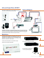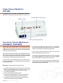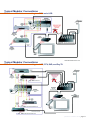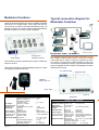
1
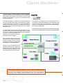
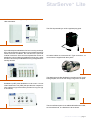
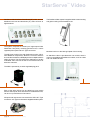
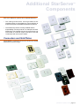
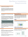
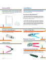
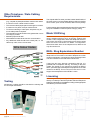
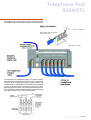
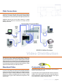
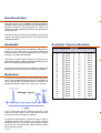
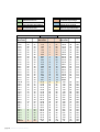
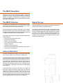
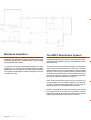
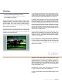
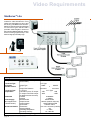
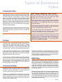
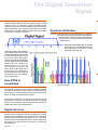
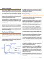
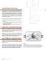
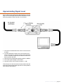
StarServe Installers Guide
Audiovisual distribution for your home.
clipsal.com/cis
[StarServe Installers Guide] page 1
Table of Contents
Preface
4
Structured Cabling System
5
Clipsal StarServe
6
StarServe Lite
7
StarServe Video
10
StarServe Pro
12
Additional StarServe Components
13
StarServe Installation Requirements
19
Labeling & Identification
19
Installation Tools
20
Telephone/Data Cabling Requirements
21
Telephone Hub 8054/6TL
23
Telephone & Data Harmonicas
24
Video Distribution
25
StarServe Video Distribution
27
System Losses
31
Interference and Trouble Shooting
32
Cable
33
Video Requirements
34
System Design
36
Types of Baseband Video
37
The Digital Television Signal
38
[StarServe Installers Guide] page 3
Preface
The StarServeTM Installers Guide has been compiled to
assist installers with the design and installation of the
StarServe system components. This guide is not however,
intended to be a complete guide to all aspects of structured
cabling systems.
Installers of StarServe products should be conversant with
the above documents.
Copyright Notice
©2002 Copyright Clipsal Integrated Systems Pty Ltd. All rights reserved.
The information contained in this guide is advisory only. It is
the responsibility of the installer to be aware of the standards
and regulations that govern the installation practices and requirements for these types of products.
Information presented in this guide is either product specific
or relates to aspects detailed in the following references.
• AS/NZS 3080: Telecommunications Installations Integrated telecommunications cabling systems for
commercial premises
• AS/NZS 3085: Telecommunications Installations Administration of communications cabling systems
• AS 3815: A guide to coaxial cabling in single and multiple
premises
• AS/NZS 3086: Telecommunications Installations Integrated telecommunications cabling systems for small
office/home office premises
• ACA TS 008: Requirement for Authorised Cabling Products
• ACA TS 009: Installation Requirements for Customer
Cabling (Wiring Rules)
• AS 3000: Electrical Installations - Buildings, Structures
and Premises (SAA Wiring Rules)
• ANSI/TIA/EIA-570-A: Residential Telecommunications
Cabling Standard
• ANSI/TIA/EIA-568-A: Commercial Building
Telecommunications Cabling Standard
page 4 [StarServe Installers Guide]
Trademarks
• Clipsal is a registered trademark of Gerard Industries Pty Ltd.
• StarServe is a registered trademark of Clipsal Integrated Systems Pty Ltd.
• Home Management Series is a registered trademark of Clipsal
Integrated Systems Pty Ltd.
• All other logos and trademarks are the property of their respective
owners.
Disclaimer
Clipsal Integrated Systems Pty Ltd reserves the right to change specifications
or designs described in this manual without notice and without obligation.
Structured cabling
systems
Commercial Origins
Structured cabling systems have been installed in commercial
buildings for many years. Their purpose is to distribute
communication services via the cable infrastructure installed
during construction.
Problems with RFI (Radio Frequency Interference), EMI
(Electromagnetic Interference) and other forms of interference
are minimised, as during construction strict cabling standards
can be readily adhered to.
The objective of a structured cabling system is to provide an
infrastructure that supports the ongoing service requirements
of occupants within the building. Whilst an installation may
cater for the initial requirements of the occupants, over time
there will be the requirement to modify, add or change
services within the building. If the building has a structured
cabling system, it will support modifications, additions and
changes with little or no need for recabling.
Residential Implementation
Homes today are implementing a broad number of services
and systems that can rival those of commercial buildings.
Therefore the introduction of structured cabling systems within
the home is becoming a necessity.
In the past, homes typically had one or two telephones on a
single incoming line, video was one antenna connection and
a data network wasn’t a consideration. Now however, homes
may have numerous incoming telephone lines with multiple
handsets, fax machines, answering machines and modems.
Video distribution is no longer a single antenna connection
for receiving free to air television. It may also incorporate
cable TV, Satellite, Video, DVD or CCD cameras. Data
networks are a necessity for those wishing to utilise modern
communication services such as, as PC Networking and
Broadband Internet.
With communication technology advancing at an everincreasing rate, it is logical to cable with future
possibilities in mind. The correct cable infrastructure
will not only maximise the benefit of current systems
and services, but will also provide the flexibility
necessary to implement tomorrows technology.
[StarServe Installers Guide] page 5
Clipsal StarServe
TM
The structured wiring solution offered by Clipsal Integrated
Systems is StarServe. The StarServe system is available in
various basic configurations, all of which incorporate a grid
assembly that allows each system to be expanded to meet
the needs of the user.
The ‘wiring topology’ of a system is its physical layout and
how it is connected. The topology in a structured wiring system
is called ‘Star Wired’ or ‘Home Run’. This is where all the
cables start at a central location (i.e., the StarServe enclosure)
and radiate outward in a star topology to each of the outlets
within the home.
The Star Wired concept means that the cables are only
terminated at the ends, and are never tapped mid-run. There
is only one connection point after the cable exits the StarServe
enclosure, at the wall plate. This
eliminates many problems and also
provides maximum flexibility.
The number of cables being installed should not be
economised. There is little difference in the initial labour costs
between running one or two cables to a single location.
However, should additional cable be required at a later date,
the cost will be significant.
It is important to note that a structured cabling system design
should be independent of the initial equipment being installed.
Each wall plate outlet should have a
minimum of one F-Type connection and
one 8 pin modular connection (RJ45),
cabled with one RG-6 quad shield cable
and Category 5 cable respectively.
However, it is recommended to have
at least two RG-6 and two Category 5
cables at each point, with three RG-6
and three Category 5 cables run to the
main audio/video entertainment area.
“Structured cabling systems are all about infrastructure,
not only for today’s requirements but for tomorrow’s.”
page 6 [StarServe Installers Guide]
TM
StarServe Lite
StarServe Lite is an entry-level system for telephone and
video reticulation.
The VDU is powered by a 12Vdc regulated plug pack.
It provides telephone distribution for four incoming exchange
lines, with each being connected to up to six telephone points
within the home. In addition, the unit has two, 8-pin RJ45
modular connectors. One connector expands the number of
distribution points (utilising an additional wiring hub), whilst
the other connector provides Mode 3 wiring configuration for
security devices.
All coaxial cables are connected via F-Type connectors. 12
connectors are supplied with the system.
The telephone and video distribution modules hook on to the
base grid plate, the cover then simply hangs from the plate.
Broadband (or RF) video distribution is via a one in / six out
Video Distribution Unit (VDU) that provides four outputs for
short cable runs (up to 22 metres) and two for long runs (up
to 45 metres).
There is sufficient space for an additional StarServe module,
such as a data hub, in a StarServe Lite enclosure.
[StarServe Installers Guide] page 7
Mounting StarServeTM
Lite modules
Telephone Connections
page 8 [StarServe Installers Guide]
StarServeTM Lite
Video Connections
StarServeTM Lite
Video & Telephone Connectors
[StarServe Installers Guide] page 9
TM
StarServe Video
StarServe Video distributes Broadband (RF) video, and can
distribute both local and broadcast (TV) video services to
eight locations.
The system comprises of a three input / eight output Video
Distribution Unit (VDU), mounting grid and cover, a 12Vdc
regulated power pack and 12 F-Type connectors.
The VDU has a built in infra-red distribution engine, which,
with additional components, allows the control of devices
such as video recorders or DVD players from multiple locations
within the home. The VDU allows the distribution of locally
modulated video sources as well as commercial free to air
television channels.
The VDU is powered by a 12Vdc regulated plug pack.
Each of the eight outputs can be cabled up to 45 metres
from the VDU. Inputs, such as those from modulated sources,
can be run up to distances of 22 metres.
All inputs and outputs are connected to the VDU via F-Type
connectors. 12 F-Type connectors are supplied with the system.
page 10 [StarServe Installers Guide]
The StarServe Video system is supplied with the same housing
and grid mounting as the StarServe Lite.
Modules hook on to the base grid plate of the housing.
As StarServe video is provided with one module, there is
room for two additional StarServe modules, such as a data
hub or an additional VDU.
Video StarServeTM
Mounting Modules
StarServeTM Video
Video Connections
[StarServe Installers Guide] page 11
TM
StarServe Pro
StarServe Pro has a greater capacity for expansion than the
Lite or Video systems. Telephone, data and video distribution
is combined, with the capacity to add C-Bus DIN rail mounted
devices, such as a C-Bus Network Interface device.
There are two types of
harmonicas supplied with the
StarServe Pro.
• Eight Way Harmonica,
which provides eight
individual RJ45 sockets.
• Eight Way Harmonica,
which provides two banks
of four RJ45 Sockets
(common connections).
The StarServe Pro has provision for two additional harmonicas
of each type.
The StarServe Pro system incorporates the same VDU as
the StarSer ve Video system and has space for an
additional VDU. As the VDU incorporates an infra-red
engine, all the StarServe infra-red accessories can also be
used with the StarServe Pro system.
StarServe Pro is supplied with a cabinet that can be surface
or flush mounted, similar to an electrical distribution board.
The system distributes data and telephone services via 8pin RJ45 modular sockets, in a ‘soft-patch’ configuration, where
the user can change a wall socket’s function by ‘re-patching’.
These soft-patch changes take place at the StarServe Pro
enclosure. To change a telephone outlet to a computer data
outlet, the user would unplug the patch lead from the telephone harmonica and simply plug it into the data hub (optional), assuming the telephone handset has been disconnected from the wall socket.
To enable this flexibility, all telephone and data outlets need
to be terminated in the same way (Refer to the Voice & Data
Section).
Within the StarServe Pro cabinet, a 16 module wide DIN rail
is provided for use with Clipsal C-Bus DIN units such as a
C-Bus PCI (Personal Computer Interface), a CNI (C-Bus
Network Interface) or future C-Bus devices.
Every modular socket on each of the wall plates can be
patched as either a data socket or a telephone socket, or
used for other applications suitable for twisted pair cable.
The additional grid allows up to two, five port switched hubs
to be mounted in the StarServe enclosure.
All outlets are Star Wired back to the StarServe Pro enclosure
and terminated individually on to the 8-pin RJ45 modular
sockets. The sockets are in panels of eight outlets, known
as harmonicas.
page 12 [StarServe Installers Guide]
There are four, 240V power sockets available within the cabinet
for connecting power packs.
TM
Additional StarServe
Components
Each of the StarServe systems can be expanded based on:-
• The cabling infrastructure. If enough cable was not
installed initially, it will probably be cost prohibitive to
expand the system with additional StarServe products.
• The StarServe products currently installed and the
expandability of those products. For example, the Video
Distribution Unit supplied with the Lite system does not
incorporate an infra-red engine and hence infra-red
components will not function if added.
Connectors and Grid Plates
All grid plates or connectors can be sourced from the Clipsal
Electrical Accessories range.
[StarServe Installers Guide] page 13
Infra-red Options
The Video Distribution Unit supplied with both the StarServe
Video and StarServe Pro system is the 8053/8VHPIR. This
VDU incorporates an Infra-red distribution engine. The infra-red
engine comprises of circuitry that facilitates the transmission
of infra-red signals.
Normally, infra-red control works based on line of sight,
therefore the remote control requires an unobscured view of the
equipment to be controlled. However, the infra-red engine in the
StarServe VDU allows audio/video equipment to be controlled
from many locations in the home, as if in the same room.
Infra-red signals received from a hand held infra-red remote
at multiple locations could be routed to a single location where
infra-red transmitting hardware rebroadcasts the signal to a
control device such as a VCR or DVD.
Infra-red Emitters
The electrical connection on the Infra-red Emitter Lead
connects to an emitter output on either a StarServe modulator
or an emitter wall plate. There is a single head IR emitter lead
and a double head IR emitter lead available in the range,
each 1.5 metres in length.
Infra-red Targets
Infra-red targets connect in line on the coaxial cable between
the wall plate and the television. They receive infra-red signals
from remote controls and pass them back to the Video
Distribution Unit along the same coaxial cable that supplies
the video signal.
The targets are powered by the VDU and, if any of the eight
outputs on the VDU senses that no target is present, it will
switch off the power supply to the individual outputs. The
infra-red target incorporates a dc block. Hence, the voltage
will not be passed through to the Television.
The IR emitters are located on or near the equipment to be
controlled (i.e. a VCR).
When a target in a separate room picks up a signal, the
signal is relayed via the infra-red engine in the VDU and
rebroadcast by the emitter.
If the infra-red targets are added at a
later date, or the infra-red system is not
functioning, powering down the VDU for
approximately 30 seconds will reset all
outputs, making the voltage supply
available upon power up.
The emitter diagram above is only an indication of possible
emitter locations and locations should be tested before the
emitter is secured.
page 14 [StarServe Installers Guide]
Infra-red Output Plate, 2031RFT
The Infra-red Output Plate has two emitter sockets, a power
input, and a passthrough F-Type coaxial connecter (one
connection on the front and one on the rear).
Infra-red Diagram
The plate is powered by a 12V regulated plug pack, which also powers the Video
Distribution Unit. Power is applied to the coaxial cable from the rear of an F-Type
connector to power the VDU. Hence, the VDU does not require its own plug pack.
No power passes through to the front F-Type connector.
Modulators
Modulators take a Baseband (Composite) video signal and
audio signal and modulate it onto a Broadband channel. The
channel is user selectable and, once connected to a Video
Distribution Unit, allows that channel to be viewed on any
television connected to a VDU output.
Two channel modulator 8052VMPIR
There are three Modulators in the StarServe range:-
Four channel modulator 8054VMPIR
Single channel modulator 8051VMP
Each Modulator is supplied with
a 12Vdc regulated plug pack.
[StarServe Installers Guide] page 15
Single Channel Modulator
8051VMP
The single channel modulator is configured via a series of
dipswitches, and provides channel selection from UHF 28 - 67.
Baseband video and audio inputs.
Modulator output.
Power Input.
Channel programming dipswitches.
Two & Four Channel Modulators
8052VMPIR / 8054VMPIR
The two and four channel Modulators are internally combined
and provide a single coaxial output. They also provide infra-red
outputs for the connection of emitters. The two channel
modulator provides two emitter connections and the four
channel version provides four.
Each of the modulator video inputs can be assigned a Channel
via the buttons on the front panel. Channel selection is from
28 - 67 in the UHF band. Four different models are available
to suit different international broadcast standards.
The two and four channel Modulators also provide power to
the Video Distribution Unit, this means the VDU does not
require power locally.
Example - To program Input A as channel 42:1. Press the SELECT button until the LED of input A is ON
2. Press the PROGRAM button for the tens value of the
channel to be programmed, in this case four times.
3. The LED will extinguish.
4. Pause until the LED comes back ON.
5. Press the PROGRAM button for the ones value of the
channel to be programmed, in this case two times.
6. The LEDs of the other inputs will give a rapid flash to
indicate the channel has been accepted.
page 16 [StarServe Installers Guide]
To read back a programmed channel, select the channel to
read, press and hold the program button for 5 seconds then
release. The programmed channel will flash back.
If an incorrect channel selection is made, the input LED
flashes repeatedly for about a second.
If a channel is programmed that is plus or minus one or equal
to a channel already in use, the LEDs of the conflicting
channels will flash simultaneously at a slow rate.
If this happens, follow the programming procedure again,
making sure to choose an appropriate channel. It is recommended
the channels used be documented.
Typical Modular Connections
Two Channel Modulator connecting to a DVD and a VCR
Typical Modular Connections
Four Channel Modulator connecting to a VCR, DTV, DVD, and Pay TV
[StarServe Installers Guide] page 17
Modulator Combiner
The StarServe Modulator Combiner is an eight-input, oneoutput device and is designed to combine multiple modulated
sources on to a single output. This output can then be
connected to an input on the Video Distribution Unit. It is
designed primarily to combine single channel Modulators,
and will not pass a dc current or infra-red signals.
Typical connection diagram for
Modulator Combiner
Ethernet Hub 10-BaseT
Single Output
8 Inputs from
modulated sources
The combiner provides a small amount of gain to offset any
losses in the unit.
This unit is powered by a 12Vdc regulated plug pack. It does
not supply any power to the VDU.
The StarServe Ethernet Hub provides connection for up to
five computer network devices. Port 5 on the unit is unused
if the uplink port is used to connect to another hub. Each
por t has a corresponding LED indicating a device is
connected and operating correctly. The power LED indicates
power is available and the collision LED indicates a network
collision has occurred.
Col Collision LED.
Pwr Power LED.
LINK/ACT
Active Links 1-5
Power input.
Catalogue No.
RF Input
Number of Modulator Inputs
Nominal Modulator Input Level
Maximum Number of
Modulated Channels
Connector Type
RF Output
Number of Outputs
Connector Type 1 x F-Type
Output Gain
Modulator Input to Output
Bandwidth
Forward
Reverse
Power Supply
Model Number
(Not supplied with Output Current
E-Series variant) Output Voltage
Input Power
240VAC / 50Hz
Mechanical Details Dimensions
Shipping Weight (approx)
Operating Temperature
Operating Humidity
page 18 [StarServe Installers Guide]
8051/8VCP
Ports 1-5
8
20dBmV
16
8 x F-Type
1
~1dB
400-860MHz
N/A
8050P12/500
500mA (300mA min)
12VDC Regulated
160 x 90 x 60mm
( L x W x D)
1.25kg
0 – 50°C
10 – 95% RH
Uplink port.
Compliance
Network Interface
Uplink Port
Maximum Cable
Length
LED Indicators
Catalogue No.
8055HUB10
IEEE 802.3
Output Ports
1 x RJ45 Port
CAT5 UTP
10Base-T
5 x RJ45 Ports
100 metres (328 feet)
Each Unit
PWR, COL
Each Port
LINK/ACT
Power Supply
Model Number
8050P5/800
(Not supplied with Output Current 800mA (800mA minimum)
E-Series variant)
Output Voltage
5VDC REGULATED (±5%)
Input Power
240VAC / 50Hz
Mechanical Details Dimensions
160 x 100 x 31mm (LxWxD)
Shipping Weight 1kg
Operating Temperature 0 – 50°C
Operating Humidity
10 – 95% RH
StarServe Installation
Requirements
The StarServe system allows distribution of telephone, data
and video services. The installation requirements can be
broken down into these three elements.
Recommendations made in this guide are based on Australian,
New Zealand and US cabling standards. Installation of the
StarServe product should be performed by a licensed or
appropriately certified installer according to the rules,
regulations and standards determined by the relevant
governing bodies.
Labeling & identification
When cabling a StarServe system, it is important that both
ends of each cable are clearly marked. When fitted off,
each termination point on a wall plate should be labeled
for identification.
Labeling wall plates, patch panels and termination devices
(e.g. 110 punch down block) is an essential part of a structured
cabling system. With a number of Category 5 and coaxial
cables running to a single location, it is necessary to be able
to differentiate between cables. This is essential when it
comes to changing the use of cables, e.g., changing from a
telephone point to a data point.
Plate Identification
The Clipsal DataComms Label Printing Software Package is
designed for the Clipsal C2000 Classic Series wall plates
and 30PID labels. This software is distributed free of charge
as par t of the Clipsal Alfred Trade Product Guide on
CD-ROM. It enables installers to quickly and easily print their
own labels. The CD contains an extensive tutorial, which fully
explains how to print labels.
30PID
The Clipsal 30PID is an identification plug that fits in place of a
connector and provides a clear window for viewing a label. The
window allows a label approximately 12mm x 12mm in size.
There are a number of labeling methods which can be
utilised with a StarServe system. Each of the possible labeling
methods vary in suitability for a given installation. Therefore,
the installer should choose a method, which meets the needs
of both the installation and the user.
Colour
Use of colour can help in the identification process, particularly
for the user.
Different colour coaxial cables can be used to differentiate
between upstream (modulated sources) and downstream
(distributed video, including free to air TV) services.
C2000 Labeling System
The Clipsal Classic Series of plates incorporate a window ID
system similar to the plug in 30PID, except the clear
windows sit to the side of each socket and require a
pre-punched cover plate. This window allows a label
approximately 14mm x 6mm in size.
Different coloured 8P8C sockets can also be used to assist
identification on a single wall plate.
Labeling systems should be flexible and should not be
implemented such that a socket is precluded from use as
either a telephone point or a data point.
[StarServe Installers Guide] page 19
Surround IDS
Label Makers
Within the Clipsal 2000 series, there are surround IDs that
allow identification of a plate via a plug in ID number. Whilst it
does not identify single connections, i.e. individual sockets or
F-Type connectors, it can be useful to differentiate between
multiple plates within a single room.
Either used alone or in tandem with the ID systems, label
makers provide a simple and easy way of labeling each point
in the system. The labels are produced on a specialised tape
with a professional result.
Enclosure Identification
The StarServe Lite and Video systems require cable labeling
to be clear and distinct, whilst the StarServe Pro allows
labeling of each 8P8C socket, and therefore less requirement
for labeling on Category 5 cables.
The RG-6 cable in StarServe systems always require labeling,
as they may not necessarily be terminated on dedicated
ports. The labeling of each RG-6 cable within all StarServe
systems is achieved with a dedicated label maker, as these
labels will adhere to the cable. Using a label and clear heat
shrink over the cable is a good alternative.
Installation Tools
Coaxial Cable Stripper
F-Type Crimp Tool
This rotary type stripper allows the cutter depth to be fixed
for the size of cable being stripped.
Ensure that the jaws of the crimp tool cater for the specific
size F-Type crimp to be used.
Modular Crimp Tool
Cable Cutters
A modular crimp tool can be used for making or repairing
patch leads. Clipsal part no.
Rounded blade cutters do not deform the cable.
Clipsal Punch Down Tool
This is required for terminating Category 5 cables on wall
sockets and patch panels. The Clipsal 3100RJA5V is a
universal type punch down tool that is compatible with
different IDC connections.
page 20 [StarServe Installers Guide]
Telephone/Data Cabling
Requirements
Only cabling for services required today will result in an
inflexible system for tomorrow. Cabling for a range of future
possibilities will provide the flexibility to be able to change
the services without the need to recable later.
All telephone and data cabling should be Category 5 or higher,
with Category 5e recommended.
Cable categories refer to the bandwidth available on the
cable, the higher the category the greater the bandwidth.
* Category 1- voice * Category 2- up to 1 MHz * Category 3- up to 16 MHz
* Category 4- up to 20 MHz *Category 5- up to 100 MHz * Category 5e- up to 100 MHz
The category rating of the cable used is dependent on
correct installation practices.
When cabling with Category 5 cable, always adhere to the
appropriate standards and regulations.
Cable Support
Category 5 performance will only be achieved with adequate
cable support.
• Cables (regardless of type) must be supported i.e. they
must not sag or stretch under their own weight.
• Cables should not be pulled across suspended ceiling tiles
or across fluorescent luminaires.
• Cable should not be tied to ceiling grid work wires.
• Where necessary, use approved cable trays, conduit or
Category 5 “J Hooks”.
Cable Pulling
• Avoid tight bends, sharp edges, sharp corners, kinks and
•
•
•
•
•
•
•
turns.
Make pulls as straight as possible.
Do not drag cable around corners.
Gradually pull cable into place.
Pulling tension should not exceed the recommendation of
the manufacturer or 11kgs, which ever is lesser.
Care should be taken to minimise cable twisting.
Avoid unnecessary bends. During installation, keep the
bend radius as large as possible.
The minimum bend radius is ten times the outside
diameter of the cable during installation.
Cable Runs
• Avoid high temperature areas as high temperatures
•
•
•
•
•
•
•
•
•
•
•
increase cable attenuation.
Replace damaged cable.
Apply cable ties loosely.
Avoid sources of EMI.
Run cable at least 150mm away from fluorescent luminaires.
Never exceed 90° bends.
Never over tighten cable ties.
Never step on or run over cable.
Never splice or use bridge taps.
Never use staple guns.
Never overstress the cable.
The maximum horizontal run should be 90 metres from
termination point to wall socket.
Terminations
Category 5 cable runs and terminations on a modular RJ45
socket should be carried out in accordance with the relevant
communications and data standards. Each socket can be
used for either a data or telephone application. If the installation
and termination of data and telephone points are different,
the flexibility of the system will be diminished. All Category 5
terminations should be carried out to T568A Standards.
[StarServe Installers Guide] page 21
Other Telephone / Data Cabling
Requirements
• Cables from a wall outlet to a network interface
•
•
•
•
•
•
•
•
(e.g., computer or printer) should be a maximum of 3 metres.
A minimum of two outlets at each location.
The recommended jumper/patch cord length is 7 metres.
A maximum of 2 patch cords per horizontal run.
To reduce untwisting of cable pairs, strip back only as
much cable jacket as required.
The untwisting of a pair should not be greater than 13mm
for Category 5 cable.
Maintain proper bend radii.
Allow additional cable at each end for re-termination.
Any additional cable should have a fixed path, i.e. if a
cable loop is left, ensure it is secured.
Wire Colour Codes
The Clipsal 5ABLTC tester provides instant identification of
the most common voice and data cabling problems including
short circuits, open circuits, reversals, and incorrect polarity.
Further testing with specialised equipment will be required to
verify the installation meets a specific category rating.
Mode 3/5 Wiring
Mode 3 and Mode 5 are specific wiring configurations for
various telephone devices such as security systems and
modems. This configuration allows the telephone device to
gain priority of the line by disconnecting every device wired
after the mode connection.The Mode 3 configuration
disconnects both wires of the telephone line, Mode 5 will
only disconnect one.
REN - Ring Equivalence Number
The REN relates to a specific device impedance on the
telephone line. The maximum number of telephones or other
customer equipment, connected to a single exchange line at
one time is based on the total REN of all devices.
If there are too many devices connected to the line, it is
possible that no telephone will ring. According to the ACA
TS003. The Carrier is only required to support an REN of
three. (All Austel approved telephone equipment since 1990
identifies its REN).This would mean that the line can
support three telephones with a REN of 1 each.
Licensing
Testing
All Category 5 cables should be checked for continuity and
for correct pair termination.
page 22 [StarServe Installers Guide]
All cabling with the possibility of being connected either
directly or indirectly to the PSTN (Public Switched Telephone
Network) is required to be installed according to the appropriate
standards by a licensed cabler.
Telephone Hub
8054/6TL
The Telephone Hub for the StarServe Lite allows each of the four
incoming lines to be distributed to six points. These lines are
terminated on a punch down block using a 110-termination tool.
110 punch down tool
Keep sheath close to connector
Untwist 13mm max.
Note order of colours
The expansion port (labeled RJ31X) is a special modular
socket that provides line routing for line one, in the same
way as a Mode 3 configuration. With no plug inserted, line
one (Blue Pair) on the left side is connected through the socket
to each of the six line one connections on the right side.
When an eight pin modular connector is inserted in the socket,
this connection is broken locally and needs to be reconnected
via a Mode 3 device such as a security system.
[StarServe Installers Guide] page 23
Telephone & Data
Harmonicas
Incoming Telephone Lines
Incoming telephone lines are terminated on a voice block
located behind the hinged panel and fixed to the rear of the
StarServe Pro enclosure. From the voice block, the telephone
lines are terminated on the telephone harmonicas. The voice
block serves as a disconnect / test point and the telephone
harmonica serves as the distribution device.
The telephone harmonicas have internal
wiring, which link the sockets in two groups
of four. The connections are common across
the four sockets. Each of these banks can
accommodate two pairs (two telephone
lines).This allows the two lines to be
connected to four outlets within a home.
Telephone / Data Outlets
The telephone / data outlets are individually
wired back to sockets on the eight-way
harmonicas.
Each of the eight individual CAT5e sockets are
cabled separate locations within the home
page 24 [StarServe Installers Guide]
Data Connections
The Ethernet Hub attaches to the grid within the StarServe
enclosure. Each port on the Hub can be connected to a network
device (e.g., a network card in a computer) by using the patch
cords to patch to one of the sockets on an eight way harmonica.
Additional devices such as an ADSL modem or a Cable
Modem with an Ethernet connection can also connect
directly to the Hub.
Video Distribution
There are two types of video signal transmission referred to in
the StarServe system, Baseband and Broadband. Baseband
signals are derived from the outputs of DVD Players and VCRs.
These signals are modulated onto a Broadband Signal and
distributed via StarServe using Modulators. Broadband signals
are the signals received from antennas and Modulators. These
signals are distributed by the StarServe VDUs.
Baseband Video
Baseband Video is the transmission of a single video signal
on one or more cables. The signal consumes the entire bandwidth of the cable and does not allow any additional signals.
Typically, this type of video transmission is used over short
distances on coaxial or shielded cable. The number of cables
required for this type of video transmission depends on the
video format.
Composite Video
Composite Video is the only Baseband video that the
StarServe Modulators accept.
Composite Video uses a single cable with an RCA connection,
usually colour coded yellow. The name Composite refers to
the fact that all the components that make the video signal
are combined into a single ‘composite’ signal.
[StarServe Installers Guide] page 25
Broadband Video
Broadband Video refers to multiple video signals transmitted
via a single medium, such as television (terrestrial broadcast),
satellite or cable. Video transmitted over the air (television) is
basically the same as that transmitted over cable or via
satellite. The primary difference between any of the mediums
is the signal level.
To be able to transmit numerous video signals across a single
medium, each video signal must only use a portion of the
available bandwidth.
Bandwidth
Australian Channel Allocation
Bandwidth refers to the amount of information a given device
or cable can reliably transmit. Bandwidth is indicated by a
frequency range. When only a single figure is stated, the
assumed lowest value is zero. The higher the value or broader
the range, the greater the bandwidth.
PAL AUS
Channel No. Freq. (MHz) Channel No. Freq (MHz)
A twisted pair system rated at Category 5 or greater has a
potential bandwidth of 100MHz. RG-6 quad shield cable can
have up to, 29GHz (Gigahertz) bandwidth.
It is important to note that correct installation of cabling and
equipment is critical to maintain the maximum bandwidth.
Modulation
For audio and video signals to be transmitted using only a
portion of the available bandwidth, they are modulated onto
carrier signals within a fixed bandwidth. In Australia, the
standard bandwidth is 7MHz, this is known as a channel.
Analogue signal
If TVs or VCRs are tuned to a particular channel, it is not
tuned into a single frequency, but a 7MHz band from which
the audio and video information is retrieved.
For analogue transmission in Australia the vision carrier is
1.25MHz above the lower frequency for a given channel’s
bandwidth, with the primary audio approximately 5.5MHz
above that. The secondary audio is approximately 242KHz
above the primary audio.
page 26 [StarServe Installers Guide]
28
29
30
31
32
33
34
35
36
37
38
39
40
41
42
43
44
45
46
47
527.25
534.25
541.25
548.25
555.25
562.25
569.25
576.25
583.25
590.25
597.25
604.25
611.25
618.25
625.25
632.25
639.25
646.25
653.25
660.25
48
49
50
51
52
53
54
55
56
57
58
59
60
61
62
63
64
65
66
67
667.25
674.25
681.25
688.25
695.25
702.25
709.25
716.25
723.25
730.25
737.25
744.25
751.25
758.25
765.25
772.25
779.25
786.25
793.25
800.25
StarServe Video
Distribution
The StarServe Video Distribution Units or ‘VDUs’ distribute
broadband video signals to multiple locations within the home
and are designed to simplify MATV design. The 8053/8VHPIR
VDU supplied with the StarServe ‘Video’ and ‘Pro’ allows for
distribution of locally generated video signals in addition to
free to air TV.
StarServe is essentially the distribution end of a MATV system.
Therefore, there is a requirement for a basic understanding of
MATV systems in order to implement StarServe correctly.
The major consideration is the ‘Head-End’ of the system. This
comprises of a combination of antennas, baluns, masthead
amplifiers, filters and couplers. The StarServe VDU’s distribute
the signal provided by the ‘Head-End’ of the system. If this
signal is too weak, noisy or arrived from multiple paths
(‘ghosting’), the signal at each distribution point will be the same.
The Basics of MATV
MATV stands for Master Antenna Television. MATV systems
allow multiple receivers (TV & FM) to receive signals from a
single (Master) antenna, as opposed to individual antennas
for each receiver.
MATV systems are separated into two portions, the ‘Head
End’ and the ‘Distribution System’. When these two portions
are planned and engineered using suitable MATV equipment
and the appropriate installation techniques, signals will be
distributed without loss of signal quality.
Any signal passing through system components, including
the cable, will be attenuated (i.e., have its level diminished).
The level of this attenuation is important, as it will be a factor
in signal quality.
The decibel indicates how many times greater or smaller a
quantity is from a pre-established reference level. The
relationship between dB levels is logarithmic, not linear.
Therefore 40 dB is not twice as much as 20 dB. for example.
• 10 dB = 3.2 x reference level
• 20 dB = 10 x reference level
• 30 db = 32 x reference level
• 40 dB = 100 x reference level
• 50 dB = 316 x reference level
In the MATV industry, the zero reference level is 1,000
microvolts measured across 75 ohms of impedance. The
reference level determines that a minimum signal of 1,000
microvolts is required to produce an acceptable picture.
The dB figure is represented as dBmV (a reference to 1
millivolt), or dBµV (a reference to 1 microvolt).
MATV amplifier gains, cable losses, insertion losses and
isolation values are all expressed in dB. To determine an
amplifier output and any system losses, decibels are added
and subtracted.
The following dB conversion chart highlights minimum to
maximum signal strengths for free to air television signals.
The minimum signal for a good quality, noise free picture is
typically stated as 0dBmV although most televisions will work
with signals as small as -6dBmV. Working to the 0dBmV level
will provide a tolerance to slight signal variations. The signal
level fed into a television should be kept below 20dBmV so
the tuner is not overdriven.
Signal quality within the system is related to signal level,
system noise and headroom. The system needs to maintain
a low noise level and a high signal level. However, the signal
must not be too high, as this can overdrive the equipment.
In order to simplify MATV design, the relationship between
noise and signal levels is measured (in Decibels).
Decibels
The signal level received on a television antenna is measured
in microvolts. Calculations in microvolts are difficult, therefore
MATV calculations are carried out in decibels.
Decibels are added and subtracted, as opposed to being
multiplied and divided. The decibel is 1/10 of a bel and is
derived from a formula originally used by telephone engineers.
[StarServe Installers Guide] page 27
-6 dBmV
Absolute minimum
1 to 6 dBmV
Acceptable signal range
-5 to –1 dBmV
Less desirable than 0dBmV
7 to 19 dBmV
Optimal range of signal
0dBmV
The reference level
20 dBmV
Maximum signal allowable
dB Conversion Chart
Voltage
dBmV
Microvolts
10.00
11.22
12.59
14.13
15.85
17.78
19.95
22.39
25.12
28.18
31.62
35.48
39.81
44.67
50.12
56.23
63.10
70.79
79.43
89.13
100.00
112.2
125.9
141.3
158.5
177.8
199.5
223.9
251.2
281.8
316.2
354.8
398.1
446.7
501.2
562.3
631.0
707.9
794.3
891.3
1000.00
-40
-39
-38
-37
-36
-35
-34
-33
-32
-31
-30
-29
-28
-27
-26
-25
-24
-23
-22
-21
-20
-19
-18
-17
-16
-15
-14
-13
-12
-11
-10
-9
-8
-7
-6
-5
-4
-3
-2
-1
0
page 28 [StarServe Installers Guide]
dBìV
20
21
22
23
24
25
26
27
28
29
30
31
32
33
34
35
36
37
38
39
40
41
42
43
44
45
46
47
48
49
50
51
52
53
54
55
56
57
58
59
60
Voltage dBmV
Microvolts
1.0
1.12
1.26
1.41
1.59
1.78
2.00
2.24
2.51
2.82
3.16
3.55
3.98
4.47
5.01
5.62
6.31
7.08
7.94
8.91
10.00
11.22
12.59
14.13
15.85
17.78
19.95
22.39
25.12
28.18
31.62
35.48
39.81
44.67
50.12
56.23
63.10
70.79
79.43
89.13
100
0
1
2
3
4
5
6
7
8
9
10
11
12
13
14
15
16
17
18
19
20
21
22
23
24
25
26
27
28
29
30
31
32
33
34
35
36
37
38
39
40
dBìV
60
61
62
63
64
65
66
67
68
69
70
71
72
73
74
75
76
77
78
79
80
81
82
83
84
85
86
87
88
89
90
91
92
93
94
95
96
97
98
99
100
Voltage dBmV dBµV
Microvolts
112.2
125.9
141.3
158.5
177.9
199.5
223.9
251.2
281.8
316.2
354.8
398.1
446.7
501.2
562.3
631.0
707.9
794.3
891.3
Volts
1.00
1.12
1.26
1.41
1.59
1.78
2.00
2.24
2.51
2.82
3.16
3.55
3.98
4.47
5.01
5.62
6.31
7.08
7.94
8.91
10
41
42
43
44
45
46
47
48
49
50
51
52
53
54
55
56
57
58
59
101
102
103
104
105
106
107
108
109
110
111
112
113
114
115
116
117
118
119
60
61
62
63
64
65
66
67
68
69
70
71
72
73
74
75
76
77
78
79
80
120
121
122
123
124
125
126
127
128
129
130
131
132
133
134
135
136
137
138
139
140
The MATV Head-End
The Head End of a MATV system usually consists of an
antenna which receives broadcast signals, processing
equipment to filter the signals and a distribution amplifier to
amplify the signals to compensate for distribution losses.
Antennas, amplifiers, taps, filters and attenuates are used in
this portion of the system.
The MATV Antenna
Signal Survey
The quality of TV reception can be no better than the quality
of the signal from the antenna. It is therefore vital to select
the correct antenna for the intended location.
Determining signal levels is one of the most important steps
in Head-End design and a signal survey before installing the
system will avoid many potential problems.
Antenna manufacturers produce geographic maps detailing
preferred antenna types based on the geographic location.
In addition, professional antenna installers carry test equipment
to optimise antenna placement and orientation.
An antenna, several sections of mast, a field strength meter
and a portable colour TV is the equipment required for a signal
survey. The field strength meter measures the amount of signal
received on each channel. Carefully selected antennas can
also do much to overcome certain types of interference. The
portable TV allows the quality of the signal received on each
channel to be determined.
The quality and strength of any signal received is determined
by the following:• Proximity to the transmission tower.
• Power of the transmitter.
• Quality of the transmission.
• Line of sight to the transmission tower.
• Weather conditions.
• Interference from power lines.
• Directional characteristics and orientation of the antenna.
• Level of gain of the antenna.
Antenna Selection
The antenna installation should provide at least 0 dB (1000
µV) of picture signal per channel at the amplifier input.
In strong signal areas this will be relatively easy to obtain. In
weak signal areas a larger antenna with a high gain will usually
be necessary. It may also be necessary to “stack” two or
more antennas. Stacking two antennas will provide an
additional 3 dB of gain above the gain of a single antenna.
Although a pre-amplifier may be used, stacking before
pre-amplification is preferable, as it delivers a cleaner signal
to the system.
Antenna directivity is important. Directivity is a measure of
how well an antenna will reject signals from any direction
other than the front. The front-to-back ratio is one way of
measuring an antenna’s directivity. This is the ratio of the
amount of signal received by the front of the antenna to the
amount of signal received by the rear. A highly directional
antenna will generally have a high front-to-back ratio.
[StarServe Installers Guide] page 29
Masthead Amplifiers
The MATV Distribution System
In weak signal areas, it is often necessary to amplify the
signal before the distribution amplifier. This will ensure a signal
of sufficient strength and acceptable quality. This is achieved
using a Masterhead Amplifier.
A well-designed distribution system is necessary to guarantee
an adequate signal at every receiver connected to the system.
The distribution of MATV is the role of the StarServe Video
Distribution Unit.
It is important to choose a Masterhead Amplifier with a low
noise figure. The noise figure of the Masterhead Amplifier
establishes the noise figure of the entire system, therefore
the amplifier should always increase the signal more than it
increases the noise.
The StarServe VDU simplifies the design and hardware
requirements of the distribution end. VDUs are combiner/
splitter amplifiers in which a single outlet connects to a single
receiver. In this way the system provides a predetermined
signal level and maintains the correct impedance to each of
the outputs. Complex calculation of losses associated with
splitters, drop taps and cable are not required.
Each outlet has a defined amount of gain and there is a
recommendation for the maximum cable run. The VDU will,
in effect, provide the same signal quality to each outlet, as
long as the cable recommendations are adhered to.
If there is a poor signal received from the antenna, this same
poor signal will be output at each of the VDU outlets.To
guarantee a good signal at each of the VDU outlets, as good
quality signal needs to be received at the antenna.
page 30 [StarServe Installers Guide]
Attenuators
As there are many signals received by an antenna, there
may be a wide variation in signs levels. In order to ensure the
same picture quality on all channels, the signal levels may
require equalisation to prevent the stronger signals from
overriding the weaker ones. Equalisation is achieved by
using attenuators, which reduce the incoming stronger signals
by a specified amount.
Attenuators can be either fixed or variable. They are either
designed for one specific attenuation level, or they are
switchable so that the signals can be reduced in increments
to the required level.
Attenuators reduce all signals that pass through by the same
amount. Therefore, frequencies that need reducing need to
be separated from the rest of the signals so that only the
stronger signals are reduced.
Amplifiers
Amplifiers increase the strength of signals received to a level
greater than the losses in the distribution system.The
amplifier gain determines the level of increase, which should
be high enough to provide an acceptable signal level to all
televisions in the system.
Although an amplifiers gain is important, the output capability is
just as important. The amplifier’s specifications should be
checked to ensure that the output level is sufficient to feed the
system and that the strength of the input signal plus the gain of
the amplifier doesn’t exceed the amplifiers rated output capability.
Exceeding the output capability will result in overloading, cross
modulation distortion, and overall signal deterioration.
System Losses
Cable Loss
A certain amount of signal will be lost as it travels through
coaxial cable. This loss depends on the type of cable used
and the frequency of the signal being carried.
Losses are greater at higher frequencies, the greatest loss
occurring at channel 67 in UHF/VHF systems. The cable loss
should always be calculated at the highest frequency received
or the highest frequency to be received in the future.
Splitter Loss
When a two-way splitter is inserted in-line, the signal in each
leg will be approximately 3.5 dB less than that of the main
line. If a 4-way splitter is inserted in-line, the signal in each
leg is 6.5 dB less than that in the main line. The signal sent
to each branch of the system will be equal to the signal sent
into the splitter minus the splitter loss. That is, an input of 30
dB into a 2-way splitter will deliver a signal of 30 dB minus
3.5 dB splitter losses, or 26.5 dB to each branch of the System.
For initial calculation, the tapoff values and the insertion losses
are estimated as the output of the amplifier will influence the
final selection tapoff values.
Isolation Loss
Each tapoff attenuates the signal by a specified number of
dB to prevent one set from interfering with another. For
example, if there is a 25dB signal in the line, and a 23dB
isolation wall tapoff is inserted in the line, the signal available
at the tapoff would be 2dB. The 23dB loss is called Isolation
Loss. In computing the total distribution system losses,
calculate the isolation loss of the last tapoff only. Since the
system design requires a minimum of 0dB (1000 µV) to each
set, the lowest isolation value should be used. For most MATV
tapoffs this value is 12dB.
Insertion Loss
All tapoff devices inserted into the distribution system create
signal loss. This type of loss is called insertion loss, (sometimes called feed-through loss). On the line, the insertion
loss of each tapoff is subtracted from the signal carried by
that line. When estimating total system losses, the insertion
loss of each unit is added together to find the total insertion
loss for that system. For example, if there are 10 tapoffs on
the line, and each tapoff has an insertion loss of 0.5 dB, the
total insertion loss is 5 dB.
[StarServe Installers Guide] page 31
Interference and
Trouble Shooting
Cross Modulation Interference
Cross modulation interference occurs in Broadband
preamplifiers and distribution amplifiers when one or more
signals (TV Channels) exceed the amplifiers rated output
capability. This causes two or more signals (TV channels) to
beat together resulting in the picture information of one channel
appearing superimposed upon another. This interference
usually manifests itself as a windshield wiper effect or as a
negative image.
The windshield wiper effect is seen as the vertical or
horizontal framing bars of the interfering channel appearing
on the channel being viewed. The negative image appears as
a superimposed image in the background of the picture on
the channel being viewed.
Co-Channel Interference
Co-channel interference is the result of two stations in different
locations operating on the same channel. It appears on a TV
as two different pictures, as though one were placed on top
of the other. The effect can be minimised by using a highly
directional antenna, or, if necessary, by stacking antennas.
Highly directional antennas and the use of filters and taps to
attenuate and control the offending signals can usually
eliminate this type of interference.
It is always the strongest signal received that causes the
interference and it does not normally show up on the interfering
channel. The interfering signal may also be an FM signal or
combination of FM and TV signals.
Power Line Interference
Power line interference is caused by radiation from a high
voltage power line close to the antenna. To minimise this
interference, the antenna should be located as far away from
the power line as possible. A balun should be used as close
as possible to the antenna terminals to prevent direct pickup
of radiation.
Adjacent Channel Interference
Adjacent channel interference is caused by a strong signal
from one channel overriding a weaker signal on an adjacent
channel, producing a “herringbone” effect. An adjacent channel
is one, which is next to another channel. For example,
Channels 1 and 2, 7 and 8, 10 and 11 are adjacent channels.
Channels 2 and 3 are not adjacent because there is a 15
MHz band between them. In addition, channels 5 and 6 are
not adjacent because there is channel 5A between them.
This interference can be eliminated by using a higher gain
antenna to increase the weaker signals and by using
attenuators to reduce the stronger signals.
page 32 [StarServe Installers Guide]
Worn or cracked insulators on power lines can also cause
this interference. If the interference shows up intermittently
(especially during wet weather), it may be due to cracked
insulators on the power lines.
Ghosting
There are three common causes of ghosting:• Pickup of reflected signals by the antenna.
• Direct pickup of a signal by the TV or TV lead.
• Poor installation techniques.
Not all signals reach an antenna directly. They can be
reflected by buildings, mountains, or bodies of water. These
reflected signals arrive at the antenna microseconds after
the direct signal. This causes a second, fainter image to
appear on the TV screen, just to the right of the main image.
This is called a trailing ghost.
A trailing ghost can usually be eliminated by using a highly
directional antenna or by stacking antennas. Changing the
orientation of the antenna slightly may also eliminate the
reception of the reflected signal.
A second image appearing to the left of the main image is
called a leading ghost. This is the result of the direct pickup
of signal by the TV lead (when using 300-Ohm twin lead), by
the TV tuner itself or by the down lead from the antenna.
A leading ghost sometimes occurs in strong signal areas
when signal is picked up directly and displayed microseconds
before the image picked up by the antenna. Since 300-Ohm
twin lead is unshielded and can act like an antenna, it should
be removed and replaced with 75-Ohm coaxial cable. A balun
should be placed as close as possible to the antenna terminals
and the coaxial cable connected to the TV set with a matching
transformer. Overpowering the unwanted signal can also
eliminate this type of ghosting.
Poor installation techniques can cause ghosting. If the
distribution line installations are improperly terminated, the
signal can bounce up and down the line, causing multiple
images. Proper use of terminators can eliminate this problem
at the time of installation.
Poor crimping of “F” fittings can cause an impedance
mismatch, and can result in reflected signals in the line. Using
a good crimping tool and making sure that all fittings and
splices are correctly executed will help ensure trouble free
operation of a system.
Cable
StarServe video cabling should be cabled with RG-6, quad
shield, 75-Ohm coaxial cable. Coaxial cable is a concentric
transmission line. It consists of a central conductor, a
dielectric medium (such as polyethylene) which fixes the
spacing between the central conductor and an outer shield
(such as copper braid or aluminum foil) and a weatherproof
outer jacket (usually vinyl).
All StarServe coaxial cable connections use standard
F-Type connectors for faster, easier installation.
Losses in coaxial cable are specified as attenuation per metre
of cable.
[StarServe Installers Guide] page 33
Video Requirements
StarServeTM Lite
The StarServe Lite VDU provides six
outlets for video distribution. Four
outlets are designated as short and
two as long. The distance recommendation for both short and long is based
on the level of gain that the VDU
provides. Cable lengths in excess of
the recommendations will work, as long
as the incoming signal level (i.e. the
antenna signal) is suitably high.
Catalogue No.
8051/6VHP
RF Input
Max CATV/Antenna Input
(64 channels)
Connector Type
RF Output
Number of Runs
1 x F-Type
Output Type
LONG
SHORT
2
4
Output Run Distance
45 metres
22 metres
2 x F-Type
4 x F-Type
CATV/Ant input to TV output
4dB
1dB
TV output to CATV/Ant input
-8dB
-12dB
(5-42 MHz reverse channel)
Forward
54-860MHz
Reverse
5-42MHz
Model Number
8050P12/500
Output Current
500mA (300mA minimum)
Output Voltage
12VDC REGULATED
Input Power
240VAC / 50Hz
Dimensions
175 x 88 x 23.3mm (LxWxD)
Shipping Weight
1kg
Operating Temperature
0 – 50°C
Operating Humidity
10 – 95% RH
Specifications typical @ 25ºC ± 5ºC
Connector Type
Output Gain
Bandwidth
Power Supply
(Not supplied with
E-Series variant)
Mechanical Details
page 34 [StarServe Installers Guide]
20dBmV
StarServeTM Video & Pro
The Video Distribution Units (80053/8VHPIR) in StarServe
Video and Pro can be coupled together to expand the number
of outputs.
Catalogue No.
8053/8VHPIR
RF Output
Number of Runs
8
Output Run Distance
45 metres
Connector Type
8 x F-Type
Output Gain
CATV/Ant input to TV output
3dB
Modulator input to TV output
-10dB
Bandwidth
Forward
54-860MHz
Reverse
N/A
Isolation
Modulator input to CATV/Ant
>80dB
RF Input
Max CATV/Antenna Input
20dBmV
(64 channels)
Connector Type
1 x F-Type
Power Supply
Model Number
8050P12/500
(Not supplied with Output Current
500mA (300mA minimum)
E-Series variant)
Output Voltage
12VDC REGULATED
Input Power
240VAC / 50Hz
Mechanical Details Dimensions
160 x 90 x 60mm (LxWxD)
Shipping Weight (approx)
1.25kg
Operating Temperature
0 – 50°C
Operating Humidity
10 – 95% RH
Specifications typical @ 25ºC ± 5ºC
[StarServe Installers Guide] page 35
System Design
Points To Remember
• All video distribution should use RG-6 Quad Shield cable,
•
•
•
•
even the short leads from the wall plate to the TVs.
The total length for any RG-6 cable run should not exceed
the recommended lengths.
All telephone and data should be cabled with Category 5
cable or greater. This higher grade cable isn’t required for
telephone service, however having both data and telephone
points cabled with Category 5 gives the flexibility to
interchange those services.
No Category 5 cable runs should exceed 90 metres.
The StarServe enclosure should be located such that
cable runs are minimised.
Determine the number of points
required (telephone / data / video)
The number of cables and outlets to be installed is a subjective
requirement of a StarServe system. It is primarily up to the
user to determine the level of infrastructure required for the
installation, with recommendations from the installer.
It is essential that the user is made aware of the varying
level of infrastructure that can be implemented. A balance
needs to be made between cost and flexibility. This can only
be done by a user who understands the long term benefits of
a structured wiring system.
Various standards make recommendations for minimum
cable infrastructure, from these the following guidelines are
suggested.
Grade Infrastructure 1 - 2 x Category 5 cables
1 x RG-6 Quad Shield cable
Grade Infrastructure 2 - 2 x Category 5 cables
2 x RG-6 Quad Shield cable
Grade Infrastructure 3 - 3 x Category 5 cables
2 x RG-6 Quad Shield cable
Plan The Installation
Before any cabling is done it is important to plan the entire
installation. Firstly, all required services need to be assessed:• How many incoming telephone lines.
• How many telephone points / Telephones.
• How many lines to each point.
• How many data points.
• How many television points.
• How many Modulators.
page 36 [StarServe Installers Guide]
Once these requirements are established, future possibilities
can be determined. It is important to make future allowances
when determining the number distribution points required. This
will greatly determine the flexibility of the system and its
future benefits.
Emphasis On Future
Requirements
In residential buildings, the purpose in having a structured
cabling system is to allow for both current and future service
requirements.
Only cabling for the services required today will leave an
inflexible system for tomorrow. An installation should be
cabled for a range of future possibilities. This provides the
flexibility to be able to change the systems within a home,
without the need to recable.
Types of Baseband
Video
Composite Video
Composite Video is the most familiar format. It uses a single
cable with RCA or Phono connections, usually colour coded.
Composite refers to the fact that all components that make
the video signal are combined into a single ‘composite’
signal. This means that the ‘Luminance’ (Black & White
detail), ‘Hue’ (Red, Green & Blue colour balance), ‘Saturation’
(the richness of the colour) and sync pulses are all combined.
The way in which these components are combined is
determined by the colour-encoding format (e.g., NTSC,
SECAM and PAL). PAL is the encoding video format used in
Australia and New Zealand.
Composite video components can interact with one another,
distorting the signal. In particular, this can occur when
passing through cable, equipment or being recorded and
played back.
S-Video
PAL (Phase Alteration Line) Format
The basic principle of colour video is red, green and blue
signals are encoded with a colour sub carrier, then added
together to form the composite video signal.
Video signal strength is measured in percentages of the peak
signal voltage. As the voltage approaches 100%, the picture
gets brighter. As the voltage approaches 0%, the picture
approaches black.
To determine colour hue and saturation, video monitors and
other decoding equipment compare the colour sub carrier’s
phase and amplitude with a reference signal.
The amplitude of the sine wave describes how deeply an
object is saturated with colour. When the amplitude is
increased, the displayed colour becomes deeper.
The phase of the sine wave describes the hue of the object
and the dc offset voltage of the sine wave determines how
bright an object is. As the offset voltage is decreased, the
displayed object becomes darker. This is most noticeable
when there is impedance mismatch, i.e. when a single video
source is connected to two inputs.
To avoid the picture degradation that can occur with
composite video, manufacturers provide a different type of
video output and input format called S-Video. In S-Video
format, the chrominance (all colour information) is kept
separate from the luminance (Black & White information) and
sync information. This reduces the possibility of interaction.
S-Video signals are transferred via twin coaxial or shielded
cables, which are usually fitted with a 4-pin mini DIN plug.
Most equipment fitted with S-Video connectors also provides
standard composite video connectors.
S-Video can be recorded on videotape (S-VHS), where the
two chrominance and luminance remain separated.In
principal, the longer these two components remain separated
within a system, the less degradation of the signal. It is
generally better to use an S-Video connection as opposed to
the lower quality composite video.
Component Video
Component Video provides the best picture quality of all
analogue formats. In component video, the components of
the video signal are separated to a greater extent than
S-Video, with less chance of them interfering.
Instead of just separating the luminance/sync (Y) and the
chrominance (C) information, the chrominance information is
further separated into its own two components, the B-Y (blue
minus luminance, also called Cb or Pb) and R-Y (red minus
luminance, also called Cr or Pr).
Although not available on all video equipment, this type of
connection is becoming more popular as it produces the best
picture quality. The connections found are three RCA/Phono
sockets, generally marked Y/R-Y/B-Y or Y/Cr/Cb and oftencoloured yellow, red and blue respectively.
RGB Video
RGB is similar to component video and consists of the three
basic colour components, red, green and blue. Sometimes
the sync information is combined with the green video, and
sometimes separated. It is used primarily in European
equipment, where video connections between equipment are
made using multi-way SCART connectors (20 pin oblong
connectors). Like Component video, RGB offers the potential
of high image quality.
RGB and Component Video are not interchangeable and one
type cannot be fed directly into the other. Equipment fitted
with a SCART connector does not necessarily mean it is
capable of handling RGB video. SCART connectors are used
to convey all three types of video, Composite, S-Video and
RGB. Always refer to the manufacturers manual to determine
the video formats supported.
[StarServe Installers Guide] page 37
The Digital Television
Signal
The ‘digital’ signal used for Digital Terrestrial Television Broadcasting (DTTB) is different to the PAL analogue signal. DTTB
utilises a form of modulation called COFDM (Coded
Orthogonal Frequency Division Multiplex) and is defined by
DVB-T standards. The purpose of COFDM is to provide a
vehicle for the carriage of digital signals that is highly robust
to the effects of echoes or ghosts.
COFDM spreads data between
many carriers. Either of two modes
of COFDM may be employed, with
the ‘2k mod’ having 1705 carriers
and the ‘8k mode’ having 6817
carriers. The power is spread evenly
over a 6.7MHz portion of the 7MHz
channel. This is in contrast to an
analogue service, with its
concentration of power in the
vision carrier at the lower end of
the spectrum. The difference in
power distribution has important
consequences for the measurement of signal level.
How DTTB is
transmitted
Digital Terrestrial Television Broadcasting is transmitted
using digital modulation in the channels available in Bands
III, IV and V, sharing the spectrum with the current analogue
transmissions. Unlike analogue transmissions, there is no
Band I or Band II transmissions for DTTB.
Existing TV transmitters will generally be used for DTTB
transmissions. Although successful reception via existing
antennas will normally be experienced, optimum reception of
DTTB may require some modifications.
Digital Services
Each Digital Service will occupy a 7 MHz channel and may
contain a HDTV programme, a SDTV programme or multiple
programmes, all available in 16:9 display format. Associated
with the picture will be surround sound up to ‘5.1’ channels,
together with text and data information, closed captions for
the hearing impaired and the potential for interactive
enhancements.
page 38 [StarServe Installers Guide]
Spectrum Utilisation
For those VHF allocations in state capital cities, a spectrum
arrangement has been adopted where the adjacent
channels will be used to transmit DTTB at a lower
power than the existing VHF analogue PAL
transmissions.
The actual ratios between PAL and DTTB
will depend upon the detailed planning
and interference restrictions in and
around the particular city.
Same Coverage
A planning requirement for all service areas is the concept of
‘same coverage’, where the introduced DTTB service is
received by viewers currently receiving an analogue service.
For reliable long-term reception of a digital service, the level
and quality of the signal needs to have sufficient margin to
stay away from the cliff edge!
It is important to ensure the signal level variation is adequate
for the long-term robustness of the DTTB reception, rather
than installing a ‘just adequate’ antenna system. This
requirement for successful long-term DTTB reception may
usually be met by ensuring the receiving antenna provides
successful and robust analogue reception.
Digital TV Signal Levels
The greater efficiency of digital modulation results in less
power required to provide the ‘same coverage’. Depending on
the planning requirements of the particular area’s digital
coverage, the power for digital may be as low as one-tenth of
the analogue power.
The digital services will normally be transmitted via the same
antennas as the current analogue services. Hence the ratios
of digital to analogue powers will be similar in all directions.
The received signal level required in a particular location to
achieve long-term successful reception of all digital services
will depend on the following.
The measurement of the signal level delivered to the input of
the receiver is the initial easy check on the suitability of the
installation. The levels recommended below have allowances
to cater for reception of Band III, IV and V in most environments
experienced in city and rural locations.
The rule of thumb developed in analogue reception is 1mV or
60dB µV for a successful installation. The potential rule of thumb
for digital TV reception is 0.5mV or 54dB µV. This guide for
digital signal levels is correct if the analogue service in the
presence of the digital service is of fair quality, i.e., if the
analogue service has moderate ghosting and little interference.
Other important information on Digital TV Signal Levels:a) When the antenna system has an amplifier, the maximum
limit is still applicable to the receiver input, but the minimum
and preferred levels are now applicable to the amplifier’s input.
In amplified systems, the Carrier to Noise ratio should be
measured and should be a minimum of 29dB (preferably 43dB).
The Digital Cliff Edge
Unlike an analogue TV signal, which can be viewed at weak
signal strengths or in corrupted conditions, DTTB TV picture
and sound will either be perfect, in the process of breaking
up or non-existent.
The penalty for near perfect pictures and sound is that DTTB
reception exhibits a very rapid change from being excellent
to disappearing. This phenomenon in general is referred to as
the ‘digital cliff edge’ or ‘threshold’.
b) The lowest level that can be received and still provide
picture and sound (the threshold or cliff edge), is approximately
31dBµV, when there is little multipath and no interference.
c) The nominal modulation parameters are 64QAM with a
2/3 FEC. Other alternate modulations, for example of 64QAM
with a 3/4 FEC, will have a different minimum reception level
of approximately 33dBµV.
The cliff edge characteristic invites the definition of a margin
the signal has to achieve before the cliff edge is reached. By
the insertion of an attenuator in the input of the receiver or
amplifier, the level margin may be found.
Digital
Analogue
d) The recommended minimum level margin is 9dB for the
first level of caution. This will cater for short and long-term
variations. Obtaining the preferred level, in ideal reception
conditions, would produce a preferred level margin of greater
than 20dB. With more complex multi-path reception conditions
and modulation using 3/4 FEC, this level margin may be
reduced to perhaps 16dB.
All the channels expected to be received must be received
reliably. Hence the level margin must be checked on all
channels. Further quality checking must also be assessed
on all channels.
[StarServe Installers Guide] page 39
Impulse Noise Interference
Impulse noise from house appliances, vehicle ignitions or
overhead power lines may interfere with the reception of the
digital services, causing intermittent picture blocking or
freezing. The disturbance to sound may be of greater
annoyance. Both level and quality margins may be consumed
by the interference caused by impulse noise. If the interference
is not being received via the antenna, an increased signal
level (either by use of an amplifier or a higher gain antenna)
may reduce the problem.
Further improvement to reception quality may be provided by:a) Correct matching of the antenna cable to the antenna
balun.
b) Use of double or quad screened cables between the
antenna and outlet plate.
c) Use of double or quad screened fly-lead from the wall
outlet to the receiver.
Interference From Other Services
Interference from adjacent channels or co-channel broadcast
services may result in reduced margins. As experienced in
analogue reception, a reduction in the level of the interference
is the first approach to a solution.
Depending on the direction from which the interference is
originating, antenna repositioning or antenna type may provide
a solution. The performance of the receiver to these types of
interference varies between models and brands.
How To Measure Signal Strength
Professional installers have access to field strength meters.
However, for a rough guide on signal strength, a variable
attenuator can be used. These are available from most
electronic stores.
Attenuators are approximately linear devices and, by noting
the position of the dial, the attenuation can be estimated
within a few dB. Marking the attenuator will assist in
approximation. For example, if the attenuator is variable from
0dB to 20 dB then midway will be approximately 10dB.
page 40 [StarServe Installers Guide]
Note:A. The attenuators do not come with 0-20dB markings.
B. The numbers refer to the amount that the signal is reduced.
C. Do not leave these units in a system permanently.
Approximating Signal Level
The tuner in modern televisions have a ‘knee’ in performance at
about -10dBmV input signal strength. Below this ‘knee’, the noise
begins to increase rapidly. (Note: Noise is identifiable as snow.
If there is a pattern to when it is seen, it is not noise).
1. Connect the variable attenuator to the TV set and tune to
a station.
2. Increase attenuation until the ‘knee’ is found (the point
where noise begins to rapidly increase). Noise is easiest
to see on a black background, wait until the screen turns
dark to perform this test.
3. Note the amount of attenuation add this number to -10dBmV.
4. This is the signal strength of this station.
5. Typical accuracy of this method is about +/- 3dB.
This technique can also be used to identify stations that are
far stronger than the other stations (these can cause problems
when using an RF amplifier).
[StarServe Installers Guide] page 41
Notes
page 42 [StarServe Installers Guide]
Products of
Clipsal Integrated Systems Pty Ltd
ABN 15 089 444 931
Head Office
12 Park Terrace, Bowden
South Australia 5007
PO Box 103 Hindmarsh
South Australia 5007
Telephone
(08) 8269 0560
International +61 8 8269 0560
Facsimile
International
(08) 8346 0845
+61 8 8346 0845
Internet
E-Mail
www.clipsal.com/cis
cis@clipsal.com.au
Offices in all States
NSW Sydney
Albury
(02) 9794 9200
(02) 6041 2377
VIC
Melbourne
Country Areas
(03) 9207 3200
1800 653 893
QLD
Brisbane
Townsville
(07) 3244 7444
(07) 4729 3333
SA
Adelaide
(08) 8268 0400
WA
Perth
(08) 9442 4444
TAS
Hobart
Launceston
(03) 6272 3177
(03) 6343 5900
NT
Darwin
(08) 8947 0278
International Enquiries
Head Office Export Department
Telephone
+61 8 8269 0587
Facsimile
+61 8 8340 7350
E-Mail
export@clipsal.com.au
New Zealand
Clipsal Industries (NZ) Ltd (Auckland)
Telephone
+64 9 576 3403
Facsimile
+64 9 576 1015
E-Mail
headoffice@clipsal.co.nz
Customer Service
Free Facsimile (0508) 250 305
Auckland/
Mobile Phone (09) 572 0014
Free Phone
(0508) CLIPSAL
2547725
Malaysia
Clipsal Integrated Systems (M) Sdn Bhd
Level 3, Unit 3-2, C P Tower
Jalan Damansara
46350 Petaling Jaya
Telephone
+60 3 7665 3555
Facsimile
+60 3 7665 3155
E-Mail
clipsal@clipsaltech.com.my
Singapore
CIS Pte Ltd (Singapore)
No. 8, Jurong Town Hall Road
#24-05-06 The JTC Summit
Singapore 609434
Telephone
+65 266 1998
Facsimile
+65 266 3922
E-Mail
clipsal@clipsaltech.com.sg
page 44 [StarServe Installers Guide]
International Representatives
China
Clipsal China Ltd
Telephone +86 755 246 1122
Greece
Clipsal Hellas S.A.
Telephone +30 1 0993 9165
You can find this brochure and many
others online in PDF format at:
clipsal.com
Follow the links off the home page or
access the following page directly:
clipsal.com/wat_lib_pdf.cfm
clipsal.com/cis
Hong Kong
Clipsal Integrated Systems (HK) Limited
Telephone +852 2 487 0261
South Africa
Clipsal South Africa (Pty) Ltd
Telephone +27 11 314 5200
Taiwan
Clipsal (Taiwan) Co Ltd
Telephone +886 2 2558 3456
Thailand
Clipsal Thailand Ltd
Telephone +66 2 952 5338
United Kingdom
Clipsal Ltd (UK)
Telephone +44 1494 521 111
Clipsal Integrated Systems Pty Ltd reserves the right
to change specifications, modify designs and
discontinue items without incurring obligation and
whilst every effort is made to ensure that descriptions,
specifications and other information in this catalogue
are correct, no warranty is given in respect thereof
and the company shall not be liable for any error
therein.
©
Copyright Clipsal Integrated Systems Pty Ltd
Printed by Custom Press Pty Ltd (08) 8346 7999
O/N 892-957 March 02/02