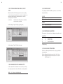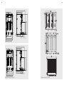
1
1 THYRO-A THYRISTOR-LEISTUNGSSTELLER / THYRISTOR POWER CONTROLLER MARCH 2015 8000029381 DE/EN - V11 2 1 THYRO-A THYRISTOR-LEISTUNGSSTELLER / THYRISTOR POWER CONTROLLER MARCH 2015 8000029381 DE/EN - V11 2 3 CONTENTS 1.General 1.1 Type designations/Validity 1.2 Abbreviations 1.3 Special Features 1.4 Warranty 7 7 10 10 11 2. Safety 2.1 Identification in the operating instructions 2.2 General danger information 2.3 Operator requirements 2.4 Personnel requirements 2.5 Intended use 2.6 Use of the device 2.6.1 Operation 2.6.2 Prior to installation/commissioning 2.6.3 Maintenance, service, faults 2.6.4 Transport 12 12 13 13 14 14 15 15 15 16 17 3. Functions 3.1 Operating modes 3.1.1 Full wave switch principle TAKT 3.1.2 Phase angle principle VAR 3.1.3 Half wave switch principle QTM 3.2 Setpoint processing 3.3 Control modes 3.4 Limits 3.5 Pulse inhibition 3.6 Current and voltage transformer (only for ...H RL1 and ...H RLP1) 3.7 Display via analog output (only for ...H RL1 and ...H RLP1) 3.8 Error and status messages 3.8.1 LED messages 3.8.2 Fault signalling relay K1 (only for ...H RL1 and ...H RLP1) 3.9 Monitoring 3.9.1 Monitoring the mains voltage 3.9.2 Load monitoring (only for ...H RL1 and ...H RLP1) 3.9.3 Device temperature monitoring 3.9.4 Fan monitoring (for ...F...) 3.10 Extended functions (with bus module/Thyro-Tool Family) 3.10.1 Extended operating modes/circuit types 18 18 18 19 19 19 20 23 23 23 24 24 29 31 32 32 33 33 33 33 34 3.10.2 Averaging for the analog output 3.10.3 Control limits 3.10.4 Controller parameters 3.10.5 Mains load optimization 34 35 35 35 4. Settings and operation 4.1 Device overview 4.2 DIP switches S1 4.2.1 Operating mode and load types 4.2.2 Control mode/Analog output 4.2.3 Set point input range 4.2.4 Analog output (only for ...H RL1 and ...H RLP1) 4.3 Potentiometer 4.3.1 Setting the transformer load (AN1, SST, T0) 4.3.2 Setting ohmic load 4.3.3 Setting maximum load value with control end U, U2 and P control 4.3.4 S etting maximum load current (only for ...H RL1 and ...H RLP1) 4.3.5 S etting example for maximum load value at control end / maximum load current 4.3.6 Adapting analog output (scale) (only for ...H RL1 and ...H RLP1) 4.3.7 Setting load monitoring (undercurrent monitoring) (only for ...H RL1 and ...H RLP1) 36 37 39 41 41 42 42 43 44 45 46 48 51 5. Installation 5.1 Connecting terminals (Overview) 5.2 Connecting power supply 5.3 Connecting additional electronics supply (only for ...H RL1 and ...H RLP1) 5.4 Connecting pulse inhibition 5.5 Connecting analog setpoint input 5.6 Connecting control input for switch operation 5.7 Connecting the bus module 5.8 Using the analog output (only for ...H RL1 and ...H RLP1) 5.9 Using the Thyro-Tool Family 59 61 63 63 64 64 64 65 66 66 6. Mains load optimization 6.1 Internal mains load optimization 6.2 Synchronization with Thyro-Power Manager 6.3 Software synchronization (operating mode TAKT) 69 69 69 70 49 50 7. Connecting diagrams 72 8. Help in the event of problems 80 9. Technical data 83 4 10. Dimension drawings 5 90 11. Accessories and options 105 12. Approvals and conformity 106 LIST OF FIGURES AND TABLES Fig. 1 Fig. 2 Fig. 3 Fig. 4 Fig. 5 Fig. 6 Fig. 7 Fig. 8 Fig. 9 Fig. 10 Fig. 11 Fig. 12 Fig. 13 Setpoint inputs and effective setpoint Operating elements User surface THYRO-TOOL FAMILY Connection diagram Thyro-A 1A...H1 Connection diagram Thyro-A 2A...H1 Connection diagram Thyro-A 1A ...H RL1, ... H RLP1 Connection diagram Thyro-A 2A ...H RL1, ... H RLP1 Connection diagram Thyro-A 3A...H1 Connection diagram Thyro-A 3A ...H RL1, ... H RLP1 Load connection types Additional electronics supply and connection with optional bus module Connection diagram mains load optimization with Thyro-Power Manager Connection diagram mains load optimization for operating mode TAKT 19 62 68 72 73 74 75 76 77 78 78 79 79 Tab. 1 Tab. 2 Tab. 3 Tab. 4 Tab. 5 Tab. 6a Tab. 6b Tab. 7a Tab. 7b Tab. 7c Tab. 8 Tab. 9 Tab. 10 Tab. 11 Effects of a change in the load resistance Effective limits Limit values for mains voltage monitoring Maximum load value at control end Maximum load current Analog output (scale) Thyro-A 1A, 2A Analog output (scale) Thyro-A 3A Load monitoring A 1A/2A, star delta, without neutral Load monitoring Load with common star point and without neutral conductor Load monitoring , A 2A, star point Load with common star point and without neutral conductor Load in delta connection Other possibilities of load monitoring Connecting terminals (Overview) 22 23 32 47 48 50 50 53 54 55 56 57 58 61 6 7 CONTACT 1. GENERAL TECHNICAL QUERIES Do you have any technical queries regarding the subjects dealt with in these operating instructions? If so, please get in touch with our team for power controllers: Tel. +49(0)2902 763-520 or 763-290 Fax +49(0)2902 763-1201 COMMERCIAL QUERIES Do you have any commercial queries on power controllers? If so, please get in touch with our team for power controllers. Tel. +49 (0)2902 763-558 or (02902) 763-591 powercontroller@aei.com SERVICE Our team is at your service on the following hotline: Advanced Energy Industries GmbH Emil-Siepmann-Straße 32 D-59581 Warstein Tel. +49 (0)2902 763-558 www.advanced-energy.com COPYRIGHT No part of these operating instructions may be transmitted, reproduced and/or copied by any electronic or mechanical means without the express prior written permission of Advanced Energy. © Copyright Advanced Energy Industries GmbH 2014. All rights reserved. FURTHER INFORMATION ON COPYRIGHT Thyro-A is an registered trademark of Advanced Energy Industies GmbH. Windows and Windows NT are registered trademarks of the Microsoft Corporation. All other company and product names are (registered) trademarks of the respective owners. The Thyro-A is a communication-capable thyristor power controller. It can be used wherever alternating voltages, alternating currents or outputs in thermal process technology need to be controlled. The Thyro-A has several different control and regulation modes, can easily be connected to process and automation technology, has a high degree of control accuracy and is simple to handle. These operating instructions describe the configuration and functions of the Thyro-A and are designed to enable qualified personnel to perform the following work: • planning • commissioning • maintenance and repair 1.1 TYPE DESIGNATIONS/VALIDITY These operating instructions describe the Thyro-A series versions ...H 1, H RL1 and ...H RLP1. Product characteristics that are only provided by the Thyro-A ...H RL1 and ...H RLP1 series are marked in the text. These operating instructions comply with the current technical specifications of the device at the time of publication. The contents do not constitute a subject matter of the contract, but serve for information purposes only. We reserve the right to alter any specifications given in these operating instructions, especially with regard to technical data, operation, weights and dimensions. Advanced Energy reserves the right to make modifications with regard to the content and technical data in these operating instructions. 8 9 TYPE CODE THYRO-A ...H1 The type designation of the thyristor-power controller is derived from the configuration of the power unit as well as from other features. Thyro-A 1A Thyristor controller with single phase power unit, suited for single phase loads in operating modes TAKT, VAR and QTM. Thyro-A 2A Thyristor controller with two phase power unit, suited for symmetrical loads in three phase operation in three phase saver circuit in operating mode TAKT. Thyro-A calculates the values of load current, load voltage, power and resistance on phase L2 by measured values of phase L1 and L3. Thyro-A 3A Thyristor controller with three phase power unit, suited for three phase loads in operating modes TAKT and VAR. Thyristor power controller with integrated semiconductor fuse, system bus interface, synchronization option (in TAKT operating mode with Thyro-Power Manager option) and control modes U, U2. Suitable for visualization and commissioning software from the Thyro-Tool Family. THYRO-A …HRL1 Thyristor power controller with integrated semi conductor fuse, system bus interface, additional 24 DC/AC electronic power supply, signalling relay, load monitoring and analog output, channel separation, synchronization option (in operating mode TAKT with Thyro-Power Manager), control modes U, U2, I ,I2. Suitable for the visualization and commissioning software Thyro-Tool Family. THYRO-A ...H RLP1 DESIGNATION CHARACTERISTICS (EXAMPLE) Thyro-A 3A Three phase power controller with three phase power unit ...400- with 400 V type voltage ...280 with 280 A type current H with integrated semiconductor fuse F with fan (from 280 A types) R with signalling relay L with load monitoring Pwith additional power control (H RLP) 1 Identification Thyro-A, series Example: Thyro-A 3A...H1 * device-specific DIFFERENT VERSION OF THE POWER CONTROLLER 230 V, 400 V, 500 V, 600 V 8 ... 1500 A * * * * * Thyristor power controller with integrated semiconductor fuse, system bus interface, additional 24 VDC/AC electronic power supply, signalling relay, load monitoring and analog output, channel separation, synchronization option (in operating mode TAKT with Thyro-Power Manager) and control modes U, U2, I ,I2 and P. Suitable for visualization and commissioning software Thyro-Tool Family. 10 11 1.2 ABBREVIATIONS Advanced Energy AN1 SST SYT T0 TS TAKT VAR QTM Advanced Energy Industries GmbH Phase angle of the 1st half-wave Soft start time Synchro cycle Cycle period Switch-on time Full wave switch principle - Thyrotakt Phase-angle principle - Thyrovar Half wave switch principle - Quick takt mode 1.3 SPECIAL FEATURES • Integrated semiconductor fuse • Type range 230-600 V, 8-1500 A, single phase, two phase and three phase • Additional electronic supply, therefore also operation with mains voltages up to 0.43 x Unom possible (only ...HRL 1 and ...H RLP1) • Ohmic load and transformer load, as well as load with high Rwarm /Rcold (≤ 6) peak current limitation of 3 x Inom (only ...H RL1 and ...H RLP1) in operating mode VAR • Soft start function for transformer load • Channel separation, necessary with countervoltage • Load current monitoring (only ...H RL1 and ...H RLP1) • Signalling relay (only ...H RL1 and ...H RLP1) • Analog output (only ...H RL1 and ...H RLP1) •C ontrol modes U, U2; with ...H RL1 additional I, I2, with ...H RLP1 additional P • Operating modes TAKT, VAR and QTM (with Thyro-A 1A) •S ynchronization option (for TAKT: with Thyro-Power Manager, for QTM: with internal mains load optimization) • Triggering with analog setpoint via PC or optional bus adapter • System interface standard • Safe isolation in acc. with EN 50178 ch. 3 • UL approval (for standard devices 8-350A, 495-1500A in preparation) •C onnection for optional visualization and commissioning software Thyro-Tool Family (via PC-Interface RS232) Options: • Connection to various bus systems, e.g. Profibus DPV1, Modbus RTU, DeviceNet, CANopen, Profinet, Ethernet IP, Modbus TCP. Other bus systems on request. • PC-Interface and Thyro-Tool Family (visualization and commissioning software) 1.4 WARRANTY In the event of any claims in connection with the Thyro-A, please contact us quoting: • type designation • fabrication number / Serial number • reason for the complaint • environmental conditions of the device • operating mode • period of use Goods and services are subject to the general conditions of supply for products of the electrical industry, and our general sales conditions. Claims in connection with supplied goods must be submitted within one week of receipt, along with the delivery note. Advanced Energy will rescind all obligations such as warranty agreements, service contracts, etc. entered into by Advanced Energy or its representatives without prior notice if maintenance and repair work is carried out using anything other than original Advanced Energy spare parts or spare parts purchased from Advanced Energy. 12 13 2. SAFETY NOTE Content of note 2.1 IDENTIFICATION IN THE OPERATING INSTRUCTIONS In these operating instructions, there are warnings before dangerous actions. These warnings are divided into the following danger categories: 2.2 GENERAL DANGER INFORMATION DANGER DANGER Dangers that can lead to serious injuries or fatal injuries. WARNING Dangers that can lead to serious injuries or considerable damage to property. Electric current Risk of injury from current carrying parts. There is a danger: - in the case of devices not controlled, since the load circuit cannot be disconnected from the power supply network by the power controller. - after disconnection from the power supply network, since the capacitors can still carry a dangerous residual voltage. Wait approx. 1 minute until the residual voltage has dissipated DANGER CAUTION Dangers that can lead to injuries and damage to property. Electric current Risk of injury from current carrying parts. • Never operate the device without the cover. CAUTION Dangers that can lead to minor damage to property. DANGER The warnings can also be supplemented with a special danger symbol (e.g. “Electric current“ or “Hot parts“) , e.g. risk of electric current or risk of burns In addition to the warnings, there is also a general note for useful information. Hot device Risk of burns from heat sinks and neighbouring plastic parts (> 70 °C possible) Do not touch the hot parts of the device. Affix the “Risk of burns“ warning symbol in the immediate vicinity of the device. 2.3 OPERATOR REQUIREMENTS The operator must ensure the following: • The safety regulations of the operating instructions are observed. • The accident prevention regulations valid in the respective country of use and the general safety regulations are observed. • All safety devices (covers, warning signs etc.) are present, in perfect condition and are used correctly. 14 15 • The national and regional safety regulations are observed. • The personnel has access to the operating instructions and safety regulations at all times. • The operating conditions and restrictions resulting from the technical data are observed. • Should abnormal voltages, noises, increased temperatures, vibration or similar occur, the device is immediately put out of operation and the maintenance personnel is informed. 2.4 PERSONNEL REQUIREMENTS • Only qualified electro-technical personnel who are familiar with the pertinent safety and installation regulations may perform the following: - transport - installation - connection - commissioning - maintenance - testing - operation. • These operating instructions must be read carefully by all persons working with or on the equipment prior to installation and initial startup. 2.5 INTENDED USE The device may only be used for the purpose for which it was intended, as persons may otherwise be exposed to dangers (e. g. electric shock, burns) and plants also (e. g. overload). The user must therefore observe the following points: • It is not permitted to make any unauthorised modifications to the unit or to use any spare parts or replacement parts not approved by Advanced Energy, or to use the unit for any other purpose. • The warranty obligations of the manufacturer are only applicable if these operating instructions are observed and complied with. • The device may only be used for control and regulation of electrical power. • The device is a component that cannot function alone. • Project planning must account for the proper use of the device. • Never exceed the maximum permitted connection values as given on the type plate. • The device may only be operated in conjunction with a connected ahead mains disconnect device (e. g. switch, VDE 0105 T1). • It must be guaranteed that in the event of a fault, no uncontrolled currents, voltages or power may occur in the circuit. • Despite proper use, it is possible in the event of a fault, that the device will not control the currents, voltages and power in the load circuit (example: if the power components are destroyed (broken down or high-resistance), the following reactions are possible: current interrupted, half wave operation, permanent flow of power). 2.6 USE OF THE DEVICE 2.6.1 OPERATION • Only switch on the mains voltage at the device when there is no danger to persons, system or load. • Protect the device against dust and damp. • Ensure that the ventilation openings are not blocked. 2.6.2 PRIOR TO INSTALLATION/COMMISSIONING • If stored in a cold environment: ensure that the device is absolutely dry. (Allow the device a period of at least two hours to acclimatise before commissioning) • Check that the voltage data on the type plate matches the mains voltage. • Only install the device in an upright position. • Ensure sufficient ventilation of the cabinet if mounted in a cabinet. • Observe minimum spacing (clearance: 150 mm above, 100 mm below). The devices can be installed next to each other without spacing between. • Ensure that the device cannot be heated up by heat sources below it. (The power loss is given in the type overview table, see page 83, Technical data). • Ground the device in accordance with local regulations. • Connect the device to the mains and the corresponding load in accordance with the connection diagrams. • The device is parameterised when delivered. The parameters are adapted to the particular power unit. Check default settings and adjust to application conditions if necessary (e.g. operating mode, 16 17 control mode, limitations, monitoring, control characteristic curves, actual value output, fault messages etc.) NOTE Connecting the control signals The following control signals are absolutely necessary for operating the devices: - Setpoint (terminal X2.4 or via bus option) - Pulse blocking (to ground, on terminal X2.1, X2.2; bridge present) > U se shielded control conductors to connect the control signals. If the pulse blocking bridge is not connected, the device is blocked and is not operating. Communication is still possible via the interface (see page 64, Connection pulse inhibition). 2.6.3 MAINTENANCE, SERVICE, FAULTS In order to avoid personal and material damages, the user must observe the following: • Before all work: > Disconnect the device from all external voltage sources. > Secure the device against accidentally being switched back on. >U se suitable measuring instruments and check that there is no voltage present. > Ground and short circuit the device. >P rovide protection by covers or barriers for any neighbouring live parts. • The device may only be serviced and repaired by trained electrotechnical personnel. • There is a risk of damage when carrying out repair work on the power unit. Various components of the power unit are screwed tight with a precise torque. >R epairs to power units have to be carried out by Advanced Energy Industries GmbH. • see also contact on page 6 2.6.4 TRANSPORT • Only transport the device in the original packaging. • Protect the device against damage, caused by jolts, knocks and contamination, for instance. 18 19 3. FUNCTIONS In order for the Thyro-A to be adapted as best possible to the required application, it has numerous functions. These functions are described in this chapter. 3.1.2 PHASE ANGLE PRINCIPLE VAR In this operating mode, the sinus wave of the mains voltage is shifted. The shift depends on the setpoint value. Characteristic of this operating mode are the high control dynamics. When phase angle control VAR is used, harmonics of the mains voltage form. These can be compensated for with various types of circuit. 3.1.3 HALF WAVE SWITCH PRINCIPLE QTM (QUICK TAKT MODE) NOTE QTM is the applied for a patent fast operating mode which works on the half wave switch principle. QTM is suitable for ohmic loads. Depending on the predetermined setpoint value, mains half waves are switched. DC components are avoided for the phase duration. The fast phase control is particularly suited for IR beams as an alternative to phase-angle control. When using several controllers it is possible, by synchronization, to keep the mains feedback small. Times given The times given (duration), e. g. T0 or SST are based on a 50 Hz mains 3.2 SETPOINT PROCESSING NOTE Ideal adaption of the Thyro-A to the load Choose the operating or control mode to adapt the Thyro-A to best match the load. frequency. With a mains frequency of 60 Hz, the times go down to 5/6 of the indicated value. 3.1 OPERATING MODES The user selects the operating mode most suitable for optimum adaptation to the various applications and manufacturing processes, as well as to different electrical loads. 3.1.1 FULL WAVE SWITCH PRINCIPLE TAKT In this operating mode, the mains voltage is switched periodically, relative to the defined setpoint. Integer multiples of the mains periods are switched to avoid d.c. components. The operating mode full wave switch principle TAKT is particularly suited for loads with thermal inertia. The most important settings for this operating mode are the cycle time (T0) and the transformer load (see page 44, Setting the transformer load). The use of this function achieves the lowest mains feedback. Any mains feedback that will be still present (e.g. flicker) can be reduced to an insignificant amount using system load optimization (see page 35, Mains load optimization). refer to chapter 2.6 FIG. 1: SETPOINT INPUTS AND EFFECTIVE SETPOINT 20 21 The user can adapt the setpoint signal to process controllers or to the automation system (see page 42, Set point input range). This is done by altering the starting and finishing points of the control characteristic curve. All common signals can be used. As soon as the power controller reaches a limit value (Umax, Imax, Pmax), this is indicated by LEDs (see page 29, LED messages). The power controller has two setpoint inputs that are electrically isolated from the mains and of which only one is ever active. • setpoint 1: analog signal X2.4 (+); X2.3 (ground) • setpoint 2: via system interface (bus module, Thyro-Tool Family) The effective setpoint is the value when connected through. The setpoint input to be used is defined by configuring terminal X22.1 (see page 36, Settings and operation). CONTROL CHARACTERISTIC CURVE AND CONTROL VARIABLE The control variable influencing the load is proportional to the effective setpoint in the case of control modes U, I, P. In control modes U2, I2, the control variable influencing the load is a square of the effective setpoint. Umax ...H1: R201 ...HRL1: R202 3.3 CONTROL MODES The power controller has various different control modes. Before commissioning the power controller and selecting a control mode, familiarization with the operating procedure and the effect upon the application is important. CONTROL MODES ...H1 Control mode Control variable U, U2 highest conductor voltage U Output voltage, Ueff U2 Output voltage, U2eff CONTROL MODES ...H RL1 Control mode Control variable highest conductor voltage U, U2 I, I2 highest phase current CONTROL MODES ...H RLP1 Control mode Control variable U, U2 highest conductor voltage I, I2 highest phase current P total effective power Fluctuations in mains voltage and changes in load are compensated directly by bypassing the inert temperature control circuit. This method is therefore particularly fast (secondary control). I Output current, Ieff I2 Output current, I2eff (only with …H RL1 und H RLP1) 22 23 3.4 LIMITS In addition to setting the control mode, it is also possible to set limits for the following variables: • Voltage limitation (U) • Current limitation (I) (only for ...H RL1 aund ...H RLP1) • Power limitation (P) (only for ...H RLP1) SECONDARY CONTROL FINAL VALUE OF LIMITS THE CONTROLLER UUeff maxIeff max1 Pmax1 U2Ueff maxIeff max1 Pmax1 1 I* Ieff maxUeff max1 Pmax1 1 I2* Ieff maxUeff max1 Pmax1 2 P* PmaxIeff max1 Ueff max1 P OUTPUT POWER (ONLY FOR ...H RLP1) (*1 for ...H RL1 and ...H RLP1, *2 only for ...H RLP1) If the load resistance changes, e.g. due to temperature, ageing or load interrupt, the variables influencing the load change. TAB. 2 EFFECTIVE LIMITS The Thyro-A 1A/3A ... H RL1 and ...H RLP1 also has peak current limiting (Î=3 x Inom) at the phase angle. CONTROL MODE LOAD RESISTANCE BECOMES SMALLER P ULoad U U2 1 I* 2 1 I * ILoad PULoadILoad greater=greater smaller = smaller greater=greater smaller = smaller smallersmaller = greatergreater = smallersmaller = greatergreater = 2 P* =smaller greater 1 LOAD RESISTANCE BECOMES GREATER = greater smaller 3.5 PULSE INHIBITION The pulse inhibition (PULSE INHIBIT; terminals X2.1 - X2.2 1.5 mm2, grid 3.5) is activated by opening the pulse inhibition bridge, i.e. the power unit is no longer triggered. If the pulse inhibition is activated, the LED “PULSE INHIBIT” lights up red. After switching on or after pulse inhibition the first Takt-pulse (in Takt operation) takes place with the Soft-Start function. This is important for the transformer load if it was previously switched off for an undefined reason (remanence). For Thyro-A 2A or Thyro 3A the pulse inhibition is only wired to the master (L1, left). 2 (* for ...H RL1 and ...H RLP1, * only for ...H RLP1) TAB. 1 EFFECTS OF A CHANGE IN THE LOAD RESISTANCE 3.6 CURRENT AND VOLTAGE TRANSFORMER (only for ...H RL1 and ...H RLP1) For each power unit the power controller has a current transformer that is wired. The load voltage is obtained from the measuring signal of the mains voltage. 24 25 3.7 DISPLAY VIA ANALOG OUTPUT (only for ...H RL1 and ...H RLP1) The following variables are output at the analog output (e.g. when an external measuring instrument is connected): Load current (highest phase current from L1, L2, L3) Load voltage (highest conductor voltage) Effective power (total power) (only with ...H RLP1) Additional variables (can be selected via PC/bus, e.g. mains voltage setpoint etc.) The user must configure which variable is to be output at the analog output, (see page 41, Control mode/Analog output). The analog output can also be used as a setting aid for potentiometer settings (see page 43, Potentiometer). 3.8 ERROR AND STATUS MESSAGES The Thyro-A has internal error and status messages. The Thyro-Tool Family can be used to configure the consequences. The user can define what the reactions are to be in the event of a particular message. Possible reactions that can be set are blocking the load current (pulse inhibition) and an output at fault signalling relay K1 (only for ...H RL1 and ...H RLP1). The working principle can also be set at fault signalling relay K1. Basic error messages that make operation of the device impossible always result in pulse inhibition being actuated or fault signalling relay K1. The following tables show the various messages and classification of default settings (X). Overview Thyro-A ERROR MESSAGES PULSE INHIBITION Frequency error X* SYNC error X* Device excess temperature X Flash values invalid X* Master / slave error X* Failure in rotating field / phase X* STATUS MESSAGES PULSE INHIBITION Undervoltage in mains X Overvoltage in mains Pulse inhibition * can not be configured - 26 27 The following tables show the various messages and classification of default settings (X). Overview Thyro-A …H RL1 und Thyro-A …H RLP1 ERROR MESSAGES PULSE INHIBITION FAULT SIGNALLING RELAY K1 Frequency error X* X* SYNC error X* X Device excess temperature X X Undercurrents in load circuits X Flash values invalid X* X Master / slave error X* X Failure in rotating field / phase X* X STATUS MESSAGES PULSE INHIBITION FAULT SIGNALLING RELAY K1 Undervoltage in mains X X Overvoltage in mains Pulse inhibition - Voltage limit minimum * Voltage limit maximum * Current limit minimum * Current limit maximum * U limit * I limit * P limit * * can not be configured Default settings fault signalling relay K1: Closed circuit principle Fault signalling relay K1 NO MESSAGES MESSAGES Closed circuit principle closed open Open circuit principle closed open Please refer also to chapter LED messages and chapter Fault signalling relay K1. 28 29 POSSIBLE SETTINGS IN THYRO-TOOL FAMILY 3.8.1 LED MESSAGES 1 2 5 7 8 3 6 4 1 2 3 4 5 6 7 8 LED ON (green) Master LED PULSE INHIBIT (red) LED LOAD FAULT (red) Internal LED (green) Master LED ON (green) Slave1 Internal LED (green) Slave1 LED ON (green) Slave2 Internal LED (green) Slave2 30 31 LED MESSAGES MESSAGE LED LED LED INTERNAL INTERNAL INTERNAL DESCRIPTION ON PULSE LOAD LED AT LED AT LED AT INHIBIT FAULT MASTER SLAVE 1 SLAVE 2 (GREEN) (RED) (RED) (GREEN)(GREEN)(GREEN) Device without OFF OFF OFF OFF - - Device not operating voltage supply Voltage supply ON -- ---Voltage supply presentpresent Control display ON OFF - Flash*1Flash*1Flash*1 Depending on the control the internal LEDs flasch at diff. speeds, from completely OFF to completely ON Setting aid on ON Flash Flash OFF - - The analog output outputs a analog output fast fast potentiometer value 30 secs. after the last potentiometer change: normal mode, alternating flashing Frequency error ON Flash OFF OFF - - Frequency outside slow 47Hz to 63 Hz SYNC error ON Flash OFF OFF - - Zero crossing of mains slowvoltage faulty Device excess ON OFF Flash OFF - - Excess temperature temperatureslow90/95 °C internal/external Undercurrent in ON OFF ON OFF - - Undercurrent limit load circuitexceeded Flash values ON Flash*1Flash*1 OFF - - Parameters (in Flash) invalid fast fastfaulty or deleted Undervoltage ON ON ON ON - - Mains voltage < than in mains undervoltage limit (-57%) Pulse inhibition ON ON OFF OFF - - Bridge X2.1 - X2.2 open or set via bus U limit ON Flash Flash OFF - - U, I, or P limit reached, I limit slow slowflash alternately P limit No communication ON OFF OFF Flash Flash Flash No communication with wit the slow fast fast the Slave slaves Error rotating field ON Flash*1OFF Flash*1 Flash Flash Left rotating field or phaseslow slowfastfastphase missing OFF ON - LED not lights up LED permanentely lights up Any other state of the LED Flash slow Flash fast *1 LED flashes slowly (1 Hz or 3.3 Hz) LED flashes fast or flickers (14.7 Hz) LEDs flash simultaneously When the semiconductor fuse is triggered, this causes a voltage failure at the power controller. The device therefore switches off or announces a frequency error If the power controller is supplied from an external 24 V source at the extra electronics supply input (see page 63, Connecting additional electronics supply), the device sends a frequency error message but does not switch off. 3.8.2 FAULT SIGNALLING RELAY K1 (only for ...H RL1 and ...H RLP1) NOTE Default setting The function explained here is described in the default state. This setting can be changed with a bus module or with Thyro-Tool Family. X3.1 root X3.2 N/O contact X3.3 N/C contact Fault signalling relay K1 has a changeover contact. Messages that cause the fault signalling relay to switch can be set with Thyro-Tool Family. In the default state, fault signalling relay K1 functions on the closed circuit principle. In the event of the following errors, the fault signalling relay de-energizes and the power controller switches off: • SYNC error • internal error • undervoltage in the mains • master/Slave error • error rotating field/phase • excess temperature In the event of the following errors, the fault signalling relay de-energizes, the power controller remains on and a message is sent (LED): • undercurrent in the load circuit 32 33 3.9 MONITORING 3.9.2 LOAD MONITORING Power controller and load circuit are monitored for malfunctions. Messages are sent via LED (see page 29, LED messages), by bus or by fault signalling relay K1 (see page 31, Fault signalling relay K1). (only for ...H RL1 and ...H RLP1) The load can consist of one or more resistors connected in parallel or in parallel-series. It can be monitored up to a freely selectable absolute undercurrent limit value. The measured current is constantly compared with a settable undercurrent limit value. The device can thus detect an increase in load resistance. If the undercurrent limit value is exceeded, a message is sent. Where resistance elements are connected in parallel, a partial load interruption can be selected if the undercurrent limit value is set accordingly (see page 51, Setting load monitoring). 3.9.1 MONITORING THE MAINS VOLTAGE NOTE Limit values for voltage monitoring The following limit values apply for voltage monitoring: - Undervoltage monitoring: -57% of type voltage - Overvoltage monitoring: +10% of type voltage This results in absolute limit values for the monitoring of the mains voltage. TYPE 230 V 400 V 500 V 600 V UNDERVOLTAGE LIMIT 99 V 172 V 215 V 258 V OVERVOLTAGE LIMIT 253 V 440 V 550 V 660 V TAB. 3 LIMIT VALUES FOR MAINS VOLTAGE MONITORING ONLY FOR ...H RL1 AND ...H RLP1 In the event of more than 15% below the type voltage, the devices can only be operated right up to the undervoltage limit if the electronics are supplied from an external 24 V source. FOR ...H1, ...H RL1 AND ...H RLP1 In default state, pulse inhibition is switched internally when the undervoltage limit is exceeded, and fault signalling relay K1 de-energizes (both can be set with Thyro-Tool Family). 3.9.3 DEVICE TEMPERATURE MONITORING NOTE Default setting The function explained here is described in the default state. This setting can be changed with a bus module or with Thyro-Tool Family. The Thyro-A has temperature monitoring. If the temperature is exceeded (90°), a message is sent via LED (see page 29, LED messages), via the bus module, or via fault signalling relay K1 (see page 31, Fault signalling relay K1). The pulse inhibit is actuated but can be deactivated. Please consider that by deactivation, the risk of overheating and/or damage of the unit exist in case of error. 3.9.4 FAN MONITORING (FOR ...F...) The forced ventilated thyristor power controllers have temperature monitoring for the heat sink. The temperature of the heat sink is measured. A temperature overrange of > 95° triggers a signal and relay K1 is switched. The pulse inhibit is actuated (default settings). 3.10 EXTENDED FUNCTIONS (with bus module/Thyro-Tool Family) Certain functions cannot be set via DIP switch or potentiometer. A bus module (e. g. Profibus DP, DeviceNet, Modbus RTU, CANopen) or a PC can be connected at the system interface X22. This makes it possible to access further parameters, setpoints, actual values and error messages. A few examples of extended functions are set out on the following pages. 34 35 3.10.1 EXTENDED OPERATING MODES / CIRCUIT TYPES With the aid of Thyro-Tool Family, it is possible to set the operating mode and circuit type independently of one another. Combinations are thus possible which cannot be set with DIP switch S1.1 and S1.2. Operating modes TAKT, VAR Load circuits Star with neutral conductor, delta or star without neutral conductor, open delta Possible settings in Thyro-Tool Family (operating mode) 3.10.3 CONTROL LIMITS For operating modes TAKT and VAR, it is possible to set control limits (end position limits). FOR TAKT Tsmax Maximum switch-on period Tsmin Minimum switch-on period FOR VAR V_IE Front pulse end position H_IE Rear pulse end position 3.10.4 CONTROLLER PARAMETERS The parameters of the controller can be adapted to the path if needed. PARAMETERS TI 20 KP 60 KR 5 Possible settings in Thyro-Tool Family (circuit type) Controller I share Controller P share Controller amplification * Default setting 3.10.5 MAINS LOAD OPTIMIZATION The time for software synchronization can be set (see page 69, Mains load optimization). (50Hz) => D elay period after mains returns 10ms * 100 = 1000 ms (60Hz) => D elay period after mains returns 8.33ms * 100 = 833 ms (Default setting: 100) 3.10.2 AVERAGING FOR THE ANALOG OUTPUT In order to attain a finer line thickness for line recorders, for example, the output signal can be smoothened if needed to suit the application. MEAN 100 Mains periods (default setting) 36 37 4. SETTINGS AND OPERATION DANGER Dangers involved in settings and operation Risk of injury / Risk of damage to the device or plant • Observe all safety regulations in the chapter on safety. Setting and operating the thyristor power controller is described in this chapter. There are three ways of setting the power controller: • on DIP switches and potentiometers (on device) • via bus system (when operated in a bus system) • via PC interface and Thyro-Tool Family Certain settings can only be made on the device (DIP switch S1.7, S1.8 and S1.10), e.g. setting the analog input and output. In the case of certain configurations / connection types, setting on the device itself is no longer possible: • Operation with bus module (see also page 65, Connecting the bus module) - Ground to X22.1: Setpoint comes from bus. DIP switch and potentiometer are read in once after being switched on and the setting can then be changed with the bus module. -N o ground to X22.1: DIP switch and potentiometer are always read in. Setpoint is read via the analog input. • Operation with Thyro-Tool Family -D evice in Thyro-Tool mode: DIP switch and potentiometer are ignored. Settings are read out of the memory and can only be changed via the PC. -D evice not in Thyro-Tool mode: DIP switch and potentiometer are read in. Further settings can be changed via the PC. All parameters are visualized on the PC. 4.1 DEVICE OVERVIEW NOTE Figures Only one size of the Thyro-A is depicted in the operating instructions (8 A/16 A/30 A). The operation and display elements and terminals are ar-ranged the same in all sizes (see page 90, Dimension drawings). a f e c d a b aLEDs b Power section Slave2 c Power section Slave1 d Power section Master ePotentiometer f Heat sink g h NOTE Described settings Settings made on the device itself are described in this chapter. Where reference is made to settings with a bus module or with the PC, this is indicated. e aLEDs g DIP switch S1 ePotentiometer hFuse 38 39 9 10 11 22 16 25 19 l 15 24 23 18 12 17 13 21 20 14 l 9 10 11 12 13 14 15 16 17 18 19 20 21 22 23 24 25 Connection terminal U1 Connection terminal V1 Connection terminal W1 Connection terminal U2 Connection terminal V2 Connection terminal W2 Terminal X2 Terminal X3 Terminal X1 Master Terminal X11 Master Terminal X22 Master Terminal X1 Slave1 Terminal X11 Slave1 Terminal X22 Slave1 Terminal X1 Slave2 Terminal X11 Slave2 Terminal X22 Slave2 Type plate 4.2 DIP SWITCH S1 S1.10 S1.9 S1.8 S1.7 S1.6 S1.5 S1.4 S1.3 S1.2 S1.1 off on 40 41 DEFAULT SETTINGS OF DIP SWITCH S1 S1. 1 2 1A…H1/HRL1 and 1 2A…H1/HRL1 0 3 4 5 0 0 0 6 7 8 9 10 FUNCTION 1 0 0 0 1 5 6 7 8 9 10 FUNCTION 1A/2A 1 0 0 0 0 0 1 1 0 1 Live Zero setpoint with 0 mA 1 0 TAKT Setpoint input with 0-20 mA 0 1 VAR only for 1A 1 1 0 1 0 1 VAR with open delta or star without neutral conductor 1 1 VAR with star with neutral conductor 0 0 VAR with open delta 1 0 TAKT with open delta or star without neutral conductor Analog output 10 V with 0-10 V/ 20 mA only for HRL1 3A Live Zero setpoint with 0 mA 1 1 Setpoint input with 0-20 mA 0 Live Zero analog output 1 1 0 0 0 0 1 1 0 1 Analog output 10 V with 0-10 V/20 mA VAR, UxU, Transformer load, 0-20 mA set point, 0-10 V analog output TAKT with delta or star with neutral conductor TAKT with open delta Default settings Live Zero setpoint with 0 mA 1 1 4.2.2 CONTROL MODE/ANALOG OUTPUT Setpoint input with 0-20 mA 0 The highest value of the load voltage or load current is always used for control and display. The total power is used for power control. If a bus module or PC is connected, control mode and analog output can be set separately, e.g. U control with I display. Live Zero analog output only for HRL1 1 1 Analog output 10 V with 0-10 V/ 20 mA only for HRL1 Operating mode with VAR 0 0 Control mode with UxU 0 0 TAKT, UxU, Transformer load, 0-20 mA set point, 0-10 V analog output QTM only for 1A 0 Can be set with Thyro-Tool Family Operating mode with VAR 0 0 4 Control mode with P 0 3A…HRLP1 3 Operating mode with TAKT 1 0 2 Live Zero analog output only for HRL1 1 3A…H1/HRL1 1 Operating mode with TAKT 1 1 S1. Control mode with UxU 0 1A…HRLP1 and 2A…HRLP1 4.2.1 OPERATING MODE AND LOAD TYPES 0 Control mode with UxU 0 Live Zero setpoint with 0 mA 1 1 Setpoint input with 0-20 mA 0 1 S1. 1 2 3 4 5 6 7 8 9 10 FUNCTION FUNCTION R201 H1 1 0 0 0 0 0 1 1 0 UxU Transformer load (phase angle 1st half-wave) 1 Live Zero analog output 1 0 UxU with Umax Uload max Analog output 10 V with 0-10 V/20 mA 0 1 U Transformer load (phase angle 1st half-wave) 1 1 U with Umax Uload max For device configuration, there is a 10-pin DIP switch behind the cover of the master power unit. The DIP switch is only read in once by the control device at switch-on or when the mains returns. Before commissioning, the DIP switch must be set to suit the application. • Switch off mains supply and secure against accidentally being switched back on. • Remove the cover of the master power unit. • Set configuration on the DIP switch. The settings that can be made with the individual switches are described in the following chapters. S1. HRL1/HRLP1 1 2 3 4 5 6 7 8 9 10 FUNCTION 0 0 0 UxU with analog output Uload FUNCTION R201 Uload max 1 0 0 U with analog output Uload Uload max 0 1 0 IxI with analog output Iload Uload max 1 1 0 I with analog output Iload Uload max 0 0 1 I with analog output Iload Uload max 1 0 1 UxU with analog output Iload only for HRL1 Uload max 0 1 1 U with analog output Iload only for HRL1 Uload max 42 43 HRLP1 H1/HRL1/ HRLP1 1 0 1 P with analog output Pload Pload max 0 1 1 P with analog output Iload Pload max 1 1 1 Thyro-Tool mode 4.3 POTENTIOMETER There are five potentiometers below the LEDs with approx. 18 turns for the setting range. 4.2.3 SET POINT INPUT RANGE S1. 1 2 3 4 5 Set point 6 7 8 0 1 1 9 10 FUNCTION 0 - 20 mA set point (Ri=250 Ω) 1 1 1 4 - 20 mA set point (Ri=250 Ω) 0 0 1 0 - 5 V set point (Ri=44 KΩ) (even with Poti) 26 27 1 0 1 1 - 5 V set point (Ri=44 KΩ) 0 0 0 0 - 10 V set point (Ri=88 KΩ) 1 0 0 2 - 10 V set point (Ri=88 KΩ) 28 29 The analog input can be adapted to the various process controllers with the setpoint and live zero switches. The following signal ranges can be set: 0(4)-20 mA (Ri = approx. 250 ), 0-5 V (Ri = approx. 44 k), 0-10 V (Ri = approx. 88 k). +5 V supply voltage can be taken from terminal X2.8 for a setpoint 30 FUNCTION • Turn potentiometer to the right. • Turn potentiometer to the left. > Value is increased. > Value is decreased. potentiometer (5 k < RPoti < 10 k) 4.2.4 ANALOG OUTPUT ONLY FOR ...HRL1 AND ...HRLP1 The analog output allows the effective values Uload, Iload or P (H RLP1) to be displayed. The output signal level can be set. POS.- POTENTIO-DESIGNATION 26 R201 S1. 1 Default settings 2 3 4 5 6 7 8 half wave for 9 10 FUNCTION 27 1 0 - 10 V analog output 28 1 1 2 - 10 V analog output 0 0 0 - 20 mA analog output 1 0 4 - 20 mA analog output 29 SCALE SETPOINT R203* CURRENT LIMIT R204* SCALE OUTPUT Thyro-A 2A 90°el. transformer load Thyro-A 3A 90°el. 0 R202* SETTING TRAFO ADAPTION Phase angle 1st Thyro-A 1A 60°el. Analog output FUNCTION DEFAULT NR.METER Control end Current limit U-regulation: Utype + 10% P-regulation: Ptype + 10% Itype Amplification Utype, Itype, Utype, P depend- ing on output variable of analog output 30 R205* LOAD FAULT OFF (left stop pos.) * only for ...H RL1 and H RLP1 Load monitoring 44 45 Setting aid for ...H RL1 and ...H RLP1 There is a setting aid for the potentiometers. • Connect the measuring device to the analog output (X2.9 (+) to X2.5 ground). > If a potentiometer is altered, the set value of the potentiometer is output at the analog output and not the actual value. > If the device is operated on mains voltage, the red LEDs flicker for the duration. > If the potentiometer is not greatly altered for 30 secs., the device automatically switches back to output of the selected actual value. Since the analog output is designed for 0 - 20 mA / 10 V, 10 mA (or 5 V) correspond to 100%. This means that the set values can be read off directly or in percentages of the nominal value. Analog output setting aid 20.0 mA bzw.10 V 200% 10.0 mA bzw. 5 V 100% bzw. 100°el. 5.0 mA bzw. 2.5 V 50% bzw. 50°el 2.5 mA bzw. 1.25 V25% usw. Setting aid for ...H1, …H RL1 and ...H RLP1 There are two setting options: • Count the no. of turns of the potentiometer. The potentiometers have a setting range of 18 turns. (The setting range is not guaranteed and may deviate. If accurate settings are required, the potentiometer must be checked using a different method.) • Visualize the setting with PC and Thyro-Tool Family. Only for ...H1 Before adapting the transformer load: • Switch DIP switch S1.5 to OFF 4.3.2 SETTING OHMIC LOAD • Recommendation: Set potentiometer R201 TRAFO ADAPTION to left stop. > T0 = 100ms > Faster TAKT period is set. > No phase angle of first half wave is set. > Soft start time (SST) set to „0“. Soft start time SST The SST is set at the same time. This also applies to operating mode VAR. The soft start time has the following values depending on AN1: AN1[°el] <60 <63.7 >63.7 >71.2 >78.8 >86.2 >91.5 >94.5 >97.4 >100.5 >103.5 SST [per] 0 6 7 8 9 10 11 13 15 20 30 SST [ms/50Hz] 0 120 140 160 180 200 220 260 300 400 600* TURNS 9 10 10 11 12 13 13 14 14 15 15 4.3.1 SETTING THE TRANSFORMER LOAD (AN1, SST, T0) The settings described are relevant in operating mode TAKT. • Set transformer load and SST on potentiometer R201 TRAFO ADAPTION (Default setting: 60° el. with Thyro-A 1A as well as 90° el. with Thyro-A 2A and -A3A). With Thyro-A 1A generally 80°el turn (to the right), with Thyro-A 2A and Thyro-A 3A turn at smaller angles (to the left). An optimal setting is achieved when the rush current is minimal. In order to minimise the rush current for transformers, it is possible to alter the angle of the first half wave on potentiometer R201 TRAFO ADAPTION. *F or a soft start time SST of 30 periods or 600ms, the power controller remains in the SST ramp until setting time (Ts) is greater than 600ms. The power controller then pulses without SST ramp, even if Ts is less than 600ms. As soon as the power controller reaches the setpoint, the SST becomes smaller and the ramp is always crossed once fully. 46 47 NOTE Setting AN1, SST and T0 independently When a bus module or Thyro-Tool Family are used, parameters AN1, SST and T0 can be set independently of one another. • Setting potentiometer TRAFO ADAPTION R201 to left stop. > At <30°el the device automatically switches to a faster TAKT operation with T0 = 5 periods without SST. Then terminal X2.7 can be used as control input for switch operation. When using the synchronization options, via R201 must be set parameter AN1 >30° el (T0 = 1000ms). ANALOG OUTPUT (SETTING AID) 10.0 mA / 5 V 100°el 6.0 mA / 3.0 V 60°el Thyro-A 1A (default) 9.0 mA / 4.5 V 90°el Thyro-A 2 & 3A (default) 3.0 mA / 1.5 V 30°el 2.5 mA / 1.25 V 0°el TAB. 4 MAXIMUM LOAD VALUE AT CONTROL END 4.a Thyro-A 1A, -2A 1 SETTINGULOAD MAXP* LOAD MAX POTENTIOMETER R202 POTENTIOMETER R202 SCALE SETPOINT SCALE SETPOINT Potentiometer 9 * Uload max / Utype 7.8 * Pload max / Ptype turns (from left stop) Setting aid, 10 mA * Uload max / Utype 8.66 mA * Pload max /Ptype analog output in mA (Switch S1.10 = „OFF“) Setting aid, 5 V * Uload max / Utype 4.33 V * Pload max / Ptype analog output gang in volts (Switch S1.10 = „ON“) 4.b Thyro-A 3A 1 4.3.3 SETTING MAXIMUM LOAD VALUE WITH CONTROL END U, U2 AND P CONTROL For ...H RL1 and ...H RLP1 With potentiometer R202 SCALE SETPOINT, the maximum voltage (for U, U2 control) or the maximum power (for P control) is set on the load, depending on the control mode *1. If no P control is set, the potentiometer works as voltage limitation. The end value of the control characteristic is adapted accordingly (see following table). SETTINGULOAD MAXP* LOAD MAX POTENTIOMETER R202 POTENTIOMETER R202 SCALE SETPOINT SCALE SETPOINT Potentiometer 9 * Uload max / Utype 5.2 * Pload max / Ptype turns (from left stop) Setting aid, 10 mA * Uload max / Utype 5.77 mA * Pload max /Ptype analog output in mA (Switch S1.10 = „OFF“) Setting aid, 5 V * Uload max / Utype 2.89 V * Pload max / Ptype analog output in volts (Switch S1.10 = „ON“) Analog output: X2.9 (+); X2.5 (ground) 1 * only for ...H RLP1 48 49 • Set maxiumum load value (of U or P) at control end on potentiometer R202 SCALE SETPOINT. 4.3.5 SETTING EXAMPLE FOR MAXIMUM LOAD VALUE AT CONTROL END / MAXIMUM LOAD CURRENT For ...H1 When DIP switch S1.5 is at „ON“, the maximum load voltage (with U/U2 control) can be defined on potentiometer R201 TRAFO ADAPTION. Example for maximum load value / maximum load current The control characteristic curve is adapted in accordance with the following equation: Uload max = (No. of turns R201 : 9) * Utype 4.3.4 SETTING MAXIMUM LOAD CURRENT (ONLY FOR...H RL1 AND ...H RLP1) The maximum load current is limited with potentiometer R203 CURRENT LIMIT, irrespective of the control mode. If there is no I control, the potentiometer works as current limiter. At reduced ambient temperatures, the power controller can only be operated with up to 110% of its nominal current (effective value) (see page 83, Technical Data). SETTINGILOAD MAX. POTENTIOMETER R203 CURRENT LIMIT Potentiometer turns (from left stop) Setting aid, analog output in mA (Switch S1.10 = „OFF“) Setting aid, analog output in volts (Switch S1.10 = „ON“) 9 * Iload max / Itype 10 mA * Iload max / Itype 5 V * Iload max / Itype TAB. 5 MAXIMUM LOAD CURRENT Analog output: X2.9 (+); X2.5 (ground) When the limit is reached, the red LEDs flash alternately approx. once a second. (Same LED display with peak current limiting) • Set maximum load current at potentiometer R203 CURRENT LIMIT Thyro-A 3A 400-30 H RLP1 (Utype= 400 V, Itype= 30 A, Ptype=20.7 kW) - Power control with limit to 15 kW - Current limit to 25 A - Setpoint 4-20 mA PMAX SETTING AID 1 setting R202: 7.8 * (15kW/20.7kW) 5.65 turns (from left stop) Setting aid in mA: 8.66 mA * (15 kW/20.7 kW) 6.25 mA Setting aid in volts: 4.33 V * (15 kW/20.7 kW) 3.13 V st IMAX SETTING AID 2 setting R203: 9 * (25 A/30 A) Setting aid in mA: 10 mA * (25 A/30 A) Setting aid in volts: 5 V * (25 A/30 A) 7.5 turns (from left stop) 8.33 mA 4.16 V nd 50 51 4.3.6 ADAPTING ANALOG OUTPUT (SCALE) (ONLY FOR ...H RL1 AND ...H RLP1) The scale of the analog output is adapted with potentiometer R204 SCALE OUTPUT, if, for example, the scale of the display does not correspond to the nominal data (see page 42, Analog output). SETTING 1A (H, HRL1, HRLP1) AT 2A (HRLP1) AT (DEFAULT = 0-20MA, U-, I-, P DISPLAY - P DISPLAY CORRESPONDS TO 2A (H, HRL1, HRLP1) AT POTENTIOMETER R204 TYPE VALUE (CURRENT/ U-, I DISPLAY SCALE OUTPUT VOLTAGE/POWER) POTENTIOMETER R204 SCALE OUTPUT Potentiometer turns 3.6 turns * (type value power 4.16 turns * (Ptype power controller / (from left stop) Setting aid, analog output controller/scale end value) 4 mA * (type value power scale end value) 4.62 mA * (Ptype power controller / in mA (Switch S1.10 = „OFF“) Setting aid, analog output in volts controller/scale end value) scale end value) 2 V * (type value power controller/scale end value) 2.13 V * (Ptype power controller / scale end value) (Switch S1.10 = „ON“) TAB. 6A ANALOG OUTPUT (SCALE) THYRO-A 1A, 2A SETTING 3A (H, HRL1) AT 3A (HRLP1) AT (DEFAULT = 0-20MA, U-, I DISPLAY - P DISPLAY *1 CORRESPONDS TO POTENTIOMETER R204 POTENTIOMETER R204 TYPE VALUE (CURRENT/ SCALE OUTPUT SCALE OUTPUT VOLTAGE/POWER) Potentiometer turns 3.6 turns * (type value power 6.24 turns * (Ptype power controller / (from left stop) controller/scale end value) Setting aid, analog output 4 mA * (type value power scale end value) 6.93 mA * (Ptype power controller / in mA controller/scale end value) (Switch S1.10 = „OFF“) Setting aid, analog output 2 V * (type value power in volts controller/scale end value) scale end value) 3.46 V * (Ptype power controller / scale end value) (Switch S1.10 = „ON“) TAB. 6B ANALOG OUTPUT (SCALE) THYRO-A 3 A Analog output: X2.9 (+); X2.5 (ground) *1 only with ...H RLP1 Example adaptation at the analog output Thyro-A 3A 400-30 H RLP1 (Utype = 400 V, Itype = 30 A, Ptype = 20.7 kW) Measuring instrument for 4-20 mA with scale 20 kW Setting R204: 6.24 * (20.7 kW/20 kW) Setting aid in mA: 6.93 mA * (20.7 kW/20 kW) Setting aid in V: 3.46 V * (20.7 kW/20 kW) SETTING AID 6.5 turns (from left stop) 7.17 mA 3.58 V 4.3.7 SETTING LOAD MONITORING (UNDERCURRENT MONITORING) (only for ...H RL1 and ...H RLP1) This function enables a freely selectable absolute current limit to be monitored. The value can be set using the R205 potentiometer or the Thyro-Tool Family. During the configuration process via potentiometer the monitoring value will be indicated at the analog output. This monitoring of absolute values is suitable for one or several load resistors set up in parallel. Basically the effective value of the current measured is continually compared with a configurable absolute current limit for undercurrent. If it drops below this limit message is sent. In the case of resistors set up in parallel, by setting the respective undercurrent limit can be selected a partial load break. • Set load monitoring on the potentiometer R205 LOAD FAULT. The default setting of this monitoring is OFF (=left stop of the potentiometer R205). A measuring instrument connected to the analog output can be used as setting aid (see page 43, Potentiometer). If the actual value is fallen below the set value, a message is sent (LED, by bus and fault signalling relay K1). NOTE Remarks on settings / tables - Settings over 90% and fewer than 10% not make sense. If the load currents are considerably less than the nominal currents of the power controller, consider using a smaller power controller. - In operating mode VAR, monitoring is blocked for large control angles (for load with neutral conductor a>140°el., for load without neutral 52 53 conductor a>117°el.) - The signalling delays can be up to 15 secs. in operating mode VAR and up to 30 secs. in operating mode TAKT. - Convert deviating values as a percentage. The set monitoring value should always be an average of the value for load nominal current and the value after failure. Thyro-A 1A and Thyro-A 2A Load with separate star point without neutral conductor For Thyro-A 1A and Thyro-A 2A/3A (load with separate star point without N) a setting for load monitoring can be made according to the table below: NO. OF PARALLEL LOAD RESISTORS ILOAD NOM / ITYPE CONTROLLER CURRENT IN CASE OF FAULT RECOMMENDED SETTING FOR POTI R205 SETTING AID AT ACTUAL VALUE OUTPUT X2.9 [0-10 V] SETTING AID NO. OF POTENTIOMETER TURN AT ACTUAL VALUE OUTPUT FROM LEFT STOP X2.9 [0-20 mA] 1 100% 80% 60% 40% 20% 100% 80% 60% 40% 20% 100% 80% 60% 40% 100% 80% 60% 40% 100% 80% 60% 40% 0% 50.0% 40.0% 30.0% 20.0% 10.0% 75.0% 60.0% 45.0% 30.0% 15.0% 83.3% 66.7% 50.0% 33.3% 87.5% 70.0% 52.5% 35.0% 90.0% 72.0% 54.0% 36.0% 2.50 V 2.00 V 1.50 V 1.00 V 0.50 V 3.75 V 3.00 V 2.25 V 1.50 V 0.75 V 4.15 V 3.35 V 2.50 V 1.65 V 4.40 V 3.50 V 2.65 V 1.75 V 4.50 V 3.60 V 2.70 V 1.80 V 5.00 mA 4.00 mA 3.00 mA 2.00 mA 1.00 mA 7.50 mA 6.00 mA 4.50 mA 3.00 mA 1.50 mA 8.35 mA 6.65 mA 5.00 mA 3.35 mA 8.75 mA 7.00 mA 5.25 mA 3.50 mA 9.00 mA 7.20 mA 5.40 mA 3.60 mA 2 3 4 5 50% 66% 75% 80% TAB. 7A LOAD MONITORING 8.5 7.0 6.0 4.5 2.5 12.0 9.5 7.5 6.0 3.5 13.0 10.5 8.5 6.0 13.5 11.5 9.0 6.0 14.0 11.5 9.0 6.5 54 55 Thyro-A 2A Load with common star point and without neutral conductor NO. OF PARALLEL LOAD RESISTORS ILOAD NOM / ITYPE CONTROLLER CURRENT IN CASE OF FAULT RECOMMENDED SETTING FOR POTI R205 SETTING AID AT ACTUAL VALUE OUTPUT X2.9 [0-10 V] SETTING AID NO. OF POTENTIOMETER TURN AT ACTUAL VALUE OUTPUT FROM LEFT STOP X2.9 [0-20 mA] 1 100% 80% 60% 40% 20% 100% 80% 60% 40% 20% 100% 80% 60% 40% 100% 80% 60% 0% 50.0% 40.0% 30.0% 20.0% 10.0% 80.0% 63.0% 48.0% 32.0% 16.0% 87.0% 70.0% 52.0% 35.0% 90.0% 72.0% (54.00%) 2.50 V 2.00 V 1.50 V 1.00 V 0.50 V 4.00 V 3.15 V 2.40 V 1.60 V 0.80 V 4.35 V 3.50 V 2.60 V 1.75 V 4.50 V 3.60 V 2.70 V 5.00 mA 4.00 mA 3.00 mA 2.00 mA 1.00 mA 8.00 mA 6.30 mA 4.80 mA 3.20 mA 1.60 mA 8.70 mA 7.00 mA 5.20 mA 3.50 mA 9.00 mA 7.20 mA 5.40 mA 2 3 4 60% 75% 82% 8.5 7.0 6.0 4.5 2.5 12.0 10.0 8.0 5.5 3.5 13.5 11.5 8.5 6.0 14.0 11.5 9.0 TAB. 7B LOAD WITH COMMON STAR POINT AND WITHOUT NEUTRAL For Thyro-A 2A (with load in delta connection) a setting for load monitoring can be made according to the table below: NO. OF PARALLEL LOAD RESISTORS ILOAD NOM / ITYPE CONTROLLER CURRENT IN CASE OF FAULT RECOMMENDED SETTING FOR POTI R205 SETTING AID AT ACTUAL VALUE OUTPUT X2.9 [0-10 V] SETTING AID NO. OF POTENTIOMETER TURN AT ACTUAL VALUE OUTPUT FROM LEFT STOP X2.9 [0-20 mA] 1 100% 80% 60% 40% 20% 100% 80% 60% 40% 20% 100% 80% 60% 57% 79.0% 63.0% 48.0% 32.0% 16.0% 88.0% 66.0% 50.0% 33.0% 17.0% 90.0% 72.0% (54.00%) 3.95 V 3.15 V 2.40 V 1.60 V 0.80 V 4.40 V 3.30 V 2.50 V 1.65 V 0.85 V 4.50 V 3.60 V 2.70 V 7.90 mA 6.30 mA 4.80 mA 3.20 mA 1.60 mA 8.80 mA 6.60 mA 5.00 mA 3.30 mA 1.70 mA 9.00 mA 7.20 mA 5.40 mA 2 3 76% 84% TAB. 7C LOAD MONITORING 12.0 10.0 8.0 5.5 3.5 13.5 0.5 8.5 6.0 4.0 14.0 11.5 9.0 56 57 Thyro-3A Load in delta connection Load with common star point and without neutral conductor Thyro-3A NO. OF PARALLEL LOAD RESISTORS ILOAD NOM / ITYPE CONTROLLER CURRENT IN CASE OF FAULT RECOMMENDED SETTING FOR POTI R205 SETTING AID AT ACTUAL VALUE OUTPUT X2.9 [0-10 V] SETTING AID NO. OF POTENTIOMETER TURN AT ACTUAL VALUE OUTPUT FROM LEFT STOP X2.9 [0-20 mA] 1 100% 80% 60% 40% 20% 100% 80% 60% 40% 20% 100% 80% 100% 0% 50.0% 40.0% 30.0% 20.0% 10.0% 80.0% 64.0% 48.0% 32.0% 16.0% 87.5% 70.0% 91.0% 2.50 V 2.00 V 1.50 V 1.00 V 0.50 V 4.00 V 3.20 V 2.40 V 1.60 V 0.80 V 4.375 V 3.50 V 4.55 V 5.00 mA 4.00 mA 3.00 mA 2.00 mA 1.00 mA 8.00 mA 6.40 mA 4.80 mA 3.20 mA 1.60 mA 8.75 mA 7.00 mA 9.10 mA 2 3 4 60% 75% 82% 7.8 6.6 5.4 4.2 2.9 11.4 9.5 7.5 5.7 3.7 12.3 10.3 12.8 TAB. 8 LOAD WITH COMMON STAR POINT AND WITHOUT NEUTRAL CONDUCTOR NO. OF PARALLEL LOAD RESISTORS ILOAD NOM / ITYPE CONTROLLER CURRENT IN CASE OF FAULT RECOMMENDED SETTING FOR POTI R205 SETTING AID AT ACTUAL VALUE OUTPUT X2.9 [0-10 V] SETTING AID NO. OF POTENTIOMETER TURN AT ACTUAL VALUE OUTPUT FROM LEFT STOP X2.9 [0-20 mA] 1 100% 80% 60% 40% 20% 100% 80% 57% 78.5% 62.8% 47.1% 31.4% 15.7% 88.0% 70.4% 3.925 V 3.14 V 2.355 V 1.57 V 0.785 V 4.40 V 3.52 V 7.85 mA 6.28 mA 4.71 mA 3.14 mA 1.57 mA 8.80 mA 7.04 mA 2 76% TAB. 9 LOAD IN DELTA CONNECTION 11.3 9.4 7.5 5.6 3.7 4.0 10.3 58 59 Thyro 3A Load with common star point with neutral conductor (1) Load with separate star point without neutral conductor (2) Load in open delta connection (3) 5. INSTALLATION DANGER Dangers during Installation Risk of injury / Risk of damage to the device or plant >O bserve all safety regulations in the safety chapter NO. OF PARALLEL LOAD RESISTORS ILOAD NOM / ITYPE CONTROLLER CURRENT IN CASE OF FAULT RECOMMENDED SETTING FOR POTI R205 SETTING AID AT ACTUAL VALUE OUTPUT X2.9 [0-10 V] SETTING AID NO. OF POTENTIOMETER TURN AT ACTUAL VALUE OUTPUT FROM LEFT STOP X2.9 [0-20 mA] 1 100% 80% 60% 40% 20% 100% 80% 60% 40% 20% 100% 80% 60% 40% 20% 100% 80% 60% 40% 20% 100% 0% 50.0% 40.0% 30.0% 20.0% 10.0% 75.0% 60.0% 45.0% 30.0% 15.0% 83.0% 66.4% 49.8% 33.2% 16.6% 87.5% 70.0% 52.5% 35.0% 17.5% 90.0% 2.50 V 2.00 V 1.50 V 1.00 V 0.50 V 3.75 V 3.00 V 2.25 V 1.50 V 0.75 V 4.15 V 3.32 V 2.49 V 1.66 V 0.83 V 4.375 V 3.50 V 2.625 V 1.75 V 0.875 V 4.50 V 5.00 mA 4.00 mA 3.00 mA 2.00 mA 1.00 mA 7.50 mA 6.00 mA 4.50 mA 3.00 mA 1.50 mA 8.30 mA 6.64 mA 4.98 mA 3.32 mA 1.66 mA 8.75 mA 7.00 mA 5.25 mA 3.50 mA 1.75 mA 9.00 mA 2 3 4 5 50% 66% 75% 80% TAB. 10 OTHER POSSIBILITIES OF LOAD MONITORING 7.8 6.7 5.4 4.2 3.0 10.9 9.0 7.2 5.4 3.6 11.8 9.8 7.8 5.9 3.8 12.3 10.3 8.1 6.0 3.9 12.7 DANGER Unsafe system due to incorrect installation The plant cannot be operated safely and poses a threat to persons. > Only install the device in an upright position. > Ensure sufficient ventilation of the cabinet if mounted in a cabinet. > Observe minimum spacing (Clearance: 150 mm above, 100 mm below). The devices can be installed next to each other without spacing between. > Ensure that the device cannot be heated up by heat sources below it. (The power loss is given in the type overview table, see page 83, Technical data) > Ground the device in accordance with local regulations. (grounding screw / nut for protective conductor connection to fixing adapter). Grounding also serves for EMC means (Y capacitor 4.7 nF). CAUTION Use of incorrect connection cables Incorrect connection cables can lead to malfunctions. Use shielded control conductors to connect the control signals. For use in UL conditions: Only use 60 °C or 75 °C copper conductors for power connections (as indicated in Technical Data). 60 61 NOTE Connecting the control signals The following control signals are necessary for operating the devices: - Setpoint (terminal X2.4 or via bus option) - Pulse inhibition (to ground, on terminal X2.1, X2.2; bridge present) If the pulse inhibition bridge is not connected, the device is blocked and is not operating. Communication is still possible via the interface (see page 64, Connecting pulse inhibition). The device is parameterised when delivered and also adapted to the particular power unit. Default setting: • Transformer load R201 90°el. / 60°el. (depending on the type of device) Other default settings are listed in the chapter Operation and Settings (DIP switches (see page 39, DIP switch S1) and potentiometers (see page 43, Potentiometer). > Check default settings and adjust to application conditions if necessary (e.g. operating mode, control mode, restrictions, monitoring, analog output, fault messages etc.) The devices can be installed next to each other without spacing between. Observe minimum spacing (free space: 150 mm above, 100 mm below). 5.1 CONNECTING TERMINALS (OVERVIEW) TERMINAL DESCRIPTION GRID DIMENSION X3* .3 N/C contact, closed when there is a fault .2 N/O contact, open when there is a fault 5.08 (closed circuit principle) .1 Root, common connection X22 .7 Control ground .6 Connection to slave .5 Connection to slave .4 Control ground 3.5 .3 RxD / Connection to bus module .2 TxD / Connection to bus module .1 Bus module detection / setpoint selection X2.10 Ground potential, maybe shield control conductor .9 Analog output 0-10 V or 0(4)-20 mA .8 + 5 V output e.g. for a setpoint potentiometer .7 .6 .5 .4 .3 .2 .1 X11* .2 .1 X1 .2 .1 (5 kh m RPoti m 10 kh) Sync. In (SYT-9) Sync. Out 3.5 Control ground Analog setpoint input max. 10 V, max. 20 mA Control ground Pulse inhibition (PULSE INHIBIT) Control ground 24 V extra electronics supply AC or - DC 3.5 24 V extra electronics supply AC or + DC Works connection (do not alter!) * only for ...H RL1 and ...H RLP1 TAB. 11 CONNECTING TERMINALS (OVERVIEW) 62 63 5.2 CONNECTING POWER SUPPLY H 100 LED gn ON H 101 LED rt PULSE INHIBIT H 250 LED rt LOAD FAULT gn Diagnosis/percent modulation indication H 350 LED S1.10 S1.9 S1.8 S1.7 S1.6 S1.5 S1.4 S1.3 S1.2 S1.1 Analog output 10 V / 20 mA Live Zero analog output Setpoint value input Setpoint value input Live Zero setpoint Control mode / Thyro-Tool mode Control mode / Thyro-Tool mode Control mode / Thyro-Tool mode Operation mode Operation mode Chap. 4.2.4 Phase angle 1st for transformer TRAFO ADAPTION Chap. 4.3.1 Chap. 4.2.3 Chap. 4.2.3 Chap. 4.2.2 Chap. 4.2.1 The power supply is connected in accordance with the figures and technical data and must be connected for Thyro-2A and Thyro-3A to a right rotating field in the power circuit. Thyro-1A must be connected to U1 / U2. • Switch off mains supply and secure against accidentally being switched back on. • Remove the cover. • Ground the power controller • Connect the load to connection terminals U2, V2, W2. • Connect terminals U1, V1, W1 to the circuit breaker. • Make any other necessary connections. The electronics of the control device are supplied directly from the power unit (terminals U1, X1.1 and X1.2). This voltage is used simultaneously for mains synchronization. The mains connection is designed for input voltages of Unom -15% to +10% and nominal frequencies from 47Hz to 63Hz. Both terminals (X1.1 and X1.2 1.5 mm2, grid 3.5) are bridged internally. When connecting a phase to X1 a fused connection is necessary (see Tab. 11, page 61). Exception: When an additional electronics supply is connected. load SCALE SETPOINT Chap. 4.3.3 Control end CURRENT LIMIT Chap. 4.3.4 5.3 CONNECTING ADDITIONAL ELECTRONICS SUPPLY Current limit SCALE OUTPUT Chap. 4.3.6 (ONLY FOR ...H RL1 AND ...H RLP1) Increase Load monitoring LOAD FAULT Chap. 4.3.7 The thyristor power controller Thyro-A is equipped with an additional 24 V AC/DC power supply input. (X11.1 and X11.2 1.5 mm2, grid 3.5). If needed, e.g. when operating with a bus, or voltages below the tolerance (e.g. when operating a 500 V Thyro-A at a 440 V mains) the control device can be supplied additionally with 24 V AC or DC. The EMC characteristics can only be guaranteed with an ungrounded and protectively separated 24V voltage supply. A grounded, but at the same time protectively separated 24V voltage supply is acceptable, but in this case the mentioned EMC characteristics cannot be guaranteed anymore. Several Thyro-A can be operated on a 24 V supply. The input is reverse polarity protected. The connection output for the control device is circa 2 W (5 VA) per controller. The 24 V connection lines are to be fused in accordance with the applicable regulations. A soldered in fuse protects the device in case of internal short-circuits. FIG. 2 OPERATING ELEMENTS 64 65 5.4 CONNECTING PULSE INHIBITION Certain errors (see page 24, Error and status messages) trigger pulse inhibition internally. Triggering of pulse inhibition can be configured. Preparing to use pulse inhibition • Switch off mains supply and secure against accidentally being switched back on. • Replace bridge from X2.1 to X2.2 with a switching contact (lowcurrent contact). Activating pulse inhibition (with device switched on) • Open switching contact. > Pulse inhibition is activated. > Power unit is no longer addressed. NOTE The contact for the activation of the pulse inhibition is to be set up as a low-current contact. 5.5 CONNECTING ANALOG SETPOINT INPUT The setpoint input (terminals X2.3 ground – X2.4 + 1.5mm2 grid 3.5) is suitable for process controllers with output signals from 0(4) – 20 mA, 0-5 V, 0-10 V. •S witch off mains supply and secure against accidentally being switched back on. •C onfigure analog setpoint input (see page 42, Set point input range). •C onnect process controller (output signals of 0(4) - 20 mA, 0 - 5 V, 0 - 10 V) to terminal X2.3 (ground) and X2.4 (+). 5.6 CONNECTING CONTROL INPUT FOR SWITCH OPERATION With a purely ohmic resistance load terminal X2.7 (SYT input) can be used as an additional digital „setpoint input“ (24 V DC) so that Thyro-A, for example, can be triggered by a 2 point controller. In addition the potentiometer R201 must be turned to the left stop (angle 1 is deactivated) and Thyro-A then switches into a faster TAKT operation with T0 = 5 periods without SST (Soft-start). At a signal level of > 3 volts at terminal X2.7 Thyro-A switches on (switch operation). The limitations apply only in switch operation. In Thyro-Tool mode, the switch operation has to be adjusted by T0 = 100 ms. • Switch off mains supply and secure against accidentally being switched back on. • Configure operating mode TAKT (see page 41, Operating mode and load type). • Turn potentiometer R201 TRAFO ADAPTION to left stop (see page 43, potentiometer). • Connect signal generator (e.g. 2-point controller) to terminal X2.7. > The device switches on at a signal level of > 3 V 5.7 CONNECTING THE BUS MODULE The way in which the bus module is connected to the power controller decides the type of setpoint processing (see page 19, Setpoint processing). Terminal X22.1 controls the processes (we recommend the use of preassembled connection cable 2 000 000 848 / 849). Setpoint of the anlogue control terminal only • Do not make any connections to terminal X22.1. > Only the analog signal (X2.4 (+); X2.3 (ground)) is used as setpoint. Setpoint of bus module only • Connect ground to terminal X22.1. > Only the value of the bus module is used as setpoint. Defined setpoint for bus failure There are two possibilities: • Connect terminal X22.1 on the master of the power controller to terminals X1.1 ... X8.1 of the bus module. > Cable to X22.1 is switched in the event of a malfunction. > In the event of malfunctions along the bus line, the system automatically switches to the analog setpoint at the control terminals of the power controller. • Connect terminal X22.1 on the master of the power controller to terminals X1.5 ... X8.5 of the bus module. > Cable to X22.1 is switched in the event of a malfunction. > Depending on the settings on the bus module: In the event of malfunctions along the bus line, the system automatically switches to the analog setpoint at the control terminals of the power controller or the last setpoint is maintained. In addition to this, each device connected to the bus module can be enabled individually via the bus on „Hand“ (see bus module instructions). 66 67 5.8 USING THE ANALOG OUTPUT (only for ...H RL1 and ...H RLP1) • Switch off mains supply and secure against accidentally being switched back on. • Connect terminals X2.9 (+) and X2.5 (ground) to a display device. Ensure the correct polarity! • Configure the signal level (see page 42, Analog output). • Adapt the signal level to the scale (page 42, Analog output (Adapting scale)). 5.9 USING THE THYRO-TOOL FAMILY • Switch off mains supply and secure against accidentally being switched back on. • Remove connector (connection to slave) of terminal X22. • Plug PC interface RS232 with the „Thyro-A“ side into terminal X22. • Plug in connector (connection to slave) at PC interface RS232. • Connect serial interface (COM) to PC using RS232 data cable (Order no.: 0048764; not crossed; connections 2,3,5,4 and 7 used). > The device can be operated with the Thyro-Tool Family. Measured values and parameters are displayed in the software. Extended functions can be set (see page 33, Extended functions). > Only for operation of the device in Thyro-Tool mode (S1.3 to S1.5 to ON): All parameters can be set with the Thyro-Tool Family. NOTE Switching over defined setpoint on the PC interface A switch can be connected to terminals X1.2 and X1.3 of the PC interface RS232 to switch over the defined setpoint. - For contact X1.2 with X1.3: Digital defining of setpoint with ThyroTool Family and temporary Thyro-Tool mode. - For no contact X1.2 with X1.3: Analog defining of setpoint with terminal X2.4 (see page 19, Setpoint processing) 15 Terminal X22 17 Serial interface (COM) RS232 18 PC-Interface RS232 19 onnector (Connection to Slave only necessary for Thyro-2A and C Thyro-3A) 68 69 6. MAINS LOAD OPTIMIZATION DANGER Danger when making adjustments Risk of injury / Risk of damage to the device or plant > Observe all safety regulations in the safety chapter. Mains load optimization offers considerable advantages, e.g. reducing mains load peaks and system disturbances. Mains load optimization is possible under the following conditions: • When more than one power controller is used • Operating mode TAKT The mains load is optimised by cascading the switching on of the individual devices. There are two different processes for doing so. FIG. 3 USER SURFACE THYRO-TOOL FAMILY Power controllers of the Thyro-A series can be operated conveniently with the PC software Thyro-Tool Family and settings can be made. The prerequisite for working with the Thyro-Tool Family is that there is a connection between the PC and power controller. This means that measured values can be visualized and parameters displayed. If the Thyro-A is not operated in Thyro-Tool mode, certain parameters can be altered. In Thyro-Tool mode, almost all parameters can be altered. 6.1 INTERNAL MAINS LOAD OPTIMIZATION (Operating modes QTM (Thyro-A 1A) and TAKT) In the operating modes QTM and TAKT the synchronization of 2-12 controllers is possible. The operating mode QTM works in a quick half wave switch principle with a pattern of switched and blocked half waves at a set time interval < 1 second, also known as T0. In order where possible to create in mains a balance from the start (not after T0) the individual controllers synchronize by offsetting themselves by a network period. The first of the controllers connected has the SYT input X2.7 bridged to +5 V X2.8. The following controllers get their signal to X2.7 from the sync. output X2.6 of the previous controller. At the last controller X2.6 is free. (Parallel series connection) (see figure 13, page 79). 6.2 SYNCHRONIZATION WITH THYRO-POWER MANAGER If power controllers are working in accordance with the full wave switch principle (TAKT) then this can lead to an increased mains load through an unfavourable spread of switching on and off times. This, as a result, then has negative effects such as higher power loss, flicker effects etc. If load elements are used, whose resistances increases over time (ageing), then potentially a transformer with increased power output may even need to be implemented. 70 71 All of these negative effects can be avoided or reduced to a minimum level by using the Thyro-Power Manager. The Thyro-Power Manager has a total of 10 digital outputs at the terminals (figure 12, page 79) X3 and X4. These are set up as potentialfree optical coupler outputs. When optimising the network load they are used as synchronization outputs (SYT) for the connected power controllers or power controller groups. All cables are to be laid shielded with the shield grounded at the output switch. (Please find details in the Thyro-Power Manager operating instructions available separately) Characteristics: • Minimal mains peak load and realted mains feedback rates. • Changes to the setpoint and load do not automatically feed into the mains load optimization. • Can also be used in connection with already existing Advanced Energy power controllers. 6.3 SOFTWARE SYNCHRONIZATION (OPERATING MODE TAKT) Software synchronization is a method of mains load optimization where an optional bus module is used or the Thyro-Tool Family. The software synchronization is set by entering a parameter (Parameter 36). • Set the cycle period T0 to the same value for all power controllers (recommended: T0=1 sec.). When setting with the bus module: • Enter value via INDEX 38. When setting with Thyro-Tool Family: • Enter SYNC value „Synchro cycle address“. Select a different value for each power controller. > A delay period up to the first switching on is set. The value is specified in msec. > The length of time up to the first switching on is different for each power controller. This procedure allows the load to be connected slowly, e.g. with a slow cycle time of 1 sec. Values at intervals of 100 lead to a switch on delayed by a cycle period T0 (group formation).This function allows an auxiliary power generator to be connected, for example. Example: 4 controllers, e.g. with 100A, load triggering approx. 30% contents of Sync_Adr:0 (1000), 250, 500, 750 72 73 7. CONNECTION DIAGRAMS FIG. 4 CONNECTION DIAGRAM THYRO-A 1A… H1 FIG. 5 CONNECTION DIAGRAM THYRO-A 2A… H1 ϑ K1 X11 1 2 + - DC 24V ~ ~ AC Use shielded control lines! X2 1 Pulse Inhibit Load Fault Diagnose (Intern) H 101 H 250 H 350 5 6 5..10 K + 2 3 4 7 8 mA,V Connection for bus module option 4 5-7 10 9 8 7 6 5 4 3 2 1 2 PE X1 1 U2 L2 (N) RLoad Mains supply L1 U1 F1 SemiconductorFuse Set Point Input Set Point Input Set Point Live Zero Control Mode / Thyro-Tool Control Mode / Thyro-Tool Control Mode / Thyro-Tool Operating Mode Operating Mode Analog.-Output 10V/20mA Analog.-Output Life Zero Configuration S1. 9 10 X22 1 2 3 Trafo Adaption Scale Setpoint Current Limit Scale Output Load Fault Power On H 100 R 201 R 202 R 203 R 204 R 205 Parameter Setpoint signalling relay Auxiliary VoltageSupply Status Pulse inhibit X7 2 3 Sync. Out 230V, 50/60Hz +5V 3 Sync. In SYT-9 Pot. supply X3 1 2 fan only for HF - Types Analogue Output Shield / Ground Master for UL-applications refer to Technical Data, Connector Data (power circuit) F 2A / slow acting (only required in case of phase connection e.g. L2) 1A ... H(F) RL1 1A ... H(F) RLP1 Thyro-A 74 75 FIG. 6 CONNECTION DIAGRAM THYRO-A 1A…H RL1, …H RLP1 FIG. 7 CONNECTION DIAGRAM THYRO-A 2A…H RL1, …H RLP1 76 77 FIG. 8 CONNECTION DIAGRAM THYRO-A 3A…H1 FIG. 9 CONNECTION DIAGRAM THYRO-A 3A…H RL1, …H RLP1 78 79 FIG. 12 CONNECTION DIAGRAM MAINS LOAD OPTIMIZATION WITH THYRO-POWER MANAGER * Pay attention to setting (S1.1 and S1.2) FIG. 10 LOAD CONNECTION TYPES Thyro-A ... H(F) RL1 ... H(F) RLP1 X1 1 2 X11 1 2 X2 1 2 3 4 5 6 7 8 System - Interface 9 10 X22 1 2 3 4 5 6 7 X3 1 2 connection for option. bus module 24V AC or DC supply connections see bus module manual FIG. 11 ADDITIONAL ELECTRONICS SUPPLY AND CONNECTION WITH OPTIONAL BUS MODULE 3 Sync. Out Thyro-A Sync. Out Thyro-A Sync. Out Thyro-A Sync. Out Thyro-A X2 5 6 7 8 X2 5 6 7 8 X2 5 6 7 8 X2 5 6 7 8 interne Netzlastoptimierung für QTM und TAKT Internal mains load optimization mode Takt FIG. 13 CONNECTION DIAGRAM MAINS LOAD OPTIMIZATION FOR OPERATING MODE TAKT AND QTM 80 81 8. HELP IN THE EVENT OF PROBLEMS The devices delivered correspond to quality standard ISO 9001. Should you experience any malfunctions or other problems, please contact our technical support team, see Contacts on page 6. Here are several tips to help resolve problems: Error: LED ON green does not light up or LED „pulse inhibit“ flashes slowly • Check power unit fuse F1: If the fuse is defective: • Check if there is a short-circuit at the load or wiring. • Check the type of load. When setting for an ohmic load and using a transformer load the fuse F1 can be tripped by too high rush currents. • With high temperature elements with a larger Rwarm / Rcold ratio you must check that in operating mode TAKT the switch-on current does not exceed the rated current of the device. • With a transformer load an alloyed thyristor can generate a pulsed DC voltage and thus lead to a case of fusing. Check with an ohmic load e.g. 100W light bulbs single-phase / in star connection. • Check microfuse F2: If the fuse is defective : •R eplace defective fuse (500 V 1.6 A T). Also check the fuse in cases of faults with the external fuse if present. • Check SYNC voltage: •C heck if the synchronization voltage at the affected module is available between the microfuse and the terminal X1.1 at the affected module. As long as the fuses of the module are consistent the voltage can alternatively be measured between U1 and X1.1,... Error: LED ON green lights up and the power output is too low • Check „Pulse Inhibit“: If the LED „Pulse Inhibit“ lights up: • X2.1, X2.2. must be connected (hardware obstruction). • If the LED „Load Fault“ lights up at the same time there is a case of undervoltage. • Check trigger pulse: The internal diagnosis LEDs „H350“ of all modules of a controller flash simultaneously corresponding to power output as pulse width modulation in TAKT operation and as a flash frequency in VAR operation. As long as these diagnosis LEDs show a trigger pulse dependent on the setpoint, then the setpoint setting and the adjustment of the device is OK. The connection to the load is probably not intact or there is a load interrupt. If the load does not reach the necessary power, even though the H350 LEDs of the controller are already shining constantly (100% level control, full mains voltage at the load) then the load or the transformer is not properly dimensioned or the load has increased the resistance through ageing. An intermittent flashing of the Pulse Inhibit and Load Fault LEDs indicates an active limitation value. • Check setpoint value/control value: •C heck setpoint setting at terminal X2.4 (+) against X2.3 (ground). When using the analog setpoint value make sure the DIP switches 6,7,8 are set up correctly, even if the device is operated in Thyro-Tool mode. A 5...10 kΩ potentiometer at X2.1 and X2.8 when the DIP switches 6,7,8 are set up at 0...5 V can be connected to X2.4 with wipers as a test setpoint value transmitter. When using a bus setpoint value make sure the setpoint value is activated with appropriate wiring to X22 in accordance with the bus manual. •C heck if the „H350“ LEDs indicate the current degree of level control; see „check trigger pulse“. Through varying the setpoint value the device must be capable of being operated from 0% to 100% level control, as long as no limitation is desired. •C heck if the maximum control value/control limit via (R203) or via the software is set at the correct parameter.. • Check wiring: •C heck if the wiring of terminal X1.1 is correct, that the mains is connected to terminals U1 (V1, W1 if present) and the load is connected to U2 (V2, W2). In the case of incorrect wiring it may be that the device only works with small setpoint values and switches to failure with larger setpoint values. 82 83 • Check load of the output: • Check the load at the 5 V DC output. Minimum resistance: Rmin = 5 kΩ. 9. TECHNICAL DATA • Check all parallel load resistors for current flow. Error: Load current flows without triggering • Check „Live Zero“: • Check the alignment of the control characteristics (U, I, live Zero). If the input is set to 0-20 mA, but the setpoint value however is 4-20 mA, then the controller will always adjust. • Check thyristor for short circuit: • Check if a pulsed amount of DC is outputted. Test device with a test load: e.g. 100W light bulbs single phase / in star connection. Thyro-A…H1 TYPE VOLTAGE RANGE* EXTENDED RANGE OF MAINS VOLTAGE** 230 V -15% + 10% -57% + 10% 99 V 400 V -15% + 10% -57% + 10% 172 V < U mains ≤ 440 V 500 V -15% + 10% -57% + 10% 215 V < U mains ≤ 550 V 600 V -15% + 10% -57% + 10% 258 V < U mains ≤ 660 V < U mains ≤ 253 V * with 5 V on X2.8, ** without 5 V on X2.8 Thyro-A…H RL1, H RLP1 TYPE VOLTAGE RANGE 230 V -15% + 10% RANGE OF MAINS VOLTAGE WITHOUT 24 V ELECTRONIC POWER SUPPLY 196 V < U mains ≤ 253 V 400 V -15% + 10% 340 V < U mains ≤ 440 V 500 V -15% + 10% 425 V < U mains ≤ 550 V 600 V -15% + 10% 510 V < U mains ≤ 660 V Thyro-A…H RL1, H RLP1 TYPE VOLTAGE RANGE* EXTENDED RANGE OF MAINS VOLTAGE WITH 24 V ELECTRONIC POWER SUPPLY 230 V -15% + 10% -57% + 10% 99 V 400 V -15% + 10% -57% + 10% 172 V < U mains ≤ 440 V 500 V -15% + 10% -57% + 10% 215 V < U mains ≤ 550 V 600 V -15% + 10% -57% + 10% 258 V < U mains ≤ 660 V < U mains ≤ 253 V Additional electronics supply The additional control voltage supply can be AC or DC (2 W per device / 5 VA / not grounded). Normally the supply of the Master modules is sufficient. 24 V AC +10% /-20% 24 V DC +18 V to +32 V 84 85 Mains frequency All types 47 Hz to 63 Hz; Max. frequency change 5% per half wave Load type ohmic load ohmic load with Rwarm/Rcold ratio up to 6, peak current limiting to Î=3xInom (for ...H RLP1 + HRL 1 in VAR operation) Transformer load Thyro-A 2A: symmetrical load CAUTION If grain oriented, cold rolled sheet metal is used, the induction of the downstream transformer should not exceed 1.45 T for mains overvoltage = 1.2 T nominal induction. Operating modes TAKT = Full wave switch principle VAR = Phase angle principle QTM = Half wave switch principle (Quick Takt Mode) (only for types 1A) Setpoint inputs 2 setpoint inputs (SELV, PELV), isolated from the system. - Setpoint 1: analog setpoint input Signal ranges: 0(4) - 20 mA Ri = approx. 250 Ω 0(1) - 5 V Ri = approx. 44 kΩ 0(2) - 10 V Ri = approx. 88 kΩ - Setpoint 2: optional bus interface, connection of higher level PC or automation system Control characteristic Each controller (e.g. temperature controller), with an output signal in the range of 0-20 mA / 0-5 V / 0-10 V, can be adapted to the power controller. Control input for switching mode Maximum switching frequency 5Hz ton min = 100 ms toff min = 100 ms Analog output (only for ...H RL1 and ...H RLP1) Signal level 0-10 V, 2-10 V 0-20 mA, 4-20 mA Maximum load voltage 10 V Control modes ...H1 (without current transformer): ...H RL1 (with current transformer): H RLP1 (with power control): voltage control Ueff, U2eff voltage control Ueff, U2eff current control Ieff, I2eff ... voltage control Ueff, U2eff current control Ieff, I2eff power control P Accuracy of control Voltage ± 3%* In the -15% to +10% range of the type voltage. Current ±1.5%* * always based on the end value Limits Voltage limit Ueff Current limit Ieff (for ...HRL1; ...HRLP1) Power limit P (for ...HRLP1) Peak current limit to Î=3xInom at VAR mode (for ...HRL1; ...HRLP1) Relay outputs (only for ...H RL1 and ...H RLP1) Changeover contact, contact material: AgSnO2 / Au plated The relay can be used for low load circuits (> 5 V 20 mA), provided it has not been preloaded with 230 V AC. Max. values: 250 V, 6 A, 180 W, 1500 VA Insulation resistance 4 kV / 8 mm Ambient temperature 35 °C at ...F... (with forced cooling) 45 °C with natural air cooling (without fan) If the maximum ambient temperature is reduced, the maximum load current can be increased up to 110% of the nominal current. The following applies: 1% more current requires a temperature reduction of 1 °C. The maximum ambient temperature can be increased up to a maximum of 55 °C if the maximum load current is reduced. The following applies: 1 °C more ambient temperature requires a current reduction of 2%. Use of the device in UL conditions up to a maximum surrounding air temperature of 40 °C. Connection data, power connection Grounding screw / nut for connecting the protective conductor to the fixing adapter. Grounding also serves for EMC means (Y capacitor 4.7 nF). 86 87 CONNECTION GROUNDING SCREW U1, V1, W1, U2, V2, W2 8 / 16 / 30 A lug / M4 lug / M4 45 A* M6 M 6 max. 60* / 100 A* M 6 M 6 max. 130 / 170 A M 8 M 10 280 A M 10 M 10 350 A M 10 M 10 495 A M 10 M 10 650 A M 10 M 10 1000 A M12 M12 1400 A M12 M12 1500 A M12 M12 Fan data CONDUCTOR CROSS SECTION max. 6 mm2 50 mm2 50 mm2 95 / 120 mm2 150 / 185 mm2 185 mm2 Cu 48x3; 2xø11 Cu 48x3; 2xø11 Cu 60x10; 2xø14 Cu 60x10; 2xø14 Cu 60x10; 2xø14 In UL applications, use only 60 °C or 60 °C/75 °C copper conductors (except for control lines). * In UL applications, use only 75 °C copper conductors (except for control circuits). Torques in Nm and pound inches SCREW MIN. VALUE NOM. VALUE NOM. VALUE POUND INCHES M 2 0,22 0,25 2.2 M 4 0,85 1,3 11.38 M 6 2,95 4,4 35.50 M 8 11,5 17 149 M 10 22 33 289 M 12 38 56 490 MAX. VALUE 0,28 (Phoenix terminals) 1,7 5,9 22,5 44 75 230 V, 50-60 Hz THYRO-A 1A...280 F TYPE CURRENT 50 HZ 0.22 A TYPE CURRENT AIR VOLUME NOISE 60 HZ LEVEL 0.22 A 120 m3/h 67 dB(A) 1A...350 F 0.22 A 0.22 A 1A...495 F 1A...650F 120 m3/h 67 dB(A) 22 W at 115/230 V and/or 50/60 Hz 288 m3/h 58 dB(A) 22 W at 115/230 V and/or 50/60 Hz 288 m /h 58 dB(A) 1A...1000F 0.29 A 0.35 A 880 m3/h 58 dB(A) 1A...1400F 0.29 A 0.35 A 880 m3/h 58 dB(A) 1A...1500F 0.29 A 0.35 A 880 m /h 58 dB(A) 2A...280F 0.50 A 0.38 A 200 m3/h 70 dB(A) 2A...350F 0.50 A 0.38 A 200 m /h 70 dB(A) 2A...495 F 0.31 A 0.25 A 380 m3/h 49 dB(A) 2A...650 F 3 3 3 0.31 A 0.25 A 380 m /h 49 dB(A) 2A...1000 F 0.56 A 0.79 A 1970 m3/h 69 dB(A) 2A...1400 F 0.56 A 0.79 A 1970 m3/h 70 dB(A) 2A...1500 F 0.56 A 0.79 A 1970 m /h 70 dB(A) 3A...280 F 0.38 A 0.38 A 260 m3/h 70 dB(A) 3A...350 F 0.50 A 0.38 A 260 m /h 70 dB(A) 3A...495 F 0.29 A 0.35 A 880 m3/h 58 dB(A) 3A...650 F 3 3 3 0.29 A 0.35 A 880 m /h 58 dB(A) 3A...1000 F 0.56 A 0.79 A 1970 m3/h 69 dB(A) 3A...1400 F 0.56 A 0.79 A 1970 m3/h 70 dB(A) 3A...1500 F 0.56 A 0.79 A 1970 m3/h 70 dB(A) 3 The fans must run when the device is on, connection to X7. 88 89 Thyro-A 2A… H1, …H RL1, …H RLP1 Type overview TYPE POWER [KW] CURRENT 230 V 400 V 500 V 600 V POWER LOSS [A] [W] 8 3.2 3.2 4 9 16 3.7 6.4 8 30 30 6.9 12 15 47 45 10 18 22.5 52 60 14 24 30 80 100 23 40 50 105 130 30 52 65 150 170 39 68 85 210 280 64 112 140 330 350 80 140 175 390 495 198 247 297 603 650 260 325 390 726 1000 400 500 600 1396 14007008401715 1500 600 1755 DIMENSIONS IN MM / KG W DIMENSIONS IN MM / KG TYPE POWER [KW] Thyro-A 1A…H1, …H RL1, …H RLP1 H D CURRENT 400 V [A] WEIGHT FUSE F1 45 131 127 0.7 10 45 131 127 0.7 20 45 131 127 0.7 40 52 190 182 1.7 63 52 190 1821.7 80 75 190 190 1.9 200 125 320 241 4 200 125 320 241 4 315 125 370 241 5 350 125 400 261 8.4 500 112 414 345 15 630 112 414 345 15 900 239 729 516 35 2x1000 23972951635 4x900 239 729 516 35 4x900 500 V 600 V POWER LOSS [W] W H D WEIGHT FUSE F1 8 16 30 6 7 18 111460 212694 45 60 100 313996 104 190 182 3.463 4252 160 104 190 182 3.480 69 87 210 150 190190 3.8 200 130 170 280 350 495 650 90112300 118147420 194242660 242303780 343429514 1206 450563675 1453 90 131 127 1.4 10 90 131 127 1.420 90 131 127 1.440 250 320 241 8200 250 320 241 8315 250 393 24111350 250 430 261 16.7500 194 380 34522630 194 380 34522900 1000 693 866 1039 2811 1400 1212 1454 3451 417 685 516 542x1000 417 685516 54 4x900 1500 1039 3510 417 685516 54 4x900 Thyro-A 3A…H1, …H RL1, …H RLP1 DIMENSIONS IN MM / KG TYPE POWER [KW] CURRENT 400 V [A] 500 V 600 V POWER LOSS [W] W H D WEIGHT FUSE F1 8 16 30 6 7 27 135 132 127 2.1 10 111490 135 132 127 2.120 2126 141 135 132 127 2.140 45 60 100 3139 144 156 190 182 5.163 4252 240 156 190 182 5.180 69 87 315 225 190190 5.7 200 130 170 280 350 495 650 1000 90112450 118147630 194242990 242303 1170 343429514 1822 450563675 2192 693 866 1039 4127 1400 1212 1454 5086 1500 1039 5206 375 320 24112200 375 320 24112315 375 397 24115350 375 430 261 25.5500 276 407 34530630 276 407 34530900 583 685 516 742x1000 583 685516 74 4x900 583 685516 74 4x900 90 91 10. TYPE OVERVIEW THYRO-A 1A (100 H) THYRO-A 1A (8 H, 16 H, 30 H) THYRO-A 1A (45 H, 60 H) THYRO-A 1A (130 H, 170 H) 92 93 THYRO-A 1A (495 HF, 650 HF) THYRO-A 1A (280 HF) THYRO-A 1A (350 HF) THYRO-A 1A (1000 HF) 94 95 THYRO-A 2A (45 H, 60 H) THYRO-A 1A (1400 HF, 1500 HF) THYRO-A 2A (8 H, 16 H, 30 H) THYRO-A 2A (100 H) 96 97 THYRO-A 2A (130 H, 170 H) THYRO-A 2A (350 HF) THYRO-A 2A (280 HF) THYRO-A 2A (495 HF, 650 HF) 98 99 THYRO-A 2A (1000 HF) THYRO-A 2A (1400 HF, 1500 HF) THYRO-A 3A (8 H, 16 H, 30 H) 100 101 THYRO-A 3A (45 H, 60 H) THYRO-A 3A (100 H) 102 103 THYRO-A 3A (350 HF) THYRO-A 3A (130 H, 170 H) THYRO-A 3A (280 HF) THYRO-A 3A (495 HF, 650 HF) 104 105 11. ACCESSORIES AND OPTIONS THYRO-A 3A (1000 HF) THYRO-A 3A (1400 HF, 1500 HF) Order no. 8.000.006.763 Support for 35 mm snap-on assembly 16 A and 35 A Order no. 8.000.010.791 Support for 35 mm snap-on assembly for 45 A and 60 A Order no. 2.000.000.841 Bus module Profibus-DP Order no. 2.000.000.842 Bus module Modbus RTU Order no. 2.000.000.843 Bus module CANopen Order no. 2.000.000.844 Bus module DeviceNet Order no. 2.000.000.846 Bus module Ethernet (EtherNet/IP, Modbus TCP, Profinet) Order no. 2.000.000.848 Bus module connection cable for 4 controllers, 2.5 m long Order no. 2.000.000.849 Bus module connection cable for 4 controllers, 1.5 m long Order no. 2.000.000.380 PC software Thyro-Tool Family Order no. 2.000.000.845 PC interface RS232 Order no. 6.000.016.474 Data cable to PC (RS232) 9-pin. SUB-D 5.0 m Order no. 8.000.019.086 Adapter cable USB 1.1 to RS232 106 107 12. APPROVALS AND CONFORMITY The Thyro-A has the following approvals and conformities: • Quality standard in acc. with DIN EN ISO 9001 • UL-approval, file No. E 135074, taking into account the Canadian National Standard C 22.2 No. 14-95, certification 8-350 A, under preparation 495-1500 A. • UL Markings: ·T ightening torque (in pound inches) see Chapter 9. „Technical data“ · Use 75 °C Copper Conductors only (except models Thyro-A 1A 48..., Thyro-A 1A 230-4, and Thyro-A 1A 230-8). Models Thyro-A 1A 48 and Thyro-A 1A 230, followed by 4 or 8, followed by HRL, followed by 1 or P may be provided with copper conductors rated 60 °C or 60/75 °C supply wires. (except for control circuits) ·„ Max. surrounding air temperature 40 °C“ ·S uitable For Use On A Circuit Capable Of Delivering Not More Than 100 kA rms Symmetrical Amperes, xxx Volts Maximum, When Protected by RK5 Class Fuses“ NOTE: xxx = max. allowable voltage depending upon rating of the device ·„ Branch circuit protection must be provided and sized according National Electrical Code and any additional local codes“ • CE conformity • Low voltage directive 2006/95/EEC • EMC directive 2004/108/EEC • GOST (Russian state standard) • RoHS compliant 5/6 Directives The CE mark on the device confirms compliance with the EC directives 2006/95/EG for low voltage and 2004/108/EGfor electromagnetic compatibility if the instructions on installation and commissioning described in the operating instructions are followed. There is no product standard for thyristor power controllers, so it is necessary to build up a sensible framework of standards from the corresponding basic standards to guarantee safe application and possibilities for comparison. CAUTION If grain oriented, cold rolled sheet metal is used, the induction of the downstream transformer should not exceed 1.45 T for mains overvoltage = 1.2 T nominal induction. In addition to the standards mentioned, further standards are also complied with, e.g. voltage drops in acc. with 61000-4-11:8.94 are ignored by the control unit or registered by the monitoring being triggered. There is always an automatic start after the mains returns within the tolerances. 108 109 In Detail DEVICE APPLICATION CONDITIONS Built-in device (VDE0160) General requirements Design, vertical installation Operating conditions Area of application, industrial Temperature behaviour Storage temperature D Transport temperature E Operating temperature better B Load category 1 Humidity class B Overvoltage category III Degree of contamination 2 Air pressure Degree of protection IP00 Protection class I Air and creepage distances Mechanical shocks Test voltage Tests in acc. with EMC emitted interference Radio interference suppression Control unit Class A EMC interference immunity Compatibility level Class 3 ESD 8 kV (A) EN 50 178 EN 60146-1-1 EN 60 146-1-1; ch. 2.5 CISPR 6 EN 60 146-1-1; ch. 2.2 -25 °C - +55 °C -25 °C - +70 °C -10 °C - +35 °C with forced ventilation -10 °C - +45 °C with natural air cooling -10 °C - +55 °C with reduced type current -2%/°C Use of the device in UL conditions up to a maximum ambient temperature of 40 °C. EN 60 146-1-1 P.2 EN 50 178 Tab. 7 (EN 60 721) EN 50 178 Tab. 3 (849 V) EN 50 178 Tab. 2 900 mbar*; 1000 m above sea level EN 60529 EN 50178 chap. 3 housing / mains potential > 5.5 mm housing / control pot. > 1 mm mains volt. / control pot. > 10 mm mains volt. among each other 2.5 mm EN 50 178 chap. 6.2.1 EN 50 178 tab. 18 EN 60 146-1-1 4. EN 61000-6-4 EN 55011; CISPR 11 EN 61000-6-2 EN 61000-2-4 EN 61000-4-2 Electromagnetic fields 10 V/m Burst main lines 2 kV (A) control lines 2 kV (A) Surge main lines 2 kV control lines asym. 1 kV sym. 0.5 kV Conducted EN 61000-4-3 EN 61000-4-4 EN 61000-4-5 EN 61000-4-5 EN 61000-4-6 World Headquarters 1625 Sharp Point Drive Fort Collins, CO 80525 USA Specifications are subject to change without notice. 970.221.4670 Main 970.221.5583 Fax © 2014 Advanced Energy Industries, Inc. All rights reserved. Advanced Energy® and Thyro-A are trademarks of Advanced Energy Industries, Inc. www.advanced-energy.com