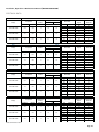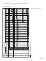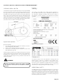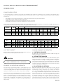
1
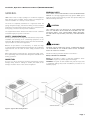
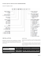
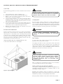
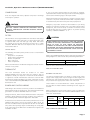
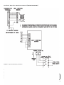
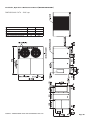
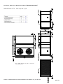
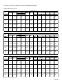
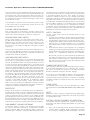
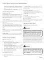
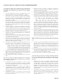
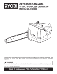
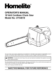
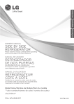
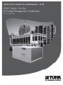
Installation, Operation & Maintenance Manual (IOPCKKS60220510B1)
Contents
GENERAL
Safety considerations............................................................ 3
Inspection ............................................................................ 3
Renewal parts ....................................................................... 3
Product nomenclature........................................................... 4
INSTALLATION
Limitations ........................................................................... 4
Location ................................................................................ 5
Rigging and handling............................................................. 5
Clearances ........................................................................... 5
Ductwork ............................................................................. 5
Fixed outdoor air intake damper ........................................... 6
Condensate drain .................................................................. 6
Compressors ......................................................................... 7
Filters .................................................................................... 7
Service access ...................................................................... 7
Thermostat .......................................................................... 7
Power and control wiring ...................................................... 7
Optional electric heat............................................................ 7
Phasing ................................................................................ 8
Product data ......................................................................... 9
Dimensions and clearances (DMS 190) ................................. 10
Dimensions and clearances (DMS 240, 260, 340) ................. 11
Drive and pulley data ............................................................ 12
Electrical data (DMS 190) ...................................................... 13
Electrical data (DMS 240, 260, 340) ...................................... 14
Fan performance data ........................................................... 15
Checking supply air cfm ........................................................ 16
SAFETY
Terminology .......................................................................... 16
Operational safety ................................................................. 16
Use and Operation ................................................................ 16
Adherence to warnings ......................................................... 16
Staff training ......................................................................... 16
Use of the unit ...................................................................... 16
Recommended safety practices ............................................ 17
Applicable standards of EEC machinery directive ................. 17
OPERATION
Sound power ratings ............................................................. 17
Volt free contact ................................................................... 18
Sequence of operations ........................................................ 18
Cooling operation errors ....................................................... 19
High pressure limit switch ..................................................... 19
Low pressure limit switch...................................................... 19
Freezestat ............................................................................. 19
Low ambient cooling............................................................. 19
Safety controls ...................................................................... 19
Compressor protection ......................................................... 19
Flash codes ........................................................................... 19
Reset .................................................................................... 19
Electric heating sequence of operations ............................... 19
Heating operation errors ....................................................... 20
START UP
Restart check list................................................................... 20
Operating instructions........................................................... 20
Post start check list ............................................................... 20
Shut down............................................................................. 20
Belt drive blower ................................................................... 20
TROUBLE SHOOTING
Cooling trouble shooting guide ............................................. 20
Unit flash codes .................................................................... 23
MAINTENANCE
Every month.......................................................................... 23
Every three months............................................................... 23
Every six months................................................................... 23
Every twelve months............................................................. 23
Page 2
Installation, Operation & Maintenance Manual (IOPCKKS60220510B1)
GENERAL
YORK Saber units are single package air conditioners equipped
with optional factory installed electric heaters and designed for
outdoor installation on a rooftop or steel structure.
The units are completely assembled on a rigid base frame. All
piping, refrigerant charge, and electrical wiring is factory installed
and tested. The units require electric power, duct connections and
drain piping connections at the point of installation.
The supplemental electric heaters have nickel-chrome elements
and utilize single point power connection.
SAFETY CONSIDERATIONS
RENEWAL PARTS
Refer to YORK® USER’S MAINTENANCE and SERVICE INFORMATION
MANUAL. It is strongly suggested that only genuine YORK® Spare
Parts are used to ensure long life, product and operator safety and
efficient working of the unit.
CAUTION
THIS PRODUCT MUST BE INSTALLED IN STRICT COMPLIANCE
WITH THE ENCLOSED INSTALLATION INSTRUCTIONS AND ANY
APPLICABLE LOCAL, STATE, AND NATIONAL CODES INCLUDING,
BUT NOT LIMITED TO, BUILDING, ELECTRICAL, AND MECHANICAL
CODES.
Due to system pressure, moving parts and electrical components,
installation and servicing of air conditioning equipment can be
hazardous. Only qualified, trained, service personnel should install,
repair, maintain or service this equipment.
WARNING
Observe all precautions in the literature, on labels and tags
accompanying the equipment whenever working on air conditioning
equipment. Be sure to follow all other safety precautions that
apply.
Wear safety glasses and work gloves, and follow all safety codes.
Use a quenching cloth and have a fire extinguisher available for all
brazing operations.
INSPECTION
As soon as a unit is received, it should be inspected for possible
damage during transit. If damage is evident, the extent of the
damage should be noted on the carrier’s freight bill.
IMPROPER INSTALLATION MAY CREATE A CONDITION WHERE
THE OPERATION OF THE PRODUCT COULD CAUSE PERSONAL
INJURY OR PROPERTY DAMAGE.
Installer should pay particular attention to the words :
NOTE, CAUTION and WARNING.
NOTES are intended to clarify or make the installation easier.
CAUTIONS are given to prevent equipment damage.
WARNINGS are given to alert installer that personal injury and/
or equipment damage may result if installation procedure is not
handled properly.
Figure 1: Typical Unit Configuration
Page 3
Installation, Operation & Maintenance Manual (IOPCKKS60220510B1)
PRODUCT NOMENCLATURE
INSTALLATION
LIMITATIONS
Read these instructions before continuing this appliance
installation. This is an outdoor combination heating and cooling
unit. The installer must assure that these instructions are made
available to the consumer and with instructions to retain them for
future reference.
These units must be installed in accordance with the applicable
national and local safety codes. (Refer to Unit Application Data
table).
Unit Model Number
Voltage Variation (min/max)
Supply Airflow Rate (min/max)
On-Coil Wet Bulb Temperature (min/max)
Ambient Air Temperature (min/max)
If components are to be added to a unit to meet local codes, they
are to be installed at the dealer’s and/or the customer’s expense.
Size of unit for proposed installation should be based on heat loss/
heat gain calculation.
DMS 190
220V/3Ph/60Hz
380V/3Ph/60Hz
460V/3Ph/60Hz
cfm
°F
°F
DMS 240
DMS 260
DMS 340
200/240
342/418
414/506
4800/7200
5400/8400
6000/9000
57/72
50/125 (30/125 with Low Ambient Option)
7000/11500
Table 1: Unit Application Data
Page 4
Installation, Operation & Maintenance Manual (IOPCKKS60220510B1)
LOCATION
Use the following guidelines to select a suitable location for these
units :
1.
2.
3.
4.
5.
6.
Unit are designed for outdoor installation only.
Condenser coils must have an unlimited supply of air.
Where a choice of location is possible, position the unit on
either north or east side of building.
For ground level installation, use a level concrete slab with a
minimum thickness of 4 inches. The length and width should
be at least 6 inches greater than the unit base rails. Do not tie
slab to the building foundation.
Roof structures must be able to support the weight of the unit
and its options and/or accessories. Unit must be installed on a
solid level roof curb or appropriate angle iron frame.
Maintain level tolerance to 1/2 inch maximum across the
entire length or width of the unit.
RIGGING AND HANDLING
WARNING
BEFORE LIFTING A UNIT, MAKE SURE THAT ALL PANELS
ARE IN PLACE AND THAT ITS WEIGHT IS DISTRIBUTED
EQUALLY ON ALL CABLES SO IT WILL LIFT EVENLY
CLEARANCES
All units require certain clearances for proper operation and
service. Installer must make provisions for adequate ventilation
air in accordance with applicable provisions of the local building
codes. Refer to Dimensions and Clearances. Refer Figure 8 for the
clearances required for servicing, and proper unit operation.
WARNING
Exercise care when moving the unit. Do not remove anypackaging
until the unit is near the place of installation. Rig the unit by
attaching chain or cable slings to the round lifting holes provided
in the base rails. Spreaders, whose length exceeds the largest
dimension across the unit, MUST BE USED. Refer to Figure 3. Units
may also be moved or lifted with a forklift, from the side only,
provided that an accessory skid is used.
DUCTWORK
LENGTH OF FORKS MUST BE A MINIMUM OF 90”. Refer
to the Product Data Table 5 for unit weights.
A closed return duct system should be used. This should not
preclude use of outdoor fresh air intake.
DO NOT PERMIT OVERHANGING STRUCTURES OR
SHRUBS TO OBSTRUCT OUTDOOR AIR DISCHARGE
OUTLET.
The supply and return air duct connections at the unit should
be made with flexible joints to minimize noise. The supply and
return air duct systems should be designed for the CFM and static
requirements of the job. They should NOT besized to match the
dimensions of the duct connections on the unit.
WARNING
WHEN FASTENING DUCTWORK TO SIDE DUCT FLANGES
ON UNIT, INSERT SCREWS THROUGH DUCT FLANGES
ONLY. DO NOT INSERT SCREWS THROUGH CASING.
OUTDOOR DUCTWORK MUST BE INSULATED AND
WATERPROOFED.
Refer to Dimensions and Clearances Figure 8 for information
concerning supply and return air duct openings.
FIXED OUTDOOR AIR INTAKE DAMPER
This damper is shipped inside the return air compartment. It is
completely assembled and ready for installation. Refer to the
Fixed Outdoor Damper Figure 3.
Figure 2: Typical Rigging
Gasketing and mounting screws are provided in a parts bag.
Adjusting the damper to the desired air flow may be done after
installation by opening or closing dampers with handle.
Damper provides maximum of 25% fresh air when fully opened.
Page 5
Installation, Operation & Maintenance Manual (IOPCKKS60220510B1)
CONDENSATE DRAIN
Plumbing must conform to local codes. Use a sealing compound
on male pipe threads. Install a condensate drain line from the one
inch FPT female connection on the unit to an open drain.
NOTE : The condensate drain operates in a negative pressure
in the cabinet. The condensate drain line MUST be trapped
to provide proper drainage. See Figure 4.
Figure 3: Fixed Outdoor Air Damper
Figure 4: Recommended drain piping
Figure 5: Four Point Load
Figure 6: Six Point Load
Page 6
Installation, Operation & Maintenance Manual (IOPCKKS60220510B1)
COMPRESSORS
Units are shipped with factory adjusted compressor mountings
and ready for operation.
If any of the wire supplied with the unit must be replaced,
replacement wire must be of the type shown on the wiring diagram
and the same minimum gauge as the replaced wire.
Electrical line must be sized properly to carry the load. Use copper
conductors only. Each unit must be wired with a separate branch
circuit fed directly from the meter panel and properly fused.
CAUTION
DO NOT LOOSEN COMPRESSOR MOUNTING BOLTS.
REMOVE COMPRESSOR SHIPPING BRACKETS BEFORE
START-UP.
Emergency stop button should be field installed as per wiring
diagram. The activator should be red in colour with a yellow outline
background, and should be easily accessible. The device should
be self latching type and contacts must be of positive opening
operation, certified to EN60947 - 5 - 1.
FILTERS
Two inch filters can be supplied with each unit. Filters must always
be installed ahead of the evaporator coil and must be kept clean
or replaced with same size and type. Dirty filters will reduce
the capacity of the unit and will result in frosted coils or safety
shutdown. Minimum filter area and required sizes are shown in
Product Data Table 4.
SERVICE ACCESS
The following removable panels provide access to all serviceable
components :
t Compressor compartment
t Electric Heat compartment
t Blower compartment
t Main control box
t Filter compartment
Refer to the Dimensions and Clearances Figuress 8 & 9 for location
of these access panels.
THERMOSTAT
The room thermostat should be located on an inside
wallapproximately 56 inches above the floor where it will not
besubject to drafts, sun exposure or heat from electrical fixtures
or appliances. Follow manufacturers instructions enclosed with
thermostat for general installation procedure. A minimum of seven
color coded insulated wires (#18 AWG) should be used to connect
thermostat to unit.
POWER AND CONTROL WIRING
Field wiring to the unit must conform to provisions of the National
Electrical Code and/or local ordinances. The unit must be electrically
grounded in accordance with NEC and/or local codes.
Voltage tolerances, which must be maintained at the compressor
terminals, during starting and running conditions, are indicated on
the unit Rating Plate and the Unit Application Data table.
A fused disconnect switch should be field provided based on the
tabulated rating, with a short circuit capacity of 10K or more, for
the unit. The switch must be separate from all other circuits. Wire
entry at knockout openings require conduit fittings to comply with
local codes. Refer to the Dimensions and Clearances Figures 8 for
installation location.
CAUTION
WHEN CONNECTING ELECTRICAL POWER AND CONTROL
WIRING TO THE UNIT, WATERPROOF TYPE CONNECTORS
MUST BE USED SO THAT WATER OR MOISTURE
CANNOT BE DRAWN INTO THE UNIT DURING NORMAL
OPERATION. THE ABOVE WATERPROOFING CONDITIONS
WILL ALSO APPLY WHEN INSTALLING A FIELD SUPPLIED
DISCONNECT SWITCH.
Refer to Typical Wiring Diagram, Figure 7 and to the appropriate unit
wiring diagram for control circuit and power wiring information.
Wire Size
Maximum Length (1)
18 AWG
150 feet
From the unit to the thermostat and back to the unit
Table 2: Control Wire Sizes
OPTIONAL ELECTRIC HEAT
The factory-installed heaters are wired for single point power
supply. Power supply need only be brought into the single point
terminal block and thermostat wiring to the low voltage terminal
strip located in the upper portion of the unit control box.
These heaters are located within the central compartment of
the unit with the heater elements extending into the supply air
chamber.
Refer to Figure 8 for access panel location. Fuses are supplied by
the factory. Refer to Table 3 for minimum CFM limitations and to
Table 5 for electrical data.
Nominal
Heater Size
18 kW, 2 stages
36 kW, 2 stages
V / 3Ph /
60Hz
220/230,
380,460
Minimum CFM
DMS-190
DMS-240
DMS-260
DMS-340
4800
5400
6000
7000
Table 3: Minimum CFM Limitation
Page 7
Installation, Operation & Maintenance Manual (IOPCKKS60220510B1)
FIGURE 7 : Typical Field Wiring Schematic
PHASING
YORK® Saber units are properly phased at the factory. Check for
proper compressor rotation. If the blower or compressors rotate
in the wrong direction at start up, the electrical connection to the
unit is misphased. Change the incoming line connection phasing
to obtain proper rotation. (Scroll compressors operate in only
one direction. If the scroll is misphased). DMS 190 models have
reciprocating compressors.
CAUTION
SCROLL COMPRESSORS REQUIRE PROPER ROTATION TO
OPERATE CORRECTLY. UNITS ARE PROPERLY PHASED
AT THE FACTORY. DO NOT CHANGE THE INTERNAL
WIRING TO MAKE THE BLOWER, CONDENSER FANS, OR
COMPRESSOR ROTATE CORRECTLY.
Page 8
Installation, Operation & Maintenance Manual (IOPCKKS60220510B1)
PRODUCT DATA
MODEL DMS
Ratings @ARI
Conditions
Electric
Heating
Capacities
EER
Btu/W
190
9.3
11.8
11.9
9.4
Capacity
MBH
kW
190.7
55.9
246.5
259
322.1
HP
kW
20.5
15.3
19.7
20.8
35.6
Option 1
MBH
kW
61.4
18.0
61.4
61.4
61.4
Option 2
MBH
kW
122.8
36.0
122.8
122.8
122.8
Compressor
Power Input
Area
Fin Spacing
ft²
m²
fpi
mm
13.33
1.24
Fin Spacing
Area
Blower Fan &
Motor
fpi
mm
ft²
m²
12
2.1
24.3
2.3
Condenser
Fan & Motor
Compressor
Refrigerant
std
hp
kW
hp
kW
4.0
3.0
5.5
4.0
xtd
Type
Quantity
Motor Type
Motor size
Quantity
Type
Quantity
Type
Charge Cir A
Charge Cir B
Height
Dimensions
Width
Length
h x l x d - Qty
Filters
h x l x d - Qty
Weights
Basic Unit
Table 4: Product data
#
hp
kW
#
#
lbs
kgs
lbs
kgs
inches
mm
inches
mm
inches
mm
inches
mm
inches
mm
lbs
kg
23.6
2.2
23.6
2.2
10
2.5
Copper / Aluminum Louvered
12
2.1
26.7
2.5
Forward Curved Centrifugal - DIDW
1
4 Pole, Class F Insulation, Totally Enclosed Fan Cooled, IP54, 1700 rpm
12
2.1
5.5
5.5
4.0
4.0
7.5
7.5
5.5
5.5
4 Blade Heavy Duty Propeller Fan
2
6 Pole, Class F Insulation, Totally Enclosed Fan Cooled, IP54 1100 rpm
1.5
1.1
2
Hermetic Scroll
Hermetic Reciprocating
2
R - 22
7.5
5.5
10.0
7.5
Fan Type
Fan Quantity
Motor Type
Motor
Size
340
17.3
1.6
Tube / Fins
Condenser
Coil
260
Copper / Aluminum Louvered
Tube / Fins
Evaporator
Coil
240
12.2
5.5
11
5
52.5
1333.0
77.8
1976.0
89.0
2271.0
20 x 24 x 2 - 4#
508 x 610 x 50 - 4#
14
1.8
15
6.8
15
7.7
17
7.7
17
7.7
51.3
1303.0
89.1
2263.0
105.4
2677.0
20 x 24 x 2 - 3#
508 x 610 x 50 - 3#
24 x 24 x 2 - 3#
610 x 610 x 50 - 3#
18
8.2
18
8.2
1890
859
2025
920
2100
955
---1463
665
Page 9
Installation, Operation & Maintenance Manual (IOPCKKS60220510B1)
DIMENSIIONAL DATA - DMS 190
Clearances
Front (Control Panel & Comp Access)
Left (Filter Access)
Right (Condenser Coil)
Above (Condenser Air Discharge)
inches
36
30
36
72
mm
914
762
914
1829
FIGURE 8 : DIMENSIONAL DATA AND CLEARANCES DMS 190
Page 10
Installation, Operation & Maintenance Manual (IOPCKKS60220510B1)
DIMENSIIONAL DATA - DMS 240, 260 & 340
Note: DMS Models 240, 260 & 340 have
same dimensions.
FIGURE 9 : DIMENSIONAL DATA AND CLEARANCES DMS MODELS 240, 260 AND 340
Page 11
Installation, Operation & Maintenance Manual (IOPCKKS60220510B1)
DRIVE AND PULLEY DATA
Low Static Drive Set
MODEL
Motor Pulley
Bush
DMS
Pitch Dia.
min
max
mm
Fan Pulley
Bush
Pitch Dia
rpm range
rpm setting Centre Dist. Belt Size
mm
min
max
-
mm
190
VAR 108 A1 1210 x 28mm
78
102
SPA-224 1 2012 x 25mm
224
609
797
710
597
1687
240
VAR 108 A1 1210 x 28mm
78
102
SPA-212 1 2012 x 25mm
212
644
842
750
597
1668
260
VAR 108 A1 1210 x 28mm
78
102
SPA-280 1 2012 x 25mm
280
488
638
600
597
1775
340
VAR 139 A1 1610 x 38mm
109
133
SPA-355 1 2012 x 25mm
355
537
656
680
597
1942
Standard Drive Set
MODEL
Motor Pulley
Bush
DMS
Pitch Dia.
min
max
mm
Fan Pulley
Bush
Pitch Dia
rpm range
rpm setting Centre Dist. Belt Size
mm
min
max
-
mm
190
VAR 108 A1 1210 x 28mm
78
102
SPA-170 1 1610 x 25mm
170
803
1050
920
597
1432
240
VAR 108 A1 1210 x 28mm
78
102
SPA-160 1 1610 x 25mm
160
853
1116
985
597
1432
260
VAR 108 A1 1210 x 28mm
78
102
SPA-212 1 2012 x 25mm
212
644
842
705
597
1668
340
VAR 177A1 2012 x 38mm
149
171
SPA-3551
355
735
843
790
597
2003
Motor Pulley
Pitch Dia.
min
max
mm
2012 x 25mm
High Static Drive Set
MODEL
Bush
DMS
Fan Pulley
Bush
Pitch Dia
rpm range
mm
min
max
rpm setting Centre Dist. Belt Size
-
mm
190
VAR 108 A1 1210 x 28mm
78
102
SPA-150 1 1610 x 25mm
150
910
1190
1050
597
1571
240
VAR 146 A1 1610 x 38mm
116
140
SPA-200 1 2012 x 25mm
200
1015
1225
1120
597
1709
260
VAR 146 A1 1610 x 38mm
116
140
SPA-265 1 2012 x 25mm
265
766
925
850
597
1811
340
VAR 146 A1 1610 x 38mm
116
140
SPA-250 1 2012 x 25mm
250
812
980
900
597
1788
Table 5: Drive and Pulley data
Page 12
Installation, Operation & Maintenance Manual (IOPCKKS60220510B1)
ELECTRICAL DATA
Model
Voltage
220 V / 3Ph / 60 Hz
380 V / 3Ph / 60 Hz
460 V / 3Ph / 60 Hz
DMS-190
Compressors
Condenser Fan
Motors
RLA Each
LRA Each
FLA Each
25.9
140.0
5.4
15.1
11.6
102.0
90.0
3.1
3.2
Supply Blower Motor
Standard
Extended
FLA
11.4
14.2
6.4
8.2
5.7
7.5
220 V / 3Ph / 60 Hz
380 V / 3Ph / 60 Hz
460 V / 3Ph / 60 Hz
Compressors
Condenser Fan
Motors
RLA Each
LRA Each
FLA Each
29.5
237.0
5.4
17.5
14.3
160.0
130.0
3.1
3.2
Supply Blower Motor
Standard
Extended
FLA
14.2
19.0
8.2
11.0
7.5
10.0
220 V / 3Ph / 60 Hz
380 V / 3Ph / 60 Hz
460 V / 3Ph / 60 Hz
Compressors
Condenser Fan
Motors
RLA Each
LRA Each
FLA Each
29.5
237.0
5.4
17.5
14.3
160.0
130.0
3.1
3.2
Supply Blower Motor
Standard
Extended
FLA
14.2
19.0
8.2
11.0
7.5
10.0
Model
Voltage
220 V / 3Ph / 60 Hz
380 V / 3Ph / 60 Hz
460 V / 3Ph / 60 Hz
Maximum Fuse
Breaker Size
Amperes
89.4
Amperes
125
kW
-
Amperes
-
18.0
47.2
89.4
125
36.0
94.5
116.3
150
-
-
52.0
70
18.0
27.4
52.0
70
36.0
54.7
67.3
90
-
-
42.4
60
18.0
22.6
42.4
60
36.0
45.2
57.4
80
Minimum Circuit
Amperes
Maximum Fuse
Breaker Size
Electric Heater
kW
-
Amperes
-
Amperes
105.1
Amperes
150
18.0
47.2
105.1
150
36.0
94.5
119.5
150
-
-
62.0
80
18.0
27.4
62.0
80
36.0
54.7
69.1
90
-
-
52.3
70
18.0
22.6
52.3
70
36.0
45.2
59.1
80
Minimum Circuit
Amperes
Maximum Fuse
Breaker Size
Amperes
150
DMS-260
Model
Voltage
Minimum Circuit
Amperes
DMS-240
Model
Voltage
Electric Heater
Electric Heater
kW
-
Amperes
-
Amperes
105.1
18.0
47.2
105.1
150
36.0
94.5
119.5
150
-
-
62.0
80
18.0
27.4
62.0
80
36.0
54.7
69.1
90
-
-
52.3
70
18.0
22.6
52.3
70
36.0
45.2
59.1
80
Minimum Circuit
Amperes
Maximum Fuse
Breaker Size
DMS-340
Compressors
Condenser Fan
Motors
RLA Each
LRA Each
FLA Each
40.8
255.0
5.4
26.4
20.4
155.0
135.0
3.1
3.2
Supply Blower Motor
Standard
Extended
FLA
19.0
11.0
10.0
25.2
15.6
13.6
Electric Heater
kW
-
Amperes
-
Amperes
141.2
Amperes
200
18.0
47.2
141.2
200
36.0
94.5
141.2
200
-
-
89.4
125
18.0
27.4
89.4
125
36.0
54.7
89.4
125
-
-
71.8
90
18.0
22.6
71.8
90
36.0
45.2
71.8
90
Table 6: Electrical data
Page 13
3
4
15 / 15
15 / 15
18 / 18
18 / 18
190
240
260
340
7.5
5.5
5.5
4
kW
External Static Pressure in.wg. [Pa]
5.33
2.43
11500 5427 735 4.98 769
4011 573 2.18 617
8500
1.56
3.72
3303 512 1.37 560
7000
2.81
2.12
1.56
1.11
4.03
2.87
2.00
1.33
2.22
1.68
1.19
0.73
kW
10000 4719 656 3.41 696
4247 601 2.56 642
9000
3303 512 1.37 560
7000
3775 553 1.88 600
2831 468 0.95 521
6000
8000
3964 906 3.80 944
3020 727 1.81 776
6400
8400
2548 644 1.17 701
5400
3492 814 2.67 857
3067 772 2.03 820
6500
7400
2737 709 1.50 761
2360 639 1.03 699
5000
5800
1888 560 0.61 628
4000
RPM kW RPM
L/s
803
731
658
606
683
640
606
566
982
900
824
754
866
811
753
691
RPM
940
870
806
910
859
806
751
RPM
3.32
2.39
1.65
2.62
2.03
1.46
0.97
kW
981
914
855
952
905
856
810
RPM
957
902
995
948
904
867
RPM
992
952
922
RPM
5.69
4.00
2.66
1.75
3.07
2.33
1.75
1.26
834
767
699
644
720
680
644
611
6.01
4.28
2.90
1.93
3.31
2.55
1.93
1.42
865
802
732
682
754
717
682
656
999
975
RPM
RPM
kW
RPM
kW
2.10 1044 2.29 1090 2.48
1.58 1027 1.75 1078 1.93
kW
2.50 1033 2.68 1075 2.87 1116 3.07
1.93
1.42
kW
2.75
1.94
999
947
992
2.28 1035 2.47 1079 2.66
2.93 1038 3.10 1077 3.28 1116 3.47
2.11
2.98 1034 3.16 1073 3.33 1111 3.52 1149 3.72
2.34
1.76
1.26
kW
6.33
4.55
3.12
2.10
3.55
2.75
2.10
1.60
896
832
766
720
789
750
720
701
6.65
4.81
3.34
2.30
3.79
2.96
2.30
1.78
924
862
800
758
819
783
758
747
6.96
5.08
3.56
2.50
4.02
3.16
2.50
2.00
952
892
830
796
848
816
796
792
-
7.26
5.34
3.78
2.70
4.24
3.37
2.70
2.23
-
-
919
860
836
877
849
836
837
-
-
5.59
4.00
2.95
4.47
3.60
2.95
2.48
-
-
945
890
875
906
882
875
881
0
-
5.84
4.22
3.20
4.70
3.83
3.20
2.73
0.00
3.55 1020 3.77 1058 3.99 1096 4.21 1132 4.40 1167 4.58
2.58
1.79
2.80
2.18
1.60
1.11
kW
4.26 1019 4.50 1055 4.76 1091 5.02 1126 5.28
3.08
2.19
1.49
2.42
1.86
1.32
0.84
kW
0.20 [50] 0.40 [100] 0.60 [149] 0.80 [199] 1.00 [249] 1.20 [299] 1.40 [349] 1.60 [399] 1.80 [448] 2.00 [498]
cfm
Air Flow
Rate
Shaded area represent upsize motors
5.5
4
kW
Size
DMS
Optional
Motor
Standard
Fan
Model
Installation, Operation & Maintenance Manual (IOPCKKS60220510B1)
FAN PERFORMANCE
Table 7: Fan Performance data
Page 14
Installation, Operation & Maintenance Manual (IOPCKKS60220510B1)
CHECKING SUPPLY AIR CFM
The RPM of the supply air blower will depend on the required CFM,
the unit accessories or options and the static resistances of both
the supply and the return air duct systems. With this information,
the RPM for the supply air blower and the motor pulley adjustment
(turns open) can be determined from the Fan Performance Data
Tables. High speed drive accessories (containing a smaller blower
pulley and a shorter belt) are available for applications requiring
the supply air blower to produce higher CFM and/or higher static
pressures. Refer to the Drive and Pulley Data Table 6.
Safety
This section of the IOM covers Safety Aspects applicable to
the York DMS Saber Roof Top Air Conditioners. Adherence to
the instructions detailed hereunder, will ensure the safety of
the operators, prevent damage to the equipment and prevent
accidents.
Figure 10: Belt adjustment
Note the following :
1. The supply air CFM must be within the limitations shown in
the Unit Application Data Table 1.
2. Pulleys can be adjusted in half turn increments.
3. The tension on the belt should be adjusted as shown inthe
Belt Adjustment Figure 10.
Start the supply air blower motor. Adjust the resistances in both the
supply and the return air duct systems to balance the air distribution
throughout the conditioned space. The job specifications may
require that this balancing be done by someone other than the
equipment installer.
WARNING
FAILURE TO PROPERLY ADJUST THE TOTAL SYSTEM
AIR QUANTITY CAN RESULT IN EXTENSIVE BLOWER
DAMAGE
Figure 11: Unit Nameplate
TERMINOLOGY
The internal section of the unit adjacent to moving parts and
electrical parts or devices is considered as the ‘danger zone’.
Prior to gaining access to these parts, it is necessary to acquire
the proper tools to deactivate the safety devices. The operators
are responsible for transport, installation, start up, service and
maintenance, including cleaning and trouble shooting.
OPERATIONAL SAFETY
York DMS Saber Roof Top Packages Air Conditioners in conformance
to the highest standards of operational as well as operator safety.
Nevertheless, hazards may occur if the units are used for purposes
other than the designed use(s), Units are operated by untrained
staff and / or Units are not operated in conformance with general
standards prevalent in the industry.
Page 15
Installation, Operation & Maintenance Manual (IOPCKKS60220510B1)
OPERATION AND USE OF THE UNIT IN
CONFORMANCE WITH GENERAL STANDARDS
AND PROVISIONS
3. Warnings against coming into contact with electrical parts.
YORK® DMS Saber Roof Top Packaged Air Conditioners are
designed for and are able to cool, heat, filter air and operate in
the fan mode. Any other use is considered not in conformity with
general provisions.
The manufacturer is not responsible for any resulting damages.
All responsibility resulting from such non conformity rests with
the user. In order to use the unit according to general provisions
proper instructions for installation, exercise and transport must be
observed.
Installation and start up of the unit must satisfy the national codes
and standards having legal validity in the country of use. The
user is responsible for compliance with standards. Additionally,
any type of work that may compromise safety should be avoided.
Arbitrary transformations or modifications to the unit by the user
or operator are not permitted and nullify the warranty of the
manufacturer. The manufacturer will also not be responsible for
any damages to the equipment, to property or to personnel.
All warnings and signs regarding the units must be absolutely
observed.
STAFF TRAINING
ADHERENCE OF THE USER / OPERATOR TO THE
WARNINGS AND OTHER INSTRUCTIONS
The unit should be started up and serviced (routine and corrective
maintenance) by authorized and trained staff only. This staff must
be informed about possible hazards regarding :
Clear signs are placed at appropriate locations on the unit
showing:
t&MFDUSJDBMDPOOFDUJPOT
t1JQJOHDPOOFDUJPOT
t%VDUDPOOFDUJPOT
t4UBSUVQ
1.
Prohibition to repair or adjustments during motion.
These operations must be executed only by trained persons. who,
on behalf of the user, attend to control and to perform extraordinary
/ ordinary maintenance of the unit. It is necessary to establish
and to respect the responsibilities for control and maintenance to
guaranty safety, without confusion.
USE OF THE UNIT
The unit must be started up only by means of proper safety
devices. The installer is obliged to install the unit according to
installation plans and conditions. Only authorized persons must
operate the unit.
2. Obligation to turn off the power before opening the access
doors.
The staff in charge is obliged to immediately inform the user of
any changes that may compromise safety. For this reason it is
necessary to inspect for eventual anomalies or damages at least
once a week.
The user or operator must never dismount and deactivate safety
devices. If these have to be removed for maintenance, all safety
devices must be reinstalled at their correct location once the
maintenance is complete. For all operations of maintenance, the
power source must be locked out.
If it is necessary to undertake maintenance activities, the fan must
be switched off, isolated and allowed to run down.
Page 16
Installation, Operation & Maintenance Manual (IOPCKKS60220510B1)
RECOMMENDED SAFETY PRACTICES
This publication explains the proper use and installation of equipment in order to warn operating and maintenance personnel of the
commonly recognized dangers associated with this equipment. In addition to following the manufacturer’s installation instructions, care
must be taken to ensure compliance with federal, state and local rules, regulations, codes and standards.
Applicable standards of EEC Machinery Directive
1.1.1 Defination
1.1.2a,b,c,d,e,f
Measures taken
Ref to Harmonised procedure
Referred in Instruction Manual
Principles of safety Integration
Refer to "safety considerations" in Instruction Manual
1.1.3 Materials and products
Refer to Instruction manual
1.1.5 Desgin of machinery to facilitate its handling
Design of unit with basement for lifting by forklift or rope, locking
of compressor fixings during transport
UNI EN 12100-1& 12100-2
1.2.1 Safety and Reliability of control system
Refer to Electrical schematic pasted inside the unit
UNI EN 12100-1& 12100-2
1.2.2 Control Devices
control devices are positioned outside danger zone, Emergency
stop to be provided by customer, loop for same provided &
Described in IOM
UNI EN 12100-1& 12100-2
1.2.3 starting
For Start/Restart, Voluntary actuation required for change of
temperature settings, Machine doesn’t have several starting
controls
UNI EN 12100-1& 12100-2
1.2.4 stopping devices
Refer to Electrical schematic pasted inside the unit, Normal
stopping can be activated by main disconnect switch, its in
customer scope
UNI EN 12100-1& 12100-2
1.2.4 a Emergency stop
Customer's scope, Loop for emergency stop is provided in
Electrical schematic
UNI EN 12100-1& 12100-2
1.2.6 Failure of the power supply
Failure o power supply will stop the machine, once power is
restored, voluntary actuation is required to restart.
UNI EN 12100-1& 12100-2
1.2.7 failure of the control circuit
Machine doesn’t start without manual interaction, stop has got
priority over start
UNI EN 12100-1& 12100-2
1.2.8 Software
Refer to IOM for details of Simplicity Programming
UNI EN 12100-1& 12100-2
1.3.2 Risk of breakup during operation
operating conditions stated on the as built drawings, frequency of
maintenance listed in the instruction manual, Fixed guards are
provided so that breakage will be contained.
UNI EN 12100-1& 12100-2
1.3.4.Risks due to surfaces, edges or angles.
covers will be put on sharp edges of screws
UNI EN 12100-1& 12100-2
access door openable with special tools , written warnings fitted
on access door.
UNI EN 12100-1& 12100-2
1.5.1 Electricity supply
Refer to page 7 of IOM, + 10% voltage fluctuation limit specified
UNI EN 12100-1& 12100-2
1.3.7 Preventation of risks related to moving parts.
1.3.8 choice of protection against risks related to moving parts
1.4.1 General Requirements
1.4.2.1 Fixed Gurards
1.5.4 Error of fittings
Refer to IOM
UNI EN 12100-1& 12100-2
1.5.8 Noise
Refer to IOM for Noise data
UNI EN 12100-1& 12100-2
1.5.9 Vibration
Refer to IOM
UNI EN 12100-1& 12100-2
1.6.1 Machinery maintenance
Refer to page 19 of Instruction Manual
UNI EN 12100-1& 12100-2
1.6.2 Access to operating position and servicing points
Refer to Unit dimensional drawing in IOM
UNI EN 12100-1& 12100-2
UNI EN 12100-1& 12100-2
1.6.3 Isolation of energy sources
Refer to IOM for warning Notes
1.6.4 Operator intervention
Work instruction of safety procedures manual
UNI EN 12100-1& 12100-2
1.6.5 Cleaning of internal part
Refer to maintenance schedule in IOM
UNI EN 12100-1& 12100-2
1.7.1 Warning devices
Written warning in proximity to electrical and rotating pars, loops
for warning devices is provided refer to wiring schematic
UNI EN 12100-1& 12100-2
1.7.2 warning of residual risk
Refer to IOM
UNI EN 12100-1& 12100-2
1.7.3 Marking
Marking on metal name plate displayed on the outside fan
section access door & on control panel door
UNI EN 12100-1& 12100-2
I t ll ti
d
i t
h db k A b ilt d
i
Page 17
Installation, Operation & Maintenance Manual (IOPCKKS60220510B1)
OPERATION
SOUND POWER RATINGS
A sound power level is a measure of the total noise radiated by the machine in all directions. It is a property of the machine and is
essentially independent of the measuring environment. Sound power levels are useful to equipment manufacturers, buyers, installers,
and users for:
t
t
t
t
Calculating the sound pressure level from a machine at a given distance in a given environment.
Comparing the noise output from different machines.
Setting specifications for the maximum permitted noise from a machine.
Comparing machines before and after modifications to reduce the noise.
Sound power is measured in watts or picowatts, and sound power levels are traditionally given in decibels (dB re 1pW). Refer table 8 for
sound power level of whole unit and table 9 for sound power levels of fan only.
Blower
ESP
Model No.
CFM
DMS-190
5800
1
DMS-240
7400
1
DMS-260
8000
DMS-340
10000
IWG RPM
Octave Band Frequency Hz
63
125
250
500
1000
2000
4000
8000
919
2.94
71.60
74.62
81.62
83.62
84.62
81.62
75.62
72.62
89.62
981
4.65
73.45
76.45
83.45
85.45
86.45
83.45
77.45
74.45
91.45
1
715
3.67
71.00
74.00
81.00
83.00
84.00
81.00
75.00
72.00
89.0
1
797
6.06
74.87
77.87
84.87
86.87
87.87
84.87
78.87
75.87
92.87
Ref 1 x 10^-12 watts
Model
CFM
dB(A)
BHP
TABLE 8 : SOUND POWER LEVELS (DMS SABER UNITS)
ESP
Blower
RPM
Kw
Octave Band Mid Frequency (HZ)
BHP
63
125
250
500
1K
2K
4K
8K
Total
(dBA)
DMS-190
5800
1
919
2.2
2.9
68.5
71.5
78.5
80.5
81.5
78.5
72.5
69.5
86.5
DMS-240
7400
1
981
3.47
4.7
72.5
75.5
82.5
84.5
85.5
82.5
76.5
73.5
90.5
DMS-260
8000
1
715
2.74
3.7
69.8
72.8
79.8
81.8
82.8
79.8
73.8
70.8
87.8
DMS-340
10000
1
797
4.52
6.1
74.4
77.4
84.4
86.4
87.4
84.4
78.4
75.4
92.4
TABLE 9 : SOUND POWER LEVELS (STANDARD FANS)
VOLT FREE CONTACT
COOLING SEQUENCE OF OPERATION
All Saber units are supplied with Volt free contact, Refer to lectrical
wiring schematic that are pasted inside the unit.
1. CONTINUOUS BLOWER
By setting the room thermostat fan switch to “ON” the supply air
blower will operate continuously.
2. INTERMITTENT BLOWER
CAUTION
HOOK UP EMERGENCY SHUT - OFF BUTTON
SEQUENCE OF OPERATIONS OVERVIEW
With the room thermostat fan switch set to “AUTO” and the system
switch set to either the “AUTO” or “HEAT” settings, the blower is
energized whenever a cooling or heating operation is requested.
The blower is energized after any specified delay associated with
the operation. When energized, the indoor blower has a minimum
run time of 30 seconds. Additionally, the indoor blower has a delay
of 10 seconds between operations.
3. NO OUTDOOR AIR OPTIONS
For these units, the thermostat makes a circuit between “R” and
“Y1” for the first stage of cooling. The call is passed to the unit
control board (UCB), which then determines whether the requested
operation is available and, if so, which components to energize.
For electric heat units, the UCB passes the call to the electric
heater. In both cases, when the “W1” call is sensed, the indoor air
blower is energized following a specified heating delay. If at any
time a call for both heating and cooling are present, the heating
operation will be performed. If operating, the cooling system is
halted as with a completion of a call for cooling. Heating always
takes priority.
When the thermostat calls for the first stage of cooling, the low
voltage control circuit from “R” to “Y1” and “G’ is completed.
For first stage cooling, compressor #1, condenser fan motor #
1 & 2 are energized. After completing the specified fan on delay
for cooling, the UCB will energize the blower motor. When the
thermostat calls for the second stage of cooling, the low-voltage
control circuit from “R” to “Y2” is completed. Compressor # 2
is energized, provided it has not been locked out. If there is an
initial call for both stages of cooling, the UCB will delay energizing
compressor # 2 by 30 seconds in order to avoid a power in rush.
Once the thermostat has been satisfied, it will de-energize Y1 and
Page 18
Installation, Operation & Maintenance Manual (IOPCKKS60220510B1)
Y2. If the compressors have satisfied their minimum run times, the
compressors and condenser fansare de-energized. Otherwise, the
unit operates each cooling system until the minimum run times for
the compressors have been completed. Upon the final compressor
de-energizing, the blower is stopped following the elapse of the
fan off delay for cooling.
To be available, a compressor must not be locked out due to a high
or low pressure switch or freezestat trip and the anti short cycle
delay (ASCD) must have elapsed.
COOLING OPERATION ERRORS
Each cooling system is monitored for operation outside of the
intended parameters. Errors are handled as described below. All
system errors override minimum run times for compressors.
HIGH PRESSURE LIMIT SWITCH
During cooling operation, if a high pressure limit switch opens,
the UCB will de-energize the associated compressor, initiate the
ASCD (anti short cycle delay), and, if the other compressor is idle,
stop the condenser fans. If the call for cooling is still present at
the conclusion of the ASCD, the UCB will re-energize the halted
compressor.
Should a high pressure switch open three times within two hours
of operation, the UCB will lock out the associated compressor and
flash a code (see table 10). If the other compressor is inactive, the
condenser fans will be de-energized.
low ambient mode. Low ambient mode operates the compressors
in this manner: 10 minutes on, 5 minutes off. The indoor blower
is operated throughout the cycle. The 5 minute off period is
necessary to defrost the indoor coil. Low ambient mode always
begins with compressor operation. Compressor minimum run time
may extend the minutes of compressor operation. The defrost
cycle will begin immediately following the elapse of the minimum
run time. When operating in low ambient mode, the UCB will
not lockout the compressors due to a freezestat trip. However,
a freezestat trip will de-energize the associated compressor. If
the call for cooling is still present at the end of the ASCD and the
freezestat has closed, the unit will resume operation.
SAFETY CONTROLS
The unit control board monitors the following inputs for each
cooling system :
1. A suction line freezestat to protect against low evaporator
temperatures due to a low air flow or a low Installation, return
air temperature, (opens at 26 ± 5°F and resets at 38 ± 5°F).
2. A high pressure switch to protect against excessive discharge
pressures due to a blocked condenser coil or a condenser
motor failure, (opens at 415 ± 15 psig and resets at 280 ± 15
psig).
3. A low pressure switch to protect against loss of refrigerant
charge, (opens at 35 ± 5 psig and resets at 60 ± 5 psig). The above
pressure switches are hard soldered to the unit. The refrigeration
systems are
independently monitored and controlled.
On any fault, only the associated system will be affected by
any safety / preventive action. The other refrigerant system
will continue in operation unless it is affected by the fault as
well. The unit control board monitors the temperature limit
switch of electric heat units.
LOW PRESSURE LIMIT SWITCH
The low pressure limit switch is not monitored during the initial
30 seconds of a cooling system’s operation. For the following 30
seconds, the UCB will monitor the low pressure switch to ensure
it closes. If the low pressure switch fails to close after the 30
second monitoring phase, the UCB will de-energize the associated
compressor, initiate the ASCD, and, if the other compressor is idle,
stop the condenser fans. Once the low pressure switch has been
proven (closed during the 30 second monitor period described
above), the UCB will monitor the low pressure limit switch for
any openings. If the low pressure switch opens for greater than
5 seconds, the UCB will de-energize the associated compressor,
initiate the ASCD, and, if the other compressor is idle, stop
the condenser fans. If the call for cooling is still present at the
conclusion of the ASCD, the UCB will re-energize the halted
compressor. Should a low pressure switch open three times
within one hour of operation, the UCB will lock out the associated
compressor and flash a code (table 10). If the other compressor is
inactive, the condenser fans will be de-energized.
FREEZESTAT
During cooling operation, if a freezestat opens, the UCB will deenergize the associated compressor, initiate the ASCD, and, if the
other compressor is idle, stop the condenser fans. If the call for
cooling is still present at the conclusion of the ASCD, the UCB
will reenergize the halted compressor. Should a freezestat open
three times within two hours of operation, the UCB will lock out
the associated compressor and flash a code (table 10). If the other
compressor is inactive, the condenser fans will be de-energized.
LOW AMBIENT COOLING (OPTIONAL)
To determine when to operate in low ambient mode, the UCB
has a pair of terminals connected to a temperature activated
switch set at 50°F. When the low ambient switch is closed and
the thermostat is calling for cooling, the UCB will operate in the
COMPRESSOR PROTECTION
The compressors also have inherent (internal) protection. If there
is an abnormal temperature rise in a compressor, the protector
will open to shut down the compressor. The UCB incorporates
features to minimize compressor wear and damage.
An anti short cycle delay (ASCD) is utilized to prevent operation
of a compressor too soon after its previous run. Additionally, a
minimum run time is imposed any time a compressor is energized.
The ASCD is initiated on unit start up and on any compressor reset
or lock out.
FLASH CODES
The UCB will initiate a flash code associated with errors within
the system. Refer to UNIT CONTROL BOARD FLASH CODES Table
10.
RESET
Remove the call for cooling, by raising thermostat setting higher
than the conditioned space temperature. This resets any pressure
or freezestat flash codes.
ELECTRIC HEATING SEQUENCE OF OPERATIONS
The following sequence describes the operation of the electric
heat section Two stage heating (Heaters MUST use a two stage
thermostat):
a.
Upon a call for first stage heat by the thermostat, the heater
contactor will be energized. After completing the specified
fan on delay for heating, the UCB will energize the blower
Page 19
Installation, Operation & Maintenance Manual (IOPCKKS60220510B1)
b.
motor. If the second stage of heat is required, second heater
contactor will be energized. After completing the specified
fan on delay for heating, the UCB will energize the blower
motor.
The thermostat will cycle the electric heat to satisfy the
heating requirements of the conditioned space.
HEATING OPERATION ERRORS
TEMPERATURE LIMIT
If the UCB senses zero volts from the high temperature limit,
the indoor blower motor is immediately energized. This limit is
monitored regardless of unit operation status, i.e. the limit is
monitored at all times. If the temperature limit opens three times
within one hour, it will lock on the indoor blower motor and a flash
code is initiated (See Table 10).
SAFETY CONTROLS
The unit control board monitors the temperature limit switch
of electric heat units. The control circuit includes the following
safety controls :
Temperature Limit Switch (AUTO)
This control is located inside the heater compartment and is set to
open at 120°F. It resets automatically. The limit switch operates
when a high temperature condition, caused by inadequate supply
air flow occurs, thus shutting down the heater and energizing the
blower.
3.
First stage compressors will energize after the built in time
delay (five minutes).
4. The second stage of the thermostat will energize second stage
compressor if needed.
POST START CHECK LIST
1.
2.
3.
4.
Verify proper system pressures for both circuits.
Measure the temperature drop across the evaporator coil.
Measure the system Amperage draw across all legs of 3 phase
power wires.
Measure the condenser fan amp draw.
SHUT DOWN
1.
2.
Set the thermostat to highest temperature setting.
Turn off the electrical power to the unit.
BELT DRIVE BLOWER
All units have belt drive single speed blower motors. The variable
pitch pulley on the blower motor can be adjusted to obtain the
desired supply air CFM.
TROUBLE SHOOTING
COOLING TROUBLE SHOOTING GUIDE
WARNING
RESET
Remove the call for cooling, by raising thermostat setting higher
than the conditioned space temperature. This resets any pressure
or freezestat flash codes.
FLASH CODES
The UCB will initiate a flash code associated with errors within the
system. Refer to UNIT CONTROL BOARD FLASH CODES Table 10.
START UP (COOLING)
PRESTART CHECK LIST
After installation has been completed :
1. Check the electrical supply voltage being supplied. Be sure
that it is the same as listed on the unit nameplate.
2. Set the room thermostat to the on position.
3. Turn unit electrical power on.
4. Set the room thermostat fan switch to on.
5. a. Check indoor blower rotation. If blower rotation is in the wrong
direction. Refer to Phasing Section in general information section.
b.
Check
blower
drive
belt
tension.
c. Check bearing lubrication. If it requires lubrication, grease it.
6. Check the unit supply air (CFM).
7. Measure evaporator fan motor amp draw.
8. Set the room thermostat fan switch to off.
9. Turn unit electrical power off.
OPERATING INSTRUCTIONS
1.
2.
TROUBLESHOOTING OF COMPONENTS MAY REQUIRE
OPENING THE ELECTRICAL CONTROL BOX WITH THE
POWER CONNECTED TO THE UNIT. USE EXTREME CARE
WHEN WORKING WITH LIVE CIRCUITS! CHECK THE UNIT
NAMEPLATE FOR THE CORRECT LINE VOLTAGE AND
SET THE VOLTMETER TO THE CORRECT RANGE BEFORE
MAKING ANY CONNECTIONS WITH LINE TERMINALS.
Troubleshooting of components may require opening theelectrical
control box with the power connected to the unit. Use extreme
care when working with live circuits! Check the unit nameplate
for the correct line voltage and set the voltmeter to the correct
range before making any connections with line terminals. When
not necessary, shut off all electric power to the unit prior to any of
the following maintenance procedures so as to prevent personal
injury.
CAUTION
LABEL ALL WIRES PRIOR TO DISCONNECTION WHEN
SERVICING CONTROLS. WIRING ERRORS CAN CAUSE
IMPROPER AND DANGEROUS OPERATION, WHICH
COULD CAUSE INJURY TO PERSON AND/OR DAMAGE
UNIT
COMPONENTS. VERIFY PROPER OPERATION
AFTER SERVICING.
Turn unit electrical power on.
Set the room thermostat setting to lower than the room
temperature.
Page 20
Installation, Operation & Maintenance Manual (IOPCKKS60220510B1)
* On calls for cooling, if the compressors are operating but
the supply air blower motor does not energize after a short
delay (the room thermostat fan switch is in the “AUTO”
position).
Turn the thermostat fan switch to the ON position. If the
supply air blower motor does not energize, go to Step 3.
2. If the blower motor runs with the fan switch in the ON position
but will not run after the first compressor has energized
when the fan switch is in the AUTO position, check the room
thermostat for contact between R and G in the AUTO position
during calls for cooling.
3. If the supply air blower motor does not energize when the fan
switch is set to ON, check that line voltage is being supplied
to the blower contactor, and that the contactor is pulled in.
Check for loose wiring between the contactor and the supply
air blower motor.
4. If blower contactor is pulled in and voltage is supplied to
contactor, lightly touch the supply air blower motor housing.
If it is hot, the motor may be off on internal protection. Cancel
any thermostat calls and set the fan switch to AUTO. Wait for
the internal overload to reset. Test again when cool.
5. If blower contactor is not pulled in, check for 24 volts at the
contactor coil. If 24 volts are present but it is not pulled in,
replace the contactor.
6. Failing the above, if there is line voltage supplied at contactor
and it is pulled in, and the supply air blower motor still does
not operate, replace the motor.
7. If 24 volts is not present at blower contactor, check that 24
volts is present at the UCB supply air blower motor terminal,
“FAN”. If 24 volts is present at the FAN, check for loose wiring
between the UCB and blower contactor.
8. If 24 volts is not present at the “FAN” terminal, check for
24 volts from the room thermostat. If 24 volts are not
present from the room thermostat, check for the following :
t
Proper operation of the room thermostat (contact
between R and G with the fan switch in the ON
position and in the AUTO position during operation calls),
t
Proper wiring between the room thermostat and the UCB, and
t
Loose wiring from the room thermostat to the UCB.
9. If 24 volts is present at the room thermostat but not at the
UCB, check for proper wiring between the thermostat and the
UCB, i.e. that the thermostat G terminal is connected to the G
terminal of the UCB, and for loose wiring.
10. If the thermostat and UCB are properly wired, replace the
UCB.
4.
5.
1.
On calls for cooling, the supply air blower motor is operating
but compressor # 1 is not (the room thermostat fan switch is
in the “AUTO” position).
6.
7.
8.
NOTE : While the above step will reset any lockouts,
compressor # 1 may be held off for the ASCD. See the next
step.
9.
If 24 volts is present at the UCB Y1 terminal and none of the
switches are open and the compressor is not locked out, the
UCB may have the compressor in an ASCD. Check the LED for
an indication of an ASCD cycle. The ASCD should time out
within 5 minutes. Press and release the TEST button to reset
all ASCDs.
10. If none of the above corrected the error, test the integrity of
the UCB. Disconnect the C1 terminal wire and jumper it to
the Y1 terminal. DO NOT jump the Y1 to C1 terminals. If the
compressor engages, the UCB has faulted.
11. If none of the above correct the error, replace the UCB.
* On calls for the second stage of cooling, the supply air blower
motor and compressor # 1 are operating but compressor #
2 is not (the room thermostat fan switch is in the “AUTO”
position).
1.
1.
2.
3.
If compressor # 1 does not energize on a call for cooling,
check for line voltage at the compressor contactor 1, and that
the contactor is pulled in. Check for loose wiring between the
contactor and the compressor.
If compressor contactor 1 is pulled in and voltage is
supplied, lightly touch the compressor housing. If it ishot, the
compressor may be off on inherent protection. Cancel any
calls for cooling and wait for the internal overload to reset.
Test again when cool.
If compressor contactor 1 is not pulled in, check for 24 volts
at the coil. If 24 volts are present and contactor is not pulled
in, replace the contactor.
Failing the above, if voltage is supplied at compressor
contactor 1, it is pulled in, and the compressor still does not
operate, replace the compressor.
If 24 volts is not present at compressor contactor 1, check for
24 volts at the UCB terminal, C1. If 24 volts is present, check
for loose wiring between C1 and the compressor contactor.
If 24 volts is not present at the C1 terminal, check for 24 volts
from the room thermostat at the UCB Y1 terminal. If 24 volts is
not present from the room thermostat, check for the following :
t
24
volts
at
the
thermostat
Y1
terminal.
t
Proper wiring between the room thermostat and the
UCB,
i.e.
Y1
to
Y1,
Y2
to
Y2.
t
Loose wiring from the room thermostat to the UCB.
If 24 volts is present at the UCB Y1 terminal, the compressor
may be out due to an open high pressure switch, low pressure
switch, or freezestat. Check for 24 volts at the HPS1, LPS1,
and FS1 terminals of the UCB. If a switch has opened, there
should be a voltage potential between the UCB terminals, e.g.
if LPS1 has opened, there will be a 24 volt potential between
the LPS1 terminals.
If 24 volts is present at the UCB Y1 terminal and none of the
protection switches have opened, the UCB may have locked
out the compressor for repeat trips. The UCB should be
flashing an alarm code. If not, press and release the ALARMS
button on the UCB. The UCB will flash the last five alarms on
the LED. If the compressor is locked out, cancel any call for
cooling. This will reset any compressor lock outs.
2.
Compressor # 2 will not energize simultaneously with
compressor #1 if a call for both stages of cooling is received.
The UCB delays compressor # 2 by 30 seconds to prevent
a power surge. If after the delay compressor # 2 does not
energize on a second stage call for cooling, check for line
voltage at the compressor contactor 2, and that the contactor
is pulled in. Check for loose wiring between the contactor and
the compressor.
If compressor contactor 2 is pulled in and voltage issupplied,
lightly touch the compressor housing. If it is hot, the
compressor may be off on inherent protection. Cancel any
calls for cooling and wait for the internal overload to reset.
Test again when cool.
Page 21
Installation, Operation & Maintenance Manual (IOPCKKS60220510B1)
3.
4.
5.
6.
7.
8.
If compressor contactor 2 is not pulled in, check for 24 volts
at the compressor contactor coil. If 24 volts is present and
compressor contactor is not pulled in, replace the contactor.
Failing the above, if voltage is supplied at compressor
contactor 2, and it is pulled in, and the compressor still does
not operate, replace the compressor.
If 24 volts is not present at compressor contactor 2, check for
24 volts at the UCB terminal, C2. If 24 volts are present, check
for loose wiring between C2 and the compressor contactor.
If 24 volts is not present at the C2 terminal, check for 24 volts
from the room thermostat at the UCB Y2 terminal. If 24 volts is
not present from the room thermostat, check for the following :
t WPMUT BU UIF UIFSNPTUBU : UFSNJOBM
t 1SPQFS XJSJOH CFUXFFO UIF SPPN UIFSNPTUBU
and the UCB, i.e. Y1 to Y1, Y2 to Y2.
t Loose wiring from the room thermostat to the UCB.
If 24 volts is present at the UCB Y2 terminal, the compressor
may be out due to an open high pressure switch, low pressure
switch, or freezestat. Check for 24 volts at the HPS2, LPS2,
and FS2 terminals of the UCB. If a switch has opened, there
should be a voltage potential between the UCB terminals,
e.g. if LPS2 has opened, there will be 24 volts of potential
between the LPS2 terminals.
If 24 volts is present at the UCB Y2 terminal and none of
the protection switches have opened, the UCB may have
locked out the compressor for repeat trips. The UCB should
be flashing a code. If not, press and release the ALARMS
button on the UCB. The UCB will flash the last five alarms on
the LED. If the compressor is locked out, remove any call for
cooling at the thermostat or by disconnecting the thermostat
wiring at the Y2 UCB terminal. This will reset any Installation,
compressor lock outs.
NOTE : While the above step will reset any lock outs,
compressor # 1 will be held off for the ASCD, and compressor
# 2 may be held off for a portion of the ASCD.
See the next step.
If 24 volts is present at the UCB Y2 terminal and none of the
switches are open and the compressor is not locked out, the
UCB may have the compressor in an ASCD. Check the LED
for an indication of an ASCD cycle. The ASCD should time
out within 5 minutes. Press and release the TEST button to
reset all ASCDs.
10. The UCB can be programmed to lock out compressor
operation during free cooling and in low ambient conditions.
These options are not enabled by default. Local distributors
can test the UCB for this programming.
11. If none of the above corrected the error, test the integrity of
the UCB. Disconnect the C2 terminal wire and jumper it to
the Y2 terminal. DO NOT jump the Y2 to C2 terminals. If the
compressor engages, the UCB has faulted.
12. If none of the above correct the error, replace the UCB.
3.
4.
5.
6.
7.
8.
9.
the contactor is pulled in. Check for loose wiring between the
contactor and the compressor.
If compressor contactor 1 is pulled in and voltage is supplied
at the contactor 1, lightly touch the compressor housing. If
it is hot, the compressor may be off on inherent protection.
Cancel any calls for cooling and wait for the internal overload
to reset. Test again when cool.
If compressor contactor 1 is not pulled in, check for 24 volts
at the coil. If 24 volts is present and compressor contactor 1
is not pulled in, replace the contactor.
Failing the above, if voltage is supplied at compressor
contactor 1, and it is pulled in, and the compressor still does
not operate, replace the compressor.
If 24 volts is not present at compressor contactor, check for
24 volts at the UCB terminal, C1. If 24 volts is present, check
for loose wiring between C1 and the compressor contactor
1.
If 24 volts is not present at the C1 terminal, check for 24 volts
from the room thermostat at the UCB Y1 terminal. If 24 volts
are not present at the UCB Y1 terminal, the UCB may have
faulted. Check for 24 volts at the Y1 ECON terminal. If 24 volts
is not present at Y1 “ECON”, the UCB has faulted. The UCB
should de-energize all compressors on a loss of call for the
first stage of cooling, i.e. a loss if 24 volts at the Y1 terminal.
If 24 volts are present at the UCB Y1 terminal, the compressor
may be out due to an open high-pressure switch, lowpressure switch, or freezestat. Check for 24 volts at the HPS1,
LPS1, and FS1 terminals of the UCB. If a switch has opened,
threshold be a voltage potential between the UCB terminals,
e.g. if LPS1 has opened, there will be a 24- volt potential
between the LPS1 terminals.
If 24 volts is present at the UCB Y1 terminal and none of the
protection switches have opened, the UCB may have locked
out the compressor for repeat trips. The UCB should be
flashing a code. If not, press and release the ALARMS button
on the UCB. The UCB will flash the last five alarms on the LED.
If the compressor is locked out, remove any call for cooling.
This will reset any compressor lock outs.
9.
* On a call for cooling, the supply air blower motor and
compressor # 2 are operating but compressor # 1 is not (the
room thermostat fan switch is in the “AUTO” position).
1.
2.
Compressor # 2 is energized in place of compressor # 1 when
compressor # 1 is unavailable for cooling calls. Check the UCB
for alarms indicating that compressor # 1 is locked out. Press
and release the ALARMS button if the LED is not flashing an
alarm.
Check for line voltage at the compressor contactor 1, and that
* NOTE : While the above step will reset any lock outs,
compressor # 2 will be held off for the ASCD, and compressor
# 1 may be held off for a portion of the ASCD. See the next
step.
10. If 24 volts is present at the UCB Y1 terminal and none of the
switches are open and the compressor is not locked out, the
UCB may have the compressor in an ASCD. Check the LED for
an indication of an ASCD cycle. The ASCD should time out
within 5 minutes. Press and release the TEST button to reset
all ASCDs.
11. If 24 volts is present at the UCB Y1 terminal and the compressor
is not out due to a protective switch trip, repeat trip lock
out, or ASCD, the economizer terminals of the UCB may be
improperly wired. Check for 24 volts at the Y1 “OUT” terminal
of the UCB. If 24 volts is present, trace the wiring from Y1
“OUT” for incorrect wiring. If 24 volts is not present at the Y1
“OUT” terminal, the UCB must be replaced.
12. If none of the above corrected the error, test the integrity of
the UCB. Disconnect the C1 terminal wire and jumper it to
the Y1 terminal. DO NOT jump the Y1 to C1 terminals. If the
compressor engages, has faulted.
13. If none of the above correct the error, replace the UCB.
Page 22
Installation, Operation & Maintenance Manual (IOPCKKS60220510B1)
UNIT FLASH CODES
Various flash codes are utilized by the unit control board (UCB) to
aid in troubleshooting. Flash codes are distinguished by the short
on and off cycle used (approximately 200 ms on and 200 ms off). To
show normal operation, the control board flashes a 1 second on, 1
second off heartbeat during normal operation. This is to verify that
the UCB is functioning correctly. Do not confuse this with an error
flash code. To prevent confusion, a 1-flash, flash code is not used.
Current alarms are flashed on the UCB LED. Pressing and releasing
the ALARMS button on the UCB can check the alarm history.
The UCB will cycle through the last five (5) alarms, most recent
to oldest, separating each alarm flash code by approximately 2
seconds. In some cases, it may be necessary to “zero” the ASCD
for the compressors in order to perform troubleshooting. To reset
all ASCDs for one cycle, press and release the UCB TEST button
once. See table 10, Unit Flash Codes.
MAINTENANCE
The Saber Packaged Air Conditioners are premium quality
machines with very low maintenance requirements. Compressors
used in Saber Packaged Units are of Scroll type and are charged
with the correct amount of refrigerant and lubricating oil. Unless
there is a leak in the system, no topping up is generally required.
Standard DMS Saber Models except 16TR models (DMS 190) need
lubrication every 12 months.
EVERY MONTH
t
t
Remove the filters and blow compressed air over them to get
rid of loose dust. Visually inspect the filter conditions, replace
them with new ones of same sizes if required.
Saber Packaged Air Conditioners are provided with a specially
designed drain pan, for proper maintenance check and clean
blockages at drain connections if any.
EVERY 3 MONTHS
In addition to the monthly maintenance above, check the belt
tension of evaporator fan. A correct tension is indicated when
the belt has a relaxation of approximately 10 mm to 13 mm when
pressed lightly with a finger.
EVERY SIX MONTHS
In addition to the maintenance done every three months :
t The condenser coils should be cleaned by spraying water
over it at low pressure or with a brush while ensuring that the
fins are not damaged.
t Check all electrical connections and tighten them if required.
t Clean all accessible electrical panels of dirt and dust. Before
cleaning the control panels, ENSURE that the electrical power
to the unit is switched off.
EVERY 12 MONTHS
1: These flash codes do not represent alarms
TABLE 10: UNIT FLASH CODES
In addition to the maintenance done every six months :
t Use a proper cleaning cloth to clean fan blades and motors.
t Ensure that the unit is working properly by checking, current,
voltages, pressures and temperatures.
t Check the earthing or grounding of the unit.
t Check the exterior of the unit for any signs of corrosion. Even
though it is highly unlikely, if any corrosion that is seen, should
be removed by proper sanding the surface. Repaint the unit
with proper touch up paint, availablefrom York.
t Check the unit for any unusual vibrations or noise, locate the
cause and rectify it by changing mounts, base.
Page 23
Johnson Controls provides comfortable
environments wherever you
Live, Work or Travel
Whether you’re at home, in a car, or in an office or workplace, chances are there’s a Johnson Controls
product or service nearby, helping to make your environment more comfortable, safe and sustainable.
Johnson Controls creates smart environments that improve the places where people spend most of
their time – their homes, workplaces and vehicles. We anticipate consumer needs, and then integrate
technologies, products and services to make life better and easier.
For Johnson Controls, sustainability matters at every level and through our products, service operations and
community involvement, we promote the efficient use of resources to benefit all people and the world.
Our triple bottom line of sustainability that is, economic prosperity, environmental stewardship and social
responsibility impacts each and every aspect of our business. York products are now a premier brand
manufactured by Johnson Controls. The acquisition of York, gives us a unique insight into designing HVAC
products that match your exact requirements. We provide solutions for today's most critical concerns energy efficiency, refrigerant alternatives and indoor air quality.
Johnson Controls has a wide range of York products for residential, light commercial and commercial
applications. Our offering includes package & split air conditioners and heat pumps. In addition, Johnson
Controls offers chillers, air handling units, ventilation equipment and controls for larger projects.
Our advanced technology is leading the way in developing efficient and environment friendly solutions for
your homes, offices and places of leisure.
Let us create the ideal environment for you.
TSPCKKS60220510B1
60 Hz
We reserve the right to change in part or in whole the specifications
without prior notice.
Johnson Controls Middle East Head Office
P.O. Box 31065, API World Tower, Sheikh Zayed Road
Dubai, United Arab Emirates.
Tel +9714 3326050 Fax +9714 3326074