1
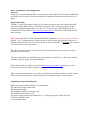
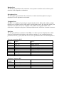
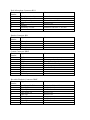
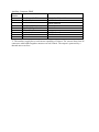
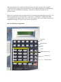
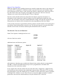
DRC1 Configuration Handbook to software Version 3.6
A.W. Communication Systems Ltd.
Crook Barn
The Crook
Roweltown, Carlisle
Cumbria CA6 6LH
England
Tel 44-(0)-1697-748777 Fax 44-(0)-1697 748778
www.toneremote.co.uk
Part 1, Installation and Configuration.
Forward
Thank you for purchasing the DRC-1 desktop radio control unit. If used within the guidelines
specified herein, the unit will provide trouble free operation without the need for service or
repair.
Repair Philosophy.
The DRC-1 has been designed using the very latest microprocessors and employs specially
written and tuned DSP software. Should the unit appear not to function properly, double
check the programming parameters you have set. It may also be worth checking the user
feedback file (if any) online at http://www.toneremote.com. This will aid fault identification
and correction.
Please note: The DRC-1 has no internal adjustments and there are no user repairs possible to
the unit. A.W. Communications employ special to type test jigs and diagnostic software to
calibrate and repair the units. Users who choose to open up the DRC-1 invalidate the warranty
issued when the unit was purchased.
We offer a range of service contracts for all of our product range, please contact our sales
department for full details.
The unit is sold under our standard terms and conditions and will carry a full twelve months
warranty subject to proper use and installatio n.
Please take the time to register your unit at http://www.toneremote.com and receive your
password to access the software support section of the web site.
When seeking technical support, you may be asked for the installed software version number.
Please see menu descriptions, which instruct how to read the software version number.
Unpacking and unit identification.
Within the carton (single Package) you should find:The main body of the control unit
The telephone handset.
The telephone handset connecting cord.
The modular power supply unit.
The power supply unit cord terminated in a 13 amp plug (fused at 5amp) UK only
Telephone interface cable
A line interface cable
Connectors on the rear panel.
Auxiliary Port
Power
Record / Playback Port
Comms
PTT
Headset Microphone Telephone Line (PW)
Telephone handset
On side of unit
Power Supply Port.
The unit requires 12vDC nominal supply, centre pin positive. It is recommended that only the
supplied power supply unit is employed.
Auxiliary Port.
The auxiliary port is used for connecting third party equipment such as modems, employed in
data capable radio systems.
Record And Playback Port.
The record and playback port is intended to be connected to incident recording devices such
as instant record / replay units installed at the dispatcher position. These units are often used
to record and playback as many times as required radio and telephone traffic to the dispatche r.
Communication (Comms) Port.
The comms port is used to read and program the unit from a lap top when in program mode,
and to provide a data connection between the A.W.C. touch screen system when it is
employed as the man machine interface. This port is also used to connect a selcall logging
printer.
PTT.
This connector facilitates the connection of a foot operated PTT switch.
Headset Port.
The headset port facilitates the connection of an operator’s headset used to achieve quiet
operation at the dispatcher workstation.
Microphone Port.
The microphone port facilitates the connection of a desk stand microphone as may be
employed in a taxi dispatcher work station.
Telephone Port.
The DRC-1 is capable of operating in common headset mode. This mode enables a single
headset to be switched between radio traffic and telephone traffic. By using this facility, the
dispatcher can make and receive telephone calls without missing radio traffic. This
connection is designed to plug into a desktop telephone unit, which has a headset connector.
Line Port.
The line port facilitates connection of the DRC-1 to either a private telephone line, which
connects the dispatch workstation to the radio base station, or any communication port
presented as 4 wire, 2 pair (send and receive). See specifications for levels and frequencies.
Line port connections RJ45
Pin
Signal
Number
1
Line in 0
2
Line in 1
3
Line Out 0
4
TX data +
5
TX data 6
Line Out 1
7
PTT O/p
8
Ground
Telephone Connector RJ8
Pin
Signal
Number
1
Send audio
2
Return audio
3
Return audio
4
Send audio
Notes
600Ω balanced
600Ω balanced
600Ω balanced
Used with DS32 switch
Used with DS32 switch
600Ω balanced
Active low
Notes
Desk Microphone Connector RJ11
Pin
Signal
Number
1
Telephone select I/p
2
Ground
3
Microphone I/p
4
PTT
5
Ground
6
Auxiliary +12vDC
Handset Connector RJ8
Pin
Signal
Number
1
Microphone 2
Ear 3
Ear +
4
Microphone +
Comms Connector DB9F
Pin
Signal
Number
1
N/C
2
TX data
3
RX data
4
DTR
5
Ground
6
DSR
7
N/C
8
N/C
9
TOSC I/p
Record & Playback Connector DB9F
Pin
Signal
Number
1
Auxiliary +12vDC
2
Tape O/p 0
3
Tape I/p 0
4
Tape Select I/p
5
Tape O/p
6
Ground
7
Tape O/p 1
8
Tape I/p 1
9
Ground
Notes
Active Low
Electret biased 10KΩ
Active Low
Limited to 500 mA ** see note
Notes
Notes
Data output from the unit
Data input to the unit
Data Terminal Ready
Data Set Ready
Active low
Notes
Limited to 500 mA ** see note
600Ω balanced
600Ω balanced
Active Low
Active Low
600Ω balanced
600Ω balanced
Auxiliary Connector DB9F
Pin
Signal
Number
1
Auxiliary +12vDC
2
Audio Out 0
3
Audio In 0
4
Auxiliary PTT
5
Ops Busy Signal/or Alarm
6
Ground
7
Audio Out 1
8
Audio In 1
9
Ground
Notes
Limited to 500 mA ** see note
600Ω balanced
600Ω balanced
Active Low
Active Low
600Ω balanced
600Ω balanced
** The auxiliary supply has a total current capability of 500mA. The current draw from all
connectors when added together must not exceed 500mA. The output is protected by a
thermal auto-reset fuse.
After unpacking the unit, connect the handset to the main body using the cable supplied.
Connect the power supply unit to the main body of the telephone and plug into an appropriate
supply. The unit will initialise and display a welcome message before going into its
operational state.
When in its operational state, the menu system is accessible and configuration may begin. The
menu is divided into two sections being 1, user menu, 2, installation / configuration menu.
The installation and engineer menu can be PIN code locked to prevent accidental alteration of
configuration settings. Ex factory these menus are unlocked
Keys Used During Configuration.
Scroll Up
Scroll Down
Menu
Clear
Alphanumeric keys
Volume Up
Volume Down
The Menu key has two functions. On first press it engages the menu system. Once in the
menu system, the menu key acts as carriage return to agree and select the values set in the
options field. Exiting the menu area causes the selected values to be stored.
The scroll up and down keys move through the menu options, and pressing menu selects the
desired option.
The clear key steps back one place in the selection process. For example, if tone set has been
selected, then operation of the clear key will step back one place to sellcall options.
The volume up and down keys are used when configuring audio related options.
Menu Structure.
User Menu
Installation Menu
(may be pin code protected)
Menus In Order Of Presentation
User Menu
Selcall Status
Set Radio Channel
Headset Volume
Handset Volume
Default speaker Vol
Keypad Beeps
Set Time
Set date
Display Contrast
Set Microphone Source
Lamp & Button test
Set Ident alpha tags
Set Status alpha tags
Set Channel alpha tag
Set Default Channel
F Key Channels
Software Version
Install Menu
Emulation Mode
Set Mic Gain
Selcall Tone set
Tone length
Selcall ident size
Selcall status size
Selcall codes
Sets the outgoing status in selcall signalling
Used in DS32 mode only
Range 0 to 99
Range 0 to 99
Range 0 to 99
Click-Pip-Off
Hrs – Mins
DD – MM – YY
Range 0 to 9
Internal – External
Reports on display buttons pressed
Input alpha tags on a per ident basis
Input alpha tags on a per status basis
Input alpha tag for channel
Sets the power- up channel
Used in M80 mode only
Reports presently installed software version number
Determines base station keying options
Use Vol UP/Down to set selected microphone gain.
Select tone set to be used
Set in mS the selcall tone length
Set number of digits (variable) in ident
Set number of digits (variable) in status
Sub menu for setting all selcall codes
Set Rx Call code
Set RX emergency code
Set RX ack to TX
Set RX ack to close down call
Set RX ack to interrogate
Set RX ack to locate
Set TX call code
Set TX code for interrogate
Set TX code for locate call
Set TX code for close down
Set TX code for ack to RX call
Set TX ack to night service
Ack timeout
Set how long system waits for ack
L.E.T.
Set link establishment time delay
Call Stack Option
Set how the call stack functions
Leading Rept tone
Set if leading repeat tone is on or off
Circulating Calls
Special Function used with Philips Voting Systems
Alert Tone Default Set if enabled at power up
Alert Tone Type
Intermittent or continuous tome
Call Printer
Turn logging printer on/off
RX Vox time
Set how long input vox hangs
Motorola Func.
Set the Motorola keying options
Talk through mode Set local (via DRC-1) or remote via Base Station
Night Service Lock Sets lock out time
Teleconnect Lock
Sets lock out time
Group Connect Timer Set how long group connects are established.
Line Proving
Sets line proving (TT holdoff) on/off
Background mute
Used when controlling switch in DRC32 mode
FAC Key
Set function of FAC key
Trim Line O/P
Trim line output level
Trim LineI/P
Trim line input level
Open Collector OP Set how pin 5 Aux connector is triggered
Password
Set Pin code and turn protection on
Engineering Adjustments.
Ex factory the DRC-1 will be set to system peak levels of –10dBm to line, and if selected, the
tone keying will be –18dB down on system peak or –28dBm.
The trim adjustments found in the installation menu permit adjustment of these levels over the
range of -2 to -22 dBm.
Setting the correct line levels can be achieved in one of two ways depending upon the type of
test equipment to hand. Method 1 requires an ordinary AC milivoltmeter calibrated in dBm
and terminated in 600Ω. Method two requires a selective tone measuring set with a bandwidth
of 100hz. Both require an audio oscillator.
Method 1.
In the installation menu set keying to DC.
In the installation menu set talk through to Local.
Connect an audio oscillator to the line input pins of the line port.
Connect the AC milivoltmeter to the Aux port audio output pins 2 & 7.
Set the audio oscillator to 1Khz –20dBm.
From the installation menu select trim line input
Adjust the line input for a reading of –20dBm on the meter
Store this value (press menu)
Increase the line input level to –10dBm and check output is also –10dBm
Increase the input level to 0dBm and check output remains at –10dBm +2dBm-0
Transfer the meter to the line output port and set input level to –20dBm
Select trim output level and set level on meter for –20dBm, store this value.
Increase line input level to 0dBm and check output level remains at –10dBm +2dBm-0.
Theory
Limiting within the DRC1 amplifier chain is set to start at around –10dBm. The initial setting
process at –20dBm is undertaken at a level which will be well outside of the limiting range.
By setting the initial level on the auxiliary ports, the input gains are set to a known value, and,
out of limiting. The output is then set against this known value.
Method 2.
From the installation menu set keying to 2970Hz, store this value (press menu).
From the installation menu set talk through to local
Connect the selective measuring set to the line output pins on the line port.
Set the measuring set to 2970Hz and a bandwidth of not more than 100Hz
From the installation menu select trim line output level
Whilst pressing the PTT key adjust the line output level for –28dBm as seen on the selective
measuring set. Store this value (press menu).
Place an audio oscillator onto the line input pins of the line port
Set the oscillator for 1Khz –20dBm
Set the selective measuring set to 1Khz 100Hz band width.
Press talk through (led on)
From the installation menu select trim line input
Adjust the trim until the output is –20dBm. Store value (press menu).
Increase the line input level from the oscillator by 10dB
Check that a corresponding increase is seen on the selective measuring set.
Increase the line input to 0dBm, and check output is –10dBm +2dBm-0.
Theory. The key tone level has a fixed ratio to peak level of –18dB or –28dBm. By setting
the line output level whilst measuring the key tone the line output amplifiers are calibrated
and the gain values stored. Setting the input to –10dBm and adjusting the input amps for –
10dBm as seen on the output calibrates the internal system gain to 0dB. The base station
installation should be adjusted for nominal –10dBm levels, however using the DRC-1 line
trim facility permits local adjustments of the full path loop gain.
The Installation Menu in detail
Emulation Mode
The emulation mode provides the system programmer with the base station keying options.
The DRC-1 has embedded software for Simoco and Motorola keying plus Dc keying. The
options in order:DRC-1 Hardwire PTT. The DRC-1 will use its open collector transistor to pull down the base
stations PTT line.
DRC-1 2970Hz. The DRC-1 will output 2970Hz to line when any PTT key is operated.
DRC Switch interface. Used when controlling a DS32 radio switch.
M80 Remote. Emulates an M80 terminal in remote mode. The keytone will be 2970Hz.
M80 Local. Emulates an M80 terminal in local mode.
MTRLA 2100. Using 2100Hz to key a Motorola base station.
MTRLA 2175. As above using 2175Hz.
MTRLA 2325. As above using 2325Hz. ** A complete description of Motorola tone
signalling is given later in the document.
Set Microphone gain.
Using this facility the individual amplifiers associated with handset, headset, and internal
microphone (located in the lower part of the case) can be adjusted. The menu option [Select
Mic Source] determines if the headset or internal microphone is adjusted within this facility.
The handset is always available.
From the menu select [installation] and [set mic gain]. From this point pressing the transmit
key on the main keypad will bring into service either the internal microphone or the headset
microphone depending upon the menu item [Select Mic Source]. Use the volume up/down
keys to increase / decrease gain. The output may be measured either at the line port or judged
by ear from the base station. The purpose is to achieve an approximately equal output from
headset/internal microphones and the handset microphone. Whilst in this mode picking up the
handset and pressing its PTT enables adjustment of the handset microphone.
Selcall Tone Set.
Press [menu] to select this item. Using the scroll up/down keys, select the desired tone set
from the list. Press [menu] to store your selection and then press [clear] twice to exit the menu
facility and implement the changes. The display should indicate that changes are being
implemented.
Selcall Tone Length
Press [menu] to select this item, use the scroll up/down keys to move through the options.
Press [menu] to select desired option and then press [clear] twice to exit the menu system and
implement the changes. Please note that pressing clear once will allow you to remain in the
menu facility to continue configuration. All items selected and altered will be implemented
upon exit from the menu system.
Selcall Ident Size.
This item permits the selection of how many digits are used for ident purposes. This value is
independent to the fixed digits one may use within the selective calling architecture. Press
[menu] to access this item, then use the scroll up/down keys to select the desired number,
press [menu] to select your choice. Press [clear] twice to exit and store the selection.
Selcall Status Size.
This item permits the selection of how many digits are used for status reporting. Press [menu]
to select this item and use the scroll up/down keys to make selection. Press [menu] to store
selection then press [clear] twice to exit the menu facility and store the selection. Note the
option “No status” is available.
Selcall Codes.
This menu item is a gateway to a sub menu where all of the selective calling codes are set.
Press [menu] to acquire the sub menu, then use the scroll up/down keys to move through the
sub menu items.
Selcall ACK time Out.
This item sets how long the DRC-1 waits for an ack from a called mobile or portable. Press
[menu] to access this item, then use the scroll up/down keys to move through the options, use
[menu] to select the desired option, and then press [clear] twice to exit the menu item and
implement the selection.
Link Establishment Time (LET).
The LET is the time delay placed between the call key being pressed and the selective calling
tones being placed onto the line. The purpose of the LET is to allow the base station transmit
signal to rise, and the receiver mute of the target mobile to open before the selective calling
tones are sent. Sending the tones prematurely will result in some of the digits being missed by
the mobile and the call failing. Press [menu] to select this item, then, as per the on screen
advice input three digits, which are multiples of 10mS. The total LET time is the number
entered multiplied by 10mS, e.g. 40 would result in an LET of 400mS. Having entered the
digits press [clear] twice to exit and implement the change.
Call stack Options.
The DRC-1 offers a call stack to store incoming idents. This menu facilitates how the calls are
handled within the DRC-1. Select [menu] to access the menu item, then, use the scroll
up/down to move through the options. When the desired option is opposite the chevron,
pressing [menu] will select the option, then, press [clear] twice to store and exit the menu
facility. The options are:Call Stack Disabled. There is no call stack in use, and the received idents/status will
be displayed as they are received. The idents then will appear to go into a queue as if
the call stack is available, but this queue is only one call deep. Also, reception of
further idents will replace the ident waiting. To recall the ident from the one deep
queue, use the arrow keys as normal.
Discard Oldest Call. The call stack length is sixteen calls. When the call stack is full,
selecting this option will remove the oldest call from the stack and replace it with the
one currently being decoded.
Refuse Call If Full. The call stack length is sixteen calls. When the call stack is full no
further calls will be placed into the stack. ** also see logging printer. All these items
are programmed in the same way, press [menu] to select call stack options, use the
up/down scroll keys until the desired item is opposite the chevron, then press [menu]
to select item, then [clear] twice to store selection and exit the menu system.
Leading Repeat Tone
A leading repeat tone is sometimes used to signal to other DRC units that this call is outgoing
and not incoming when the DRCs are connected to a common line. The available options are
on/off. Select [menu] to access this item then use the scroll up/down keys to see the selection
available. Press [menu] to select the desired option, then, press [clear] twice to exit the menu
system and implement the changes.
Circulating Calls.
This is a special signalling method used only with Simoco / Philips voting systems.
Alert Tone Default
Sets if alert tones are enabled after power up / reset.
Alert Tone Type
Sets intermittent or continuous tones for alert status.
Call Log Printer.
All selcall activity can be routed to the communications connector for connection to a logging
printer. This menu item permits the logging output to be switched on and off. It should be
noted that if this output is enabled, and the call stack is full, the logging output will continue
and thus provide a record of all calls received when the stack is full. Press [menu] to access
this item, then use the up/down scroll keys to indicate on or off. Press [menu] to make
selection, and press [clear] twice to store end exit.
RX Vox Defeat Time
The line input to the DRC1 has a Voice Operated Switch (VOX), which removes from the
audio path constant line noise appearing on the line below the VOX level. The VOX switch is
defeated on incoming calls which produce audio above the VOX level, but if the vox where to
snap shut, pauses in speech may result in a fragmented message being heard. The defeat time
parameter sets how long the VOX hangs open after the incoming level drops below the VOX
threshold. The options are VOX off or delays in 2-second increments. Select [menu] to access
this item then use the scroll up/down keys to see the selection available. Press [menu] to
select the desired option, then, press [clear] twice to exit the menu system and implement the
changes.
MTRLA Function Keys.
This option permits the user to program the DRC-1 function keys to send Motorola signalling
functions to a Motorola base station. An explanation of the commonly used functions is given
later in this document. The options in order are:F1 to F4 function key set. Sets which Motorola function tone is allocated to the F1 to
F4 function keys.
Shift F1 to Shift F4 function key set Sets which Motorola function tone is allocated to
the Shift F1 to F4 function keys.
Talk through On tone Sets which tone is used to put TT on.
Talk through off tone. Sets which tone is used to switch off TT.
Squelch (mute) On tone. Sets which tone is used to mute the RX
Squelch (mute) off tone. Sets which tone will un- mute the RX.
Channels 1 to 4 setting tones. Sets which tones are used to select channels 1 to 4.
Channels 1 to 4 PTT tones. Allocates PTT tones to channels 1 to 4
Each of the above functions can also have a text message associated with it. In this way, the
operation of a function key to say change channel, will also output to the DRC-1 display
“ChN” to indicate the channel number switched to.
Press [menu] to select the MTRLA function menu, then use the scroll up/down to set the
desired item against the chevron. Press [menu] to select the item and two further choices now
exist.. Pressing the [zero] key will allow the programmer to scroll up and down the tone
frequency list to select which tone frequency is to be allocated to the function key in question.
Having placed the desired frequency against the chevron, press [menu] to store this value.
Now press the [1] key to enable a text message to be allocated to the function key. Using the
alpha-numeric keypad, each press will scroll through the alphabetical characters and numbers,
in a similar way as an SMS message is sent on your cell phone. Up to eight characters may be
entered. Press [menu] to store the entered text, then, press [clear] twice to exit the menu
facility.
Talk Through Mode
This parameter sets how talk through is achieved. The options are local or remote. In local
mode the audio for the transmitter is derived from that received by the DRC1 on its input line.
When the TT key is selected, the DRC1 will operate the PTT signal when the incoming VOX
is triggered, and also outputs to line the received audio. In remote TT mode, the base station
has to be configured to provide the talk through path, and talk through is enabled by an FSK
supervisory message to the remote site (Simoco) or Tone burst (Motorola).
Press [menu] to select this menu, then use the scroll up/down keys until the desired value is
against the chevron. Press [menu] to select then [clear] twice to store and exit.
Night Service Lockout, (timeout)
This menu item sets how long the TT path remains open when triggered by the night service
facility. Press [menu] to select this item, then using the numeric keys set the number of
seconds. Press [menu] to store your entry then [clear] twice to exit the menu system. Entering
00 renders the timer ineffective.
Teleconnect Lockout, (timeout)
This items determines how long the telephone to radio connect will remain linked. This will
automatically disconnect a teleradio link when the timer elapses. Press [menu] to access, then
using the numeric keys enter the number of seconds for the timer. Press [menu] to store your
entry, then [clear] twice to exit the menu facility. Entering 00 renders the timer ineffective.
Group Connect Timer
Timer used to automatically cancel group connects.
Line Proving Signal.
In both Simoco and Motorola line signalling, the controller can be set to send a tone or FSK
data burst to the remote site when the system is idling. The period of repetition is about one
per minute. This menu item permits the programmer to switch line proving on or off. In some
systems, failure to receive the line proving tone will cause the remote base station to go into
TT mode (line fail talk through). Press [menu] to select this item, then use the scroll up/down
to indicate on or off. Press [menu] to make your selection, then press [clear] twice to store and
exit the menu system.
Background Mute.
This function is used when the DRC is controlling a switch (either DRC32 or micro). The
function changes the way audio from the switch is monitored.
When “SET” an operator will hear audio from all the channels in his elected group until a
channel is selected. Once a channel is selected, only the audio from that channel will be heard
by the operator.
When “Cleared” the operator will hear audio from all the channels in the elected group and a
12dB increase will occur on selected channels.
In either state, selective calling will continue to operate normally.
Installer Password
This item sets the PIN code lock to prevent unauthorised access to the installation menu. 4
digits may be set. Press [menu] to access this item. Password is set to NONE by default, enter
4 digits then press [menu] to store the selection, then [clear] twice to exit the menu system
and implement the changes.
Selective Calling System.
The DRC1 has been equipped with a very flexible selective calling system. The number of
digits, digit purpose, and digit position within a string can all be configured. The menu system
provides prompts as the system is programmed, but within the limitation of the two line LCD
display.
Turning the Status facility on or off affects the rest of the selective calling process. The
number of status digits programmed in that step is checked by the system and an error
message issued if the quantity disagree. For example, if status is turned off, and the
programmer then enters status digits in the code field, the system will inform the programmer
“status digits bad”.
In essence, the code field can consist of variable digits, fixed digits, and status digits. The
system uses numbers for fixed digits, the # symbol for variable ident digits, and the * symbol
for variable status digits. The position of the # and * within the string determines where the
DRC1 expects to find the ident and status numbers
Here are a few examples:In a system requiring 99 idents and no status signalling, the programmer will decide to fix the
first 3 digits in a five-digit system. The fixed digits provide a filter when the radio frequency
is shared with other users. By entering 123## in the RX code field the programmer has set
123 as fixed digits, and the DRC1 will not decode any number not prefixed in this way. The
## digits are variable and indicate the mobile identity.
In the above system to add a status digit but keep the overall number of digits at 5, then the
fixed number would be reduced by one place, and a status digit added, thus.
12##*, or leading status *12##.
The relationship between the total number of digits, and the position within the string of the *
and # symbols holds true for all of the selective calling programming, and so no further
individual examples are given .
The Menu Items For Selective Calling
In the install menu, items [Selective Calling Ident Size], and [Selective Calling Status Size]
determine how many digits the DRC1 expects for these functions, not including any fixed
digits you may use. These options do not limit the overall number of digits used in the total
string.
From the user menu select RX call
Enter in the desired order, numbers for the fixed digits, # symbols for the ident variable digits
and * symbols for the status variable digits. The order they are entered represents where in the
incoming string the DRC1 will extract ident and status information, and the sequence must
match that set in the mobile radio sets.
Emergency Call
Sets the code DRC1 expects from a mobile resource signalling for urgent attention.
RX Ack to TX call
This parameter determines what the DRC1expects to receive in response to a TX call to a
mobile resource. If a code is set here, then the DRC1 will display “calling” and “connected”
as the call goes out and the Ack comes back. If the Ack is not received, then the DRC1 will
display “No Answer”. If a code is not set into this parameter, then the DRC1 will
automatically display “Connected” when the call goes out even if the mobile called is not
responding.
RX Ack To Close
In systems where it is desired to re- mute the mobile after a conversation with control, the TX
code “TX-Close” is programmed with a suitable code. If an Ack to the close message is
required, it is programmed into this parameter.
RX Ack To Interrogate
In some systems the mobile may be interrogated for a currently set status. This interrogation
normally doe’s not require any intervention from the mobile operative, and the interrogation
call goes un- noticed by the mobile crew. The response to the interrogation call is set in this
parameter, and must contain one or more * symbols if the status is required.
RX Ack To Locate
It is possible to interrogate a mobile for its position. The position can be set as part of the
status field in simple systems, or be a GPS data string in more modern systems. The
parameter set here is the sell call response to the locate call. If status information is intended
to carry the location, then the parameter set here must contain one or more * symbols to send
status information. If the location fix is a GPS data burst, then the mobile should have a
suitable protocol embedded to provide the correct sequence.
TX Call
This parameter sets the normal call emanating from control under operator control. Like the
RX code fields, it is possible to mix identity digits with an outgoing status instruction. The #
and * symbols represent the position within the string of ident and status digits respectively.
Where fixed digits are also required, the correct values will be entered into the desired string
location. For example, 12##** would send the numbers 12 with every call, and the operator
entered digits in the ##** positions. It should be noted that the pattern of digits must
correspond with the field sizes set up in the string length sections of memory programming
listed above.
TX Close.
The code set here causes the mobile radio set to re- mute after a conversation with control.
This code is transmitted in response to the “close” button on the DRC1 keypad being
operated.
TX Ack To RX.
When a mobile calls in and that call is queued for operator attention at some later time, the
mobile benefits by having a confirmation signal that the call has actually been received and
queued. The code set into this parameter achieves this, and the mobile radio set should be
programmed to give a suitable response when this code is received.
TX Night Ack To RX
In some systems the control room will not be manned 24 hours a day. The DRC1 has been
designed to provide a “Night Service”, and this mode is engaged by operating the night key
on the DRC1 keypad. In night service, talk through is engaged permanently and calls are not
queued.
It is intended that the mobiles will communicate with each other when night service is
enabled. The parameter set here is intended to enable mobile to mobile calls under sell call
control. For example if the code AAAAA were entered, then upon receiving a valid incoming
selcall, the DRC1 would output AAAAA. This would open all mobiles for communication.
Selcall General Information.
Whilst any selcall codes are being set within the installation menu facility, it should be noted
that the keys F1-F4 provide codes A to D and, Shift-0 for Null (no tone) respectively.
Outgoing Status Code
The DRC-1 if configured, will send an outgoing status as part of the normal selcall facility.
Should the operator need to change the code sent, then operation of the
Shift-2 key will access a menu to achieve this change. [Shift-2], [0 to 9], [menu] are the four
key strokes needed to change your outgoing status code.
Night Service.
The night service facility is turned on and off by the operator using the Night key on the
DRC-1. When the night service is enabled, the reception of any valid sel call code will enable
the talk through path, and cause the system to output an all- call sel call code. If programmed,
the night service lock out will remove the TT facility when the time programmed into this
parameter time out.
Audio Recording and Playback
A local audio recording device may be connected to the record and playback port. Incoming
and outgoing audio is continuously streamed to this port for recording. Should the recording
device be capable of playback, then operating the DRC-1 [Aux] key will open the audio input
channel within the DRC-1. The playback audio may then be listened to in the DRC-1
loudspeaker and headset.
Display Backlight
The display backlight may be turned on and off by using [Shift-3]
Selcall Alerts
An audible alert tone is heard in the DRC-1 loudspeaker and headset each time a selcall code
is decoded. This alert tone may be turned on and off by use of the [Alert] key.
Changing Radio Channel
The DRC-1 if configured, will provide multi-channel operation. The method of achieving
multi-channel may be simply switching channels on a single base station, or combining
several base stations into a common line link. In any case, the DRC-1 will permit the operator
to switch channel of operation by use of the [Shift-1] key. In Simoco based systems this is
likely to result in an FSK data message being sent to site, and in Motorola systems a change
in guard tone frequency will take place within the DRC-1. [Shift-1], [1 to 4], [menu] are the
four key strokes required to change channel.
Motorola Tone Signalling.
Within the Motorola tone signalling format, the controller sends three tones to the remote site
every time PTT is operated or a function switch is operated. The tones are basically a high
level guard tone (used to alert or wake up the base station) a function tone, and a lower level
key tone which is the same frequency as the high level guard tone. The low level tone
continues to be sent for the period that the PTT key is operated.
The base station installer will need to determine the function required, the button it is
allocated to on the control unit, and the frequency used for that function within the radio
system. The chart below shows the common Motorola settings. Note that the signal tone will
only perform one function, this is determined by the programming of the base station.
A line proving tone may be generated by the base station, and will consist of one of the guard
tone options, again determined at system set up. The line proving tone is present all the time
until the receiver mute on the base station opens and then the tone is removed.
The Motorola Tone set and Functions
Guard Tone Options- both high and low level.
2100Hz
2175Hz
2325Hz
850Hz
Ack tone from base station
Additional tones and function options
Frequency
2050Hz
1950Hz
1850Hz
1750Hz
1650Hz
1550Hz
1450Hz
1350Hz
1250Hz
1150Hz
1050Hz
OptionA
CTCSS toggle
#1 function
#2 function
RX 2
RX 2
Max Squelch
Min Squelch
#3 Function
#4 Function
Option B
Option C
Mute
Mute
TT off
TT On
CTCSS 1 select
CTCSS 2 select
CTCSS 3 select
CTCSS 4 select
Channel 1
Channel 2
Channel 3
Channel 4
CTCSS On
CTCSS Off
Wild Card 1 On
Wild Card 1 Off
Wild card 2 On
Wild card 2 Off
All of the above functions are set within the Motorola base station when it is programmed.
The DRC-1 function and Shift-function keys can be programmed to send these tone
frequencies to the remote base station.
In any signal sent to the base station, the tone must have three components. A high and low
level guard tone plus a function tone sandwiched between them. When the PTT is operated,
the system must re-write the channel in use. If 2100Hz is used a guard tone, then for example,
2100 high-1950-2100low are sent. The 1950 sets or resets the station to channel 1 and the
guard tones wake the base station and keep it keyed whilst the PTT is held on.
Hints and Tips
Using filter Digits In Selcall.
Where the DRC-1 is deployed on commercial (shared) radio frequencies, it is advisable to use
fixed digits as part of the selcall string. The fixed digits act as a filter for the decoding system.
For example, if the selcall pattern within the DRC-1 is set to ###**, then the DRC-1 will
decode any five digit string which is received as 3 digits of ID plus two status digits. If the
selcall string is set to 8##**, then, only strings which begin with an 8 will be decoded.
Be Organised
Use the planning sheet found at the end of this document to plan and document your
configuration settings.
230507/awc/drc-config3
Compliance.
What Is RoHS ?
The RoHS Directive stands for "the restriction of the use of certain hazardous
substances in electrical and electronic equipment". This Directive bans the placing
on the EU market of new electrical and electronic equipment containing more than
agreed levels of lead, cadmium, mercury, hexavalent chromium, polybrominated
biphenyl (PBB) and polybrominated diphenyl ether (PBDE) flame retardants.
Manufacturers need to understand the requirements of the RoHS Directive to
ensure that their products, and their components, comply.
The RoHS Directive and the UK RoHS regulations came into force on 1 July 2006.
The RoHS Directive is an Article 95 single market directive.
AWCSL hereby declare that all of our product range complies in full with the
RoHS directive
Menu Item
Emulation Mode
Set Mic Gains
Selcall Tone Set
Selcall Tone Length
Selcall Ident size
Selcall Staus Size
Selcall Codes
Value Set and or alpha tag
RX call
RX emergency call
RX ack to TX call
RX ack to Close
RX ack to Interrogate
RX ack to locate
TX call
TX interrogate
TX locate
TX close
TX ack to RX call
TX night ack to RX
Selcall ack timeout
Link Establishment
Call Stack Option
Leading repeat tone
Circulating calls
Alert tone default
Alert tone type
Call Log printer
RX vox defeat
Motorola functions
Talk through mode
Night Service Lockout
Teleconnect Lockout
Group connect timer
Line Proving
Back Ground Mute
FAC key
Trim Line O/P
Trim Line I/P
Open Collector
F1 key function
F2 key function
F3 key function
F4 key function
Shit-F1 function
Shift-F2 function
Shift-F3 function
Shift-F4 function
TT on tone
TT off tone
Squelch on tone
Squelch off tone
Channel 1 tone
Channel 2 tone
Channel 3 tone
Channel 4 tone
Channel 1 TX tone
Cahnnel 2 TX tone
Channel 4 TX tone