1
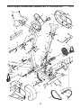
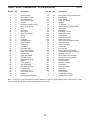
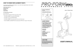
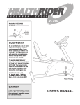
aa
®
Model No. PFEVEX34181
Serial No.
Class H C Fitness Product
Write the serial number in the
space above for future reference.
aa
Serial
Number
Decal
QUESTIONS?
As a manufacturer, we are committed to providing complete
customer satisfaction. If you
have questions, or if there are
missing or damaged parts, we
will guarantee complete satisfaction through our Customer
Service Department.
Please CALL:
0345-089009
Or WRITE:
ICON Fitness Lifestyle Ltd.
Greenwich House
223 North Street
Sheepscar
West Yorkshire
Leeds LS7 2AA
CAUTION
Read all precautions and instructions in this manual before using
this equipment. Keep this manual
for future reference.
USER'S MANUAL
®
TABLE OF CONTENTS
IMPORTANT PRECAUTIONS . . . . . . . . . . . . . . . . . . . . . . . . . . . . . . . . . . . . . . . . . . . . . . . . . . . . . . . . . . . . . . . .3
BEFORE YOU BEGIN . . . . . . . . . . . . . . . . . . . . . . . . . . . . . . . . . . . . . . . . . . . . . . . . . . . . . . . . . . . . . . . . . . . . . .4
ASSEMBLY . . . . . . . . . . . . . . . . . . . . . . . . . . . . . . . . . . . . . . . . . . . . . . . . . . . . . . . . . . . . . . . . . . . . . . . . . . . . . . .5
HOW TO USE THE PROFORM® 890E . . . . . . . . . . . . . . . . . . . . . . . . . . . . . . . . . . . . . . . . . . . . . . . . . . . . . . . . .8
HOW TO USE THE HAND PULSE MONITOR . . . . . . . . . . . . . . . . . . . . . . . . . . . . . . . . . . . . . . . . . . . . . . . . . . .10
MAINTENANCE AND TROUBLE-SHOOTING . . . . . . . . . . . . . . . . . . . . . . . . . . . . . . . . . . . . . . . . . . . . . . . . . . .11
CONDITIONING GUIDELINES . . . . . . . . . . . . . . . . . . . . . . . . . . . . . . . . . . . . . . . . . . . . . . . . . . . . . . . . . . . . . . .13
PART LIST . . . . . . . . . . . . . . . . . . . . . . . . . . . . . . . . . . . . . . . . . . . . . . . . . . . . . . . . . . . . . . . . . . . . . . . . . . . . . .14
EXPLODED DRAWING . . . . . . . . . . . . . . . . . . . . . . . . . . . . . . . . . . . . . . . . . . . . . . . . . . . . . . . . . . . . . . . . . . . .15
HOW TO ORDER REPLACEMENT PARTS . . . . . . . . . . . . . . . . . . . . . . . . . . . . . . . . . . . . . . . . . . . . .Back Cover
2
EXPLODED DRAWING—Model No. PFEVEX34181
R1298A
47
5
23
35
6
61
55
8
49
35
35
18
17
7
59
7
19
59
56
43
56
9
64
63
38
64
61
35
61
55
45
22
55
21
35
10
38
55 61
26
11
33
46
25
56
44
26
41
46
3
35
36
44
30
65
34
27
25
22
50
65
4
44
54
34
35
48
41
57
20
60
46
39
58
14
15
12
40
24
44
13
53
46
44
52
62
32
16
51
54
66
2
15
29
36 42
67
31
36
66
68
35
1
49
15
28
PART LIST—Model No. PFEVEX34181
Key No. Qty.
1
2
3
4
5
6
7
8
9
10
11
12
13
14
15
16
17
18
19
20
21
22
23
24
25
26
27
28
29
30
31
32
33
34
1
3
1
1
1
1
4
1
1
1
1
1
1
1
2
1
2
1
1
1
1
1
1
1
2
2
1
1
1
1
1
1
1
1
Description
Key No. Qty.
49” Drive Belt
M4 x 38mm Screw
Seat Knob w/Pin
Reed Switch w/Wire
Console
Resistance Knob w/Cable
M4 x 16mm Screw
Seat
Seat Post
Seat Collar
Seat Tube Spacer
Spring
Frame
Flywheel
Round Endcap
Rear Stabiliser
Foam Grip
Handlebar
Handlebar Post
Left Pedal w/Strap
Right Pedal w/Strap
Crank/Pulley
Right Side Shield
Left Side Shield
Adjustable Endcap
Wheel
Front Stabiliser
Idler Wheel Bolt
Idler Wheel Bracket
Flywheel Axle
Flywheel Cover
M4 x 25mm Screw
Magnet
Crank Bearing Assembly
35
36
37
38
39
40
41
42
43
44
45
46
47
48
49
50
51
52
53
54
55
56
57
58
59
60
61
62
63
64
65
#
#
#
13
2
1
2
2
1
2
2
2
8
1
3
2
1
2
1
1
1
2
4
7
5
1
1
3
4
7
1
1
2
2
1
1
1
R1298A
Description
M4 x 16mm Washer Head Screw
608 Bearing
Cable Clamp
Pulse Grip Screw
M6 Nut
“C” Magnet
M10 x 45mm Button Head Bolt
Idler Pulley
Pulse Wire
M10 Nylon Locknut
Right Pedal Strap
M10 Washer
Handlebar Endcap
Reed Switch Clip
M6 x 16mm Self-tapping Screw
Left Pedal Strap
Resistance Hook
Clamp Nut
Hex Jam Nut
M10 x 75mm Carriage Bolt
M10 x 22mm Button Head Bolt
M8 Nylon Locknut
M8 x 43mm Hex Head Bolt
M6 x 64mm Hex Head Bolt
M8 Lock Washer
#8 Flat Washer
M10 Lock Washer
Clamp Bolt
Pulse Handlebar
Pulse Grip
M8 Axle Nut
User’s Manual
Caution Decal Sheet
Warning Decal Sheet
Note: “#” indicates a non-illustrated part. Specifications are subject to change without notice. See the back cover
of this manual for information about ordering replacement parts.
14
IMPORTANT PRECAUTIONS
WARNING: To reduce the risk of serious injury, read the following important precautions before
using the PROFORM® 890E exercise cycle.
1. Read all instructions in this manual before
using the exercise cycle. Use the exercise
cycle only as described.
9. Always keep your back straight when using
the exercise cycle. Do not arch your back.
10. If you feel pain or dizziness at any time
whilst exercising, stop immediately and
begin cooling down.
2. It is the responsibility of the owner to ensure
that all users of the exercise cycle are adequately informed of all precautions.
11. The exercise cycle is intended for in-home
use only. Do not use the exercise cycle in a
commercial, rental or institutional setting.
3. Use the exercise cycle indoors, away from
moisture and dust. Place the exercise cycle
on a level surface, with a mat beneath it to
protect the floor or carpet from damage.
12. The decal shown below has been placed on
the exercise cycle. If the decal is missing, or
if it is not legible, please call our Customer
Service Department at 0345-089009 to order
a free replacement decal. Apply the decal in
the location shown.
4. Inspect and tighten all parts regularly.
Replace any worn parts immediately.
5. Keep children under the age of 12 and pets
away from the exercise cycle at all times.
6. The exercise cycle should not be used by
persons weighing more than 250 pounds.
7. Wear appropriate clothing when exercising;
do not wear loose clothing that could become
caught on the exercise cycle. Always wear
athletic shoes for foot protection.
8. The pulse monitor is not a medical device.
Various factors, including the user's movement, may affect the accuracy of heart rate
readings. The pulse monitor is intended only
as an exercise aid in determining heart rate
trends in general.
WARNING: Before beginning this or any exercise program, consult your physician. This is especially important for persons over the age of 35 or persons with pre-existing health problems. Read
all instructions before using. ICON assumes no responsibility for personal injury or property damage sustained by or through the use of this product.
3
a
BEFORE YOU BEGIN
Thank you for selecting the innovative PROFORM®
890E exercise cycle. Cycling is one of the most popular and effective exercises for improving cardiovascular fitness and toning the body. The PROFORM® 890E
blends advanced engineering with contemporary
styling to let you enjoy the benefits of this exercise in
the convenience and privacy of your home.
tions, please call our Customer Service Department at
0345-089009. To help us assist you, please mention
the product model number and serial number when
calling. The model number is PFEVEX34181. The serial number can be found on a decal attached to the
PROFORM® 890E (see the front cover of this manual
for the location of the decal).
Please read this manual carefully before you use
the PROFORM® 890E. If you have additional ques-
Before reading further, please familiarise yourself with
the parts that are labelled in the drawing below.
Console
Handlebars
Pulse Monitor
Resistance Knob
Seat
FRONT
Seat Post
Seat Knob
a
Pedal
Front Wheels
Side Shield
Adjustable Endcap
BACK
RIGHT SIDE
4
CONDITIONING GUIDELINES
For maximum fat burning, adjust the intensity of your
exercise until your heart rate is near the middle number in your training zone as you exercise.
The following guidelines will help you to plan your
exercise program. Remember that proper nutrition
and adequate rest are essential for successful results.
Aerobic Exercise
WARNING: Before beginning any exercise
program, consult your physician. This is especially important for persons over the age of 35
or persons with pre-existing health problems.
If your goal is to strengthen your cardiovascular system, your exercise must be “aerobic.” Aerobic exercise is activity that requires large amounts of oxygen
for prolonged periods of time. This increases the
demand on the heart to pump blood to the muscles,
and on the lungs to oxygenate the blood. For aerobic
exercise, adjust the intensity of your exercise until
your heart rate is near the highest number in your
training zone.
EXERCISE INTENSITY
Whether your goal is to burn fat or to strengthen your
cardiovascular system, the key to achieving the
desired results is to exercise with the proper intensity.
The proper intensity level can be found by using your
heart rate as a guide. The chart below shows recommended heart rates for fat burning, maximum fat burning, and cardiovascular (aerobic) exercise.
WORKOUT GUIDELINES
Each workout should include three important parts: a
warm-up, training zone exercise, and a cool-down.
Warming up—Begin each workout with 5 to 10 minutes of stretching and light exercise. A proper warmup increases your body temperature, heart rate and
circulation in preparation for exercise.
AGE
b.p.m.
Training zone exercise—After warming up, increase
the intensity of your exercise until your heart rate is in
your training zone for 20 to 30 minutes. (During the
first few weeks of your exercise program, do not keep
your heart rate in your training zone for longer than 20
minutes.)
AEROBIC
MAX. FAT
FAT BURN
To find the proper heart rate for you, first find your age
at the top of the chart (ages are rounded off to the
nearest ten years). Next, find the three numbers
below your age. The three numbers are your “training
zone.” The lowest number is the recommended heart
rate for fat burning; the middle number is the heart
rate for maximum fat burning; and the highest
number is the heart rate for aerobic exercise.
Cooling down—Finish each workout with 5 to 10
minutes of stretching. This will increase your flexibility
and will help to prevent post-exercise problems.
EXERCISE FREQUENCY
To maintain or improve your condition, plan three workouts each week, with at least one day of rest between
workouts. After a few months of regular exercise, you
may complete up to five workouts each week if
desired. Remember, the key to success is make exercise a regular and enjoyable part of your everyday life.
Burning Fat
To burn fat effectively, you must exercise at a relatively low intensity level for a sustained period of time.
During the first few minutes of exercise, your body
uses easily accessible carbohydrate calories for energy. Only after the first few minutes of exercise does
your body begin to use stored fat calories for energy.
If your goal is to burn fat, adjust the intensity of your
exercise until your heart rate is near the lowest number in your training zone as you exercise.
CAUTION: Be sure to progress at your own pace
and avoid overdoing it. Incorrect or excessive training may result in injury to your health.
13
HOW TO ADJUST THE REED SWITCH
HOW TO ADJUST THE DRIVE BELT
If the console does not display correct feedback, the
reed switch should be adjusted. To adjust the reed
switch, the Left Side Shield (24) and the Flywheel
Cover (31) must be removed. Using an adjustable
wrench, turn the Left Pedal (20) clockwise and
remove it. Next, remove the indicated Screws (2, 32,
35, 49). Turn the left arm of the Crank (22) to the
position shown and slide off the Left Side Shield and
the Flywheel Cover.
The exercise cycle features a Drive Belt (1) that must
be kept properly adjusted. If the Drive Belt slips as you
pedal, it should be adjusted. To do this, the left side
shield and the flywheel cover must be removed. Refer
to the instructions at the left and remove these parts.
1
44
24
22
20
1
32
31
44
2
35
Locate the Drive Belt (1). To tighten the Drive Belt,
loosen the bottom M10 Nylon Locknut (44) and then
tighten the upper M10 Nylon Locknut (44) slightly; be
careful not to overtighten the Drive Belt. When the
Drive Belt is properly adjusted, tighten the lower M10
Nylon Locknut (44). Then, reattach the left side shield,
the flywheel cover, and the left pedal.
49
Next, locate the Reed Switch (4). Turn the arms of the
Crank (22) until the Magnet (33) is aligned with the
Reed Switch. Loosen but do not remove the indicated
Screw (35). Slide the Reed Switch slightly closer to or
away from the Magnet. Retighten the Screw. Turn the
Crank for a moment. Repeat until the console displays
correct feedback. When the Reed Switch is correctly
adjusted, reattach the left side shield, flywheel cover
and left pedal.
35
33
4
22
12
ASSEMBLY
Place all parts of the exercise cycle in a cleared area and remove the packing materials. Do not dispose of the
packing materials until assembly is completed.
Assembly requires the included allen wrench
spanners
.
, a phillips screwdriver
1. Hold the Handlebar Post (19) near the Frame (13)
as shown. Feed the Resistance Cable (6) and the
Reed Switch Wire (4) into the Frame, and then slide
the Handlebar Post into the Frame. Be careful not
to pinch the Resistance Cable or the Reed
Switch Wire. Attach the Handlebar Post with three
M10 x 22mm Button Head Bolts (55) and three M10
Lock Washers (61).
and two adjustable
1
5
The Console (5) requires one 9V battery (not included). An alkaline battery is recommended. Refer to
the inset drawing. Locate the battery door on the
back of the Console. Slide the battery door to the left
and open it as shown. Press a battery into the battery clip and insert the battery into the Console.
Close the battery door and slide it to the right.
19
55
4
Battery
Door
5
6
2. Make sure that there are Adjustable Endcaps (25)
on the ends of the Front Stabiliser (27).
61
61
55
55
13
Battery
Clip
Battery
2
25
27
Attach the Front Stabiliser (27) to the saddle on the
front of the Frame (13) with two M10 x 75mm
Carriage Bolts (54) and two M10 Nylon Locknuts
(44).
54
25
13
56
3. Make sure that there are Round Endcaps (15) on
the ends of the Rear Stabiliser (16).
44
3
15
Hold the Rear Stabiliser (16) against the saddle on
the rear of the Frame (13), with the square holes
facing away from the saddle. Attach the Rear
Stabiliser with two M10 x 75mm Carriage Bolts (54)
and two M10 Nylon Locknuts (44).
44
Square
Holes
13
15
16
5
54
4. Turn the Seat Knob (3) counterclockwise several
turns to loosen it. Next, pull back the Seat Knob and
insert the Seat Post (9) into the Frame (13). Slide
the Seat Post to the desired height and release the
Seat Knob. Move the Seat Post up or down
slightly until it locks into place. Turn the Seat
Knob clockwise to tighten it.
4
8
Press the Seat Collar (10) into the Frame (13).
59
59
56
Next, attach the Seat (8) to the Seat Post (9) with
the three M8 Nylon Locknuts (56) and M8 Lock
Washers (59). Note: The M8 Nylon Locknuts and
M8 Lock Washers may be pre-attached to the bottom of the Seat.
56
9
10
13
3
5. Identify the Left Pedal (20); there is an “L” on the
Left Pedal for identification. Using an adjustable
wrench, tighten the Left Pedal counterclockwise into
the left arm of the Crank (22).
5
22
Tighten the Right Pedal (not shown) clockwise into
the right arm of the Crank (22).
20
6. Hold the Pulse Handlebar (63) near the Handlebar
Post (19) as shown. Connect the two Pulse Wires
(43) to the two console wires, making sure that the
wires with tags are connected to each other (see
the inset drawing). Carefully push the wires down
into the Pulse Handlebar.
6
Console
Wires
Attach the Pulse Handlebar (63) to the Handlebar
Post (19) with two M10 x 22mm Button Head Bolts
(55) and two M10 Lock Washers (61). Be careful to
avoid pinching the wires.
43
63
19
Tags
61
6
55
• If an “L” or an “H” appears in the display, the pulse
monitor is receiving too little or too much pulse information. Let go of the metal contacts and then place
your hands on the contacts again. Your palms must
be resting on the inner contacts and your fingers
must be touching the outer contacts.
• For the most accurate heart rate reading, wait for
about 15 seconds.
• For optimal performance of the pulse monitor, keep
the metal contacts clean. The contacts can be
cleaned with a soft cloth—do not use alcohol,
abrasives, or chemicals.
MAINTENANCE AND TROUBLE-SHOOTING
HOW TO TIGHTEN THE CRANK
Inspect and tighten all parts of the exercise cycle
regularly. Replace any worn parts immediately.
If the arms of the
Outer
Crank (22)
Bearing Nut
become loose,
they should be
tightened in order
22
to prevent excessive wear. Loosen
the two Hex Jam
53
Nuts (53) on the
left arm of the
Crank. Place the
end of a standard
screwdriver in one of the slots in the outer bearing
nut. Tap the screwdriver with a hammer to turn the
outer bearing nut counterclockwise until the arms are
no longer loose. Do not overtighten the outer bearing nut. When the outer bearing nut is properly tightened, retighten the Hex Jam Nut.
The exercise cycle can be cleaned with a soft, damp
cloth. Avoid spilling liquid on the console or the pulse
monitor. Keep the console out of direct sunlight or the
display may be damaged. Remove the battery when
storing the exercise cycle.
BATTERY REPLACEMENT
If the console does not function properly, replace the
battery (see assembly step 1 on page 5).
HOW TO LEVEL THE EXERCISE CYCLE
If the exercise
cycle does not
sit flat on the
floor, try turning
one or both of
the Adjustable
Endcaps (25) at
the front of the
exercise cycle
until the exercise cycle is
level.
25
11
The scan
mode—
Mode
Repeatedly
Arrow
press the
mode button
until an arrow
appears under
Mode
the scan symButton
bol. When the
scan mode is
selected, the console will display the speed, time,
distance, lap and calorie modes, for 5 seconds
each, in a repeating cycle.
HOW TO SELECT KILOMETRES OR MILES
The console can
display distance
and speed in either
kilometres or miles.
If a “KPH” appears
in the display, distance and speed
will be shown in
kilometres; if a
“KPH” does not
appear, distance
and speed will be
shown in miles.
The speed,
time, distance,
Mode
lap, or calorie
Arrow
mode—
Repeatedly
press the
mode button
until an arrow appears below or above the
desired mode symbol. Make sure that there is not
an arrow under the scan symbol.
Screws
2
Battery Switch
To change the unit
Door
of measurement,
first remove the
four screws attaching the console
(see drawing 1). Lift the console a few inches and turn
it over, being careful not to pull on the wires. Next,
look into the hole below the battery door, and locate
the small switch (see drawing 2). (Note: It may be
necessary to look into the hole and to the left side to
find the small switch.) Slide the switch up or down to
change the unit of measurement. Reattach the console with the four screws.
To reset the display, press the on/reset button.
5
1
Turn off the power
To turn off the power, simply wait for about
six minutes. If the pedals are not turned and the
console buttons are not pressed for six minutes,
the power will turn off automatically.
HOW TO USE THE PULSE MONITOR
resting on the inner contacts and your fingers
must be touching the outer contacts. Avoid moving
your hands. When your pulse is detected, a heartshaped indicator in the display will flash. After a
moment, three dashes will appear and your heart rate
will be shown. For the most accurate reading, continue
to hold the contacts for about 15 seconds.
The built-in pulse monitor allows you to measure your
heart rate at any time during your workouts. You can
measure your heart rate before you begin exercising,
while you exercise, and again when you finish.
To use the pulse
monitor, first make
sure that the
power is on. Next,
stop exercising,
rest both feet on
the floor, and
place your hands
on the metal contacts of the pulse
monitor. Your
palms must be
Outer
Contact
PULSE MONITOR TROUBLE-SHOOTING
• Do not squeeze the metal contacts too tightly or
move your hands while using the pulse monitor.
Doing so may interfere with heart rate readings. If
the pulse monitor is not used correctly, the heartshaped indicator in the display will flash repeatedly
but your heart rate will not be shown.
Inner
Contact
10
7. Attach the Handlebar (18) to the Handlebar Post
(19) with two M10 x 22mm Button Head Bolts (55)
and two M10 Lock Washers (61).
7
55
61
18
19
8. Make sure that all parts are tightened before you use the exercise cycle. To protect the floor from damage,
place a mat beneath the exercise cycle.
7
a
HOW TO USE THE PROFORM® 890E
DESCRIPTION OF THE CONSOLE
For effective exercise, the Seat (8)
should be at the
proper height; as
you pedal, there
8
should be a slight
bend in your knees
9
when the pedals
are at the lowest
position. To adjust
the Seat, first turn
3
the Seat Knob (3)
counterclockwise
several turns to loosen it. Next, pull back the Seat
Knob, slide the Seat Post (9) to the desired height,
and release the Seat Knob. Move the Seat Post up
or down slightly until it locks into place. Turn the
Seat Knob clockwise to tighten it.
The innovative
console offers a
manual mode
and three pacer
programs. The
pacer programs
are designed to
help you achieve
specific exercise
goals by pacing
your exercise.
You can choose
from a staminabuilding Interval
program, an
Aerobic program,
and a special Fat
Burn program. As
you exercise, seven monitor modes will provide continuous exercise feedback. The monitor modes are
described below:
a
HOW TO ADJUST THE SEAT
HOW TO ADJUST THE PEDALING RESISTANCE
To vary the intensity of your exercise,
the resistance of
the pedals can be
changed with the
6
Resistance Knob
(6). The arrows to
the left of the Knob
show which direction the Knob must
be turned to
increase or decrease the resistance. As the resistance
is changed, the green and red indicator between the
arrows will also change.
Speed—This mode shows your pedaling pace, in
kilometres or miles per hour (see HOW TO
SELECT KILOMETRES OR MILES on page 10).
Time—If you select the manual mode, this mode
will show the elapsed time. If you select one of
the three pacer programs, this mode will count
down the time remaining in the program.
Distance—This mode shows the distance you have
pedaled, in kilometres or miles.
Lap—This mode shows the number of laps you
have completed. One lap equals 0.25 kilometres
or miles.
HOW TO ADJUST THE PEDAL STRAPS
To adjust each
Pedal Strap (45),
pull the Pedal
Strap off the tab
on the pedal. Align
the desired hole in
the Pedal Strap
with the tab and
press the Pedal
Strap back onto the tab.
Calorie—This mode shows the approximate
number of calories you have burned.
Scan—This mode displays the above five modes,
for 5 seconds each, in a repeating cycle.
Tab
45
Pulse—This mode shows your heart rate when
the pulse monitor is used. (See HOW TO USE
THE PULSE MONITOR on page 10.)
8
HOW THE PACER PROGRAMS OPERATE
2
When you use a
pacer program, two
columns of bars
will appear in the
display. The left
column represents
Target Pace Actual Pace
a target pace, and
the right column
shows your actual
pedaling pace. The target pace will change periodically during the program; as the target pace changes,
simply adjust your pedaling pace to keep both
columns at the same height. Important: The target
pace is a goal pace. Your actual pace may be slower than the target pace, especially during the first
few months of your exercise program. Be sure to
exercise at a pace that is comfortable for you.
To select one of
Program Indicator
the pacer
programs,
repeatedly press
the program
button. The proProgram Button
gram indicator
will show which
program you
have selected.
To select the
manual mode, press the program button until the
program indicator disappears. The programs will
be selected in the following order: program 1
(Interval), program 2 (Aerobic), program 3 (Fat
Burn), manual mode.
The three graphs
on the console
show how the target pace will
change during the
programs. Each
graph is divided
into ten columns of bars. Each column represents a
two-minute period, and each bar represents a target
pace of 5 mph (8 kph). In graph P1, for example, there
is one bar in the farthest left column. This shows that
during the first two minutes of program P1, the target
pace will be 5 mph (8 kph). In the second column
there are five bars. This shows that during the second
two-minute period, the target pace will be 25 mph (40
kph). Each program will last for twenty minutes.
3
Begin your workout
If you selected
the manual
mode, go to
step 4. If you
selected one of
the pacer programs, two
Target Pace Actual Pace
columns of bars
will appear in
the display. The left column will show one bar,
showing that the target pace is 5 mph (8 kph).
The right column will show your actual pedaling
pace. Adjust your pedaling pace until only one
bar appears in the right column. Each time the
target pace changes during the program, adjust
your pedaling pace to keep both columns at the
same height.
STEP-BY-STEP CONSOLE OPERATION
Before the console can be operated, a battery
must be installed. (See assembly step 1 on page 5.)
Follow the steps below to operate the console.
1
Select one of the three pacer programs or the
manual mode
4
Turn on the power
Follow your progress with the LED track and
the seven monitor modes
The LED
track—The
LED track represents a distance of 0.25
kilometres or
miles. As you
pedal, the indicators around the track will light one at a time until
you have completed one lap. A new lap will then
begin.
To turn on the
On/Reset Button
power, press
the on/reset
button or
simply begin
pedaling. The
entire display
will appear for two seconds; the console will then
be ready for use. Note: If a battery was just
installed, the power will already be on.
9
HOW TO ORDER REPLACEMENT PARTS
If you encounter any difficulties with this product, or if you need to order replacement parts, write or call the
ICON Fitness Lifestyle Ltd. office at:
ICON Fitness Lifestyle Ltd.
Greenwich House
223 North Street
Sheepscar
West Yorkshire
Leeds LS7 2AA
Tel: Country Code: 0345-089009
Fax: 0113-2411120
Please provide the following information when calling or writing:
• The MODEL NUMBER of the product (PFEVEX34181).
• The NAME of the product (PROFORM® 890E).
• The SERIAL NUMBER of the product (see the front cover of this manual).
• The KEY NUMBER and DESCRIPTION of the part(s) (see the PART LIST on page 14 of this manual).
Part No. 152211 R1298A Printed in China
PROFORM is a registered trademark of ICON Health & Fitness, Inc. © 1998