1
User’s Manual
CNC PILOT 4290
B and Y Axis
NC Software
625 952-xx
English (en)
4/2010
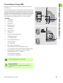
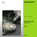
CNC PILOT 4290 B and Y Axis
CNC PILOT 4290
B and Y Axis
This manual describes functions and features that are available for the
B axis, the Y axis and the tool magazine in the CNC PILOT 4290 with
NC software number 625 952-xx (Release 7.1). This manual is a
supplement to the CNC PILOT 4290 User's Manual.
2
B and Y Axis
1 B and Y Axis ..... 7
1.1 Basics ..... 8
The Y axis ..... 8
The B axis ..... 8
The tool magazine ..... 10
1.2 Manual Control and Automatic Modes ..... 11
Automatic mode without reference run ..... 11
Magazine list ..... 11
Working with magazine tools ..... 14
Measuring and compensating magazine tools ..... 18
Tool compensation in automatic mode ..... 19
1.3 Programming Notes ..... 20
Milling contour position ..... 20
Cutting limit ..... 20
Drilling and milling in a tilted plane ..... 21
1.4 DIN PLUS: Section Codes ..... 22
PLATE MAGZN. section ..... 22
FRONT_Y, REAR_SIDE_Y section ..... 22
SURFACE_Y section ..... 23
1.5 DIN PLUS: Contours in the XY Plane ..... 24
Starting point of contour G170 Geo ..... 24
Linear element G171 Geo ..... 24
Circular arc G172/G173 Geo ..... 25
Hole G370 Geo ..... 26
Linear slot G371 Geo ..... 26
Circular slot G372/G373 Geo ..... 27
Full circle G374 Geo ..... 27
Rectangle G375 Geo ..... 28
Eccentric polygon G377 Geo ..... 28
Linear pattern in XY plane, G471-Geo ..... 29
Circular pattern in XY plane, G472 Geo ..... 30
Single surface G376 Geo ..... 31
Centric polygon G477 Geo ..... 31
HEIDENHAIN CNC PILOT 4290
3
1.6 DIN PLUS: Contours in the YZ Plane ..... 32
Starting point of contour G180 Geo ..... 32
Linear element G181 Geo ..... 32
Circular arc G182/G183 Geo ..... 33
Hole G380 Geo ..... 34
Linear slot G381 Geo ..... 34
Circular slot G382/G383 Geo ..... 35
Full circle G384 Geo ..... 35
Rectangle G385 Geo ..... 36
Eccentric polygon G387 Geo ..... 36
Linear pattern in YZ plane, G481-Geo ..... 37
Circular pattern in YZ plane, G482-Geo ..... 38
Single surface G386 Geo ..... 39
Centric polygon G487 Geo ..... 39
1.7 DIN PLUS: Working Planes ..... 40
Tilting the working plane G16 ..... 41
1.8 DIN PLUS (Y Axis): Positioning Commands ..... 42
Rapid traverse G0 ..... 42
Approach tool change point G14 ..... 42
Rapid traverse to machine coordinates G701 ..... 43
1.9 DIN PLUS: Magazine Tools ..... 44
Insert magazine tool G714 ..... 44
Define tool position G712 ..... 47
Preselect tool G600 ..... 48
1.10 DIN PLUS: Linear and Circular Paths ..... 49
Milling: Linear movement G1 ..... 49
Milling: Circular movement G2, G3—incremental center coordinates ..... 50
Milling: Circular path G12, G13—absolute center coordinates ..... 51
1.11 DIN PLUS (Y Axis): Milling Cycles ..... 52
Area milling—roughing G841 ..... 52
Area milling—finishing G842 ..... 53
Centric polygon milling—roughing G843 ..... 54
Centric polygon milling—finishing G844 ..... 55
Pocket milling - roughing G845 (Y axis) ..... 56
Pocket milling—finishing G846 (Y axis) ..... 61
Engrave in XY plane G803 ..... 63
Engrave in YZ plane G804 ..... 64
Thread milling in XY plane G800 ..... 65
Thread milling in YZ plane G806 ..... 66
Hobbing G808 ..... 67
1.12 Simulation ..... 68
Simulation of the tilted plane ..... 68
Displaying the coordinate system ..... 69
Position display with the B and Y axes ..... 69
4
1.13 TURN PLUS: Tool Magazine and B Axis ..... 70
Tool magazine ..... 70
Tools for the B axis ..... 70
1.14 TURN PLUS: Y Axis ..... 71
Y axis - Basics ..... 71
Definition of milling contours ..... 72
1.15 TURN PLUS: XY Plane Contours ..... 73
Reference data - XY front/XYR back ..... 73
XY plane: Starting point of contour ..... 74
XY plane: Linear element ..... 75
XY plane: Arc ..... 76
XY plane: Single hole ..... 77
XY plane: Circle (full circle) ..... 79
XY plane: Rectangle ..... 80
XY plane: Polygon ..... 81
XY plane: Linear slot ..... 82
XY plane: Circular slot ..... 83
XY plane: Linear drilling pattern ..... 84
XY plane: Circular drilling pattern ..... 85
XY plane: Linear figure pattern ..... 86
XY plane: Circular figure pattern ..... 87
XY plane: Single surface ..... 88
XY plane: Centric polygon ..... 88
1.16 TURN PLUS: YZ Plane Contours ..... 89
Reference data - Y lateral surface ..... 89
YZ plane: Starting point of contour ..... 89
YZ plane: Linear element ..... 90
YZ plane: Arc ..... 91
YZ plane: Single hole ..... 92
YZ plane: Circle (full circle) ..... 94
YZ plane: Rectangle ..... 95
YZ plane: Polygon ..... 96
YZ plane: Linear slot ..... 97
YZ plane: Circular slot ..... 98
YZ plane: Linear drilling pattern ..... 99
YZ plane: Circular drilling pattern ..... 100
YZ plane: Linear figure pattern ..... 101
YZ plane: Circular figure pattern ..... 102
Single surface in YZ plane ..... 103
Centric polygons in YZ plane ..... 103
1.17 Example Programs ..... 104
Machining with the Y axis ..... 104
Machining with the B axis ..... 109
HEIDENHAIN CNC PILOT 4290
5
B and Y Axis
HEIDENHAIN CNC PILOT 4290
7
1.1 Basics
1.1 Basics
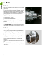
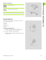
The Y axis
With a Y axis you can drill and mill a workpiece on its front, back and
lateral surfaces.
During use of the Y-axis, two axes interpolate linearly or circularly in
the given working plane, while the third axis interpolates linearly. This
enables you to machine slots or pockets, for example, with plane
floors and perpendicular edges. By defining the spindle angle, you can
determine the position of the milling contour on the workpiece.
The CNC PILOT supports part program creation with the Y axis in:
DIN PLUS
TURN PLUS contour definition
TURN PLUS working plan generation
The separation of contour description and machining also applies to
milling with the Y axis. Contour regeneration is not available for milling
operations.
Y axis contours are identified with section codes.
The graphical simulation shows the milling operation in the familiar
lathe, front, and surface windows, as well as in the "side view (YZ)."
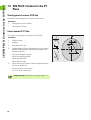
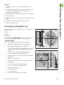
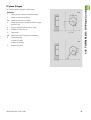
The B axis
Tilted working plane
The B axis makes it possible to drill, bore and mill in oblique planes. To
make programming easy, the coordinate system is tilted in such a way
that you can define the drilling patterns and milling contours in the YZ
plane. The actual drilling or milling operation is then performed in the
tilted plane.
The separation of contour description and machining also applies to
machining operations in tilted planes. Contour regeneration is not
available.
Contours in tilted planes are identified with the section code
SURFACE_Y.
The CNC PILOT supports part program creation with the B axis in DIN
PLUS.
The graphical simulation shows the machining operation in a tilted
working plane in the familiar lathe and front windows, as well as in the
“side view (YZ).”
8
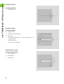
B90
In this way, you need fewer tools and fewer tool changes.
B0
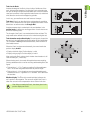
Another parameter that is maintained in the tool database is the
position angle. It defines the working positions of tools that are not
driven tools (turning tools).
Tool orientation and position display: For turning tools, the position
the tool tip is calculated based on the orientation of the cutting edge.
This orientation is not regenerated automatically when the B axis is
tilted and/or rotated.
2
1
3
4
8
O=
Display with black digits: Position display is valid.
Display with gray digits: Position display is invalid.
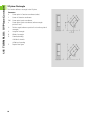
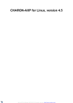
When orienting tools, the control distinguishes between roughing,
finishing and button tools as well as recessing and threading tools (see
figure).
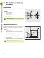
B90
G714 B.. C180
The tilt angle of the B axis is not maintained with the tool data. This
angle needs to be defined in the tool call or when inserting the tool.
After moving the B axis, please check whether the orientation is still
valid and reassign it, if necessary.
B180
G714 B.. C0
Tool data: All tools are described in the tool database by specifying
the X, Z and Y dimensions as well as the compensation values. These
dimensions are referenced to the tilt angle B=0°.
When the B axis has been moved manually, the control marks the
position display invalid.
1.1 Basics
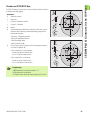
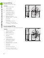
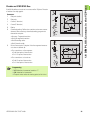
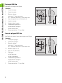
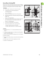
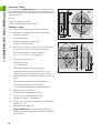
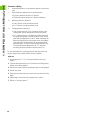
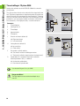
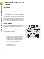
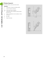
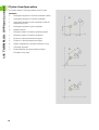
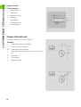
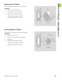
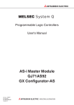
Tools for the B axis
Another advantage of the B axis is that it allows flexible use of the
tools during turning operations. By tilting the B axis and rotating the
tool you can bring it into positions that enable you to use one and the
same tool to machine in the longitudinal and transverse (or radial and
axial) directions on the main and opposing spindles.
5
7
6
Tool positions 1, 3, 5 or 7 apply to roughing, finishing and button
tools. The control recognizes neutral tools by the tool angle.
Tool positions 2, 4, 6 or 8 apply to recessing and threading tools.
Whether the tool is a “right-hand” or a “left-hand” tool is defined in
the tool data.
Machine display: The T box in the machine display indicates the
tool's pocket in the magazine. The current tilt angle of the B axis is
taken into account in the compensation values shown in this box.
After tilting or rotating the B axis, the values given in the
position display are invalid.
HEIDENHAIN CNC PILOT 4290
9
1.1 Basics
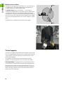
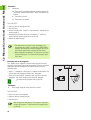
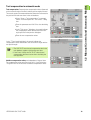
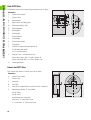
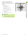
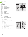
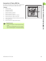
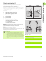
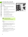
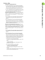
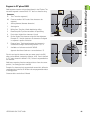
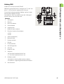
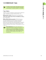
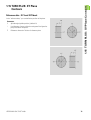
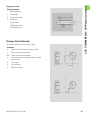
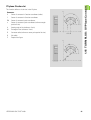
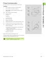
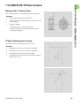
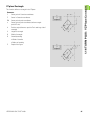
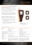
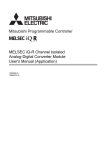
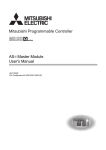
Multipoint tools for the B axis
If several tools are mounted on a tool holder, this is are referred to as
a “multipoint tool.” Each cutting edge (tool) of a multipoint tool is
assigned a separate ID number and description.
The position angle, which is identified by “C” in the figure, is
included in the tool data. When a cutting edge (tool) of a multipoint tool
is activated, the CNC PILOT will rotate the multipoint tool into the
correct position. The position is determined from the position angle, to
which the offset position angle from the tool change routine is added.
This allows inserting the tool either in the “normal” attitude or “upside
down.”
C240
C0
The photo shows a multipoint tool with three cutting edges.
C120
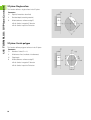
The tool magazine
The CNC PILOT supports a pocket-based tool magazine with up to 99
tools. Pocket-based means that each tool is assigned a specific pocket
in the magazine. The machine operator assigns the pockets when
setting up the magazine.
The magazine list indicates the current assignment of the tool
magazine. The tools are entered in this list with their ID numbers.
Tool programming: The magazine tools are intended for the B axis.
The command G714 is provided for changing and positioning the tools.
Alternatively, you can also use single commands (G0, G15, etc.) to
program a tilting of the B axis and a rotation of the tool to the position
angle. Please note, however, that you will need to declare the tool
position with G712 in that case.
10
1.2 Manual Control and Automatic Modes
1.2 Manual Control and Automatic
Modes
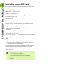
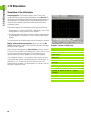
Automatic mode without reference run
As of software version 625 952-02:
You can start magazine programs and manual programs even if you
have not traversed the reference marks in all the axes. To use this
function, add a comment line to the program you want to start. In this
comment line you define which axes are allowed without a reference
status.
Syntax of the comment line:
[@0nn]—where nn stands for the address letters of the nonreferenced axes
Examples:
[@0B]—the B axis does not have to be referenced
[@0BY]—the B and Y axes do not have to be referenced
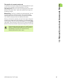
The functions for setting up the tool magazine and for
inserting the magazine tools are interfaced to the CNC
PILOT and the machine by the machine tool builder. The
functionality provided on your machine may therefore
differ from the functions described in this manual. Your
machine manual provides more detailed information.
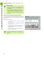
Magazine list
The magazine list indicates the current assignment of the tool
magazine. When setting up the magazine list, you assign each tool a
specific magazine pocket by entering the tool's ID number. For a
multipoint tool, you can enter the ID number of any cutting edge of
the tool. From that ID number, the CNC PILOT determines all other
cutting edges of the multipoint tool, since all ID numbers of a
multipoint tool are interlinked in the tool database.
The tool magazine can be set up in different ways:
Adding tools to the magazine by using the loading hatch: see
“Adding tools to the magazine by using the loading hatch” on
page 12
Adding tools to the magazine from the machine working space:
see “Adding tools to the magazine from the machine working
space” on page 13
Removing tools from the magazine: see “Removing tools from
the magazine” on page 13
HEIDENHAIN CNC PILOT 4290
11
1.2 Manual Control and Automatic Modes
The tool life management also applies to magazine tools without
restriction.
Danger of collision
Compare the magazine list with the tools actually in the
tool magazine and check the tool data before executing
the part program.
The magazine list and the dimensions of the registered
tools must correspond to the tools actually present,
because the CNC PILOT used this data for all slide
movements, protective zone monitoring, and other slide
movements.
Adding tools to the magazine by using the loading hatch
You can add a tool to the magazine by inserting it through the loading
hatch and assigning the tool's ID number to a specific pocket of the
magazine list.
To enter the tool ID number:
U
Select “Setting up > Tool list > Setup list” in manual
control mode.
U
Place the cursor on the magazine pocket you want to
assign to the tool.
U
Select the tool's ID number from the database and
confirm, or press the INS key and type in the ID
number directly.
U
Rotate the tool magazine to the corresponding
position and insert the tool.
The functions “Compare tool list with NC program” and
“Load tool list from NC program” are not available for the
magazine list.
12
U
U
U
Insert the tool in the tool holder (in the machine's working space).
Select “T > Magazine > Load plate” in manual control mode. The
CNC PILOT opens the “Magazine: Load plate” dialog box.
Enter the parameters and click OK to close the dialog box. The
control loads the associated NC program.
U Activate the NC program with Cycle Start.
1.
1.2 Manual Control and Automatic Modes
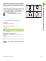
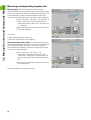
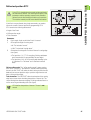
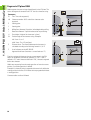
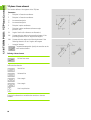
Adding tools to the magazine from the machine working space
Insert the tool in the tool holder and call the “Load plate” function.
Enter the ID number of the tool and the magazine pocket number. The
CNC PILOT inserts the tool in the magazine and enters the ID number
in the magazine list.
2.
ID . . .
P ...
3.
4.
B
Parameters
ID
ID number of the magazine tool.
P
Pocket number in the tool magazine.
B
B axis angle. Angle to which the B axis is tilted.
The CNC PILOT
inserts the tool in the magazine,
enters the tool in the magazine list,
moves the slide to the tool change position, and
tilts the B axis,
Note on operation and display: This function is executed
using an NC program. To activate the NC program, press
Cycle Start.
Removing tools from the magazine
Remove the tool from the magazine and delete the entry in the
magazine list.
U
U
U
Rotate the tool magazine to the corresponding position and remove
the tool.
Select “Setting up > Tool list > Setup list” in manual control mode.
Place the cursor on the magazine pocket of the tool you removed.
U Press the soft key or the DEL key and click yes on the
confirmation prompt. The control deletes the tool
from the magazine list.
HEIDENHAIN CNC PILOT 4290
13
1.2 Manual Control and Automatic Modes
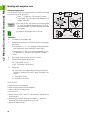
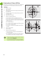
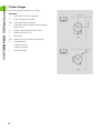
Working with magazine tools
Changing magazine tools
You can use this function to change the tool or to modify the tilt angle
or position angle of the active tool.
U
U
U
Select “T > Magazine > Tool change” in manual
control mode. The control opens the “Magazine: Tool
change” dialog box.
Press the soft key, select the tool from the magazine
list, enter the additional parameters and click OK to
close the dialog box. The control loads the associated
NC program.
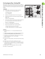
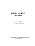
O
3
4
2
1
8
O=
B
5
6
7
C
C=0°
Orientation of turning tools. Position of the tool's cutting edge
(see figure).
Tool positions 1, 3, 5, 7: For roughing, finishing and button
tools (neutral tools are recognized by the tool angle).
Tool positions 2, 4, 6, 8: For recessing and threading cycles
(a “right-hand” or “left-hand” tool is defined in the tool
data).
B
B axis angle. Angle to which the B axis is tilted.
C
Offset position angle of turning tools.
0°: Tool attitude “normal”
180°: Tool attitude “upside down”
H
Shoe brake
0: The brake is locked depending on the tool parameter (if
“not driven” the brake is locked; if “driven” the brake is not
locked)
1: The brake is locked
2: The brake is not locked
The CNC PILOT
inserts the tool in the magazine,
takes the specified tool from the magazine,
moves to the tool change position,
tilts the B axis,
rotates the tool to the “normal” or “upside down” attitude (offset
position angle C),
calculates the tool data, taking the “orientation O,” the B axis
position and the position angle into account, and
adjusts the brake settings.
14
0°
Activate the NC program with Cycle Start.
Parameters
ID
ID number of the magazine tool.
O
B
TM
C=180°
1.2 Manual Control and Automatic Modes
Changing the tool position: If the call refers to the active tool, the
slide moves to the tool change position and tilts the B axis or rotates
the tool to the position angle.
Offset position angle: With the “offset position angle” you can
position turning tools in the “normal” attitude or “upside down.”
When positioning the tool, the CNC PILOT also takes the basic setting
saved in the tool database into account (position angle = position angle
from the tool data + offset position angle).
Tool orientation: The CNC PILOT takes the orientation of the cutting
edge into account when calculating the position of the tool tip. The
control distinguishes between roughing, finishing and button tools as
well as recessing and threading tools (see figure).
Note on operation and display: This function is executed
using an NC program. To activate the NC program, press
Cycle Start.
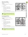
Declaring magazine tools
If there is a tool in the machine's working space when the control is
switched off and on again, the tool needs to be redeclared. In the
corresponding dialog box, the CNC PILOT automatically suggests the
values in effect when the control was switched off.
U
U
U
Select “T > Magazine > Manual tool” in manual
control mode. The control opens the “Magazine:
Manual tool” dialog box.
Press the soft key, enter the B axis angle, check all
other parameters and click OK to close the dialog box.
The control loads the associated NC program.
O
3
4
2
1
8
O=
5
B
TM
6
B
7
C
Activate the NC program with Cycle Start.
C=0°
C=180°
Parameters
ID
ID number of the magazine tool.
P
Pocket number in the tool magazine.
O
Orientation of turning tools. Position of the tool's cutting edge
(see figure).
Tool positions 1, 3, 5, 7: For roughing, finishing and button
tools (neutral tools are recognized by the tool angle).
Tool positions 2, 4, 6, 8: For recessing and threading cycles
(a “right-hand” or “left-hand” tool is defined in the tool
data).
B
B axis angle. Angle to which the B axis is tilted.
C
Offset position angle of turning tools.
0°: Tool attitude “normal”
180°: Tool attitude “upside down”
HEIDENHAIN CNC PILOT 4290
15
1.2 Manual Control and Automatic Modes
Parameters
H
Shoe brake
0: The brake is locked depending on the tool parameter (if
“not driven” the brake is locked; if “driven” the brake is not
locked)
1: The brake is locked
2: The brake is not locked
The CNC PILOT
moves to the tool change position,
tilts the B axis,
rotates the tool to the “normal” or “upside down” attitude (offset
position angle C),
calculates the tool data, taking the “orientation O,” the B axis
position and the position angle into account, and
adjusts the brake settings.
The information on the tool in the tool holder is not
saved when the control is switched off. HEIDENHAIN
therefore recommends to remove magazine tools from
the working space before switching off the control.
Note on operation and display: This function is executed
using an NC program. To activate the NC program, press
Cycle Start.
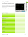
Returning tools to the magazine
The “Return tool to magazine” function moves the tool from the
machine's working space back into the magazine. The tool carrier then
approaches the tool change position and tilts the B axis to the
specified angle.
U
U
Select “T > Magazine > Return tool” in manual control mode. The
control opens the “Magazine: Return tool” dialog box.
Enter the “B axis angle B” parameter and click OK to close the
dialog box. The control loads the associated NC program.
U Activate the NC program with Cycle Start.
Parameters
B
B axis angle. Angle to which the B axis is tilted.
The CNC PILOT
inserts the tool in the magazine,
moves to the tool change position,
tilts the B axis,
Note on operation and display: This function is executed
using an NC program. To activate the NC program, press
Cycle Start.
16
TM 0
B
1.2 Manual Control and Automatic Modes
Tilting the B axis in manual control mode
You can either use the tool change call for positioning the B axis or you
can tilt the axis manually with the handwheel or PLC keys.
Tool change call: When you call the tool change function, the entries
default to the current values. Specify the required B axis angle and
activate the function.
Manual tilting: The B axis is tilted by using the handwheel. You can
also move the B axis with the PLC keys if your control has been
specially prepared for this functionality by the machine tool builder.
Your machine manual provides more detailed information.
When you tilt the B axis manually, the new B axis angle is taken into
account, but a change in the tool orientation is not recognized. The
control therefore marks the actual position displays for X and Z invalid
(gray digits). In the next tool call, the CNC PILOT newly calculates the
position of the tool tip and marks the position displays for X and Z valid.
Please note that the position displays for X and Z (machine
display) will display invalid values as soon as the B axis is
tilted manually. The CNC PILOT indicates this by
displaying the position values in gray.
HEIDENHAIN CNC PILOT 4290
17
1.2 Manual Control and Automatic Modes
Measuring and compensating magazine tools
Measuring tools: The function determines the tool lengths
referenced to the current tilt angle of the B axis and the position angle
of the tool. These are the values that are indicated on the display. The
control additionally converts the measured data into dimensions
referenced to the position B=0 and saves them in the tool database.
U
Select “Setting up > Tool set-up > Tool measuring” in
manual control mode. The control indicates the
current measurement values in the “Tool measuring
T...” dialog box.
U
Measure and enter the tool dimensions and click OK
to close the dialog box.
The control
deletes the compensation values and
enters the tool dimensions in the database.
Determining compensation values: The compensation values are
determined and displayed referenced to the current tilt angle of the B
axis and the position angle of the tool. The control converts the
measured data into dimensions referenced to the position B=0 and
saves them in the tool database.
U
Select “Setting up > Tool set-up > Tool
compensation” in manual control mode. In the
“Scratch tool” dialog box, the control indicates the
current compensation values referenced to position
B=0.
U
Determine the compensation values and click OK to
close the dialog box.
The control applies the compensation values.
18
1.2 Manual Control and Automatic Modes
Tool compensation in automatic mode
Tool compensation: Determine the compensation values referenced
to the current tilt angle of the B axis and the position angle of the tool.
The control converts the measured data into dimensions referenced to
the position B=0 and saves them in the tool database.
U
Select “Comp > Tool compensation” in automatic
mode. The control opens the “Tool correct.” dialog
box.
U
Enter the parameters and click OK to close the dialog
box.
U
In the “Tool correct.” dialog box, the control indicates
the compensation values referenced to the B axis
angle specified in the previous dialog box.
U
Enter the new compensation values.
In the “T” box (machine display), the control indicates the
compensation values referenced to the current B axis angle and the
tool position angle.
The CNC PILOT saves the tool compensation data in the
tool database, together with the other tool data.
If the B axis is tilted, the CNC PILOT takes the tool
compensation data into account when calculating the
tool tip position.
Additive compensation values are independent of the tool data.
The compensation values are effective in the X, Y and Z directions.
Tilting the B axis has no influence on additive compensation values.
HEIDENHAIN CNC PILOT 4290
19
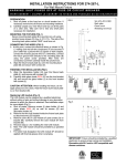
1.3 Programming Notes
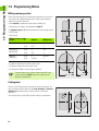
1.3 Programming Notes
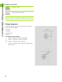
Milling contour position
Define the reference plane or the reference diameter in the section
code. Specify the depth and position of a milling contour (pocket,
island) in the contour definition:
With depth P programmed in the previous G308 cycle.
Alternatively on figures: Cycle parameter depth P.
The algebraic sign of “P” defines the position of the milling contour:
P<0: Pocket
P>0: Island
Milling contour position
Section
P
Surface
Milling floor
STIRN [FRONT]
P<0
Z
Z+P
P>0
Z+P
Z
RUECKSEITE
[REAR SIDE]
P<0
Z
Z–P
P>0
Z–P
Z
MANTEL
[SURFACE]
P<0
X
X+(P*2)
P>0
X+(P*2)
X
X: Reference diameter from the section code
Z: Reference plane from the section code
P: Depth from G308 or from the figure definition
The area milling cycles mill the surface specified in the
contour definition. Islands within this surface are not
taken into consideration.
Cutting limit
If parts of the milling contour lie outside of the turning contour, you
must limit the machining area with the area diameter X / reference
diameter X (parameters of the section code or of the figure
definition).
The cutting limits are also effective when milling in a tilted plane.
20
1.3 Programming Notes
Drilling and milling in a tilted plane
HEIDENHAIN recommends tilting the coordinate system in such a
way that you can define the drilling patterns and milling contours in the
YZ plane. This has the advantage that you can then use all the contour,
figure and pattern definitions for the YZ plane.
The drilling and milling cycles themselves are executed in the tilted
plane. These cycles determine the position of the tilted plane from the
contour definitions.
It is also a good idea to tilt the B axis with G714 because this G
function includes the calculation of the tool position.
The following programming sequence is thus recommended:
Rotate and shift the coordinate system for the tilted plane with the
section code SURFACE_Y (see “SURFACE_Y section” on page 23).
Define the drilling patterns and milling contours in the YZ plane.
Position the B axis with G714.
Activate the YZ plane with G19.
Use the drilling and milling cycles for machining.
Alternatively, you can tilt the working plane with G16 and then execute
the machining operations in the tilted plane.
Please note that the tool orientation is not regenerated automatically
when you position the B axis with the single commands G0 or G15.
Program G712 to have the tool position recalculated.
HEIDENHAIN CNC PILOT 4290
21
1.4 DIN PLUS: Section Codes
1.4 DIN PLUS: Section Codes
For lathes equipped with a tool magazine and/or a Y axis, the following
section codes are available.
PLATE MAGZN. section
In the PLATE MAGZN. section, you list all the tools that are used in the
NC program. This list is used when programming G714 (insert
magazine tool). The entries can be made in any order.
To create/edit the list of magazine tools:
U
Select “Head > Set up tool list.”
U
Select the tools from the database and enter them in
the list.
U
Press the ESC key to conclude the list.
To enter or edit individual magazine tools:
U
Position the cursor in the PLATE MAGZN. section.
U
To enter a new tool: Press the INS key.
U
To edit a tool: Press RETURN or double-click with the
left mouse button.
U
Edit the “Set up tool list” dialog box.
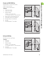
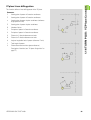
FRONT_Y, REAR_SIDE_Y section
The section code identifies the XY plane (G17) and the reference plane
of the contour (Z direction).
Parameters
X
Area diameter (as cutting limit)
Z
Position of the reference plane—default: 0
C
Spindle position—default: 0
22
1.4 DIN PLUS: Section Codes
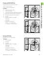
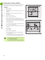
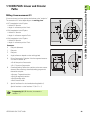
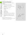
SURFACE_Y section
The section code identifies the YZ plane (G19). For machines equipped
with a B axis, it defines the tilted plane.
B, I, K
Without B axis: The reference diameter defines the contour position
in the X direction; the C axis angle defines the position on the
workpiece.
I
X
Parameters
X
Reference diameter
C
H=0
B
H=1
I
C axis angle—Defines the spindle position
Z
K
With B axis (see figures): SURFACE_Y additionally performs the
following transformations and rotations for the tilted plane:
Shifts the coordinate system to the position I, K
Rotates the coordinate system by the angle B; reference point: I, K
H=0: Shifts the rotated coordinate system by –I. The coordinate
system is moved “back.”
Parameters
X
Reference diameter
C
C axis angle—Defines the spindle position
B
Plane angle: Positive Z axis
I
Plane reference in X direction (radius)
K
Plane reference in Z direction
H
Automatic shift of the coordinate system (default: 0)
X
X
B
B
Z
Z
0: The rotated coordinate system is shifted by –I
1: The coordinate system is not shifted
Shifting “back” coordinate system: The CNC PILOT evaluates the
reference diameter for the cutting limit. This value is also used as the
reference value for the depth that you program for drilling operations
and milling contours.
Since the reference diameter is referenced to the current zero point,
it is recommended when working in a tilted plane, to shift the rotated
coordinate system “back” by the distance –I. If the cutting limits are
not needed, for example for drilling holes, you can disable the shift of
the coordinate system (H=1) and set the reference diameter to 0.
Example: “SURFACE_Y”
PROGRAMMKOPF [PROGRAM HEAD]
...
CONTOUR Q1 X0 Z600
ROHTEIL [BLANK]
...
FERTIGTEIL [FINISHED PART]
Please note:
...
X is the infeed axis in a tilted coordinate system. X
coordinates are entered as diameter coordinates.
Mirroring the coordinate system has no effect on the
reference axis of the tilt angle (“B axis angle” of G714).
MANTEL_Y X118 C0 B130 I59 K0 [SURFACE_Y]
HEIDENHAIN CNC PILOT 4290
...
BEARBEITUNG [MACHINING]
...
23
1.5 DIN PLUS: Contours in the XY Plane
1.5 DIN PLUS: Contours in the XY
Plane
Starting point of contour G170 Geo
G170 defines the starting point of a contour in the XY plane.
Parameters
X
Starting point of contour (radius)
Y
Starting point of contour
Linear element G171 Geo
G171 defines a line segment in a contour of the XY plane.
Parameters
X
End point (radius)
Y
End point
A
Angle to positive X axis
B
Chamfer/rounding. Defines the transition to the next contour
element. When entering a chamfer/rounding, program the
theoretical end point.
No entry: Tangential transition
B=0: No tangential transition
B>0: Rounding radius
B<0: Chamfer width
Q
Point of intersection. End point if the line segment intersects
a circular arc (default: 0):
Q=0: Near point of intersection
Q=1: Far point of intersection
Programming X, Y: Absolute, incremental, modal or “?”
24
1.5 DIN PLUS: Contours in the XY Plane
Circular arc G172/G173 Geo
G172/G173 defines a circular arc in a contour of the XY plane. Direction
of rotation: See help graphic
Parameters
X
End point (radius)
Y
End point
I
Center in X direction (radius)
J
Center in Y direction
R
Radius
B
Chamfer/rounding. Defines the transition to the next contour
element. When entering a chamfer/rounding, program the
theoretical end point.
No entry: Tangential transition
B=0: No tangential transition
B>0: Rounding radius
B<0: Chamfer width
Q
Point of intersection. End point if the line segment intersects
a circular arc (default: 0):
For a transition to a line segment:
Q=0: Near point of intersection
Q=1: Far point of intersection
For a transition to a circular arc:
Q=0: Far point of intersection
Q=1: Near point of intersection
Programming
X, Y: Absolute, incremental, modal or “?”
I, J: Absolute or incremental
End point must not be the starting point (no full circle).
HEIDENHAIN CNC PILOT 4290
25
1.5 DIN PLUS: Contours in the XY Plane
Hole G370 Geo
G370 defines a hole with countersinking and thread in the XY plane.
Parameters
X
Center of hole (radius)
Y
Center of hole
B
Hole diameter
P
Depth of hole (excluding point)
W
Point angle (default: 180°)
R
Sinking diameter
U
Sinking depth
E
Sinking angle
I
Thread diameter
J
Thread depth
K
Thread runout length
F
Thread pitch
V
Left-hand or right-hand thread (default: 0)
V=0: Right-hand thread
V=1: Left-hand thread
A
Angle to Z axis – inclination of the hole
Front face (range: –90° < A < 90°)—default: 0°
Rear side (range: 90° < A < 270°)—default: 180°
O
Centering diameter
Linear slot G371 Geo
G371 defines the contour of a linear slot in the XY plane.
Parameters
X
Center of slot (radius)
Y
Center of slot
K
Slot length
B
Slot width
A
Angle of slot length (reference: positive X axis)—default: 0°
P
Depth/height (default: “P” from G308)
P<0: Pocket
P>0: Island
I
Area diameter (as cutting limit)
No entry: “X” from section code
“I” overwrites “X” from section code
26
1.5 DIN PLUS: Contours in the XY Plane
Circular slot G372/G373 Geo
G372/G373 defines a circular slot in the XY plane.
G372: Circular slot clockwise
G373: Circular slot counterclockwise
Parameters
X
Center of slot curvature (radius)
Y
Center of slot curvature
R
Curvature radius (reference: center point path of the slot)
A
Starting angle; reference: positive X axis (default: 0°)
W
End angle; reference: positive X axis (default: 0°)
B
Slot width
P
Depth/height (default: “P” from G308)
P<0: Pocket
P>0: Island
I
Area diameter (as cutting limit)
No entry: “X” from section code
“I” overwrites “X” from section code
Full circle G374 Geo
G374 defines a full circle in the XY plane.
Parameters
X
Circle center (radius)
Y
Circle center
R
Circle radius
P
Depth/height (default: “P” from G308)
P<0: Pocket
P>0: Island
I
Area diameter (as cutting limit)
No entry: “X” from section code
“I” overwrites “X” from section code
HEIDENHAIN CNC PILOT 4290
27
1.5 DIN PLUS: Contours in the XY Plane
Rectangle G375 Geo
G375 defines a rectangle in the XY plane.
Parameters
X
Center of rectangle (radius)
Y
Center of rectangle
K
Length of rectangle
B
(Height) width of rectangle
R
Chamfer/rounding (default: 0)
R>0: Radius of rounding arc
R<0: Chamfer width
A
Angle to X axis (default: 0°)
P
Depth/height (default: “P” from G308)
P<0: Pocket
P>0: Island
I
Area diameter (as cutting limit)
No entry: “X” from section code
“I” overwrites “X” from section code
Eccentric polygon G377 Geo
G377 defines the contour of an eccentric polygon in the XY plane.
Parameters
X
Center point of polygon (radius)
Y
Center point of polygon
Q
Number of edges (Q >= 3)
A
Angle to X axis (default: 0°)
K
Edge length
K>0: Edge length
K<0: Inside diameter
R
Chamfer/rounding—default: 0
R>0: Radius of rounding arc
R<0: Chamfer width
P
Depth/height (default: “P” from G308)
P<0: Pocket
P>0: Island
I
Area diameter (as cutting limit)
No entry: “X” from section code
“I” overwrites “X” from section code
28
1.5 DIN PLUS: Contours in the XY Plane
Linear pattern in XY plane, G471-Geo
G471 defines a linear pattern in the XY plane. G471 affects the hole or
figure defined in the following block (G370 to G375, G377).
Parameters
Q
Number of figures
X
Starting point of pattern (radius)
Y
Starting point of pattern
I
End point of pattern (X direction; radius)
J
End point of pattern (Y direction)
Ii
Distance in X direction between two figures
Ji
Distance in Y direction between two figures
A
Angle of longitudinal axis to X axis
R
Total length of pattern
Ri
Distance between two figures (pattern distance)
Programming notes
Program the hole/figure in the following block without a
center.
The milling cycle (MACHINING section) calls the hole/
figure in the following block - not the pattern definition.
HEIDENHAIN CNC PILOT 4290
29
1.5 DIN PLUS: Contours in the XY Plane
Circular pattern in XY plane, G472 Geo
G472 defines a circular pattern in the XY plane. G472 is effective for
the figure defined in the following block (G370 to G375, G377).
Parameters
Q
Number of figures
K
Pattern diameter
A
Starting angle—position of the first figure; reference: positive
X axis (default: 0°)
W
End angle—position of the last figure; reference: positive X
axis; (default: 360°)
Wi
Angle between two figures
V
Direction—orientation (default: 0)
V=0, without W: Figures are arranged on a full circle
V=0, with W: Figures are arranged on the longer circular arc
V=0, with Wi: The algebraic sign of Wi defines the direction
(Wi<0: clockwise)
V=1, with W: Clockwise
V=1, with Wi: Clockwise (algebraic sign of Wi has no effect)
V=2, with W: Counterclockwise
V=2, with Wi: Counterclockwise (algebraic sign of Wi has
no effect)
X
Center of pattern (radius)
Y
Center of pattern
H
Position of the figures (default: 0)
H=0: Normal position; the figures are rotated about the
circle center (rotation)
H=1: Original position; the position of the figures relative to
the coordinate system remains unchanged (translation)
Program the hole/figure in the following block without a
center. Exception: circular slot.
The milling cycle (MACHINING section) calls the hole/
figure in the following block—not the pattern definition.
30
1.5 DIN PLUS: Contours in the XY Plane
Single surface G376 Geo
G376 defines a surface in the XY plane.
Parameters
Z
Reference edge (default: “Z” from section code)
K
Residual depth
Ki
Depth
B
Width (reference: reference edge Z)
B<0: Surface in negative Z direction
B>0: Surface in positive Z direction
I
Surface diameter
No entry: “X” from section code
“I” overwrites “X” from section code
C
Angular position of surface (default: “C” from section code)
Whether the surface lies on the front face or rear side
has no effect on the evaluation of the algebraic sign for
“width B.”
Centric polygon G477 Geo
G477 defines polygonal surfaces in the XY plane.
Parameters
Z
Reference edge (default: “Z” from section code)
K
Inside diameter (width across flats)
Ki
Length of side
B
Width (reference: reference edge Z)
B<0: Surface in negative Z direction
B>0: Surface in positive Z direction
Q
Number of sides (Q >= 2)
I
Surface diameter
No entry: “X” from section code
“I” overwrites “X” from section code
C
Angular position of surface (default: “C” from section code)
Whether the surface lies on the front face or rear side
has no effect on the evaluation of the algebraic sign for
“width B.”
HEIDENHAIN CNC PILOT 4290
31
1.6 DIN PLUS: Contours in the YZ Plane
1.6 DIN PLUS: Contours in the YZ
Plane
Starting point of contour G180 Geo
G180 defines the starting point of a contour in the YZ plane.
Parameters
Y
Starting point of contour
Z
Starting point of contour
Linear element G181 Geo
G181 defines a line segment in a contour of the YZ plane.
Parameters
Y
End point
Z
End point
A
Angle to positive Z axis
B
Chamfer/rounding. Defines the transition to the next contour
element. When entering a chamfer/rounding, program the
theoretical end point.
No entry: Tangential transition
B=0: No tangential transition
B>0: Rounding radius
B<0: Chamfer width
Q
Point of intersection. End point if the line segment intersects
a circular arc (default: 0):
Q=0: Near point of intersection
Q=1: Far point of intersection
Programming Y, Z: Absolute, incremental, modal or “?”
32
1.6 DIN PLUS: Contours in the YZ Plane
Circular arc G182/G183 Geo
G182/G183 defines a circular arc in a contour of the YZ plane. Direction
of rotation: See help graphic
Parameters
Y
End point (radius)
Z
End point
J
Center (Y direction)
K
Center (Z direction)
R
Radius
B
Chamfer/rounding. Defines the transition to the next contour
element. When entering a chamfer/rounding, program the
theoretical end point.
No entry: Tangential transition
B=0: No tangential transition
B>0: Rounding radius
B<0: Chamfer width
Q
Point of intersection. End point if the line segment intersects
a circular arc (default: 0):
For a transition to a line segment:
Q=0: Near point of intersection
Q=1: Far point of intersection
For a transition to a circular arc:
Q=0: Far point of intersection
Q=1: Near point of intersection
Programming
Y, Z: Absolute, incremental, modal or “?”
J, K: Absolute or incremental
End point must not be the starting point (no full circle).
HEIDENHAIN CNC PILOT 4290
33
1.6 DIN PLUS: Contours in the YZ Plane
Hole G380 Geo
G380 defines a single hole with countersinking and thread in the YZ
plane.
Parameters
Y
Center of hole
Z
Center of hole
B
Diameter of hole
P
Depth of hole (excluding point)
W
Point angle (default: 180°)
R
Sinking diameter
U
Sinking depth
E
Sinking angle
I
Thread diameter
J
Thread depth
K
Start of thread (runout length)
F
Thread pitch
V
Left-hand or right-hand thread (default: 0)
V=0: Right-hand thread
V=1: Left-hand thread
A
Angle to X axis; range: –90° < A < 90°
O
Centering diameter
Linear slot G381 Geo
G381 defines the contour of a linear slot in the YZ plane.
Parameters
Y
Center of slot
Z
Center of slot
X
Reference diameter
No entry: “X” from section code
“X” from G381 overwrites “X” from section code
A
Angle to Z axis (default: 0°)
K
Slot length
B
Slot width
P
Pocket depth (default: “P” from G308)
34
1.6 DIN PLUS: Contours in the YZ Plane
Circular slot G382/G383 Geo
G382/G383 defines a circular slot in the YZ plane.
G382: Circular slot clockwise
G383: Circular slot counterclockwise
Parameters
Y
Center of slot curvature
Z
Center of slot curvature
X
Reference diameter
No entry: “X” from section code
“X” from G381 overwrites “X” from section code
R
Radius; reference: center point path of the slot
A
Starting angle; reference: X axis (default: 0°)
W
End angle; reference: X axis (default: 0°)
B
Slot width
P
Pocket depth (default: “P” from G308)
Full circle G384 Geo
G384 defines a full circle in the YZ plane.
Parameters
Y
Circle center
Z
Circle center
X
Reference diameter
No entry: “X” from section code
“X” from G381 overwrites “X” from section code
R
Circle radius
P
Pocket depth (default: “P” from G308)
HEIDENHAIN CNC PILOT 4290
35
1.6 DIN PLUS: Contours in the YZ Plane
Rectangle G385 Geo
G385 defines a rectangle in the YZ plane.
Parameters
Y
Center of rectangle
Z
Center of rectangle
X
Reference diameter
No entry: “X” from section code
“X” from G381 overwrites “X” from section code
A
Angle of longitudinal axis to Z axis (default: 0°)
K
Length of rectangle
B
(Height) width of rectangle
R
Chamfer/rounding (default: 0)
R>0: Radius of rounding arc
R<0: Chamfer width
P
Pocket depth (default: “P” from G308)
Eccentric polygon G387 Geo
G387 defines the contour of an eccentric polygon in the YZ plane.
Parameters
Y
Center point of polygon
Z
Center point of polygon
X
Reference diameter
No entry: “X” from section code
“X” from G381 overwrites “X” from section code
Q
Number of edges (Q >= 3)
A
Angle to Z axis (default: 0°)
K
Edge length
K>0: Edge length
K<0: Inside diameter
R
Chamfer/rounding—default: 0
R>0: Radius of rounding arc
R<0: Chamfer width
P
36
Pocket depth (default: “P” from G308)
1.6 DIN PLUS: Contours in the YZ Plane
Linear pattern in YZ plane, G481-Geo
G481 defines a linear pattern in the YZ plane. G481 is effective for the
figure defined in the following block (G380 to G385, G387).
Parameters
Q
Number of figures
Y
Starting point of pattern
Z
Starting point of pattern
J
End point of pattern (Y direction)
K
End point of pattern (Z direction)
Ji
Distance between two figures (in Y direction)
Ki
Distance between two figures (in Z direction)
A
Angle of longitudinal axis of pattern (reference: positive Z axis)
R
Total length of pattern
Ri
Distance between two figures (pattern distance)
Programming notes
Program the hole/figure in the following block without a
center.
The milling cycle (MACHINING section) calls the hole/
figure in the following block—not the pattern definition.
HEIDENHAIN CNC PILOT 4290
37
1.6 DIN PLUS: Contours in the YZ Plane
Circular pattern in YZ plane, G482-Geo
G482 defines a circular pattern in the YZ plane. G482 is effective for
the figure defined in the following block (G380 to G385, G387).
Parameters
Q
Number of figures
K
Pattern diameter
A
Starting angle—position of the first figure; reference: Z axis
(default: 0°)
W
End angle—position of the last figure; reference: Z axis
(default: 360°)
Wi
Angle between two figures
V
Direction—orientation (default: 0)
V=0, without W: Figures are arranged on a full circle
V=0, with W: Figures are arranged on the longer circular arc
V=0, with Wi: The algebraic sign of Wi defines the direction
(Wi<0: clockwise)
V=1, with W: Clockwise
V=1, with Wi: Clockwise (algebraic sign of Wi has no effect)
V=2, with W: Counterclockwise
V=2, with Wi: Counterclockwise (algebraic sign of Wi has
no effect)
Y
Center of pattern
Z
Center of pattern
H
Position of the figures (default: 0)
H=0: Normal position; the figures are rotated about the
circle center (rotation)
H=1: Original position; the position of the figures relative to
the coordinate system remains unchanged (translation)
Program the hole/figure in the following block without a
center. Exception: circular slot.
The milling cycle (MACHINING section) calls the hole/
figure in the following block—not the pattern definition.
38
1.6 DIN PLUS: Contours in the YZ Plane
Single surface G386 Geo
G386 defines a surface in the YZ plane.
Parameters
Z
Reference edge
K
Residual depth
Ki
Depth
B
Width (reference: reference edge Z)
B<0: Surface in negative Z direction
B>0: Surface in positive Z direction
X
Reference diameter
No entry: “X” from section code
“X” from G381 overwrites “X” from section code
C
Angular position of surface (default: “C” from section code)
The reference diameter X limits the surface to be
machined.
Centric polygon G487 Geo
G487 defines polygonal surfaces in the YZ plane.
Parameters
Z
Reference edge
K
Inside diameter (width across flats)
Ki
Length of side
B
Width (reference: reference edge Z)
B<0: Surface in negative Z direction
B>0: Surface in positive Z direction
X
Reference diameter
No entry: “X” from section code
“X” from G381 overwrites “X” from section code
C
Angular position of surface (default: “C” from section code)
Q
Number of sides (Q >= 2)
The reference diameter X limits the surface to be
machined.
HEIDENHAIN CNC PILOT 4290
39
1.7 DIN PLUS: Working Planes
1.7 DIN PLUS: Working Planes
When programming drilling or milling operations with the Y axis, you
need to define the working plane.
If no working plane is programmed, the CNC PILOT assumes a turning
operation or a milling operation with the C axis (G18 XZ plane).
As of software version 625 952-05: At the end of a machining program
(M30, M99) the working plane is reset to G18.
G17 XY plane (front or back)
Milling cycles are executed in the XY plane, with the depth feed for
milling and drilling cycles in the Z direction.
G18 XZ plane (turning)
In the XZ plane, “normal turning operations” as well as drilling and
milling operations are executed with the C axis.
G19 YZ plane (side view/surface)
Milling cycles are executed in the YZ plane, with the depth feed for
milling and drilling cycles in the X direction.
40
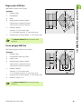
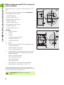
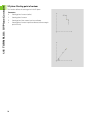
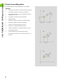
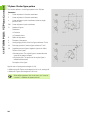
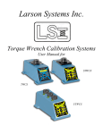
G16 executes the following transformations and rotations:
X
X
W
B
Parameters
B
Plane angle; reference: positive Z axis
I
U, W
B, I, K
Shifts the coordinate system to the position I, K
Rotates the coordinate system by the angle B; reference point: I, K
Shifts, if programmed, the coordinate system by U and W in the
rotated coordinate system
U
I
Z
Plane reference in X direction (radius)
K
Plane reference in Z direction
U
Shift in X direction
W
Shift in Z direction
Q
Enable/disable tilting the working plane
Z
K
0: Disable tilted working plane function
1: Tilt working plane
2: Restore previous G16 plane
G16 Q0 resets the working plane. The zero point and coordinate
system defined before G16 are then in effect again.
X
X
B
G16 Q2 restores the previous G16 plane.
B
Z
The positive Z axis is the reference axis for the “plane angle B.” This
also applies to a mirrored coordinate system.
Z
Please note:
X is the infeed axis in a tilted coordinate system. X
coordinates are entered as diameter coordinates.
Mirroring the coordinate system has no effect on the
reference axis of the tilt angle (“B axis angle” of G714).
Other zero point shifts are not permitted while G16 is
active.
Example: “G16”
. . .
BEARBEITUNG [MACHINING]
...
N.. G19
N.. G15 B130
N.. G16 B130 I59 K0 Q1
N.. G1 X.. Z.. Y..
N.. G16 Q0
. . .
HEIDENHAIN CNC PILOT 4290
41
1.7 DIN PLUS: Working Planes
Tilting the working plane G16
1.8 DIN PLUS (Y Axis): Positioning Commands
1.8 DIN PLUS (Y Axis): Positioning
Commands
Rapid traverse G0
G0 moves the tool at rapid traverse along the shortest path to the
target point X, Y, Z and tilts the B axis.
Parameters
X
Diameter—target point
Z
Length—target point
Y
Length—target point
B
Angle of the B axis
Programming X, Y, Z, B: Absolute, incremental or modal
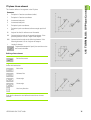
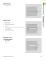
Approach tool change point G14
G14 moves the slide at rapid traverse to the tool change position. In
setup mode, define permanent coordinates for the tool change
position.
Parameters
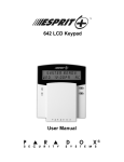
Q
Sequence (default: 0)
0: Move simultaneously in X and Z axes (diagonal path)
1: First X, then Z direction
2: First Z, then X direction
3: Only X direction, Z remains unchanged
4: Only Z direction, X remains unchanged
5: Y direction only
6: Move simultaneously in X, Y and Z axes (diagonal path)
If Q=0 to 4, the Y axis does not move.
42
B
Y
Z
Z
Y
X
X
1.8 DIN PLUS (Y Axis): Positioning Commands
Rapid traverse to machine coordinates G701
G701 moves the tool at rapid traverse along the shortest path to the
target point X, Y, Z and tilts the B axis.
Parameters
X
End point (diameter)
Y
End point
Z
End point
B
Angle of the B axis
“X, Y, Z“ refer to the machine zero point and the slide
reference point.
HEIDENHAIN CNC PILOT 4290
43
1.9 DIN PLUS: Magazine Tools
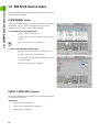
1.9 DIN PLUS: Magazine Tools
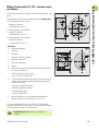
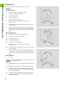
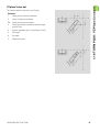
Insert magazine tool G714
B
O
Cycle G714 is interfaced to the control and the machine by
the machine tool builder. The following description of the
parameters and the operating sequence may therefore
deviate from the functionality provided on your machine.
The machine manual provides more detailed information.
3
4
Parameters
ID
ID number of the magazine tool.
Press the “Continue” soft key to display the plate list.
Highlight the required tool and confirm your selection.
O
Orientation of turning tools. Position of the tool's cutting edge
(see figure).
Tool positions 1, 3, 5, 7: For roughing, finishing and button
tools (neutral tools are recognized by the tool angle).
Tool positions 2, 4, 6, 8: For recessing and threading cycles
(a “right-hand” or “left-hand” tool is defined in the tool
data).
B
B axis angle. Angle to which the B axis is tilted.
C
Offset position angle of turning tools.
0°: Tool attitude “normal”
180°: Tool attitude “upside down”
D
Additive compensation (1 to 16). Activates the additive
compensation. The additive compensation is deactivated with
the next tool change (see G149).
H
Shoe brake
0: The brake is locked depending on the tool parameter (if
“not driven” the brake is locked; if “driven” the brake is not
locked)
1: The brake is locked
2: The brake is not locked
44
1
8
O=
5
G714 contains the following functions:
Move to the tool change position.
Return the active tool to the magazine.
Take the programmed tool from the magazine.
Tilt the B axis to the programmed angle.
Rotate the tool to the “position angle” (“normal” or “upside down”
attitude).
Calculate the tool data on the basis of the “orientation O,” the B axis
position and the position angle.
If programmed, activate the (additive) “compensation D.”
Set the shoe brake, as programmed.
2
B
6
7
C
C=0°
0°
V
C=180°
V
V0
V1
V2
V3
V4
V5
V6
V9
X+Z+Y
X+Z
X, Z
Z, X
X
Z
Y
X+Z+Y
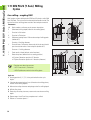
1.9 DIN PLUS: Magazine Tools
Parameters
V
Approach the tool change position (default: 6)
No entry: Move simultaneously in X, Y and Z directions.
0: Move simultaneously in X and Z directions
1: First X, then Z direction
2: First Z, then X direction
3: X direction only
4: Z direction only
5: Y direction only
6: Move simultaneously in X, Y and Z directions
9: Do not approach the tool change position
As of software version 625 952-02:
Parameters
Q
Additional functions
You can use this parameter to transfer a value to the tool
change. The function of this value is defined by the machine
tool builder.
X
Diameter
X diameter to which the tool moves at the end of the tool
change, if required.
Z
Length
Z position to which the tool moves at the end of the tool
change, if required.
Y
Length
Y position to which the tool moves at the end of the tool
change, if required.
Returning the tool to the magazine: If you program G714 without
an “ID number,” the CNC PILOT will return the active tool to the
magazine without inserting a new tool.
Changing the tool position: If the call refers to the active tool, the B
axis is tilted and/or the position angle is changed. In the parameter
“V,” you can define whether this function is to be executed at the
current position or at the tool change position.
Offset position angle: With the “offset position angle” you can
position turning tools in the “normal” attitude or “upside down.”
When positioning the tool, the CNC PILOT also takes the basic setting
saved in the tool database into account (position angle = position angle
from the tool data + offset position angle).
Tool orientation: The CNC PILOT takes the orientation of the cutting
edge into account when calculating the position of the tool tip. The
control distinguishes between roughing, finishing and button tools as
well as recessing and threading tools (see figure).
HEIDENHAIN CNC PILOT 4290
45
1.9 DIN PLUS: Magazine Tools
G16 active: If a tilted plane (G16) is active, it is deactivated while the
G714 call is executed. The tilted plane is then effective again after
G714.
HEIDENHAIN recommends using G714 also for changing
the tilt angle or tool position (offset position angle).
Example: G714
. . .
FERTIGTEIL [FINISHED PART]
. . .
SURFACE_Y X118 C0 B130 I59 K0
Describe the tilted working plane
. . .
BEARBEITUNG [MACHINING]
. . .
N . . G714 ID“B_522-32-10“ O0 B130
Insert the magazine tool; tilt the B axis
N . . G19
Activate the YZ plane
. . .
N . . G840 NS ..
Milling operation in tilted plane
. . .
N . . G18
Activate the XZ plane
N . . G714 ID“B_112-93-80“ O1 B90 C0
Insert the magazine tool; tilt the B axis; set the
offset position angle for the tool
. . .
N . . G810 NS ..
. . .
ENDE [END]
46
Turning
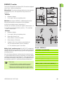
1.9 DIN PLUS: Magazine Tools
Define tool position G712
O
Cycle G712 is interfaced to the control and the machine by
the machine tool builder. The following description of the
parameters and the operating sequence may therefore
deviate from the functionality provided on your machine.
The machine manual provides more detailed information.
3
4
1
8
O=
5
If the B axis was positioned using single commands, you need to
inform the control of the tool position by programming G712.
B
2
6
B
7
C
G712 contains the following declarations:
Angle of the B axis
Offset position angle
Tool orientation
C=0°
C=180°
Parameters
B
B axis angle. Angle at which the B axis is located.
C
Offset position angle of turning tools.
0°: Tool attitude “normal”
180°: Tool attitude “upside down”
O
Orientation of turning tools. Position of the tool's cutting edge
(see figure).
Tool positions 1, 3, 5, 7: For roughing, finishing and button
tools (neutral tools are recognized by the tool angle).
Tool positions 2, 4, 6, 8: For recessing and threading cycles
(a “right-hand” or “left-hand” tool is defined in the tool
data).
Offset position angle: The “offset position angle” rotates turning
tools to the “normal” or “upside down” attitude. When positioning
the tool, the CNC PILOT also takes the basic setting saved in the tool
database into account (position angle = position angle from the tool
data + offset position angle).
Tool orientation: The CNC PILOT takes the orientation of the cutting
edge into account when calculating the position of the tool tip. The
control distinguishes between roughing, finishing and button tools as
well as recessing and threading tools (see figure).
G712 defines the position of the tool. The tool is not
moved.
HEIDENHAIN CNC PILOT 4290
47
1.9 DIN PLUS: Magazine Tools
Preselect tool G600
As of software version 625 952-04:
If your lathe is equipped with a tool magazine, you can use G600 for
special functions. G600 transfers the current magazine pocket number
of the tool to the PLC.
Parameters
ID
ID number of the magazine tool.
The G600 function is provided by the machine tool builder.
The machine manual provides more detailed information.
48
1.10 DIN PLUS: Linear and Circular Paths
1.10 DIN PLUS: Linear and Circular
Paths
Milling: Linear movement G1
G1 moves the tool on a linear path at the feed rate to the “end point.”
The execution of G1 varies depending on the working plane:
G17 Interpolation in the XY plane
Infeed in Z direction
Angle A—reference: positive X axis
G18 Interpolation in the XZ plane
Infeed in Y direction
Angle A—reference: negative Z axis
G19 Interpolation in the YZ plane
Infeed in X direction
Angle A—reference: positive Z axis
Parameters
X
End point (diameter)
Y
End point
Z
End point
A
Angle (reference: depends on the working plane)
Q
Point of intersection. End point if the line segment intersects
a circular arc (default: 0):
Q=0: Near point of intersection
Q=1: Far point of intersection
B
Chamfer/rounding. Defines the transition to the next contour
element. When entering a chamfer/rounding, program the
theoretical end point.
No entry: Tangential transition
B=0: No tangential transition
B>0: Rounding radius
B<0: Chamfer width
E
Special feed factor for the chamfer/rounding (default: 1)
Special feed rate = active feed rate * E (0 < E <= 1)
Programming X, Y, Z: Absolute, incremental or
modal or “?”
HEIDENHAIN CNC PILOT 4290
49
1.10 DIN PLUS: Linear and Circular Paths
Milling: Circular movement G2, G3—incremental
center coordinates
G2/G3 moves the tool in a circular arc at the feed rate to the “end
point.”
The execution of G2/G3 varies depending on the working plane:
G17 Interpolation in the XY plane
Infeed in Z direction
Center definition: with I, J
G18 Interpolation in the XZ plane
Infeed in Y direction
Center definition: with I, K
G19 Interpolation in the YZ plane
Infeed in X direction
Center definition: with J, K
Parameters
X
End point (diameter)
Y
End point
Z
End point
I
Incremental center point (radius)
J
Incremental center point
K
Incremental center point
R
Radius
Q
Point of intersection. End point if the line segment intersects
a circular arc (default: 0):
Q=0: Near point of intersection
Q=1: Far point of intersection
B
Chamfer/rounding. Defines the transition to the next contour
element. When entering a chamfer/rounding, program the
theoretical end point.
No entry: Tangential transition
B=0: No tangential transition
B>0: Rounding radius
B<0: Chamfer width
E
Special feed factor for the chamfer/rounding (default: 1)
Special feed rate = active feed rate * E (0 < E <= 1)
If you do not program the center, the CNC PILOT automatically
calculates the possible solutions for the center and chooses that point
as the center which results in the shortest arc.
Programming X, Y, Z: Absolute, incremental or
modal or “?”
50
1.10 DIN PLUS: Linear and Circular Paths
Milling: Circular path G12, G13—absolute center
coordinates
G12/G13 moves the tool in a circular arc at the feed rate to the “end
point.”
The execution of G12/G13 varies depending on the working plane:
G17 Interpolation in the XY plane
Infeed in Z direction
Center definition: with I, J
G18 Interpolation in the XZ plane
Infeed in Y direction
Center definition: with I, K
G19 Interpolation in the YZ plane
Infeed in X direction
Center definition: with J, K
Parameters
X
End point (diameter)
Y
End point
Z
End point
I
Absolute center point (radius)
J
Absolute center point
K
Absolute center point
R
Radius
Q
Point of intersection. End point if the line segment intersects
a circular arc (default: 0):
Q=0: Near point of intersection
Q=1: Far point of intersection
B
Chamfer/rounding. Defines the transition to the next contour
element. When entering a chamfer/rounding, program the
theoretical end point.
No entry: Tangential transition
B=0: No tangential transition
B>0: Rounding radius
B<0: Chamfer width
E
Special feed factor for the chamfer/rounding (default: 1)
Special feed rate = active feed rate * E (0 < E <= 1)
If you do not program the center, the CNC PILOT automatically
calculates the possible solutions for the center and chooses that point
as the center which results in the shortest arc.
Programming X, Y, Z: Absolute, incremental or
modal or “?”
HEIDENHAIN CNC PILOT 4290
51
1.11 DIN PLUS (Y Axis): Milling Cycles
1.11 DIN PLUS (Y Axis): Milling
Cycles
Area milling—roughing G841
G841 roughs surfaces defined with G376 Geo (XY plane) or with G386
Geo (YZ plane). The cycle mills from the outside toward the inside. The
tool moves to the working plane outside of the workpiece material.
Parameters
NS
Block number—reference to the contour description
P
(Maximum) milling depth (infeed in the working plane)
I
Oversize in X direction
K
Oversize in Z direction
U
(Minimum) overlap factor. Defines the overlap of milling paths
(default: 0.5).
Overlap = U*milling diameter
V
Overrun factor. Defines the distance by which the tool should
pass the outside radius of the workpiece (default: 0.5).
Overrun = V*milling diameter
F
Feed rate for infeed (default: active feed rate)
J
Retraction plane (default: back to starting position)
XY plane: Retraction position in Z direction
YZ plane: Retraction position in X direction (diameter)
Oversizes are taken into account:
G57: Oversize in X, Z direction
G58: Equidistant oversize in the milling plane
Cycle run
1
Starting position (X, Y, Z, C) is the position before the cycle
begins.
2
Calculate the proportioning of cuts (infeeds to the milling planes,
infeeds in the milling depths).
3
Move to the safety clearance and plunge to the first milling depth.
4
Mill the first plane.
5
Retract by the safety clearance, return and cut to the next milling
depth.
6
Repeat steps 4 and 5 until the complete area is milled.
7
Return to “retraction plane J.”
52
1.11 DIN PLUS (Y Axis): Milling Cycles
Area milling—finishing G842
G842 finishes surfaces defined with G376 Geo (XY plane) or G386 Geo
(YZ plane). The cycle mills from the outside toward the inside. The tool
moves to the working plane outside of the workpiece material.
Parameters
NS
Block number—reference to the contour description
H
Cutting direction for side finishing (default: 0)
H=0: Up-cut milling
H=1: Climb milling
P
(Maximum) milling depth (infeed in the working plane)
U
(Minimum) overlap factor. Defines the overlap of milling paths
(default: 0.5).
Overlap = U*milling diameter
V
Overrun factor. Defines the distance by which the tool should
pass the outside radius of the workpiece (default: 0.5).
Overrun = V*milling diameter
F
Feed rate for infeed (default: active feed rate)
J
Retraction plane (default: back to starting position)
XY plane: Retraction position in Z direction
YZ plane: Retraction position in X direction (diameter)
Cycle run
1
Starting position (X, Y, Z, C) is the position before the cycle
begins.
2
Calculate the proportioning of cuts (infeeds to the milling planes,
infeeds in the milling depths).
3
Move to the safety clearance and plunge to the first milling depth.
4
Mill the first plane.
5
Retract by the safety clearance, return and cut to the next milling
depth.
6
Repeat steps 4 and 5 until the complete area is milled.
7
Return to “retraction plane J.”
HEIDENHAIN CNC PILOT 4290
53
1.11 DIN PLUS (Y Axis): Milling Cycles
Centric polygon milling—roughing G843
G843 roughs centric polygons defined with G477 Geo (XY plane) or
G487 Geo (YZ plane). The cycle mills from the outside toward the
inside. The tool moves to the working plane outside of the workpiece
material.
Parameters
NS
Block number—reference to the contour description
P
(Maximum) milling depth (infeed in the working plane)
I
Oversize in X direction
K
Oversize in Z direction
U
(Minimum) overlap factor. Defines the overlap of milling paths
(default: 0.5).
Overlap = U*milling diameter
V
Overrun factor. Defines the distance by which the tool should
pass the outside radius of the workpiece (default: 0.5).
Overrun = V*milling diameter
F
Feed rate for infeed (default: active feed rate)
J
Return plane (default: back to starting position)
XY plane: Retraction position in Z direction
YZ plane: Retraction position in X direction (diameter)
Oversizes are taken into account:
G57: Oversize in X, Z direction
G58: Equidistant oversize in the milling plane
Cycle run
1
Starting position (X, Y, Z, C) is the position before the cycle
begins.
2
Calculate the proportioning of cuts (infeeds to the milling planes,
infeeds in the milling depths) and the spindle positions.
3
Spindle turns to the first position. The tool moves to the safety
clearance and plunges to the first milling depth.
4
Mill the first plane.
5
Retract by the safety clearance, return and cut to the next milling
depth.
6
Repeat steps 4 and 5 until the complete area is milled.
7
The tool returns to “retraction plane J.” The spindle turns to the
next position. The tool moves to the safety clearance and plunges
to the first milling depth.
8
Repeat steps 4 to 7 until all polygonal surfaces are milled.
9
Return to “retraction plane J.”
54
1.11 DIN PLUS (Y Axis): Milling Cycles
Centric polygon milling—finishing G844
G844 finishes centric polygons defined with G477 Geo (XY plane) or
with G487 Geo (YZ plane). The cycle mills from the outside toward the
inside. The tool moves to the working plane outside of the workpiece
material.
Parameters
NS
Block number—reference to the contour description
H
Cutting direction for side finishing (default: 0)
H=0: Up-cut milling
H=1: Climb milling
P
(Maximum) milling depth (infeed in the working plane)
U
(Minimum) overlap factor. Defines the overlap of milling paths
(default: 0.5).
Overlap = U*milling diameter
V
Overrun factor. Defines the distance by which the tool should
pass the outside radius of the workpiece (default: 0.5).
Overrun = V*milling diameter
F
Feed rate for infeed (default: active feed rate)
J
Retraction plane (default: back to starting position)
XY plane: Retraction position in Z direction
YZ plane: Retraction position in X direction (diameter)
Cycle run
1
Starting position (X, Y, Z, C) is the position before the cycle
begins.
2
Calculate the proportioning of cuts (infeeds to the milling planes,
infeeds in the milling depths) and the spindle positions.
3
Spindle turns to the first position. The tool moves to the safety
clearance and plunges to the first milling depth.
4
Mill the first plane.
5
Retract by the safety clearance, return and cut to the next milling
depth.
6
Repeat steps 4 and 5 until the complete area is milled.
7
The tool returns to “retraction plane J.” The spindle turns to the
next position. The tool moves to the safety clearance and plunges
to the first milling depth.
8
Repeat steps 4 to 7 until all polygonal surfaces are milled.
9
Return to “retraction plane J.”
HEIDENHAIN CNC PILOT 4290
55
1.11 DIN PLUS (Y Axis): Milling Cycles
Pocket milling - roughing G845 (Y axis)
G845 roughs closed contours that are defined in the XY or YZ plane in
the program sections:
STIRN_Y [FRONT_Y]
RUECKSEITE_Y [REAR_SIDE_Y]
MANTEL_Y [SURFACE_Y]
Choose one of the following plunge strategies, depending on the
milling cutter you are using:
Plunge vertically
Plunge at a pre-drilled position
Plunge in a reciprocating or helical motion
When “plunging at a pre-drilled position,” you have the following
alternatives:
Calculate positions, drill, mill. The machining process is
performed in the following steps:
Insert drill.
Calculate hole positions with “G845 A1 ...”
Drill holes with “G71 NF ...”
Call cycle “G845 A0 ...” The cycle positions the tool above the
hole; the tool plunges and mills the pocket.
Drill, mill. The machining process is performed in the following
steps:
Drill a hole inside the pocket with “G71 ...”
Position the milling cutter above the hole and call “G845 A0 ...”
The tool plunges and mills the section.
If the pocket consists of multiple sections, G845 takes all the sections
of the pocket into account for drilling and milling. Call “G845 A0 ...”
separately for each section when calculating the hole positions
without “G845 A1 ...”
G845 takes the following oversizes into account:
G57: Oversize in X, Z direction
G58: Equidistant oversize in the milling plane
Program oversizes for calculating the hole positions and
for milling.
56
1.11 DIN PLUS (Y Axis): Milling Cycles
G845 (Y axis) – Calculating hole positions
“G845 A1 ..” calculates the hole positions and stores them at the
reference specified in “NF.” The cycle takes the diameter of the active
tool into account when calculating the hole positions. Therefore, you
need to insert the drill before calling “G845 A1 ..”. Program only the
parameters given in the following list.
See also:
G845—Fundamentals: Page 56
G845—Milling: Page 58
Parameters—Calculating hole positions
NS
Block number—reference to the contour description
I
Oversize in X direction
K
Oversize in Z direction
Q
Machining direction (default: 0)
Q=0: From the inside toward the outside
Q=1: From the outside toward the inside
A
Sequence for “Calculate hole positions”: A=1
NF
Position mark—reference at which the cycle stores the hole
positions [1 to 127].
WB
Plunge length—diameter of the milling cutter
G845 overwrites any hole positions that may still be
stored at the reference “NF.”
The parameter “WB” is used both for calculating the
hole positions and for milling. When calculating the hole
positions, “WB” describes the diameter of the milling
cutter.
HEIDENHAIN CNC PILOT 4290
57
1.11 DIN PLUS (Y Axis): Milling Cycles
G845 (Y axis) – Milling
You can change the cutting direction with the “cutting direction H,”
the “machining direction Q” and the direction of tool rotation (see
table G845 in the User's Manual). Program only the parameters given
in the following list.
See also:
G845—Fundamentals: Page 56
G845—Calculating hole positions: Page 57
Parameters—milling
NS
Block number—reference to the contour description
P
(Maximum) milling depth (infeed in the working plane)
I
Oversize in X direction
K
Oversize in Z direction
U
(Minimum) overlap factor (default: 0.5)
Overlap = U*milling diameter
V
Overrun factor. Defines the distance by which the tool should
pass the outside radius of the workpiece (default: 0.5):
0: The defined contour is milled completely
0 < V <= 1: Overrun = V*milling diameter
H
Cutting direction (default: 0)
H=0: Up-cut milling
H=1: Climb milling
F
Feed rate for infeed (default: active feed rate)
Starting with software version 625 952-05: F is used as
machining feed rate for reciprocating or helical plunging.
E
Reduced feed rate for circular elements (default: current feed
rate)
J
Retraction plane (default: back to starting position)
XY plane: Retraction position in Z direction
YZ plane: Retraction position in X direction (diameter)
Q
Machining direction (default: 0)
Q=0: From the inside toward the outside
Q=1: From the outside toward the inside
A
Sequence for “Milling”: A=0 (default=0)
NF
Position mark—reference from which the cycle reads the hole
positions [1 to 127].
O
Approach behavior (default: 0)
Plunge vertically O=0: The cycle moves the tool to the
starting point; the tool plunges at the feed rate for infeed and
mills the pocket.
58
1.11 DIN PLUS (Y Axis): Milling Cycles
Parameters—milling
Plunge at pre-drilled position O=1:
If “NF” is programmed: The cycle positions the milling
cutter above the first pre-drilled hole; the tool plunges and
mills the first area. If applicable, the cycle positions the tool
to the next pre-drilled hole and mills the next area, etc.
If “NF” is not programmed: The tool plunges at the current
position and mills the area. If applicable, position the tool to
the next pre-drilled hole and mill the next area, etc.
Plunge in a helical motion O=2, 3: The tool plunges at the
angle “W” and mills full circles with the diameter “WB.” As
soon as it reaches the milling depth “P,” the cycle switches
to face milling.
O=2—manually: The cycle plunges at the current position
and machines the area that can be reached from this
position.
O=3—automatically: The cycle calculates the plunging
position, plunges and machines this area. The plunging
motion ends on the starting point of the first milling path, if
possible. If the pocket consists of multiple areas, the cycle
successively machines all the areas.
Plunge in a reciprocating linear motion O=4, 5: The tool
plunges at the angle “W” and mills a linear path of the length
“WB.” You can define the position angle in “WE.” The cycle
then mills along this path in the opposite direction. As soon as
it reaches the milling depth “P,” the cycle switches to face
milling.
O=4—manually: The cycle plunges at the current position
and machines the area that can be reached from this
position.
O=5—automatically: The cycle calculates the plunging
position, plunges and machines this area. The plunging
motion ends on the starting point of the first milling path, if
possible. If the pocket consists of multiple areas, the cycle
successively machines all the areas. The plunging position
is determined from the type of figure and from “Q:”
Q0 (from the inside toward the outside):
– Linear slot, rectangle, polygon: Reference point of the
figure
– Circle: Circle center
– Circular slot, “free” contour: Starting point of the
innermost milling path
Q1 (from the outside toward the inside):
– Linear slot: Starting point of the slot
– Circular slot, circle: Not machined
– Rectangle, polygon: Starting point of the first linear
element
– “Free” contour: Starting point of the first linear element
(at least one linear element must exist)
HEIDENHAIN CNC PILOT 4290
59
1.11 DIN PLUS (Y Axis): Milling Cycles
Parameters—milling
Plunge in a reciprocating circular motion O=6, 7: The tool
plunges at the plunging angle “W” and mills a circular arc of
90°. The cycle then mills along this path in the opposite
direction. As soon as it reaches the milling depth “P,” the
cycle switches to face milling. “WE” defines the arc center,
“WB” the arc radius.
O=6—manually: The tool position corresponds to the
center of the circular arc. The tool moves to the arc starting
point and plunges.
O=7—automatically (only permitted for circular slots and
circles): The cycle calculates the plunging position on the
basis of “Q:”
Q0 (from the inside toward the outside):
– Circular slot: The circular arc lies on the curvature radius
of the slot
– Circle: Not permitted
Q1 (from the outside toward the inside): Circular slot,
circle: The circular arc lies on the outermost milling path
W
Plunging angle in infeed direction
WE
Position angle of the milling path/circular arc. Reference axis:
Face or back: Positive XK axis
Lateral surface: Positive Z axis
Default position angle, depending on “O:”
O=4: WE= 0°
O=5 and
Linear slot, rectangle, polygon: WE= position angle of the
figure
Circular slot, circle: WE=0°
“Free” contour and Q0 (from the inside toward the
outside): WE=0°
“Free” contour and Q1 (from the outside toward the
inside): Position angle of the starting element
WB
Plunge length/plunge diameter (default: 1.5 * milling
diameter)
For the cutting direction, machining direction and direction of tool
rotation, please refer to table G845 in the User's Manual.
For the machining direction Q=1 (from the outside toward
the inside), please note:
The contour must start with a linear element.
If the starting element is < WB, WB is reduced to the
length of the starting element.
The length of the starting element must not be less than
1.5 times the diameter of the milling cutter.
60
1.11 DIN PLUS (Y Axis): Milling Cycles
Cycle run
1
Starting position (X, Y, Z, C) is the position before the cycle
begins.
2
Calculate the proportioning of cuts (infeeds to the milling planes,
infeeds in the milling depths) and the plunging paths for
reciprocating or helical plunges.
3
Move to the safety clearance and plunge to the first milling depth.
4
Mill the first plane.
5
Retract by the safety clearance, return and cut to the next milling
depth.
6
Repeat steps 4 and 5 until the complete area is milled.
7
Return to “retraction plane J.”
Pocket milling—finishing G846 (Y axis)
G846 finishes closed contours defined in the XY or YZ plane in the
program sections:
FACE_Y
REAR_Y
LATERAL_Y
You can change the cutting direction with the “cutting direction H,”
the “machining direction Q” and the direction of tool rotation.
Parameters—Milling
NS
Block number—reference to the contour description
P
(Maximum) milling depth (infeed in the working plane)
R
Radius of approaching/departing arc (default: 0)
R=0: The contour element is approached directly; Feed to
the starting point above the milling plane, then vertical
plunge.
R>0: Tool moves on approaching/departing arc that
connects tangentially to the contour element.
U
(Minimum) overlap factor. Defines the overlap of milling paths
(default: 0.5).
Overlap = U*milling diameter
V
Overrun factor if the milling contour lies partly outside the
turning contour:
0: The defined contour is milled completely
0 < V <= 1: Overrun = V*milling diameter
H
Cutting direction (default: 0)
H=0: Up-cut milling
H=1: Climb milling
F
Feed rate for infeed (default: active feed rate)
HEIDENHAIN CNC PILOT 4290
61
1.11 DIN PLUS (Y Axis): Milling Cycles
Parameters—Milling
E
Reduced feed rate for circular elements (default: current feed
rate)
J
Retraction plane (default: back to starting position)
XY plane: Retraction position in Z direction
YZ plane: Retraction position in X direction (diameter)
Q
Machining direction (default: 0)
Q=0: From the inside toward the outside
Q=1: From the outside toward the inside
O
Plunging behavior (default: 0)
O=0—plunge vertically: The cycle moves the tool to the
starting point; the tool plunges and finishes the pocket.
Q=1—Approaching arc with depth feed: When machining
the upper milling planes, the tool advances to the milling
plane and then approaches on an arc. When machining the
bottom milling plane, the tool plunges to the milling depth
while moving on the approaching arc (three-dimensional
approaching arc). You can use this approach behavior only
in conjunction with an approaching arc “R” and when
machining from the outside toward the inside (Q=1).
For the cutting direction, machining direction and direction of tool
rotation, please refer to table G846 in the User's Manual.
Cycle run
1
Starting position (X, Y, Z, C) is the position before the cycle
begins.
2
Calculate the proportioning of cuts (infeeds to the milling planes,
infeeds in the milling depths).
3
Move to the safety clearance and plunge to the first milling depth.
4
Mill the first plane.
5
Retract by the safety clearance, return and cut to the next milling
depth.
6
Repeat steps 4 and 5 until the complete area is milled.
7
Return to “retraction plane J.”
62
1.11 DIN PLUS (Y Axis): Milling Cycles
Engrave in XY plane G803
G803 engraves character strings aligned linearly in the YZ plane. The
text to be engraved is entered in the “ID” box as a character string.
Parameters
ID
Text. Text to be engraved ()
NS
Character number. ASCII code of the character to be
engraved
X
Starting diameter (diameter dimension)
Y
Starting point
Z
Milling floor. Z position, infeed depth during milling.
K
Retraction plane. Z position retracted to for positioning.
H
Font height. Height of the characters in [mm]
W
Position angle of the character string with linear alignment.
Example: 0° = Vertical characters: the characters are aligned
in sequence in positive X direction
E
Distance factor. The distance between the characters is
calculated according to the following formula: H / 6 * E
F
Available as of software version 625 952-05.
Approach feed factor (feed rate = current feed rate * F)
Diacritics and special characters that you cannot enter in the DIN
editor can be defined, character by character, in NS. If text is defined
in “ID” and a character is defined in “NS,” the text is engraved before
the character.
G803 starts engraving from the starting position or from the current
position, if no starting position is defined.
Example: If a character string is engraved with several calls, define the
starting position in the first call. All other calls are programmed without
a starting position.
Character table: see the User’s Manual.
HEIDENHAIN CNC PILOT 4290
63
1.11 DIN PLUS (Y Axis): Milling Cycles
Engrave in YZ plane G804
G804 engraves character strings aligned linearly in the YZ plane. The
text to be engraved is entered in the “ID” box as a character string.
Parameters
ID
Text. Text to be engraved ()
NS
Character number. ASCII code of the character to be
engraved
Z
Starting point
Y
Starting point
X
Milling floor (diameter). X position, infeed depth during milling.
I
Retraction diameter. X position retracted to for positioning.
H
Font height. Height of the characters in [mm]
W
Position angle of the character string. Examples:
0°: from –Y to +Y
90°: from –Z to +Z (see figure)
E
Distance factor. The distance between the characters is
calculated according to the following formula: H / 6 * E
F
As of software version 625 952-05:
Approach feed factor (feed rate = current feed rate * F)
Diacritics and special characters that you cannot enter in the DIN
editor can be defined, character by character, in “NS.” If text is
defined in “ID” and a character is defined in “NS,” the text is engraved
before the character.
G804 starts engraving from the starting position or from the current
position, if no starting position is defined.
Example: If a character string is engraved with several calls, define the
starting position in the first call. All other calls are programmed without
a starting position.
Character table: see User’s Manual.
64
1.11 DIN PLUS (Y Axis): Milling Cycles
Thread milling in XY plane G800
Starting with software version 625 952-05: G800 mills a thread in
existing holes.
The cycle positions the tool on the end point of the thread within the
hole. Then the tool approaches on "approaching radius R" and mills the
thread. During this, the tool advances by the thread pitch F. Following
that, the cycle retracts the tool and returns it to the starting point. With
parameter V, you can program whether the thread is to be milled in
one revolution or, with single-point tools, in several revolutions.
Parameters
X
Starting point
Y
Starting point
C
Starting point
Z
Milling top edge
I
Thread diameter
K
Thread depth
R
Approach radius
F
Thread pitch
J
Direction of thread—(default: 0)
0: Right-hand thread
1: Left-hand thread
H
Cutting direction (default: 0)
0: Up-cut milling
1: Climb milling
V
One rotation / several rotations
0: The thread is milled in a 360-degree rotation
1: The thread is milled in several rotations (single-point tool)
O
Spindle brake (O is evaluated if the brake is entered in
machine parameter 1019, ..)—default: 0
0: Activate the spindle brake
1: Deactivate the spindle brake
Use thread-milling tools for cycle G800.
Danger of collision!
The hole depth must exceed the thread depth by at
least F/2.
HEIDENHAIN CNC PILOT 4290
65
1.11 DIN PLUS (Y Axis): Milling Cycles
Thread milling in YZ plane G806
Starting with software version 625 952-05: G806 mills a thread in
existing holes.
The cycle positions the tool on the end point of the thread within the
hole. Then the tool approaches on "approaching radius R" and mills the
thread. During this, the tool advances by the thread pitch F. Following
that, the cycle retracts the tool and returns it to the starting point. With
parameter V, you can program whether the thread is to be milled in
one revolution or, with single-point tools, in several revolutions.
Parameters
I
Thread diameter
X
Starting point in X
K
Thread depth
R
Approach radius
F
Thread pitch
J
Direction of thread—(default: 0)
0: Right-hand thread
1: Left-hand thread
H
Cutting direction (default: 0)
0: Up-cut milling
1: Climb milling
V
One rotation / several rotations
0: The thread is milled in a 360-degree rotation
1: The thread is milled in several rotations (single-point tool)
O
Spindle brake (O is evaluated if the brake is entered in
machine parameter 1019, ..)—default: 0
0: Activate the spindle brake
1: Deactivate the spindle brake
Use thread-milling tools for cycle G806.
Danger of collision!
The hole depth must exceed the thread depth by at
least F/2.
66
1.11 DIN PLUS (Y Axis): Milling Cycles
Hobbing G808
Available as of software version 625 952-05.
H=0
G808 mills a gear profile from the “starting point in Z” to the “end
point K”. In W you enter the angular position of the tool.
O
If an oversize has been programmed, hobbing is split up in roughmachining and subsequent finishing.
In parameters O, R and V you define the tool shift. Shifting by R
ensures a uniform wear of the hob cutter.
End point
A
Root circle diameter
B
Outside diameter
W
Angular position
J
Number of teeth, workpiece
D
Direction of rotation of the workpiece
Y
X
Y
V=4
R RR R
P
K
Y
Z
Parameters
Z
Starting point
K
H=1
X
I
B
A
Z
Y=0
3: M3
4: M4
S
Surface speed [m/min]
P
Maximum infeed
F
Feed per revolution
I
Oversize
E
Finishing feed rate
O
Shift starting position
R
Shift value
V
Number of shifts
H
Infeed axis
0: Tool infeed is performed in the X axis
1: Tool infeed is performed in the Y axis
Q
Workpiece spindle
0: Spindle no. 0 (main spindle) holds the workpiece
3: Spindle no. 3 (opposing spindle) holds the workpiece
U
Gear ratio of tool
HEIDENHAIN CNC PILOT 4290
67
1.12 Simulation
1.12 Simulation
Simulation of the tilted plane
Contour graphics: The simulation displays the YZ view of the
workpiece and the contours of the tilted planes in the side view. To
represent the drilling patterns and milling contours perpendicularly to
the tilted plane, i.e. without distortion, the simulation ignores the
rotation of the coordinate system and a shift within the rotated
coordinate system.
With contour graphics for tilted planes, please note the following:
The parameter “K” of G16 or SURFACE_Y defines the “start” of the
drilling pattern or milling contour in the Z direction.
The drilling patterns and milling contours are drawn perpendicularly
to the tilted plane. This results in a “shift” relative to the turning
contour.
The figure and the associated program section illustrate this situation.
Milling, drilling and boring operations: When you use the side
view to display the tool paths in the tilted plane, the same rules apply
as for the contour graphics.
Example: “Contour in tilted plane”
When working in tilted planes, the front window shows the “outline”
of the tool. The tool width is simulated true to scale. In this way, you
can check the overlap of milling paths. The tool paths are also
represented true to scale (in perspective view) as line graphics.
...
In all “additional windows,” the simulation shows the tool and the
cutting path when the tool is perpendicular to the relevant plane. A
tolerance of +/– 5° is taken into account. When the tool is not
perpendicular to the plane, it is represented as a “light dot” and the
tool path is depicted as a line.
N3 G1 X50
FINISHED PART
N2 G0 X0 Z0
N4 G1 Z-50
N5 G1 X0
N6 G1 Z0
MANTEL_Y X50 C0 B80 I25 K-10 H0 [SURFACE_Y]
N7 G386 Z0 Ki10 B–30 X50 C0
surface]
[Single
MANTEL_Y X50 C0 B20 I25 K-20 H1 [SURFACE_Y]
N8 G384 Z–10 Y10 X50 R10 P5
...
68
[Full circle]
1.12 Simulation
Displaying the coordinate system
The simulation can show the shifted/rotated coordinate system in the
“lathe window,” if required. To use this feature, you need to stop the
simulation.
U
Press the Continue key. The simulation displays the
current coordinate system.
The coordinate system disappears when the next command is
simulated or when you press Continue once again.
Position display with the B and Y axes
The following boxes of the display cannot be edited:
N: Block number of the NC source block
X, Z, C: Position values (actual values)
The other boxes can be set with the PgUp / PgDown keys or with the
“Set > Status line” menu:
Default settings (values of the selected slide):
Y: Position value (actual value)
T: Tool data with turret pocket, magazine pocket (in “(..)”) and ID
number
Technology data settings:
Speed
Feed rate
Direction of spindle rotation
B axis settings:
B: Tilt angle of the B axis
G16/B: Angle of the tilted plane
HEIDENHAIN CNC PILOT 4290
69
1.13 TURN PLUS: Tool Magazine and B Axis
1.13 TURN PLUS: Tool Magazine and
B Axis
Tool magazine
TURN PLUS recognizes whether a turret is used as the tool carrier or
whether the tool carrier is loaded from a magazine. The tool selection
depends on the setting of machining parameter 2:
“Tools from turret” setting: TURN PLUS uses the tools entered in
the magazine list.
“Tools from database” setting: TURN PLUS looks for suitable tools
in the database.
“Combined” setting: TURN PLUS looks for suitable tools in both the
magazine list and the database.
When a tool magazine is inserted, the tools that are used are listed in
the PLATE MAGZN. section when TURN PLUS generates the NC
program. TURN PLUS also automatically generates G714 for the tool
change.
Tools for the B axis
By tilting the B axis and rotating the tool you can bring it into positions
that enable you to use one and the same tool to machine in the
longitudinal and transverse (or radial and axial) directions on the main
and opposing spindles. TURN PLUS supports this flexible use of tools
in the IWG.
After you have selected the tool, the IWG opens the “Tool position”
dialog box. You can now specify the position of the tool for the next
machining operation to be performed.
O
3
4
2
1
8
O=
B
B axis angle. Angle to which the B axis is tilted.
C
Offset position angle of turning tools.
0°: Tool attitude “normal”
180°: Tool attitude “upside down”
70
0°
B
5
6
7
C
Parameters
O
Orientation of turning tools. Position of the tool's cutting edge
(see figure).
Tool positions 1, 3, 5, 7: For roughing, finishing and button
tools (neutral tools are recognized by the tool angle).
Tool positions 2, 4, 6, 8: For recessing and threading cycles
(a “right-hand” or “left-hand” tool is defined in the tool
data).
B
TM
C=0°
C=180°
1.14 TURN PLUS: Y Axis
1.14 TURN PLUS: Y Axis
The AWG can only be used for slides that have no B axis.
If a slide with a B axis has been declared in the program
head, automatic working plan generation is not possible.
Y axis - Basics
TURN PLUS supports the definition of milling contours and holes and
creates working plans for milling and drilling with the Y axis.
Milling contours / holes: Milling contours are considered to be
figures (slots, rectangles, etc.), linear or circular patterns, or “free”
contours that you have defined. Holes are considered to be individual
holes or hole patterns.
Milling, drilling and boring operations: TURN PLUS supports
milling, drilling and boring in the IWG (Interactive Working plan
Generation) and AWG (Automatic Working plan Generation).
Before you use the AWG, assign machining attributes to the contour
(see User's Manual). With the familiar methods offered by TURN
PLUS, you can determine the sequence of milling operations, the use
of tools, etc.
Note on data input: When working with hierarchical
milling contours (pocket inside pocket, holes/figures on a
surface, etc.), you can use the up/down cursor keys to
select among all the contours provided on the hierarchy
level of a “workpiece surface.” With the right/left cursor
keys you can select among the milling contours of a
hierarchy level.
HEIDENHAIN CNC PILOT 4290
71
1.14 TURN PLUS: Y Axis
Definition of milling contours
Before programming a milling contour, define the workpiece blank and
the turning contour.
“Free” contour: With the elements “line” and “arc,” you can define
any contour. You simply define the “starting point of contour,”
describe the contour, and then define the depth of the pocket/contour.
Programming a “free” contour
U
U
U
U
U
U
Select “Workpiece > Finished part > Figure > Contour.”
If not yet defined: Select the input plane (XY front, XYR back, ZY
lateral surface).
Set the reference element.
Check the “reference data” and complete them, if necessary.
Define the contour
Check the contour in the control graphic.
Programming figures/patterns
U
U
U
U
U
U
U
Select “Workpiece > Finished part > Pattern“ (or “.. > Figure”).
Select the pattern or figure.
If not yet defined: Select the input plane (XY front, XYR back, ZY
lateral surface).
Set the reference element.
Check the “reference data” and complete them, if necessary.
Enter the parameters for the pattern/figure.
Check the pattern/figure in the control graphic.
If you use the main view for programming, TURN PLUS
will ask you to set the working plane. If you use the
front, rear or surface window, the control will assume
this plane to be the working plane.
You can change the “active window” with the PgUp/
PgDn keys or the cursor.
72
1.15 TURN PLUS: XY Plane Contours
1.15 TURN PLUS: XY Plane
Contours
Reference data - XY front/XYR back
In the “reference data,” you can define the position of the plane.
Parameters
C
Spindle angle (spindle position); (default: 0)
I
Limit diameter. Serves to limit the cutting area if the figure lies
partly outside the workpiece.
Z
Reference dimension. Position of reference plane.
HEIDENHAIN CNC PILOT 4290
73
1.15 TURN PLUS: XY Plane Contours
XY plane: Starting point of contour
This function defines the starting point in the XY plane.
Parameters
X
Starting point of contour (radius)
Y
Starting point of contour
P
Starting point of the contour in polar coordinates
a
Starting point of contour in polar coordinates (reference angle:
positive X axis)
74
1.15 TURN PLUS: XY Plane Contours
XY plane: Linear element
This function defines a line segment in the XY plane.
Parameters
X
End point in Cartesian coordinates (radius)
Y
End point in Cartesian coordinates
Xi
Incremental end point
Yi
Incremental end point
P
End point in polar coordinates
a
End point in polar coordinates (reference angle: positive X
axis)
W
Angle of the line (for reference see illustration)
WV
Counterclockwise angle to the preceding element. If the
preceding element is an arc: Angle to the tangent.
WN
Counterclockwise angle to the following element. If the
following element is an arc: Angle to the tangent.
L
Length of element
Tangential/nontangential: Specify the transition to the
next contour element
Defining a linear element:
Call the lines menu.
Select the line direction.
Vertical line
Horizontal line
Line at angle
Line at angle
Line in any direction
Enter the line dimensions and define the transition to the next
element.
HEIDENHAIN CNC PILOT 4290
75
1.15 TURN PLUS: XY Plane Contours
XY plane: Arc
This function defines a circular element in the XY plane.
Parameters
End point of the arc
X
End point in Cartesian coordinates (radius)
Y
End point in Cartesian coordinates
Xi
Incremental end point
Yi
Incremental end point
P
End point in polar coordinates
a
End point in polar coordinates (reference angle:
positive X axis)
Pi
End point polar, incremental (linear distance from starting
point to end point)
ai
End point polar, incremental (reference: Angle between an
imaginary line intersecting the starting point and parallel to
the X axis, and another line from the starting point to the end
point)
Center point of the arc
XM
Center point in Cartesian coordinates (radius)
YM
Center point in Cartesian coordinates
XMi
Incremental center point
YMi
Incremental center point
PM
Center point in polar coordinates
b
Center point in polar coordinates (reference angle:
positive X axis)
PMi
Center point polar, incremental (linear distance from starting
point to end point)
bi
Center point polar, incremental (reference: Angle between
an imaginary line intersecting the starting point and parallel to
the X axis, and another line from the starting point to the end
point)
Other parameters
R
Arc radius
Tangential/nontangential: Specify the transition to the
next contour element
WA
Angle between positive X axis and tangent in starting point of
arc
WE
Angle between positive X axis and tangent in end point of arc
WV
Counterclockwise angle between preceding element and
tangent in starting point of arc. If the preceding element is an
arc: Angle to the tangent.
WN
Counterclockwise angle between tangent in arc end point
and following element. If the following element is an arc:
Angle to the tangent.
76
1.15 TURN PLUS: XY Plane Contours
Defining a circular element:
Call the arcs menu.
Select the direction of rotation.
Enter the arc dimensions and define the transition to the next element.
XY plane: Single hole
This function defines a single hole in the XY plane. The hole may
contain the following elements:
Centering
Core hole
Countersinking
Thread
Hole reference point parameters
X
Position—center point in Cartesian coordinates (radius)
Y
Position—center point in Cartesian coordinates
PM
Position—center point in polar coordinates
a
Position—center point in polar coordinates (reference angle:
positive X axis)
HEIDENHAIN CNC PILOT 4290
77
1.15 TURN PLUS: XY Plane Contours
Centering in XY plane
Centering parameters
Q Centering diameter
Core hole in XY plane
Core hole parameters
B
Diameter of hole
P
Depth of hole (excluding point)
W
Point angle
W=0°: the AWG generates a “feed rate reduction (V=1)” for
the drilling cycle
W>0°: point angle
Fit: H6 to H13 or “without fit”
Countersinking in XY plane
Countersinking parameters
R
Sinking diameter
U
Sinking depth
E
Sinking angle
78
1.15 TURN PLUS: XY Plane Contours
Tapping in XY plane
Thread parameters
I
Nominal diameter
J
Thread depth
K
Thread runout length
F
Thread pitch
Type of thread:
Right-hand thread
Left-hand thread
XY plane: Circle (full circle)
This function defines a full circle in the XY plane.
Parameters
X
Center point in Cartesian coordinates (radius)
Y
Center in Cartesian coordinates
PM
Center point in polar coordinates
a
Center point in polar coordinates (reference angle:
positive X axis)
R
Circle radius
K
Circle diameter
P
Depth of the figure
HEIDENHAIN CNC PILOT 4290
79
1.15 TURN PLUS: XY Plane Contours
XY plane: Rectangle
This function defines a rectangle in the XY plane.
Parameters
X
Center point in Cartesian coordinates (radius)
Y
Center in Cartesian coordinates
PM
Center point in polar coordinates
a
Center point in polar coordinates (reference angle:
positive X axis)
A
Position angle (reference: positive X axis and long side of
rectangle)
K
Length of rectangle
B
Width of rectangle
R
Chamfer/rounding
Width of chamfer
Radius of rounding
P
80
Depth of the figure
1.15 TURN PLUS: XY Plane Contours
XY plane: Polygon
This function defines a polygon in the XY plane.
Parameters
X
Center point in Cartesian coordinates (radius)
Y
Center in Cartesian coordinates
PM
Center point in polar coordinates
a
Center point in polar coordinates (reference angle:
positive X axis)
A
Angle to a polygon side (reference: X axis)
Q
Number of corners (Q>=3)
K
Edge length
SW
Width across flats (inscribed circle diameter)
R
Chamfer/rounding
Width of chamfer
Radius of rounding
P
Depth of the figure
HEIDENHAIN CNC PILOT 4290
81
1.15 TURN PLUS: XY Plane Contours
XY plane: Linear slot
This function defines a linear slot in the XY plane.
Parameters
X
Center point in Cartesian coordinates (radius)
Y
Center in Cartesian coordinates
PM
Center point in polar coordinates
a
Center point in polar coordinates (reference angle:
positive X axis)
A
Angle to longitudinal axis of slot (reference: X axis)
K
Slot length
B
Slot width
P
Depth of the figure
82
1.15 TURN PLUS: XY Plane Contours
XY plane: Circular slot
This function defines a circular slot in the XY plane.
Parameters
X
Center of curvature in Cartesian coordinates (radius)
Y
Center of curvature in Cartesian coordinates
PM
Center of curvature in polar coordinates
a
Center of curvature in polar coordinates (reference angle:
positive X axis)
A
Starting angle of slot (reference: X axis)
W
End angle of slot (reference: X axis)
R
Curvature radius (reference: center point path of the slot)
B
Slot width
P
Depth of the figure
HEIDENHAIN CNC PILOT 4290
83
1.15 TURN PLUS: XY Plane Contours
XY plane: Linear drilling pattern
This function defines a linear drilling pattern in the XY plane.
Parameters
X
Starting point of pattern in Cartesian coordinates (radius)
Y
Starting point of pattern in Cartesian coordinates
a
Starting point of pattern in polar coordinates (reference
angle: positive X axis)
P
Starting point of pattern in polar coordinates
Q
Number of holes
I
End point of pattern in Cartesian coordinates (radius)
J
End point of pattern in Cartesian coordinates
Ii
Distance in X direction between two holes
Ji
Distance in Y direction between two holes
b
Angle to longitudinal axis of pattern (reference: X axis)
L
Total length of pattern
Li
Distance between two holes (pattern distance)
Description of the hole (see “XY plane: Single hole” on
page 77)
84
1.15 TURN PLUS: XY Plane Contours
XY plane: Circular drilling pattern
This function defines a circular drilling pattern in the XY plane.
Parameters
X
Center of pattern in Cartesian coordinates (radius)
Y
Center of pattern in Cartesian coordinates
a
Center of pattern in polar coordinates (reference angle:
positive X axis)
PM
Center of pattern in polar coordinates
Q
Number of holes/figures
Orientation:
Clockwise
Counterclockwise
R
Radius of the pattern
K
Diameter of the pattern
A
Starting angle, position of the first hole (reference: X axis)
W
End angle, position of the last hole (reference: X axis)
Wi
Angle between two holes (algebraic sign has no effect)
Description of the hole (see “XY plane: Single hole” on
page 77)
Special cases of starting and end angles (A, W):
Without A and W: Figures are arranged on a full circle, starting at 0°
Without W: Figures are arranged on a full circle
HEIDENHAIN CNC PILOT 4290
85
1.15 TURN PLUS: XY Plane Contours
XY plane: Linear figure pattern
This function defines a linear figure pattern in the XY plane.
Parameters
X
Starting point of pattern in Cartesian coordinates (radius)
Y
Starting point of pattern in Cartesian coordinates
a
Starting point of pattern in polar coordinates (reference
angle: positive X axis)
P
Starting point of pattern in polar coordinates
Q
Number of figures
I
End point of pattern in Cartesian coordinates (radius)
J
End point of pattern in Cartesian coordinates
Ii
Distance in X direction between two figures
Ji
Distance in Y direction between two figures
b
Angle to longitudinal axis of pattern (reference: X axis)
L
Total length of pattern
Li
Distance between two figures (pattern distance)
Description of the figure
86
1.15 TURN PLUS: XY Plane Contours
XY plane: Circular figure pattern
This function defines a circular figure pattern in the XY plane.
Parameters
X
Center of pattern in Cartesian coordinates (radius)
Y
Center of pattern in Cartesian coordinates
a
Center of pattern in polar coordinates (reference angle:
positive X axis)
PM
Center of pattern in polar coordinates
Q
Number of figures
Orientation:
Clockwise
Counterclockwise
R
Radius of the pattern
K
Diameter of the pattern
A
Starting angle, position of the first figure (reference: X axis)
W
End angle, position of the last figure (reference: X axis)
Wi
Angle between two figures (algebraic sign has no effect)
Position of the figures
Normal position: The original figure is rotated about the
center of the pattern (rotation)
Original position: The position of the original figure is
maintained (translation)
Description of the figure
Special cases of starting and end angles (A, W):
Without A and W: Figures are arranged on a full circle, starting at 0°
Without W: Figures are arranged on a full circle
When defining patterns with circular slots, the “center of
curvature” is added to the pattern position.
HEIDENHAIN CNC PILOT 4290
87
1.15 TURN PLUS: XY Plane Contours
XY plane: Single surface
This function defines a single surface in the XY plane.
Parameters
Ki
Depth (of material to be milled)
K
Residual depth (remaining material)
B
Width (reference: reference edge Z)
B<0: Surface in negative Z direction
B>0: Surface in positive Z direction
XY plane: Centric polygon
This function defines polygonal surfaces in the XY plane.
Parameters
Q
Number of sides (Q >= 2)
K
Width across flats (inscribed circle diameter)
Ki
Edge length
B
Width (reference: reference edge Z)
B<0: Surface in negative Z direction
B>0: Surface in positive Z direction
88
1.16 TURN PLUS: YZ Plane Contours
1.16 TURN PLUS: YZ Plane Contours
Reference data - Y lateral surface
In the “reference data,” you can define the position of the plane.
Parameters
C
Spindle angle (spindle position); (default: 0)
Z
Limit dimension—reference position for single surfaces and
centric polygons
X
Reference diameter
Reference position for the figures/contours
Serves to limit the cutting area if the figure lies partly
outside the workpiece
YZ plane: Starting point of contour
This function defines the starting point in the YZ plane.
Parameters
Y
Starting point of the contour in Cartesian coordinates
Z
Starting point of the contour in Cartesian coordinates
P
Starting point of the contour in polar coordinates
a
Starting point of the contour in polar coordinates (reference
angle: positive Z axis)
HEIDENHAIN CNC PILOT 4290
89
1.16 TURN PLUS: YZ Plane Contours
YZ plane: Linear element
This function defines a line segment in the YZ plane.
Parameters
Y
End point in Cartesian coordinates
Z
End point in Cartesian coordinates
Yi
Incremental end point
Zi
Incremental end point
P
End point in polar coordinates
a
End point in polar coordinates (reference angle:
positive Z axis)
W
Angle of the line (for reference see illustration)
WV
Counterclockwise angle to the preceding element. If the
preceding element is an arc: Angle to the tangent.
WN
Counterclockwise angle to the following element. If the
following element is an arc: Angle to the tangent.
L
Length of element
Tangential/nontangential: Specify the transition to the
next contour element
Defining a linear element:
Call the lines menu.
Select the line direction.
Vertical line
Horizontal line
Line at angle
Line at angle
Line in any direction
Enter the line dimensions and define the transition to the next
element.
90
1.16 TURN PLUS: YZ Plane Contours
YZ plane: Arc
This function defines a circular element in the YZ plane.
Parameters
End point of the arc
Y
End point in Cartesian coordinates
Z
End point in Cartesian coordinates
Yi
Incremental end point
Zi
Incremental end point
P
End point in polar coordinates
a
End point in polar coordinates (reference angle:
positive Z axis)
Pi
End point polar, incremental (linear distance from starting
point to end point)
ai
End point polar, incremental (reference: Angle between an
imaginary line intersecting the starting point and parallel to
the Z axis, and another line from the starting point to the end
point)
Center point of the arc
YM
Center point in Cartesian coordinates (radius)
ZM
Center point in Cartesian coordinates
YMi
Incremental center point
ZMi
Incremental center point
PM
Center point in polar coordinates
b
Center point in polar coordinates (reference angle:
positive Z axis)
PMi
Center point polar, incremental (linear distance from starting
point to end point)
bi
Center point polar, incremental (reference: Angle between
an imaginary line intersecting the starting point and parallel to
the Z axis, and another line from the starting point to the end
point)
Other parameters
R
Arc radius
Tangential/nontangential: Specify the transition to the
next contour element
WA
Angle between positive Z axis and tangent in starting point of
arc
WE
Angle between positive Z-axis and tangent in end point of arc
WV
Counterclockwise angle between preceding element and
tangent in starting point of arc. If the preceding element is an
arc: Angle to the tangent.
WN
Counterclockwise angle between tangent in arc end point
and following element. If the following element is an arc:
Angle to the tangent.
HEIDENHAIN CNC PILOT 4290
91
1.16 TURN PLUS: YZ Plane Contours
Defining a circular element:
Call the arcs menu.
Select the direction of rotation.
Enter the arc dimensions and define the transition to the next element.
YZ plane: Single hole
This function defines a single hole in the YZ plane. The hole may
contain the following elements:
Centering
Core hole
Countersinking
Threads
Hole reference point parameters
Y
Position - center point in Cartesian coordinates
Z
Position - center point in Cartesian coordinates
PM
Position - center point in polar coordinates
a
Position - center point in polar coordinates (reference angle:
positive Z axis)
92
1.16 TURN PLUS: YZ Plane Contours
Centering in XY plane
Centering parameters
Q Centering diameter
Core hole in XY plane
Core hole parameters
B
Diameter of hole
P
Depth of hole (excluding point)
W
Point angle
W=0°: the AWG generates a “feed rate reduction (V=1)” for
the drilling cycle
W>0°: point angle
Fit: H6 to H13 or “without fit”
Countersinking in XY plane
Countersinking parameters
R
Sinking diameter
U
Sinking depth
E
Sinking angle
HEIDENHAIN CNC PILOT 4290
93
1.16 TURN PLUS: YZ Plane Contours
Tapping in XY plane
Thread parameters
I
Nominal diameter
J
Thread depth
K
Thread runout length
F
Thread pitch
Type of thread:
Right-hand thread
Left-hand thread
YZ plane: Circle (full circle)
This function defines a full circle in the YZ plane.
Parameters
Y
Center point in Cartesian coordinates
Z
Center in Cartesian coordinates
PM
Center point in polar coordinates
a
Center point in polar coordinates (reference angle: positive Z
axis)
R
Circle radius
K
Circle diameter
P
Depth of the figure
94
1.16 TURN PLUS: YZ Plane Contours
YZ plane: Rectangle
This function defines a rectangle in the YZ plane.
Parameters
Y
Center point in Cartesian coordinates
Z
Center in Cartesian coordinates
PM
Center point in polar coordinates
a
Center point in polar coordinates (reference angle:
positive Z axis)
A
Position angle (reference: positive Z axis and long side of
rectangle)
K
Length of rectangle
B
Width of rectangle
R
Chamfer/rounding
Width of chamfer
Radius of rounding
P
Depth of the figure
HEIDENHAIN CNC PILOT 4290
95
1.16 TURN PLUS: YZ Plane Contours
YZ plane: Polygon
This function defines a polygon in the YZ plane.
Parameters
Y
Center point in Cartesian coordinates
Z
Center in Cartesian coordinates
PM
Center point in polar coordinates
a
Center point in polar coordinates (reference angle:
positive Z axis)
A
Angle to a polygon side (reference: Z axis)
Q
Number of corners (Q>=3)
K
Edge length
SW
Width across flats (inscribed circle diameter)
R
Chamfer/rounding
Width of chamfer
Radius of rounding
P
96
Depth of the figure
1.16 TURN PLUS: YZ Plane Contours
YZ plane: Linear slot
This function defines a linear slot in the YZ plane.
Parameters
Y
Center point in Cartesian coordinates
Z
Center in Cartesian coordinates
PM
Center point in polar coordinates
a
Center point in polar coordinates (reference angle:
positive Z axis)
A
Angle to longitudinal axis of slot (reference: Z axis)
K
Slot length
B
Slot width
P
Depth of the figure
HEIDENHAIN CNC PILOT 4290
97
1.16 TURN PLUS: YZ Plane Contours
YZ plane: Circular slot
This function defines a circular slot in the YZ plane.
Parameters
Y
Center of curvature in Cartesian coordinates
Z
Center of curvature in Cartesian coordinates
PM
Center of curvature in polar coordinates
a
Center of curvature in polar coordinates (reference angle:
positive Z axis)
A
Starting angle of slot (reference: Z axis)
W
End angle of slot (reference: Z axis)
R
Curvature radius (reference: center point path of the slot)
B
Slot width
P
Depth of the figure
98
1.16 TURN PLUS: YZ Plane Contours
YZ plane: Linear drilling pattern
This function defines a linear drilling pattern in the YZ plane.
Parameters
Y
Starting point of pattern in Cartesian coordinates
Z
Starting point of pattern in Cartesian coordinates
a
Starting point of pattern in polar coordinates (reference
angle: positive Z axis)
P
Starting point of pattern in polar coordinates
Q
Number of holes
J
End point of pattern in Cartesian coordinates
K
End point of pattern in Cartesian coordinates
Ji
Distance in Y direction between two holes
Ki
Distance in Z direction between two holes
b
Angle to longitudinal axis of pattern (reference: Z axis)
L
Total length of pattern
Li
Distance between two holes (pattern distance)
Description of the hole (see “XY plane: Single hole” on
page 77)
HEIDENHAIN CNC PILOT 4290
99
1.16 TURN PLUS: YZ Plane Contours
YZ plane: Circular drilling pattern
This function defines a circular drilling pattern in the YZ plane.
Parameters
Y
Center of pattern in Cartesian coordinates
Z
Center of pattern in Cartesian coordinates
a
Center of pattern in polar coordinates (reference angle:
positive Z axis)
PM
Center of pattern in polar coordinates
Q
Number of holes/figures
Orientation:
Clockwise
Counterclockwise
R
Radius of the pattern
K
Diameter of the pattern
A
Starting angle, position of the first hole (reference: Z axis)
W
End angle, position of the last hole (reference: Z axis)
Wi
Angle between two holes (algebraic sign has no effect)
Description of the hole (see “XY plane: Single hole” on
page 77)
Special cases of starting and end angles (A, W):
Without A and W: Figures are arranged on a full circle, starting at 0°
Without W: Figures are arranged on a full circle
100
1.16 TURN PLUS: YZ Plane Contours
YZ plane: Linear figure pattern
This function defines a linear figure pattern in the YZ plane.
Parameters
Y
Starting point of pattern in Cartesian coordinates
Z
Starting point of pattern in Cartesian coordinates
a
Starting point of pattern in polar coordinates (reference
angle: positive Z axis)
P
Starting point of pattern in polar coordinates
Q
Number of figures
J
End point of pattern in Cartesian coordinates
K
End point of pattern in Cartesian coordinates
Ji
Distance in Y direction between two figures
Ki
Distance in Z direction between two figures
b
Angle to longitudinal axis of pattern (reference: Z axis)
L
Total length of pattern
Li
Distance between two figures (pattern distance)
Description of the figure
HEIDENHAIN CNC PILOT 4290
101
1.16 TURN PLUS: YZ Plane Contours
YZ plane: Circular figure pattern
This function defines a circular figure pattern in the YZ plane.
Parameters
Y
Center of pattern in Cartesian coordinates
Z
Center of pattern in Cartesian coordinates
a
Center of pattern in polar coordinates (reference angle:
positive Z axis)
PM
Center of pattern in polar coordinates
Q
Number of figures
Orientation:
Clockwise
Counterclockwise
R
Radius of the pattern
K
Diameter of the pattern
A
Starting angle, position of the first figure (reference: Z axis)
W
End angle, position of the last figure (reference: Z axis)
Wi
Angle between two figures (algebraic sign has no effect)
Position of the figures
Normal position: The original figure is rotated about the
center of the pattern (rotation)
Original position: The position of the original figure is
maintained (translation)
Description of the figure
Special cases of starting and end angles (A, W):
Without A and W: Figures are arranged on a full circle, starting at 0°
Without W: Figures are arranged on a full circle
When defining patterns with circular slots, the “center of
curvature” is added to the pattern position.
102
1.16 TURN PLUS: YZ Plane Contours
Single surface in YZ plane
This function defines a single surface in the YZ plane.
Parameters
Ki
Depth (of material to be milled)
K
Residual depth (remaining material)
B
Width (reference: reference edge Z)
B<0: Surface in negative Z direction
B>0: Surface in positive Z direction
Centric polygons in YZ plane
This function defines polygonal surfaces in the YZ plane.
Parameters
Q
Number of sides (Q >= 2)
K
Width across flats (inscribed circle diameter)
Ki
Edge length
B
Width (reference: reference edge Z)
B<0: Surface in negative Z direction
B>0: Surface in positive Z direction
HEIDENHAIN CNC PILOT 4290
103
1.17 Example Programs
1.17 Example Programs
Machining with the Y axis
The following NC program mills first the “polygonal surface” (front
face) and then a single surface. A “figure eight”-shaped pocket is then
milled into the single surface.
Example: “Y axis [BSP_Y.NC]”
PROGRAMMKOPF [PROGRAM HEAD]
#DATUM
01.03.07 [DATE]
#MATERIAL
ST 60-2 [MATERIAL]
#SCHLITTEN
#SYNCHRO
$1 [SLIDE]
0
REVOLVER 1 [TURRET]
T
1 ID"512-1000.10"
T
2 ID"111-80-080.1"
T
3 ID"521-1400.10"
T
4 ID"121-55-040.1"
T
5 ID"511-1000.10"
ROHTEIL [BLANK]
N
1 G20 X100 Z150 K1
FERTIGTEIL [FINISHED PART]
N
2 G0 X0 Z-120
N
3 G1 Z0
N
4 G1 X50 B-2
N
5 G1 Z-40 B3
N
6 G1 X80 B-2
N
7 G1 Z-100
N
8 G1 X100 B-2
104
N
1.17 Example Programs
N
9 G1 Z-120
10 G1 X0
STIRN_Y Z0 X50 C0 [FRONT_Y]
N
11 G308
N
12 G477 Z0 K40 B-3 I50 C0 Q6
N
13 G309
STIRN_Y Z0 X46 C0 [FRONT_Y]
N
14 G308 P-2
N
15 G377 X4 Y0 K-30 A30 R3 Q6
N
16 G309
[ Define front face of centric polygon ]
[ Define front face of polygon ]
MANTEL_Y X80 C90 [SURFACE_Y]
N
17 G308
N
18 G386 Z-37 KI15 B-43 X80 C90
N
19 G308 P-2
N
20 G180 Z-53 Y0
N
21 G181 Y? B12 Q1
N
22 G183 Z-61 YI0 R12 K-57 J-18 B12
N
23 G181 Y? A-90 B12
N
24 G183 Z-53 YI0 R12 K-57 J18 Q1 B12
N
25 G181 Y0
N
26 G309
N
27 G309
[ Define single surface ]
[ Define “figure eight”-shaped pocket ]
BEARBEITUNG [MACHINING]
N
28 G0 Y0
N
29 G701 X380 Z500
N
30 G26 S4000
N
31 T2
N
32 G96 S150 G95 F0.3 M4
N
33 G0 X106 Z4
N
34 G47 P3
N
35 G820 NS4 NE4 P1 I1 K0.3 E0 Z-134 A90 W270 Q2 V3 D4
N
36 G0 X52
N
37 G0 Z4
N
38 G95 F0.5
HEIDENHAIN CNC PILOT 4290
[// Roughing - transverse - outside - front face ]
[// Roughing - longitudinal - outside ]
105
1.17 Example Programs
N
N
9 G1 Z-120
10 G1 X0
STIRN_Y Z0 X50 C0 [FRONT_Y]
N
11 G308
N
12 G477 Z0 K40 B-3 I50 C0 Q6
N
13 G309
STIRN_Y Z0 X46 C0 [FRONT_Y]
N
14 G308 P-2
N
15 G377 X4 Y0 K-30 A30 R3 Q6
N
16 G309
[ Define front face of centric polygon ]
[ Define front face of polygon ]
MANTEL_Y X80 C90 [SURFACE_Y]
N
17 G308
N
18 G386 Z-37 KI15 B-43 X80 C90
N
19 G308 P-2
N
20 G180 Z-53 Y0
N
21 G181 Y? B12 Q1
N
22 G183 Z-61 YI0 R12 K-57 J-18 B12
N
23 G181 Y? A-90 B12
N
24 G183 Z-53 YI0 R12 K-57 J18 Q1 B12
N
25 G181 Y0
N
26 G309
N
27 G309
[ Define single surface ]
[ Define “figure eight”-shaped pocket ]
BEARBEITUNG [MACHINING]
N
28 G0 Y0
N
29 G701 X380 Z500
N
30 G26 S4000
N
31 T2
N
32 G96 S150 G95 F0.3 M4
N
33 G0 X106 Z4
N
34 G47 P3
N
35 G820 NS4 NE4 P1 I1 K0.3 E0 Z-134 A90 W270 Q2 V3 D4
N
36 G0 X52
N
37 G0 Z4
N
38 G95 F0.5
106
[// Roughing - transverse - outside - front face ]
[// Roughing - longitudinal - outside ]
39 G0 X106 Z3.3
N
40 G47 P3
N
41 G810 NS5 NE9 P1 I1 K0.3 E0 Z-134 A0 W180 Q2 V1 D4
N
42 G0 Z3.3
N
43 G0 X106
N
44 G0 X210 Z465
N
45 T4
N
46 G96 S200 G95 F0.25 M4
N
47 G0 X52 Z3
N
48 G47 P2
N
49 G890 NS4 NE4 V3 H3 D3
N
50 G47 P2
N
51 G890 NS5 NE9 V1 H0 D1 I106 K-117
N
52 G0 X210 Z464
N
53 G126 S4000
N
54 M5
N
55 T1
N
56 G17
N
57 G197 S637 G193 F0.1 M103
N
58 M14
N
59 G0 X64 Z3
N
60 G0 Y0
N
61 G147 I2 K2
N
62 G843 NS12 P1 U0.5 V0.5
N
63 G0 X64 Z3
N
64 G0 Y0
N
65 G0 X220 Z400
N
66 M105
N
67 T3
N
68 G19
N
69 G197 S455 G193 F0.1 M103
N
70 G0 X106 Z-37
N
71 G0 Y0
N
72 G147 I2 K2
N
73 G841 NS18 P1 V0.5
N
74 G0 X106 Z-37
N
75 G0 Y0
N
76 G0 X180 Z500
HEIDENHAIN CNC PILOT 4290
1.17 Example Programs
N
[// Finishing - transverse - outside - front face ]
[// Finishing - contour parallel - outside ]
[// Milling - surface 10mm - outside - front face ]
[// Milling - surface 14mm - outside - lateral surface ]
107
1.17 Example Programs
N
77 M105
N
78 T1
N
79 G17
N
80 G197 S637 G193 F0.1 M103
N
81 G0 X8 Z3
N
82 G0 Y0
N
83 G147 I2 K2
N
84 G845 NS15 P3 I1 U0.5 V0.5 H1 Q0
N
85 G0 X8 Z3
N
86 G0 Y0
N
87 G0 X220 Z400
N
88 M105
N
89 T5
N
90 G19
N
91 G197 S637 G193 F0.1 M103
N
92 G0 X106 Z-50
N
93 G0 Y11
N
94 G147 I2 K2
N
95 G845 NS23 P1 U0.5 V0.5 H1 Q0
N
96 G0 X106 Z-50
N
97 G0 Y0
N
98 G0 X140 Z500
N
99 M105
N 100 G0 Y0
N 101 G18
N 102 M15
N 103 M30
ENDE [END]
108
[// Milling - contour 10mm - outside - front face ]
[// Milling - free figure - outside - lateral surface ]
1.17 Example Programs
Machining with the B axis
The following NC program mills first a “surface” (tilted plane) and then
a pocket in the tilted plane. It subsequently drills holes inside the
pocket.
In this example, the tilted plane will be milled by programming single
commands. In the contour definition, however, this single surface is
defined. In this way, you can define the figures and holes with
reference to the tilted plane. Another advantage is that the surface is
displayed in the simulation.
Example: “B axis [DOKBSP1.NC]”
PROGRAMMKOPF [PROGRAM HEAD]
#DATE
01.03.07
#MATERIAL
ST 60-2 [MATERIAL]
#SCHLITTEN
$1 [SLIDE]
#SYNCHRO
0
SCHEIBENMAGAZIN [PLATE MAGZN.]
ID"B_112-80-0.8"
ID"B_512-600.10"
ID"B_322-1000.10"
ID"B_332-0500.10"
ID"372-600.10"
ID"B_522-6000.1"
ROHTEIL [WORKPIECE BLANK]
N
1 G20 X120 Z120 K1
FERTIGTEIL [FINISHED PART]
N
2 G0 X0 Z-118
N
3 G1 Z0
N
4 G1 X100 B-1
N
5 G1 Z-80 B2
N
6 G1 X118 B-1
N
7 G1 Z-118 B-1
N
8 G1 X0
HEIDENHAIN CNC PILOT 4290
109
1.17 Example Programs
MANTEL_Y X100 C45 B75 I35 K0 [SURFACE_Y]
N
[ Definition of the tilted plane ]
9 G308
N
10 G386 Z0 KI15 B-65 X100 C45
N
11 G308 P-8
N
12 G385 Z-25 Y10 A90 K55 B30 R4
N
13 G308 P-12
N
14 G481 Z-17.5 Y30 K-32.5 J-10 Q2
N
15 G380 B5 P12 W118 I6 J8 K2 F1 V0 A90 O6
N
16
N
17 G309
N
18 G309
[ Define surface ]
[ Define rectangular pocket ]
[ Linear drilling pattern ]
G309
BEARBEITUNG [MACHINING]
N
19 G0 Y0
N
20 G14 Q0
N
21 G26 S4000
N
22 G714 ID"B_112-80-0.8" B90 O1 C0
N
23 G96 S220 G95 F0.4 M3
N
24 M108
N
25 G0 X126 Z4
N
26 G47 P3
N
27 G820 NS4 NE4 P2.5 I1 K0.3 E0 Z-104 A90 W270 Q2 V3 D4
N
28 G0 X104
N
29 G0 Z4
N
30 G14 Q0
N
31 M109
N
32 G95 F0.2
N
33 M108
N
34 G0 X126 Z3.3
N
35 G47 P3
N
36 G810 NS5 NE7 P5 I1 K0.3 E0 Z-104 A0 W180 Q2 V1 D4
N
37 G0 Z3.3
N
38 G0 X126
N
39 G14 Q0
N
40 M109
N
41 G714 ID"B_122-55-0.8" B90 O1 C0
110
[// Roughing - transverse - outside - front face ]
[// Roughing - longitudinal - outside ]
[// Finishing - contour parallel - outside ]
42 G96 S250 G95 F0.2 M3
N
43 M108
N
44 G0 X6 Z3
N
45 G47 P2
N
46 G890 NS4 NE6 E0.2 V2 H0 D1 I124 K-78
N
47 G14 Q0
N
48 M109
N
49 G126 S4000
N
50 M5
N
51 G714 ID"B_522-6000.1" O0 B75 C0
[ Tool for milling the surface ]
N
52 G19
[ Activate the YZ plane ]
N
53 G197 S2500 G193 F0.05 M103
N
54 M14
N
55 M108
N
56 G0 X126 Z0 Y-60
N
57 G110 C45
N
58 M12
[ Lock spindle ]
N
59 G16 B75 I35 K0 U-35 W0 Q1
[ Tilt the working plane ]
N
60 G0 X83 Z-28 Y-60
N
61 G1 Y50
N
62 G1 X70
N
63 G1 Y-60
N
64 G0 X100
N
65 G16 Q0
N
66 G0 X126 Z-25
N
67 G0 Y0
N
68 G14 Q0
N
69 M105
N
70 M109
N
71 G714 ID"B_512-600.10" O0 B75 C0
N
72 G197 S1485 G193 F0.05 M103
N
73 M108
N
74 G0 X126 Z-25
N
75 G0 Y10
N
76 G147 I2 K2
N
77 G845 NS12 P5 U0.5 V0.5 F0.01 Q0
N
78 G0 X126 Z-25
HEIDENHAIN CNC PILOT 4290
1.17 Example Programs
N
[// Milling - surface, 75 degrees ]
[ Reset the working plane ]
[// Milling - pocket 6mm - outside - lateral surface ]
[ Pocket milling ]
111
1.17 Example Programs
N
79 G0 Y0
N
80 G14 Q0
N
81 M105
N
82 M109
N
83 G714 ID"B_322-1000.10" O0 B75 C0
N
84 G197 S1146 G195 F0.1 M103
N
85 M108
N
86 G0 X126 Z-25
N
87 G147 K2
N
88 G72 NS15 K75
N
89 G14
N
90 M105
N
91 M109
N
92 G714 ID"B_332-0500.10" O0 B75 C0
N
93 G197 S2228 G195 F0.08 M103
N
94 M108
N
95 G0 X126 Z-17.5
N
96 G0 Y30
N
97 G147 K2
N
98 G71 NS15 E0.05 K75
N
99 G0 X126 Z-32.5
[// Centering 10mm - outside - lateral surface ]
[// Drilling 5mm - outside - lateral surface ]
N 100 G0 Y0
N
101 G14 Q0
N 102 M105
N 103 M109
N 104 G714 ID"372-600.10" O0 B75 C0
N 105 G197 S1000 G195 F1 M103
N 106 M108
N 107 G0 X126 Z-17.5
N 108 G0 Y30
N 109 G147 K5
N 110 G73 NS15 B5 K75
N 111 G0 X126 Z-32.5
N 112 G0 Y0
N
113 G14 Q0
N 114 M105
N 115 M109
112
[// Thread M6 - outside - lateral surface ]
1.17 Example Programs
N 116 G0 Y0
N 117 G18
N 118 M15
N 119 M30
ENDE [END]
HEIDENHAIN CNC PILOT 4290
113
114
1.17 Example Programs
Area milling
Area milling - finishing G842 (DIN
PLUS) ... 53
Area milling - roughing G841 (DIN
PLUS) ... 52
B
B axis
Basics ... 8
Flexible use of tools ... 9
Multipoint tools ... 10
Position display ... 9
Tilting in manual control mode ... 17
Tool orientation ... 9
Contour definition
DIN PLUS
XY plane ... 24
YZ plane ... 32
TURN PLUS
XY plane ... 73
YZ plane ... 89
Cutting limit ... 20
D
Define tool position G712 ... 47
Drilling
TURN PLUS
Hole in XY plane ... 77
Hole in YZ plane ... 92
C
E
Centric polygon
DIN PLUS
XY plane G477 ... 31
YZ plane G487 ... 39
TURN PLUS
XY plane ... 88
YZ plane ... 103
Circular arc
DIN PLUS
Circular arc in XY contour,
G172 ... 25
Circular arc in XY contour,
G173 ... 25
Circular arc milling (Y axis)
G12 ... 51
Circular arc milling (Y axis)
G13 ... 51
Circular arc milling (Y axis)
G2 ... 50
Circular arc milling (Y axis)
G3 ... 50
G182 (YZ plane) ... 33
G183 (YZ plane) ... 33
Circular paths
G12 (milling) ... 51
G13 (milling) ... 51
G2 (milling) ... 50
G3 (milling) ... 50
Circular slot
DIN PLUS
Circular slot in XY plane, G372/
G373 ... 27
Circular slot in YZ plane, G382/
G383 ... 35
Eccentric polygon
DIN PLUS
Polygon in XY plane, G377 ... 28
Polygon in YZ plane, G387 ... 36
Engraving
Engrave in XY plane G803 ... 63
Engrave in YZ plane G804 ... 64
Example
Machining with the B axis ... 109
Machining with the Y axis ... 104
HEIDENHAIN CNC PILOT 4290
F
FRONT_Y - Section code ... 22
Full circle
DIN PLUS
Full circle in XY plane,
G374 ... 27
Full circle in YZ plane,
G384 ... 35
G374 (XY plane) ... 27
G
G contour commands
G472 Circular pattern (XY
plane) ... 30
G functions for contour description
G170 Starting point of contour in XY
plane ... 24
G171 Line segment in XY
plane ... 24
G172 Circular arc in XY plane ... 25
G173 Circular arc in XY plane ... 25
G180 Starting point of contour in YZ
plane ... 32
G181 Line segment in YZ
plane ... 32
G182 Circular arc in YZ plane ... 33
G183 Circular arc in YZ plane ... 33
G370 Hole in XY plane ... 26
G371 Linear slot in XY plane ... 26
G372 Circular slot in XY plane ... 27
G373 Circular slot in XY plane ... 27
G374 Full circle in XY plane ... 27
G375 Rectangle in XY plane ... 28
G376 Single surface in XY
plane ... 31
G377 Eccentric polygon in XY
plane ... 28
G380 Hole in YZ plane ... 34
G381 Linear slot in YZ plane ... 34
G382 Circular slot in YZ plane ... 35
G383 Circular slot in YZ plane ... 35
G384 Full circle in YZ plane ... 35
G385 Rectangle in YZ plane ... 36
G386 Single surface in YZ
plane ... 39
G387 Eccentric polygon in YZ
plane ... 36
G471 Linear pattern in XY
plane ... 29
G472 Circular pattern in XY
plane ... 30
G477 Centric polygon in XY
plane ... 31
G481 Linear pattern in YZ
plane ... 37
G482 Circular pattern in YZ
plane ... 38
G487 Centric polygon in YZ
plane ... 39
G functions for machining
G0 Rapid traverse (Y axis) ... 42
G1 Linear path (Y axis) ... 49
G12 Circular path (Y axis) ... 51
G13 Circular path (Y axis) ... 51
G14 Tool change position (Y
axis) ... 42
G16 Tilting the working plane ... 41
G17 XY plane ... 40
G18 XZ plane (turning) ... 40
G19 YZ plane ... 40
G2 Circular path (Y axis) ... 50
G3 Circular path (Y axis) ... 50
G600 Preselect tool ... 48
G701 Rapid traverse to machine
coordinates (Y axis) ... 43
G712 Define tool position ... 47
G714 Insert magazine tool ... 44
115
Index
A
Index
G800 Thread milling in XY
plane ... 65
G803 Engrave in XY plane (Y
axis) ... 63
G804 Engrave in YZ plane (Y
axis) ... 64
G806 Thread milling in YZ
plane ... 66
G808 Hobbing ... 67
G841 Area milling - roughing (Y
axis) ... 52
G842 Area milling - finishing (Y
axis) ... 53
G843 Polygon milling - roughing (Y
axis) ... 54
G844 Polygon milling - finishing (Y
axis) ... 55
G845 Pocket milling - roughing (Y
axis) ... 56
G846 Pocket milling - finishing (Y
axis) ... 61
H
Hobbing G808 ... 67
Hole
DIN PLUS
Hole in XY plane, G370 ... 26
Hole in YZ plane, G380 ... 34
L
Lateral surface
SURFACE_Y section ... 23
Line segment
DIN PLUS
Line segment in XY plane,
G171 ... 24
Line segment in YZ plane,
G181 ... 32
TURN PLUS
Line segment in XY plane ... 75
Line segment in YZ plane ... 90
Linear path G1 (milling) ... 49
116
M
P
Magazine list - Basics ... 11
Magazine tool
Changing ... 14
Compensating ... 18
Compensation in automatic
mode ... 19
Declaring ... 15
Define tool position G712 ... 47
Insert magazine tool G714 ... 44
Measurement ... 18
Returning tools to the
magazine ... 16
Milling contour definition, TURN
PLUS ... 72
Milling contour position
DIN PLUS Y axis ... 20
Milling cycles
DIN PLUS
Area milling - finishing G842 (Y
axis) ... 53
Area milling - roughing G841 (Y
axis) ... 52
Engrave in XY plane G803 (Y
axis) ... 63
Engrave in YZ plane G804 (Y
axis) ... 64
Pocket milling - finishing G846 (Y
axis) ... 61
Pocket milling - roughing G845
(Y axis) ... 56
Polygon milling - finishing G844
(Y axis) ... 55
Polygon milling - roughing G843
(Y axis) ... 54
Milling cycles, DIN PLUS ... 52
Milling depth ... 20
Multipoint tools
Entries in magazine list ... 11
Multipoint tools for the B axis ... 10
Pattern
DIN PLUS
Circular pattern in XY plane,
G472 ... 30
Circular pattern in YZ plane,
G482 ... 38
Linear pattern in XY plane,
G471 ... 29
Linear pattern in YZ plane,
G481 ... 37
TURN PLUS
Circular drilling pattern in XY
plane ... 85
Circular drilling pattern in YZ
plane ... 100
Circular figure pattern in XY
plane ... 87
Circular figure pattern in YZ
plane ... 102
Linear drilling pattern in XY
plane ... 84
Linear drilling pattern in YZ
plane ... 99
Linear figure pattern in XY
plane ... 86
Linear figure pattern in YZ
plane ... 101
Pocket milling
DIN PLUS
Pocket milling - finishing G846 (Y
axis) ... 61
Pocket milling - roughing G845
(Y axis) ... 56
Polygon milling - finishing G844 ... 55
Polygon milling - roughing G843 ... 54
Positioning commands, DIN PLUS ... 42
Preselect tool G600 ... 48
Rapid traverse
In machine coordinates G701 (Y
axis) ... 43
Rapid traverse G0 (Y axis) ... 42
REAR_SIDE_Y - Section code ... 22
Rectangle
DIN PLUS
Rectangle in XY plane,
G375 ... 28
Rectangle in YZ plane,
G385 ... 36
Reference data, TURN PLUS
Y front and back ... 73
Y lateral surface ... 89
Reference plane
FRONT_Y, REAR_SIDE_Y
section ... 22
SURFACE_Y section ... 23
S
Section codes for tool magazine ... 22
Section codes for Y axis ... 22
Single surface
G376 (XY plane) ... 31
G386 (YZ plane) ... 39
XY plane, TURN PLUS ... 88
YZ plane, TURN PLUS ... 103
Slot
DIN PLUS
Circular slot in XY plane, G372/
G373 ... 27
Circular slot in YZ plane, G382/
G383 ... 35
Linear slot in XY plane,
G371 ... 26
Linear slot in YZ plane
G381 ... 34
Slot, linear
DIN PLUS
Linear slot in XY plane,
G371 ... 26
Linear slot in YZ plane,
G381 ... 34
HEIDENHAIN CNC PILOT 4290
Index
R
Starting point of contour
DIN PLUS
Starting point of contour in XY
plane, G170 ... 24
Starting point of contour in YZ
plane, G180 ... 32
TURN PLUS
XY plane ... 74
YZ plane ... 89
SURFACE_Y - Section code ... 23
T
Tapping
TURN PLUS
XY plane ... 77
YZ plane ... 92
Thread milling in XY plane G800 ... 65
Thread milling in YZ plane G806 ... 66
Tilted plane - Drilling and milling ... 21
Tilted working plane - Basics ... 8
Tilting the working plane G16 ... 41
Tool change position
Tool change position G14 (Y
axis) ... 42
Tool magazine
Adding tools ... 12
Basics ... 10
Removing tools ... 13
W
Working planes, DIN PLUS ... 40
X
XY plane G17 (front or back) ... 40
XZ plane G18 (turning) ... 40
Y
Y axis - Basics ... 8
Y axis - Basics, TURN PLUS ... 71
Y back, TURN PLUS reference
data ... 73
Y front, TURN PLUS reference
data ... 73
Y lateral surface, TURN PLUS reference
data ... 89
YZ plane G19 (side view/surface) ... 40
117
DR. JOHANNES HEIDENHAIN GmbH
Dr.-Johannes-Heidenhain-Straße 5
83301 Traunreut, Germany
{ +49 8669 31-0
| +49 8669 5061
E-mail: info@heidenhain.de
Technical support | +49 8669 32-1000
Measuring systems { +49 8669 31-3104
E-mail: service.ms-support@heidenhain.de
TNC support
{ +49 8669 31-3101
E-mail: service.nc-support@heidenhain.de
NC programming { +49 8669 31-3103
E-mail: service.nc-pgm@heidenhain.de
PLC programming { +49 8669 31-3102
E-mail: service.plc@heidenhain.de
Lathe controls
{ +49 8669 31-3105
E-mail: service.lathe-support@heidenhain.de
www.heidenhain.de
628 947-22 · Ver02 · pdf · 4/2010