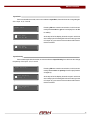
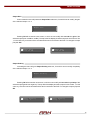
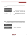
1
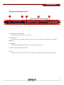
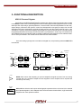
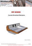
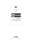
ARK
20 series
USER MANUAL
V.11.02
ARK 20xx processor
Loading DSP Program
ARK
Valencia, Spain
-
www.lynxproaudio.com
INDEX
1.- INTRODUCTION.
ARK Description.... ......................................... .... ... .5
Description of the ARK's front panel ..................................6
Description of the ARK's back panel.................................7
2.- SET UP AND CONNECTION
Connectors and connections............................................8
ARK dimensions ..........................................................8
3.- FUNCTIONAL DESCRIPTION.
Block diagrams ........................................................9
4.- OPERATING INSTRUCTIONS.
Operating procedures .......................................................11
Display and encoder .........................................................12
Program menus ............................................................13
- Open Preset .......................................................13
- Input Gain ......................................................14
- Input Polarity ...............................................14
- Input Delay .................................................15
- Output Route ..................................................15
- Output Gain ....................................................16
- Output Polarity ...............................................16
- Output Delay ...............................................17
- Firmware ..................................................17
5.- SPECIFICATIONS. .........................................................................18
6.- TROUBLESHOOTING. ..........................................................19
7.- GUARANTEE. ........................................................................................20
WELCOME
Just contact the new generation of digital processors ARK, designed and manufactured by Lynx
Pro Audio S.L.
Before working with the processor we recommend that you read this manual, in its pages you will
find instructions for use, programming examples and practical advice that will be of great help. Also
consider reading the Software manual, available separately and easily downloadable from the LYNX
web www.lynxproaudio.com.
For the maximum optimization of any sound system a first class digital processor with different
processing options is required. Thus ARK processors become a working tool of great value, providing
the user with the best solutions in the market with the highest level of accuracy and a host of features for
the professional.
We hope that as a user you will be completely satisfied. We are sure that the ARK processor will
meet your expectations and make it easier for you to get the most out of your system.
IMPORTANT SAFETY INSTRUCTIONSThe CE mark of the processor shows that it is verified and tested to accomplish the
European Norms and International Norms about Electromagnetic Compatibility and Electrical Safety.
Radiated Emissions :
RF Immunity:
Electical Safety:
EN55013-1 (1996)
EN55103-2 (1996)
EN60065 (1993)
IEC65 (1985) and emendation 1, 2 and 3
This product also meets the specifications of the following safety directives:
Low Voltage Directive 73/23/EEC
EMC Directive 89/336/EEC
Product Developed and Manufactured in the European Union.
PRECAUCION
RIESGO DE SHOCK ELECTRICO
NO ABRIR
CAUTION
RISK OF ELECTRIC SHOCK
DO NOT OPEN
The symbols shown above are internationally accepted symbols that warn of potential hazards with
electrical products. The lightning flash with arrowpoint in an equilateral triangle means that there are dangerous
voltages present within the unit. The exclamation point in an equilateral triangle indicates that is necessary
for the user to refer to the owner's manual.
Warning :
Do not expose the processor to humidity and dust.
Do not take off the top cover.
Do not handle internal elements to avoid electrical shock.
Use only power cords in good condition.
Unpacking the ARK .Before unpacking your new processor, verify that the box does not show any damage or deformation.
If this happens, please claim the damage to your fordwarder. Once unpacked and verified its correct operation,
keep the original box in case you need to ship it back to your provider.
4
INTRODUCTION
1.- INTRODUCTION
ARK-20 series offers the user a perfect tool for processing, with three processor models
available (ARK-2024, ARK-2026, ARK-2048) with two or four inputs and eight outputs.
ARK-20 series processors offer a RMS compressor/limiter used to adjust the sound level of
the transducer, keeping the original dynamics while respecting the original transition, getting a better
acoustic result. This Dynamic minimizes distortion levels and provides protection for all acoustic and
electronic components of the system.
With fixed latency of 0.6 ms ARK processors offer one of the lower latencies on the market. All
ARK models offer 120 dB dynamic range and AD-DA converter Cirrus Logic high-performance 24-bit
and 96 KHz. The internal DSP processor works with double precision floating point, reaching a 56-bit
internal resolution, one of the highest resolutions available today on the market. This allows the use of
high-precision filters with very low distortion and providing a quality and unsurpassed sound clarity.
In the security section, different levels of access restrictions are included. That can be
managed by a global password and a preset password, with the choice to select which processing
functions can be modified or not. The front panel can also be blocked, denying any access.
For the available ARK control software, we recommend reading the software manual. The
control software for ARK processors is designed to provide the user with fast and intuitive access to
each process area, facilitating the programming of the processor from a computer. The software
manual is a document available in the downloads section of the website www.lynxproaudio.com
5
INTRODUCTION
ARK20's front panel description-
1
2
3
4
5
1.- POW ER SUPPLY INDICATION.
Indicates that the processor is switched on.
2.- LCD DISPLAY.
24 characters LCD Display. Shows the menus, funtion information, and various user editable
parameters.
3.- ENCODER.
Enconder with pushbutton from which we can modify move into the menu
4.- SIGNAL, LIMITATION AND CLIP LEDS.
5.- USB.
USB connection from the frontal to set parameters or update the firmware via ARK software.
6
INTRODUCTION
ARK20 Back panel description.-
9
6
7
8
10
11
06.- AUDIO INPUTS.
Analog: Balanced signal via female XLR connectors.
07.- AUDIO OUTPUTS.
Analog: Balanced signal via male XLR connectors.
8.- ETHERNET CONNECTOR (OPTIONAL).
Ethercon RJ45 professional connector for a secure connection.
9.- POWER ON SWITCH.
10.- IEC MAIN POWER CONNECTOR .
The power cord is supplied together with the processor. The ARK includes a precise switching power
supply. It withstands power supply from 85 to 264 volts and is continuously self-regulating providing a
perfect functioning even with poorly regulated voltages.
11.- FUSE HOLDER.
1A fuse. (Always replace with equivalent fuses)
7
SETUP
2.- SET UP AND CONNECTION
Connectors and connections.
XLR SOCKET CONECTORES
2
1
INPUTS
1.- GROUND
2.- SIGNAL (+)
3.- SIGNAL (-)
1
2
OUTPUTS
1.- GROUND
2.- SIGNAL (+)
3.- SIGNAL (-)
3
3
OVERHEAD XLR CONNECTORS
To be conected to the processor input
1Ground
2 Sig. (+)
3 Sig. (-)
To be conected to the processor output
1Ground
2Sig. (+)
3Sig. (-)
ARK dimensions (in mm).
45
225
482
8
FUNCTIONAL DESCRIPTION
3.- FUNCTIONAL DESCRIPTION
ARK-20 Process Diagram.
Four floating point DSPs (Digital Signal Processors) with 56 bits of internal resolution are included
in the ARK processor. All this calculating power is used in the signal processing algorithms which control
all the process: input delays, global equalisation, crossover filters, individual equalisation for each way,
output delays, protections and dynamic control and independent noise gate per output. All of these
algorithms have been developed to provide the best precision and the lowest round-off noise in the
calculations. This way, the best sound fidelity and transparency free of noise is achieved. The wide internal
range (56 bit) allows the use of high-precision filters with very low distortion. Cirrus Logic converters 24-bit
and 120 dB dynamic range assures a clean sound without distortion and background noise makes the ARK20 one of the processors in the market with the best technical characteristics.
Once the analog input signal is converted into a digital one, the processing inside the ARK DSPs
is as follows:
OUTPUTS
ROUTER
GAIN
29 Band
GEQ
PEQ
GAIN
DELAY
RMS
DYNAMIC
OUTPUT1
RMS
DYNAMIC
OUTPUT8
A
:
D
INPUTS
INPUT A
CROSSOVER
DELAY
A
GAIN
29 Band
GEQ
DELAY
D
INPUT D
ROUTER
A
:
D
CROSSOVER
PEQ
GAIN
DELAY
GAIN
GAIN: Gain control. Gain adjusting in inputs to adapt/fit the signal level sent from the mixing
console and in the outputs to adjust the level supplied to each amplifier and to equalize the
sensitivity in each way.
29 Band
GEQ
GEQ: ARK-20 offers for each input a 29-band graphic equalizer with two choices of Q, the classical
and a special algorithm, which adapts the Q in terms of how are the other filters, to get a smoother
response and more optimal acoustics.
9
FUNCTIONAL DESCRIPTION
DELAY
PEQ
CROSSOVER
RMS
DYNAMIC
DELAY: Configurable delay. In the inputs A-B up to 54 msec, for covering a distance up to 18 m It
is mainly useful when working with important PA equipment covering a large distance with
reinforcement blocs. It allows 20 msec at outputs, which correspond to 7 meters approximately.
Thanks to that function, it is possible to rectify the cabinet’s position (alignment) in a multi-way
equipment and avoid cancelling problems due to phase cancellation effects.
PEQ: Output equalisation. There are 9 filters completely configurable per output. These filters
can be parametric, 6dB/oct. and 12dB/oct. low frequencies Shelving (with or without Q), 6dB/oct.
and 12dB/oct. high frequency Shelving (with or without Q), 12 dB/oct. highpass and lowpass,
bandpass, reject band and first and second order Allpass filters. Its aim is to provide a final
equalisation on each way of the equipment.
CROSSOVER: Bands separating filters. Different filters are available: Linkwitz-Riley, Butterworth
and Bessel up to 48 dB/oct. It is also possible to put them in By-pass without affecting the
corresponding way to have full bandwith output.
DYNAMIC: Dynamic section. The ARK-20 offers a sophisticated RMS compressor-limiter on
each output. Limiters and compressors are C.R.I. type (Continuous Increment Ratio) for low
distortion.
Using a RMS detector for a high-quality compression. The system will reach its maximum
power gradually and the sound is perfectly crisp and clear at all times, avoiding the usual problems
of normal limiters. Also available is a noise gate that will respond with the same timing as the
RMS dynamics and you can select different thresholds of noise to remove.
On the ARK front can see when a via is limiting because LIMIT LED lights.
10
OPERATING INSTRUCTIONS
4.- OPERATING INSTRUCTIONS.
How to proceed.-
a.- Before switching on the processor:
ARK includes a precise switching power supply. That means that it can adapt itself to any input
supply voltage from 84 and 264 volts and frequencies from 50 to 400 Hz. This is the reason why the processor
is guaranteed to work perfectly under any voltage and the final sound quality is completely independent of
the supply voltage or the kind of generator used. Nevertheless it is recommended to check the supply
voltage before working to avoid any possible problem when connecting at 380 volts. A fuse holder is included
in the ARK processor with a spare fuse (1 A) situated in the IEC connector input of the power supply
connector.
It is recommended to turn off the volume of all the power amplifiers down to 0 before switching on
the processor. We will then be able to check whether any of the 4 processor outputs are connected to their
corresponding power cabinets, avoiding any irretrievable damage in the loudspeakers (specially in
expensive high frequencies drivers).
In any installation, it is suitable to place audio and lighting systems in independent power lines to
protect both parts separately and to avoid interferences between the different equipments.
b.– Once the processor is ON:
When switching on the ARK processor, audio outputs remain short-circuited to ground for a few
seconds in order to avoid the dangerous start up transient time necessary for the processor to receive a
stable voltage and to check internal functions such as: good running of the converters, working memory
checking, DSP processors start-up and current configuration loading. Subsequently, if everything is
correct, all the outputs will commutate at the same time introducing audio in each output with a soft-start
(The audio be increased until reaching the value set in the preset).
11
OPERATING INSTRUCTIONS
Display, buttons and encoders.ARK processor comes, for programming all functions, with a 24 characters and two lines LCD display,
as well as an encoder to move into the menu. It is recommended to use the ARK software for better
viewing of EQ curves and ease of programming.
ENCODER DESCRIPTION:
The encoder allow modification of menu items and move us by menus and submenus.
RIGHT:
Increase the number of menu.
LEFT:
Decrease the number of menu.
PUSH OK: Provides access to menus and submenus and confirm
their actions
12
MENU OPTIONS
Program Menus.ARK Processor has an LCD Display in which there are various configuration menus to store and
modify the operation of processor options and to protect stored data and access to them.
These menus are:
-
Open Preset
Input Gain
Input Polarity
Input Delay
Output Route
Output Polarity
Output Delay
Firmware
When switching the processor, the start menus appears:
Lynx Pro Audio S.L.
ARK-20xx Processor
Lynx Pro Audio S.L.
Loading DSP Program
Load the DSP program.
Lynx Pro Audio S.L.
Calculating Preset
Calculate and send preset data to the present DSP.
1. No Name
Press OK to enter
Initially in the first line shows the memory number and
name of the current program.
Pressing the function OK allows you to enter the detailed
configuration of the functions of the processor.
Open Preset
The Open Preset menu is the first to find when you press OK after the welcome menu.
Open Preset
If we press OK we will select the memory we want to load
using the encoder.
Open Preset
1: No Name
Memory number will be displayed and the name of the preset
selected.
Open Preset
Calculating Preset...
If we accept, the memory will be loaded and the following
screen appears.
13
MENU OPTIONS
Input Gain
If we increase with the ecoder, we move to submenu Input Gain, from which we can change the gain
of the input A, B, C and D.
Input Gain
A Input Gain
Gain:+0.00 dB
.
.
.
Pressing OK we access the next window, in which we can
modify with encoder the gain of each input (from -40 dBu
to +6dBu).
At the top-left of the display shows the Input in which we
are, initially input A.Pressing OK will confirm and go to the
next input. Any movement of the encoders will be sent in
real-time to DSP.
D Input Gain
Gain:+0.00 dB
Input Polarity
If we increase again with the ecoder, we move to submenu Input Polarity, from which we can change
the polarity of the input A, B, C and D.
Input Polarity
Pressing OK we access the next window, in which we can
modify with encoder the polarity of each input (Positive
or negative).
A Input Polarity
Polarity: +
.
.
.
At the top-left of the display shows the Input in which we
are, initially input A.Pressing OK will confirm and go to the
next input. Any movement of the encoders will be sent in
real-time to DSP.
D Input Polarity
Polarity: +
14
MENU OPTIONS
Input Delay
Increasing the menu, we move to submenu Input Delay, from which we can change the delays
for inputs A, B, C, D.
Input Delay
Pressing OK will access the next screen, in which
A Input Delay
Delay: 54.17ms
25^C
18.77m
we can increase or decrease with encoder the delay of
the current input. This will increase from 0 to 54ms (18.77
meters at 25ºC) for inputs A-B.
With push we change to the next input.
Delay in miliseconds
Delay in meters
Output Route
Next submenu is Output ROUTE, from here we can select from where we take the input signal on
every output.
Output Route
Output Route
1 [Out 1]: A
Again we enter the submenu by pressing OK,in which we
choose the desired input signal for the selected output, in
this case OUT 1 takes the signal from input A. We can
choose inputs A, B, C, D as well as mono A+B, C+D (for
inputs A+B and C+D the input gain decrease to -6dB
automaticaly, to compensate the sum of both channels).
We will change the output selection pressing OK.
The processor will show in brackets the name we have
assigned for such outputs with ARK software.
15
MENU OPTIONS
Output Gain
If we increase the menu will pass to the Output Gain submenu, from which we can modify the gain
of the selected output 1 to 8.
Output Gain
Pressing OK will access the next screen, in which we can modify with encoder the gain of the
selected output (from -40 dBu to +6dBu). The top-left of the display shows the output in which we are. The
1, in this case. Any movement of the encoders will be sent in real-time to the DSP. To change the output
just push OK.
1 Output Gain
...
Gain:+0.00 dB
8 Output Gain
Gain:+0.00 dB
Output Polarity
Increasing the menu will go to Output Polarity submenu, from which we can modify the polarity
of the selected output 1 to 8.
Output Polarity
Pressing OK will access the next screen, in which we can modify with encoder the polarity of the
selected output (positive or negative). The top-left of the display shows the output in wich we are. 1, in this
case. Any movement of the encoders will be sent in real-time to the DSP. To change the output just push
OK.
1 Output
Polarity
Polarity: +
...
8 Output
Polarity
Polarity: +
16
MENU OPTIONS
Output Delay
Next submenu to come is the Output Delay, from which we can modify delays in outputs 1, 2, 3,
4, 5, 6, 7 and 8.
Output Delay
1 Output Delay
Delay: 20.83ms
25^C
7.22m
Pressing OK we will access a new screen, in which
we can modify Delay for the selected output with the
encoder. This range will be from 0 to 20.83ms (7.22
meters at 25ºC) for each output.
With encoder Push we confirm and go to the next
Delay in miliseconds
Output.
Delay in meters
Firmware
And the last submenu is the Firmware, from which we can get information about version of the
current firmware and release date.
Firmware
Lynx Pro Audio S.L.
v4.0 May 10 2010
Pressing OK show the information.
17
SPECIFICATIONS
5.- TECHNICAL SPECIFICATIONS.
Input
Impedance:
Connector:
AD converter:
Dynamic Range:
Max. level:
2/4
20 K Ohm Balanced (10 K Ohm unbalanced)
Balanced XLR (pin 2 +)
24 bit-192KHz, 512x Oversampling
120 dB
+19 dBu (balanced).
Outputs 4 / 6 / 8 (ARK-7024 /7044 / 7026 / 7048)
Impedance:
50 Ohm Balanced (25 Ohm unbalanced)
Connector:
Balanced XLR (pin 2 +)
DA converter:
24 bit-192KHz, 512x Oversampling
Dynamic Range: 120 dB
Max. level:
+18 dBu (balanced)
Audio
Frequency Range
THD (%)
DSP Process
Converters
Propagation Delay:
10 Hz – 24 KHz
<0,0018%
Internal resolution with 56 bit double precision in
floating point
24 bit resolution
0.6 miliseconds
Equalisation
Input GEQ
29 GEQ Bands per input
PEQ output
9 per way
PEQ Type filters Parametric, Shelving High, Shelving Low, Low-Pass,
High-Pass, Low-Pass Q variable, High-Pass Q variable,
BandPass, Reject Band, AllPass order 1, AllPass order 2.
Crossover
Linkwitz Riley with 12, 24, 48 dB/oct.
Butterworth and Bessel with 6, 12, 18, 24, 30, 36, 42 and 48 dB/oct.
Noise Gate
1 per Output
Noise Threshold:
-79dBu to -37dBu.
Level Control
Gain
+6dBu to -40 dBu per input / output
Signal Generator
Level
Type:
White noise.
Security Options
Password
Level 0:
Level 1:
Level 2:
0dBu to –40dBu
sin tone from 10Hz to 22KHz, Pink noise,
global
All controls unlocked.
Only permits to change presets.
All frontal controls locked.
Restricted Zones: For each Preset it is
possible to disable the access to any
processor function (EQ, crossover, Limiter,
etc) writing a preset password.
Other functions:
Process Integration with RAINBOW – The acoustical prediction software
Speaker data import from main audio measurement systems.
Export & Import EQ files
Etc.
Front Panel
Display:
Encoders:
Level Meter:
LCD with 24 x 2 characters.
1 with push button.
Input signal, input clip, output signal,output Limiter on
Communication USB
Ethernet (optional).
Delay
Input
Output
54.15 milisec
20.8 milisec for Speaker's alignment
General
Power supply
Consumption
RMS Limiter-Compressor
1 per output.
Threshold:
+18dBu to -50dBu
Compression Ratio:
1:1 to 1:10 (1:infinite with limiter)
Power indication
Shows the maximum power applied to the
speaker for the selected threshold.
85-240 V ~ 40-400 Hz. IEC connector.(Switching power
supply, wide range)
30 W
Operating temperature: -5º to 60º C (23º to 140º F)
Storage temperature: -60º to 75º C (-76º to 167º F)
Humidity: Max. 90% non-condensing
Dimensions
Weight
Warranty
482 x 45 x 226 mm
3 Kg
3 years
18
TROUBLESHOOTING
6.- TROUBLESHOOTING
In this section we try to give solutionsto possible problems :
1 – The processor does not start up:
Check the power supply cord. If it is correctly connected and the red led on the front panel does
not light on, check the fuse situated in the input of the power cord.
2 – The processor starts up but there is no sound:
Check that the processor is being provided with a signal in the correct input, A, B, C or D. If the
signal does reach the processor, the green signal LED will light, otherwise check all the connections from
the mixing console to the processor.
3 – The resulting sound is “strange”:
Check that the 4 outputs and their corresponding cabinets are correctly linked. Always be careful
in increasing little by little the cabinets volume channel by channel in order to check the correct connection
and not to damage the transducers.
4 – One of the cabinets ( with the same signal ) sounds less than the others:
Check that the joining cable from the processor to the cabinet is well balanced otherwise the
output signal will fall 6 dB.
5 – Audio sounds wrong and distorted.
Verify that we are not saturating the input (beyond the 19 dBu input). In this case the LEDs
light up red clip. Sufficient to reduce the input signal to the processor, until no clip LEDs light up. If
this does not work, verify that the signal is not distorted out from the previous gear, for example the
mixer, which could be the gain of that channel very high and saturating the mixer input.
6 – Buttons or encoder do not work.
Verify if there is any keyboard lock activated from the software.
7 – I can not connect by Ethernet.
Check that the USB cable is not connected,it has priority and internally disables the Ethernet
connection. If this is not the case read Annex Ethernet in the software manual.
19
GUARANTEE
7. LYNX PRO AUDIO GUARANTEE
Lynx products are guaranteed against every kind of manufacturing fault 2 year after the date of sale. When products
are under guarantee, the repairing and the free supplying of the device parts in order to correct any kind of defect are
guaranteed by Lynx Pro Audio S.L. In the case that the product could not be returned to the factory for checking and
repairing, Lynx Pro Audio S.L. would supply all the necessary parts.
Lynx Pro Audio S.L. is not responsible for any damage or defect caused during the transport or caused by an undue
or improper handling y a non-authorized person during the life of this guarantee.
All our products undergo rigorous tests and quality controls. We guarantee the characteristics described here within
and their quality against any fabrication defect.
The user loses all warranty rights if he incorporates or carries out any modification to the product, if he uses it outside
of the stated safe working loads or does not secure the system properly using all the pins in their corresponding holes.
For any question regarding the product, the user must quote the model and serial number.
20