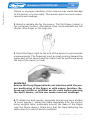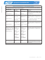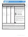
1
SPIROMETER
DATOSPIR 600
USER’S MANUAL
511-900-MU2 • Rev 2.02 • 2013-10
Spirometer DATOSPIR 600
3
1. INSTRUCTIONS FOR USE AND INSTALLATION
1.1.INTRODUCTION
1.2.PREVIEW
1.3. DISTRIBUTION OF CONTROLS, INDICATORS AND
CONNECTORS
1.3.1. FRONT PANEL
1.3.2. RIGHT AND LEFT SIDE
1.3.3. BACK PANEL
1.3.4. STANDARD ACCESSORIES
1.3.5. OPTIONAL ACCESSORIES (according to model)
1.4. INSTALLATION AND SETUP
1.4.1.INSTALLATION
1.5.PULSIOXIMETER
1.6.CALIBRATION
1.7. UPDATING THE DEVICE SOFTWARE
1.8. TECHNICAL SUPPORT
2. TECHNICAL SPECIFICATIONS
2.1. SOFTWARE COMPATIBILITY
2.2. TYPES OF TESTS, FUNCTIONS AND SPIROMETRIC
PARAMETERS
2.3. MEASUREMENT SYSTEM
2.4. ANALYSIS CRITERIA
2.5. ELECTRONIC WEATHER STATION
2.6. MAXIMA PRESSURE MODULE
2.7. PULSEOXIMETER MODULE
2.8. GENERAL DATA
2.9.SIMBOLOGY
3. FUNCTIONING PRINCIPLES
4. SPIROMETRY TECHNIQUE
5. PRESERVATION, PREVENTIVE AND CORRECTIVE MAINTENANCE
6. MODIFICATIONS
ANNEX 1. ELECTROMAGNETIC COMPATIBILITY
511-900-MU2 • REV. 2.02
Contents
CONTENTS
Revised
Date: 2013-10
Revised
Date: 2013-10
Antoni Picó
Technical Manager
Carlos Recio
Sales Manager
0318
IN ACCORDANCE WITH
93/42/EEC Medical Devices Directive
II a Class
SIBEL S.A.
Rosselló 500, 08026 Barcelona - Spain
Ventas Nacionales:
Tel. 93 436 00 08 - email: comercial@sibelmed.com
Ventas Internacionales / International Sales:
Tel. +34 93 436 00 07 - email: export@sibelmed.com
Servicio Técnico / Technical service:
Tel. +34 93 433 54 50 - email: sat@sibelmed.com
Fax : +34 93 436 16 11 - Web: www.sibelmed.com
Spirometer DATOSPIR 600
5
Safety
SAFETY
SPECIAL PRECAUTIONS
The spirometer DATOSPIR-600 has been designed to have the
maximum safety. All the operation instructions must be read
before starting the DATOSPIR-600. Otherwise, injures to the
user or the patient and damage to the device and/or accessories
might occur.
INTENDED USE
The spirometer measures and calculates a long list of human
respiratory function parameters.
The spirometer is not designed to be used in open air conditions,
or under any other conditions or energy supply not foreseen in
this manual.
The spirometer is not intended to be used in moving transport
vehicles. It is adviseble to use the device in an acoustic environment enough silent to allow the patient make the manouvers
correctly and hear the acoustic warnings.
The device must be located in a safety position. This avoids it
falls down and consequently any failure to the device or damage
to patient and/or user.
USER PROFILE
The spirometer is designed to be used by medical staff only,
being supervised by a physician. Specific training in spirometry
is recommended.
Bronchoconstriction test must be performed and supervised by
qualified staff.
User must be familiarized with the functioning of the device before beginning to perform tests with patients.
All necessary information can be found in the user’s manual.
511-900-MU2 • REV. 2.02
Safety
Spirometer DATOSPIR 600
6
For more information, consult SIBEL S.A or your regular distributor.
PATIENT’S EFFECTS IN THE SPIROMETER USAGE
Spirometry tests require the patient’s collaboration, the patient
must perform a complete forced expiration to be able to get
meaningful FVC values. The doctor should assess the patient’s
capacity to perform the spirometry tests.
Special precaution must be taken with children, elderly people
and disabled people.
LIMITATIONS IN USE. CONTRAINDICATIONS
An spirometry test results analysis is not enough for itself to
carry out an accurate diagnosis on the patient’s clinical condition, therefore it must be completed with the clinical history and
those tests the doctor considers necessary.
The tests interpretation and the derived treatments must be
performed by a doctor.
The patient’s symptoms before the execution of any spirometry
test must be considered by health care personnel.
Health care personnel is responsible of the acceptability of a
test.
The spirometer must not be used when results validity might be
probably compromised due to external factors.
Take care NOT to place the equipment where it could be splashed by water or other liquids or cover it with objects that prevent air from circulating around it while it is running.
The device should NOT be used stacked or adjacent to other
equipment.
The equipment must be stored and used within the temperature, pressure and humidity ranges specified in this manual.
511-900-MU2 • REV. 2.02
Spirometer DATOSPIR 600
7
DO NOT alter the integrity of the system earth connection.
The protection against electrical hazards is provided by the
chassis connection to the safety earth. The safety earth connection is only effective when the power supply cable of three
wires provided with the device is plugged to an electrical socket properly connected to earth.
DO NOT remove the device or accessories cover. Servicing
and repair of the apparatus must only be carried out by trained personnel. Contact with the voltage inside the system can
cause serious injury.
DO NOT use damaged transducers, accessories or cables.
DO NOT submerge the device parts in any liquid. IT CAN RESULT IN ELECTRICAL DISCHARGE.
DO NOT use multiple mains sockets, unless they comply with
EN-60601-1. They can degrade electrical safety.
ELECTRICAL DISCHARGE
To ensure vital safety features under the EN 60601.1 standard,
only equipment compliant with the electrical safety standards
in force may be connected to this device. To connect DATOSPIR 600 to a non-medical device with ground conductor, you
must install an additional ground conductor to the non medical
device.
EXPLOSION RISKS
DO NOT uses the device in presence of anaesthetics or flammable gases. IT CAN RESULT IN EXPLOSION.
RISKS OF CONTAMINATION
Fleisch and Turbine Transducers: To avoid risks of contamination
or crossed infection, the turbine and the Fleisch neumotacho511-900-MU2 • REV. 2.02
Safety
ELECTRICAL RISKS
Safety
Spirometer DATOSPIR 600
8
meter must be disinfected following this manual’s instructions
and its mouthpieces must not be reutilized.
Disposable Transducers: It must not be reutilized, each new one
must be used for each new patient.
The use of mouthpieces or any other consumibles of the product
manufactured with improper materials that can compromise
their biocompatibility must be avoided.
RISK OF INTERFERENCE
This is an electronic product, so high frequency emissions can
interfere with the correct use. For this reason, the products
which can generate interferences (radios, cellular phones, etc.)
should be kept apart.
The portable or mobile radiofrequency devices can affect the
normal functioning of the electronic medical devices.
This is a medical electronic device and as such it needs special
precautions regarding the electromagnetic compatibility (EMC)
and it should be installed and setup according to the EMC information attached (See Appendix 1. ELECTROMAGNETIC COMPATIBILITY).
The use of transducers, accessories and cables different to the
ones specified here, except the transducers and cables sold by
the manufacturer as spare parts, could adversely affect patient
safety, cause a malfunction of the equipment and/or produce an
increase of the emissions or a decrease in the device immunity.
REMOVAL OF WASTE FROM ELECTRICAL AND ELECTRONIC APPLIANCES BY DOMESTIC USERS IN THE
EUROPEAN UNION
This symbol on the product indicates that you cannot dispose of the product with domestic waste.
511-900-MU2 • REV. 2.02
Spirometer DATOSPIR 600
9
511-900-MU2 • REV. 2.02
Safety
However, any removal of this type of waste is the responsibility of the user and must be taken to a designated collection
point for the recycling of electrical and electronic appliances.
The separate recycling and collection of this waste at the time
of removal will help preserve natural resources and ensure that
recycling protects your health and the environment. Should you
require further information on the places where you can leave
this waste for recycling, contact the local authorities in your
town or city, the domestic waste management service or the
distributor who sold you the product.
Instructions
Spirometer DATOSPIR 600
10
1. INSTRUCTIONS FOR USE AND
INSTALLATION
1.1. INTRODUCTION
The spirometer DATOSPIR-600 is a compact device held in a
platform type C. It has different types of transducers (Fleisch,
turbine and /or disposable). It can include a module for measuring the Inspiratory and Espiratory Maximal Pressures (MIPMEP or PIM-PEM), and other module for Pulseoximetry measurements (SpO2). The system of data acquisition and transfer is
controlled by a microprocessor. In the PC platform a powerful
software is installed, which controls, analyses, stores and displays the spirometric signals. It works under Microsoft Windows.
It enables, among other functions:
The management of different Data Bases
The performance of FVC, VC, MVV and Postbronchodilation
tests
The graphic presentation in F/V and V/T modes
The selection of different Reference Parameters
The selection of different diagnosis types
The printing of different reports
The presentation of graphics for motivated tests with children
The spirometer DATOSPIR-600 has been developed by the department of R+D of SIBEL, S.A. in collaboration with Laboratory of Pulmonar Function in the Hospital de la Santa
Creu i Sant Pau of Barcelona according to the Quality Manual
of Sibel S.A. and in concordance with the quality standards EN
46001 and ISO 9001, as well as the European Medical Device Directive 93/42/EEC. According to this directive, it is
considered as a product of class IIa.
It also meets the norms of Electric Safety of the product
EN60601.1, IEC 601.1, and the Electromagnetic Compatibility
Standards EN 60601.1.2. View annex Electromagnetic Compatibility.
511-900-MU2 • REV. 2.02
Spirometer DATOSPIR 600
11
This User´s Manual is oriented to all the models and options which can form the spirometer DATOSPIR-600. For
each case, only the options or functions for each model
will be applied.
The series of spirometer DATOSPIR-600 consists of three different models, depending on the options included:
DATOSPIR-600 F
DATOSPIR-600 T
DATOSPIR-600 D
The enclosed table shows the basic characteristics for each model, standard (X) and other optional parts or functions (O).
A model can be transformed into a superior one, by adding the
corresponding parts. In that case, consult the Commercial Department of Sibel, S.A., or your distributor.
OPTIONS
DATOSPIR-600
F
T
D
Transducer FLEISCH..................................... X
O O
Transducer TURBINA ...................................O
X O
DESECHABLE Transducer..............................O
O X
FVC, VC and MVV tests in PRE and
POSTbronchodilation mode ......................... X
X X
Bronchoconstriction Test ............................. X
X X
Graphics superposition ................................ X
X X
Auto-check program .................................... X
X X
Graphic incentive for children . ................... X
X X
Setup program ............................................ X
X
X
Data Bases................................................... X
X
X
Printing with external printer....................... X
X
X
Transfer via INTERNET through PC of
Patients Tests . ........................................ X
X
X
Device check-up....................................... X
X
X
Software update ...................................... X
X
X
Calibration Program .................................... X
X
X
Export of tests to other systems . ................ X
X
X
Module of electronic weather station . ......... O O
O
Module of SpO2............................................ OOO
511-900-MU2 • REV. 2.02
Instructions
1.2. PREVIEW
Instructions
Spirometer DATOSPIR 600
12
Module of PIM-PEM...................................... O
O
O
This product is manufactured under strict quality controls. Nevertheless, accidents may
1-3
happen in the transport or storage, so it is convenient to make
a status check before
installing it, as well as of its accessories
511-900-MU2 • REV. 2.02
Spirometer DATOSPIR 600
13
USER’S MANUAL
511-900-MU2 • Rev 2.02 • 2013-10
511-900-MU2 • REV. 2.02
Instructions
SPIROMETER
DATOSPIR 600
14
Instructions
Spirometer DATOSPIR 600
511-900-MU2 • REV. 2.02
Spirometer DATOSPIR 600
15
SIBEL S.A. is responsible for the safety, reliability and functioning of this device only if:
- The place where the device is and the computer where
the software is installed meets the requirements related
to electrical installation IEC (UNE) for medical devices,
as well as the other applicable norms.
- The repairs, checks or modifications, in or out the warranty period, are performed by technical staff at SIBEL
S.A.
- The use of the software and the recommendations of
use are made by qualified staff, according to the User’s
Manual.
511-900-MU2 • REV. 2.02
Instructions
RESPONSABILITY OF THE MANUFACTURER
Instructions
Spirometer DATOSPIR 600
16
1.3. DISTRIBUTION OF CONTROLS, INDICATORS AND
CONNECTORS
1.3.1. FRONT PANNEL
No.1
Functioning signal pilot.
1.3.2. RIGHT AND LEFT SIDE
No.2
Connection of spirometric transducer
No.3
Connection of pulse oximetry sensor SpO2
No.4
Connection of the Maximal Respiratory Pressures transducer
MIP-MEP
No.5
Board of characteristics
511-900-MU2 • REV. 2.02
Spirometer DATOSPIR 600
17
Instructions
1.3.3. BACK PANNEL
No. 6
Serial communications port
No. 7
Connection of mains supply
No. 8
Additional Earth connection
No. 9
Housing for the Electronic Weather Station
511-900-MU2 • REV. 2.02
18
Instructions
Spirometer DATOSPIR 600
1.3.4. STANDARD ACCESSORIES
No. 10
Disposable mouthpiece
No. 11
Nose clip
No. 12
User´s Manual
No. 13
Mains supply
No. 14
Neumotachometer type Fleisch with holder
No. 15
Transducer with turbine
No. 16
Cable for data interconnection between DATOSPIR 600 and PC
No. 17
Disposable transducer
1.3.5. OPTIONAL ACCESSORIES (depending on model)
No. 18
Accessories option MIP-MEP
No. 19
Accessories option pulse oximetry SpO2
No. 20
Disposable transducer with holder
No. 21
Transport bag
No. 22
Calibration syringe
511-900-MU2 • REV. 2.02
Spirometer DATOSPIR 600
19
Instructions
1.4. INSTALLATION AND SETUP
1.4.1. INSTALLATION
The spirometer DATOSPIR-600 belongs to CLASS IIa, according to the criteria of Medical Products European Directive
93/42/CEE, and according to the type of protection against
electrical shock hazard, the norm EN60601.1, the classification
for the device is CLASS I type B.
The spirometer DATOSPIR-600 works as standard through an
external power supply connected to a main electrical supply of
511-900-MU2 • REV. 2.02
Instructions
Spirometer DATOSPIR 600
20
200 to 240 V 50/60 Hz with earth connection (under demand
of 100 to 130 V 50/60 Hz)
The link of data between the device and the computer is optically isolated.
The computer connected to the device must meet the requirements of electric safety for this type of devices (IEC950,
EN60601, etc.)
The maximum power required (including the calefactor of the
neumotachometer Fleisch) is under 25 VA.
The environment conditions for properly operation are:
-Temperature 10º to 40ºC. (The American Thoracic Society
recommends 17º to 40ºC)
-Humidity lower than 85% (without condensation)
-Atmospheric pressure from 525 to 800 mmHg (from 3000 to
-400 metres approx.)
The power supply cable includes the protection conductor, as
the spirometer has to be connected to the ground, like every
electromedical device of the CLASS I, according to EN60601.1.
Do not place the device close to water or other liquid sources.
Do not cover the device with objects which can prevent the air
circulation during its functioning.
The sequence of operations to setup the DATOSPIR-600 in
connection with the PC is the following:
1 Connect the power supply output to the connection no.7
2 Put the power supply switch in position 0 “OFF”
3 Connect the power supply to the mains according to its voltage and frequency, as specified in the power supply, and set the
switch in position “I” START (Light on). Then the DATOSPIR 600
will emit a “beep-beep”.
NOTE: If you have purchased the pulseoximetry module, the
power supply will not have on-off interruptor. It will be only necessary to connect it to the power mains.
4 Connect the transducer to the connector number 2.
511-900-MU2 • REV. 2.02
Spirometer DATOSPIR 600
21
WARNING
The disposables transducers are individually pre-calibrated
and they have and asociated factor. Therefore, there is no need
to carry out any calibration.
The factor must be introduced in the software so far the measurement is performed correctly. Before perform any test, the
check that the factor is the in the plastic bag and in the screen.
The factor can change from one bag to another, but not inside
the same. If you purchase a new lot of disposable transducers,
remember to check and if necessary, update the transducer factor.
If all the indications are fulfilled, the device is ready to be setup.
B.- INSTALLATION OF SPIROMETRY SOFTWARE
For the Software installation in the PC hard disk, follow the SPIROMETRY SOFTWARE SIBELMED W-20 USER’S MANUAL.
511-900-MU2 • REV. 2.02
Instructions
5 Insert the mouthpiece in the transducer (turbine or fleisch
transducer), or o disposable transducer in the disposable transducer handle.
Instructions
Spirometer DATOSPIR 600
22
1.5.1 PULSIOXIMETRY
1.5.1 SAFETY
INTENDED USE
This oximetry sensor should be used by a physician or under the
supervision of medical staff.
The pulse oximeter does NOT require calibration.
The pulse oximeter has NO physiological alarms.
Pulse oximeter probes do NOT allow temporary immersion.
The pulse oximeter waveform is NOT normalizzed.
Patient movements or excessive lighting can affect the accuracy
of the device.
The pulse oximetry module has CE marking and can not reach
temperatures> 42 º.
The oxygen saturation and heart rate measures must be performed using the sensors manufactured by MEDIAID: POX
050-105S (clip) and POX050-820s (Flexible), which have been
validated clinically. Otherwise, there may be significant measurement errors.
These pulse oximetry probes have been validated for the M15
module from MEDIAID.
The wavelengths used are 660 nm (red) and 910 nm (infrared)
and the optical power is about 9.6mW.
Consult the instructions for use of the probes, before use. Follow strictly manufacturer’s safety instructions, as well as those
specified in this manual.
See instructions for use of the sensor to evaluate the toxicity of
SpO2 sensor.
511-900-MU2 • REV. 2.02
Spirometer DATOSPIR 600
23
For log term monitoring, is recommended to use flexible or disposable sensors.
The adult sensor is intended for use on people over 12 years
old. The peadiatric probe is for children between 3 and 12 years.
Although, the adults probes can be used on any pediatric patient
whose fingertip reaches the finger stop of the sensor and on
whom the sensor fits securely.
The system can measure pulse and functional oxygen saturation. A functional meter can not be used to evaluate the accuracy of pulse oximeter probe or a pulse oximeter monitor.
DEGREE OF PROTECTION AGAINST LIQUIDS
Degree of protection against harmful ingress of water. Dripproof IPX1
1.5.2 PULSEOXIMETRY TEST PROCEDURE
WARNING
Use only the oximetry sensor supplied by the DATOSPIR 110/120 spirometer manufacturer. If you use nonvalidated sensors with this equipment, that may cause
significant measurement errors.
1 Plug the pulse oximetry sensor supplied into the no.8 jack on
the device.
WARNINGS
Do not twist unnecessary or use excessive force when
using, connecting, disconnecting or storing the finger
sensor.
511-900-MU2 • REV. 2.02
Instructions
The maximum recommended application’s time of an oximeter,
in the same place, is 8 hours. The point of placement must be
reviewed frequently to determine the position, the movement
and the skin sensitivity of the patient. The reaction to the sensors by the patients may be different depending on their health
and skin conditions. No adhesive material should be used if the
patient has an allergic reaction to it.
Instructions
Spirometer DATOSPIR 600
24
Misuse or improper handling of the sensors may cause damage
to the sensor or to the cable. This would cause incorrect measurements and readings.
2 Select a suitable site for the sensor. The first finger (index) is
the preferred location. Alternative sites recommended are the
thumb, little finger or the large toe.
3 Insert the finger right to the end of the sensor to get accurate
measurements. The fingernail must be kept pointing toward the
upper part of the sensor and the cable must be positioned along
the top of the hand (or food).
WARNING
Ensure that long fingernails do not interfere with the proper positioning of the finger or with sensor function. Remove nail polish or artificial acrylic nails before placying
the SpO2 sensor, as this can cause incorrect readings.
4 To obtain the best results, especially during long-term studies
(8 hours approx.), fasten the cable separately from the sensor,
using surgical tape; preferably around the base of the finger
(see the figure above). Make sure that the tape fastening the
cable does not restrict blood circulation.
511-900-MU2 • REV. 2.02
Spirometer DATOSPIR 600
25
5 Consulte el ANEXO 1 del manual de uso del software W-20 de
espirometría para realizar las pruebas de PULSIOXIMETRÍA con
dicho programa.
1.6. PROCEDURE FOR PERFORMING THE CALIBRATION
For the calibration procedure, follow the SPIROMETRY SOFTWARE SIBELMED W-20 USER’S MANUAL ( 1.14. PROCEDURE FOR PERFORMING THE CALIBRATION )
1.7. UPDATING THE DEVICE SOFTWARE
For the update the internal software, follow the SPIROMETRY
SOFTWARE SIBELMED W- 20 USER’S MANUAL (1.15. UPGRADING THE W-20 APPLICATION AND INTERNAL SOFTWARE FOR THE DATOSPIR-600)
1.8. TECHNICAL SUPPORT
If any problem, doubt, suggestion arises before, during or after
the use of the device, it is recommended to follow these steps:
1. Use the helps available in the program
2. Consult the Use Manual
3. Contact with the After Sales Service of SIBEL S.
SIBEL S.A.
Rosselló, 500
08026- BARCELONA (SPAIN)
AFTER SALES SERVICE
Tel. +34 93 433 54 50
FAX +34 93 436 16 11
e-mail : sat@sibelmed.es
511-900-MU2 • REV. 2.02
Instructions
WARNING
For log term monitoring, is recommended to use flexible
or disposable sensors.
Instructions
Spirometer DATOSPIR 600
26
2. TECHNICAL SPECIFICATIONS
2.1. SOFTWARE COMPATIBILITY
- Windows 95/98
- Windows 2000/NT/XP
- Windows 7
2.2. TYPES OF TESTS, FUNCTIONS AND SPIROMETRIC
PARAMETERS
2.2.1. FORCED VITAL CAPACITY FVC
- Parameters::
* FVC (l) Forced Vital Capacity
* FEV.5(l)Forced Espiratory Volume in 0.5 seconds
* FEV1 (l) Idem in 1 second
* FEV3 (l) Idem in 3 seconds
* FEV.5/FVC (%) Relation
* FEV1/FVC (%) Relation
* FEV3/FVC (%) Relation
* FEV1/VC (%) Relation
* PEF (l/s) Peak Espiratory Flow
* MEF75% (l/s) Maximal Espiratory Flow when the lung still
has the 75% of FVC
* MEF50% (l/s) Idem, at 50% of FVC
* MEF25% (l/s) Idem, at 25% of FVC
* FEF25-75%(l/s) Forced mesoespiratory Flow
* FEF75-85%(l/s) Medium Flow between 75-85% of FVC
* FET25-75 (s) Time passed between 25-75% of FVC
* FET100 (s) Forced Espiratory Time
* MEF50/MIF50(-) Relation
* FEV1/FEV.5(-) Relation
* FEV1/PEF (%) Relation
* MIF50% (l/s) Maximal Inspiratory Flow when 50% of FVC
has been inspired
* FIVC (l) Forced Inspiratory Vital Capacity
* FIV1 (l) Forced Inspiratory Volume in 1 second
* FIV1/FIVC (%) Relation
* FEV1/FIV1 (%) Relation
* PIF (l/s) Peak Inspiratory Flow
511-900-MU2 • REV. 2.02
Spirometer DATOSPIR 600
27
* Edad del pulmón Según la referencia de Morris.
- Diagnosis
* Miller
* Snider, Kory & Lyons
- Reference Parameters
* SEPAR
* CECA
* KNUDSON
* GRAPO
* ZAPLETAL
* MORRIS
* AUSTRIACAS
* GUTIERREZ (CHILE)
* BRASILEÑAS
* POLGAR-WENG
* HATKINSON
* PEREZ PADILLA (MEJICO)
* Otras opcionales
- Ethnic Factor for Reference values
- Patient Identification Data
- Environmental Data: temperature, pressure and relative humidity
- Graphics in FLOW/VOLUME and VOLUME/TIME mode
- Graphics for motivation in paediatric tests
- Concordance Manoeuvre Warnings with the ATS criteria
511-900-MU2 • REV. 2.02
Instructions
* MTT (s) Measured Transit Time
* PEF/PIF (-) Relation
* Vext (%) Extrapolated Volume related to FVC
* MVVin (l/min) Maximal Voluntary Ventilation indirect (30 x FEV1)
* FEV6 (l) Forced Inspiratory Volume in 6 seconds
* FEV1/FEV6(%) Relation
2-2
* Indice EOPC(%) Riesgo de contraer enfermedad de obstrucción de las vías aéreas en los próximos 10 años.
Instructions
Spirometer DATOSPIR 600
28
2.2.2. SLOW VITAL CAPACITY
- Parameters
* VC (l)
* TV (l)
* ERV (l)
* IRV (l) * IC (l) * Ti (s) * Te (s) * Tt (s) * Ti/Tt (-) Slow Vital Capacity
Tidal Volume
Espiratory Reserve Volume
Inspiratory Reserve Volume
Inspiratory Capacity
Inspiratory Time
Espiratory Time
Total Time
Relation
- Normalized Reference Parameters to be selected among different standards
- Ethnic Factor for Reference values
- Patient Identification Data
- Environmental Data: temperature, pressure and relative humidity
- Graphics in VOLUME/TIME mode
2.2.3. MAXIMAL VOLUNTARY VENTILATION
- Parameters:
* MVV (l/min)
* Br./min (Br/min)
Maximal Voluntary Ventilation
Breathing Frequency of MVV
- Normalized Reference Parameters to be selected among different standards
- Ethnic Factor for Reference values
- Patient Identification Data
- Environmental Data: temperature, pressure and relative humidity
- Graphics in VOLUME/TIME mode
2.2.4. POSTBRONCHODILATION TEST
Same parameters as in FVC
Comparing methods between PRE and POST
. % Average between PRE and POST
. % between REF and POST
511-900-MU2 • REV. 2.02
Spirometer DATOSPIR 600
29
2.2.5. BRONCHOCONSTRICTION TEST
- Parameters
* FVC
(l)
Forced Vital Capacity
* FEV1
(l)
Idem in 1 second
* PEF
(l/s) Peak Espiratory Flow
* FEF25-75%
(l/s) forced mid-espiratory Flow
* All the FVC test parameters can be selected.
- Data of Patient identification
- Environmental data of temperature, pressure and relative humidity
- Continuous or shorter methods
- Deviation Percentage between Basal and solution
- Superposition of graphics in FLOW/VOLUME or VOLUME/TIME
- Chronometer for controlling the steps
- Type of medicine and accumulated dose
- Calculation of PD20 (FEV1) by mathematics adjustment or linear interpolation
- Numeric and graphic (dose/response) data summary on screen
- Link with bronchodilatation test
2.2.6. CALIBRATION
- Calibration Program for dynamic tests with a syringe volume
of 1 to 6 litres.
- Record of the last calibrations.
- Indication of calibration warning, if wanted.
2.2.7. PROGRAM SETUP
The Software Setup can be performed by the user in the following aspects:
. Type of printer
. Parameters, diagnosis, references and others
. Graphics, paediatric motivation and language
. Data Bases
. Communication Links with the Software
511-900-MU2 • REV. 2.02
Instructions
. % between PRE and POST
. Difference between PRE and POST
- Graphics Superposition PRE and POST in the external printer
Instructions
Spirometer DATOSPIR 600
30
2.2.8. DATA BASE
- Possibility to work with different Data Bases
- Storing of espirometric tests in FVC, VC, MVV or Postbronchodilation mode
- Storing of tests
- Creation, deletion, modification in the patient cards
- Fast consult in the base by:
. Record
. Reference
. Surname
- Printing Reports from the data base.
2.3. MEASUREMENT SYSTEM
2.3.1. TRANSDUCER TYPES
- Transducer Fleisch type linearized by software and detachable
for its cleanness and sterilization. Diferential manometer of semiconductor type with internal compensation in temperature.
- Transducer turbine type, volumetric bidirectional of axial type
with turn optoelectronic sensor, detachable for its cleanness and
sterilization. The rotation is performed over zaphir shafts in order to have a high reproductibility and duration.
- Disposable transducer linearized by software and individually calibrated for one-use applications. Diferential manometer of
semiconductor type with internal compensation in temperature.
2.3.2. MEASUREMENT RANGE
Fleisch Turbine Disposable
- Measurement Scale:
Flow (l/s)
0 a ±16 0 a ±16 0 a ± 16
Volume (l)
0 a 10 0 a 10
0 a 10
- Dynamic resistance to the air flow
kPa/l/s
< 0,03 < 0,06
< 0,06
- Measurement Accuracy
Volume (the highest)
3% or 50 ml3% or 50 ml3% or 50 ml
Flow (the highest)
5% or 200 ml5% or 200 ml5% or 200 ml
Temporal accuracy 0,5%
0,5%
0,5%
- Resolution in volume (ml)
< 1
< 6
<3
- Sampling rate (Hz)
100
25
100
511-900-MU2 • REV. 2.02
Spirometer DATOSPIR 600
31
2.4. ANALYSIS CRITERIA
Start espiration FVC
. By the retrograde extrapolation method
Final espiration FVC:
. When the accumulated volume in the last second is lower
than 0.03 litres
Selection of tests FVC
. According to the criteria of maximum addition of FVC+FEV1
or at the operator convenience
Selection of parameters
. FVC and FEV1 of the highest value among the stored tests.
For the rest of parameters in the selected test, the one with
the highest addition is recommended .
Start of espiration in VC and MVV by signal level
Selection of tests and parameters in VC and MVV
. Highest value in VC or MVV
2.5. ELECTRONIC WEATHER STATION
-Temperature from 0 to 50ºC+/-1ºC
-Pressure from 375 to 780 mmHg+/- 5mmHg
-Humidity from 0 to 100% +/- 5%
2.6. MAXIMAL PRESSURES MODULE
2.6.1. PARAMETERS
In both espiratory and inspiratory test, the next values are measured:
* Maximal pressure of the 5 manoeuvres.
* Average of the best 3.
* Standard deviation of the best 3
511-900-MU2 • REV. 2.02
Instructions
- Accumulative Volume Time
. Three curves FVC of maximum 60 seconds each
. Three curves VC of maximum 60 seconds each
. Three curves MVV of maximum 60 seconds each
Instructions
Spirometer DATOSPIR 600
32
2.6.2. RANGES AND MEASUREMENTS
Range of Measurement (cmH2O)0-300
Resolution (cmH2O) 1
Accuracy 3 %
Sample Rate (Hz) 100
2.6.3. CONTROL
- Number of manoeuvres.
Up to 5 manoeuvres for each type can be performed (PEmax and
PImax)
- Duration of the manoeuvres.
The maximum duration is 8 seconds
- Start of Manoeuvre.
When the threshold of 3 cmH2O is surpassed
-End of Manoeuvre.
Variation lower than 1 cmH2O in the last 2 seconds.
-Delay in the calculation of the maximum pressure value.
Selectable in the setup between 0.1 and 4.9 seconds. 1 second
as a default.
- Internal Data Base
The Spirometer shares the internal data base for all test types.
2.7. GENERAL DATA
2.7.1. TESTING AND PARAMETERS
Datorpir 600 allows to perform short and long pulseoximetry
measurements (up to 8 hours).
Following parameters are calculated:
*
*
*
*
*
*
*
*
*
CT90%of the time that SpO2 is below 90%
CT80%of the time that SpO2 is below 80%
CT70%of the time that SpO2 is below 70%
IDH-4desaturation index (>= 4%) per hour
IDH-3desaturation index (>= 3%) per hour
IDH-2desaturation index (>= 2%) per hour
SpO2 MáximaSpO2 maximum value
SpO2 MediaSpO2 mean value
SpO2 MínimaSpO2 standard desviation
511-900-MU2 • REV. 2.02
Spirometer DATOSPIR 600
33
2.7.2 RANGES AND MEASUREMENTS
SpO2(%)
Pulso (BPM)
Measurement range 20 - 100
25 - 250
Resolution
1%
1bpm
Accuracy
70 to 100±2%
25-200 bpm ± 2bpm or
±2% (whichever is
60 to 69±3%greater)
Response
Perfusion rate
Digital Pleth Waveform
<60 Unspecified
200-250 bpm ± 3bpm
8 seconds for 80% of 8 seconds for 80% of
patient
patient
0-20%
Centered at 512, norm is 512 counts peak to peak
2.7.3 CONTROL
Beginning and end of of the maneuver manually executed by
the user.
Only one test is possible until a new patient is introduced.
When data is initialized, it is allowed the beginning of a new
study with the same patient.
2.8. GENERAL DATA
-Applicable standards:
1. Related to the product
MEDICAL DEVICE
93/42/CEE Directive (RD 1591:2009)
511-900-MU2 • REV. 2.02
Instructions
* SpO2Stddesviación estandard de la Saturación
* PR Máximovalor máximo de la frecuencia del pulso
* PR Mediovalor medio de la frecuencia del pulso
* PR Mínimovalor mínimo del pulso
*PR Stddesviación estandard del pulso
*Tiempo Pruebatime of the test (zero values are not taken
into account)
Instructions
Spirometer DATOSPIR 600
34
ELECTRICAL SAFETY
• EN 60601-1: 2006+AC:2010 Seg. medical equipment: Class I
EMC. electromagnetic compability
• EN 60601-1-2:2007+AC:2010 EMC in medical equipment (Not
vital support).
See APPENDIX 1. ELECTROMAGNETIC COMPATIBILITY
Recommendations:
• SERIES ATS / ERS TASK FORCE:
No. 1. Miller MR, Crapo R, Hankinson J, et al. General
considerations for lung function testing. Eur Respir
J 2005, 26:153-161.
No. 2. Miller MR, Hankinson J, Brusasco V, et al.
Standardisation of spirometry. Eur Respir J 2005;
26: 319-338.
No. 3. V. Brusasco, R. Crapo and G. Viegi. Standardisation of
the Measurement of lung volume Eur Respir
J 2005;26:511-522
• Sanchis et al. Regulations for spirometry. No. SEPAR recommendations. 1. Arch Bronconeumol 1989, 25: 132-142)
PULSE OXIMETRY (for devices with oximetry option)
• EN ISO 9919:2009 General requirements for basic safety and
essential performance for medical pulse oximetry
USABILITY AND APTITUDE FOR USE
• EN 60601-1-6:2010 General requirements for safety. Part 1-6.
Collateral standard: Usability
• EN 62366:2008 Application of engineering skills to use medical devices
VIBRATION AND TEMPERATURE
• Series EN 60721:1995 Classification of environmental condi511-900-MU2 • REV. 2.02
Spirometer DATOSPIR 600
35
BIOCOMPATIBILITY
• ISO 10993.1:2009+AC:2010 Biological evaluation of medical
devices. Part 1.
SOFTWARE
• EN 62304:2006+AC:2008 Software for Medical Devices
DOCUMENTATION AND INFORMATION
• EN 1041:2008 Information supplied by the manufacturer of
medical devices
• EN ISO 15223-1:2012 Graphical symbols for use in labeling in
medical devices
2. Related to the manufacturer
QUALITY
• EN ISO 13485:2012+AC:2012 Quality management
systems. Requirements for regulatory purposes.
• EN ISO 9001:2008 quality management. Requirements
• EN ISO 14971:2012 Risk management in medica
equipment
WASTE
• RD 208/2005 Electrical and electronic equipment and waste
management. Transposition of WAEE 2002/96/CE Directive
3. A 3. To be satisfied by the user:
DATA PROTECTION
(Applicable to the W20 Software accompanying the DATOSPIR 600, see specific user’s manual)
• Compliance with LOPD and 95/46/CE Directive
WASTE
• RD 208/2005 Electrical and electronic equipment and waste
511-900-MU2 • REV. 2.02
Instructions
tions
• Series EN 60068:1999 Environmental testing
Instructions
Spirometer DATOSPIR 600
36
management. Transposition of WAEE 2002/96/CE Directive
- Relative Humidity:
.Lower than 75% (without condensation)
-Pressure:
.Between 525 and 800 mmHg (3000 to -400 metres high approximately)
-Temperature:
.Storage temperature between -5 and 70ºC
.Working temperature between 10 and 40ºC
-Power supply:
.Mains 220 V+/- 10% 50/60 Hz (other optional)
-Power:
.Inferior to 25 VA
-Dimensions:
.195 x 165 x60 mm
-Weight:
1 Kg. approximately without accessories.
-Useful life:
. 7 years.
511-900-MU2 • REV. 2.02
Spirometer DATOSPIR 600
37
Instructions
2.9 SIMBOLOGY
SERIAL NUMBER
MANUFACTURER
(The date of manufacture, name and address of
manufacturer)
LIMITATION TEMPERATURE
HUMIDITY TEMPERATURE
PRESSURE TEMPERATURE
DIRECTIONS FOR USE
LOT
EXPIRY DATE
CAUTION
LAND
511-900-MU2 • REV. 2.02
Instructions
Spirometer DATOSPIR 600
38
DISPOSAL OF WASTE ELECTRICAL / ELECTRONIC AGREEMENT TO THE WEE DIRECTIVE
DO NOT REUSE
For devices with pulse oximetry module:
APPLICABLE PART B
SpO2 NO ALARMS
DEGREE OF PROTECTION AGAINST WATER
511-900-MU2 • REV. 2.02
Spirometer DATOSPIR 600
39
The spirometer DATOSPIR 600 is a device of physiological
signal acquisition and information processor which providesthe
signal for the lung function.In order to perform the processing
it is necessary to change the physical into electrical magnitude.
The units which perform this change are the transducers. The
DATOSPIR 600 has three different transducers: a) Turbine, b)
Neumotachometer Fleisch and c) Disposable neumotachometer.
The turbine performs a transduction function in two steps: the
volume to measure passes through the turbine and prints a rotor turn, proportional to that volume. This rotor turn is detected
by the interruption of an infrared beam, which sensor converts
the entering light into an electrical digital signal.
The function of the transduction in the Fleisch and Disposable
neumotachometers is also performed in two steps. The air flow
through the neumotachometer creates a difference of pressure,
which is converted into electric signal through a pressure transducer.
3.1. TURBINE
The turbine is axial, with two startors in a spiral form and the rotor consisting of a flat rectangular piece. The form of the startor
makes the air flow passing through the turbine to acquire a turn,
responsible for the rotor turn. The functioning of the turbine is
based on the theory of Flow Mechanics , specially in the Turbo
machines. In this particular case, the angle turning the rotor
is directly proportional to the flow volume passing through the
turbine and the proportionality constant depends on the turbine
physical form.
3.2. TURBINE TURN DETECTOR
The turbine turn detector consists of three couples of emitter
diode and fotodetector of infrared light (invisible), which conveniently diposed, allow to detect the rotor turn and its direction.
The number of beam interruptions is the same as an accumulated angle of rotor turn, that is, the air volume passing through
511-900-MU2 • REV. 2.02
Instructions
3. FUNCTIONING PRINCIPLES
Instructions
Spirometer DATOSPIR 600
40
the turbine. The photodetector provides an electrical digital signal, which is the same as the light beam interruptions This is
directly acquired by the microprocessor.
3.3. NEUMOTACHOMETER FLEISCH
The neumotachometer Fleisch is based on measuring the pressure drop obtained between the ends of an obstruction, which
allows the air pass in a quasi capillar mode. By applying the
Poiseuille law, the relation between the flow and the pressure is
linear: PRESSURE =ct. x FLOW.
In the neumotachometer Fleisch the obstruction is formed by
multiple capillar tubes. Each tube presents a resistance to the
air pass, which produces a pressure drop in its ends.
The reason for the existence of so many tubes and its small diameter is that the air can pass through the obstruction in laminar
regime. The relation flow-pressure is linear to enable the largest
range of flow,avoiding the turbulence effects.
The flows produced in the forced spirometric tests are clearly
turbulent. It is convenient that the flows became laminar, in order to obtain a correct measurement in the resistive area. This
can be achieved by reducing the maximum the tube diameter.
On the contrary, the norms require that this resistance to the
air pass is under a limit, so that the tests measurements are not
affected.
The best solution implies many little tubes, so that the air flow
is laminar when it passes through each tube. The presence of
so many resistors in parallel makes the total value low enough
so as not to affect the measurement.
In fact, the response of the neumotachometer Fleisch is linear
in the low flows, deriving gradually towards a squared behaviour
in high flows, where the regime is transformed into a turbulent
one. This error is about 2% in flows from 0 to 12 l/s. Nevertheless, two flow linearizers have been included, which reduce
the mentioned error. These devices consist of two metalic mesh
cones, located in each air flow inlet. Furthermore, the software
511-900-MU2 • REV. 2.02
Spirometer DATOSPIR 600
41
In order to prevent the condensation and maintain these linearity characteristics, the neumotachometer heats at a temperature
of about 37ºC.
3.4. DISPOSABLE NEUMOTACHOMETER
The disposable neumotachometer has an obstruction or resistor
to the air flow. In this case, the regime of air inside the neumotachometer is turbulent, for which the relation between flow and
pression is squared and not linear:
Pressure= ct. 1 x FLOW 2+CT. 2 X FLOW
Nevertheless, its simplicity allows the neumotachometer to be
built more economically, or even disposable.
3.5. DIFFERENTIAL MANOMETER
The Fleisch and disposable neumotachometers transform the air
flow into a pressure drop between their ends. The next step is to
transform the pressure drop into an electric signal, and for that
we use a diferential manometer.
The pressure tranducer included in the Fleisch and disposable
neumotachometers DATOSPIR 600 are of the semiconductor
type, with internal compensation in temperature.
3.6. FILTERS AND AMPLIFIERS
The analogue signal emitted by the pressure transducer included in the neumotachometers must be conditioned before being
digitalized and processed. This conditioning consists of a amplifying stage which adapts the dynamic range of the pressure
transducer to the digitalizer range, and a filter stage which removes the parasite signals. This filter limits the measurement
band of the system from 0 to 15Hz.
511-900-MU2 • REV. 2.02
Instructions
includes a compensation of linearization, which improves the
measurement.
Instructions
Spirometer DATOSPIR 600
42
3.7. ANALOGUE/DIGITAL CONVERTER
The analogue /digital converter samples the analogue signal,
when the processor indicates it, and quantifies the analogue
signal of its input (in the case of the pressure transducer). As
a result, it gives a digital word at the output which expresses a
numeric value. The converter used in the DATOSPIR 600 has
12 bits, and then 4096 levels are available for assigning to the
pressure signal. The 2048 superior levels are used for the espiratory flows and the 2048 inferior ones for the inspiratory levels.
Both the resolution and the dynamic range converter used cover
widely the specifications and recommendations of the international organisms.
3.8. MAXIMAL PRESSURES MODULE
The DATOSPIR-600 optionally has an external Module of Maximal Respiratory Pressures. This module is connected to the DATOSPIR through a phone connector.
3.8.1. SIGNAL ACQUISITION
The module of maximal pressures includes basically a pressure
sensor, a differential amplifier and a filter.
The pressure sensor covers the range from 0 to 300 cmH2O.
The output of this sensor is amplified and filtered so that the
analogical signal has the intended range and bandwidth.
Then, this signal is transformed into digital with a A/D converter.
The converter used is the same as the one used in the spirometry. (See section 3.7 of the general manual).
3.8.2. CONTROL PROGRAM
The control program performs the processing of the acquired
signal.
Among the important calculations, we must point out :
-Start and end of the manoeuvre:
511-900-MU2 • REV. 2.02
Spirometer DATOSPIR 600
43
-Order of the manoeuvres:
The manoeuvres are saved in the memory in the same order as
they have been performed.
-Automatic deleting of a remaining manoeuvre:
When the 5 memories are full, and a new manoeuvre is performed, the first manoeuvre is always deleted, if this is not the
best. If the first is the best, then the second one is deleted.
3.9. MICROPROCESSOR
3.9.1. PHYSICAL DESCRIPTION
The microprocessor system consists of a series of electronic devices which store, manage, receive and send pieces of information. It is divided into:
-Program of hardware basic control (BIOS) resident in EPROM
of 32KBytes.
-Spirometry program and device management.Data base for
tests resident on memory FLASH of 1MBytes.
-Memory RAM of 128KBytes for storing the device setup, and
status variables.
-Central Process Unit (CPU).
-Communications controller
3.9.2. PROGRAM
The program for control is developed in assembler language and
C high level language, ensuring a high speed in time control and
structured programming. It is divided into two parts, the bios in
EPROM and the aplication FLASH.
511-900-MU2 • REV. 2.02
Instructions
The start of a manoeuvre is considered when the level of 3
cmH2O is surpassed. The end of the manoeuvre is considered
when there is a pressure variation lower than 1 cmH2O for 2 s.
-Delay for the calculation:
For the calculation of the maximal pressure, to avoid artefacts,
a initial period of time is discarded. This period is set to 1 s as a
default but it can be set up between 0.1 anf 4.9 s.
Instructions
Spirometer DATOSPIR 600
44
3.9.3. MEMORY
The storage capacity of temporal data and the capacity of the
setup is 128 KB in RAM.
3.9.4. CPU
This device manages and executes the process which is codified
in the instructions composing the program. The microcontroller
H8/532 of Hitachi is used as CPU.
3.9.5. CONTROLLERS
They perform the information transference between the CPU
and the rest of devices, like the keyboard, the screen and the
printer. They are included in the printed circuit of the microcontroller, except the interphase of the serial communication channel RS-232 and the screen controller.
3.9.6. QUALITATIVE DESCRIPTION
The control program performs the signal acquisition and its temporal storage. It also makes the communication management
with the PC. In this sense, it translates and executes the command received from the PC.
The spirometry program allows that the spirometry signal
treatment meets the applicable norms, taking into account the
calculations of:
-Identification of the espiration start
The start of the test is determined by surpassing the minimum
level of air flow, approximately 100 ml, although immediately
previous values are not discarded.
-Retrograde extrapolation
The determination of the FVC manoeuvre start is made through
the retrograde extrapolation according to the A.T.S and S.E.P.A.R.
criteria.
-Identification of the espiration end The end of the manoeuvre is
made according to the A.T.S. criteria, that is, when the volume
511-900-MU2 • REV. 2.02
Spirometer DATOSPIR 600
45
-Calibration program
Turbine
The accumulated dirty or possible wear of the turbine transducer could result in an inaccurate measurement. In order to
check that the turbine measures correctly, the system includes a
simple verification procedure based on measuring the known
volume of a calibration syringe.
Neumotachometers
The relation between the pressure and flow drops in the neumotachometers depends on the gas viscosity. This viscosity depends on the weather conditions of temperature, pressure and
humidity. For this reason, it is necessary to calibrate the neumotachometer every day or every time that the weather conditions
change. By analysing the relative importance of each factor, the
most influent one is the temperature, followed by the humidity
degree.
511-900-MU2 • REV. 2.02
Instructions
accumulated in the last second is lower than 30 ml.
Instructions
Spirometer DATOSPIR 600
46
4. SPIROMETRY TECHNIQUE (*)
4.1. PROCEDURE
(*) The following is an extract from “NORMATIVA PARA LA ESPIROMETRIA FORZADA” (FORCED SPIROMETRY REGULATIONS)
SEPAR recommendations, Nº 1.
“Forced spirometry must be performed by the patient sitting
bolt upright, having his nose blocked by nose clips. The technician must lean his hand against the patient’s shoulder to prevent the patient leaning forward during espiration time. The
mouthpiece must be crushproof in order to avoid artefacts caused by the reduction of light, due to bite, during forced espiration. Soft mouthpieces must be shortened in order to increase
its consistency. The spirometry will always involve a minimum of
three forced espiration manoeuvres, and a maximum of eight if
they are not considered suitable. Surpassing this limit will mean
pointless patient tiredness and a loss of time for the technician.”
“For the evaluation of the spirometry performed in decubitus
position, you must bear in mind that the obtained data under
these conditions are approximately 10% lower than the data obtained with the patient sitting. In patients with diaphragmatic or
neuromuscular pathology the difference between both positions
can be 40-60%, which makes the observation a useful piece of
information to evaluate the repercussion of this pathology.”
“When you work with the pneumotachometer, the manoeuvre
can be reduced exclusively to the maximum espiration, in the
position of maximum inspiration. The accuracy of a manoeuvre
will be judged by its start, course and end, by observing the patient and the graphic layout. The start must produce a sudden,
neat defection. The course must draw a concavity curve going
smoothly upwards without any rectification. The end should be
asintotic and not perpendicular or sudden (Volume/time). The
measurement of the espired volume during a forced manoeuvre
is influenced by the selection of its starting point. This requires
to choose a criterion of manoeuvre start and maintain it consistently. The mentioned retrograde extrapolation is the most consistent and accepted method by European and American labo511-900-MU2 • REV. 2.02
Spirometer DATOSPIR 600
47
“In order to achieve a good spirometry, the technician must
make sure that the patient’s effort is maximum, that the start is
correct, and that no caugh or Valsalva manoeuvre due to glottis
closing have been produced. Pay special attention to avoid an
excesively early ending of the espiration, which would be detected at the end of the curve, showing the horizontal base line
too perperdicular. Sometimes, the patient partially blocks the
mouthpiece with his tounge or his false teeth. As an essential
criterion, the two best espirations out of the three best acceptable curves cannot differ more than 200 ml in the FVC or in the
FEV1.
The best effort cannot be determined only by simple inspection of the spirometric curve. Measurements must be checked
in order to determine the maximum values. The independent
selection of FVC and FEV1 sometimes causes a slight increase of
variability, since factors such as learning, fatigue or bronchospasm, induced by the espiration, play a part. It is not necessary
to discard the best FEV1 when the manoeuvre where it comes
from has finished prematurely. On the contrary, the FEF25-75%
is influenced by the vital capacity of the selected curve. Mistaken high values may result if we have selected a manoeuvre
with reduced vital capacity and inferior to the individual’s actual
one. Apparently, the most practical way to carry out its calculation is by choosing the manoeuvre with the maximum Vital
Capacity and the FEV1 whose addition is the maximum among
the three selected ones.
4.2. CALIBRATIONS
“Besides the calibration procedures, incorporated to the unit by
the manufacturer, for a quick checking of the running of circuits
and basic machinery of the pneumotachometer, the unit should
admit check out by means of applying external signals. These
signals must bear the maximum similarity to the biological sign,
for which the instruments have been designed, i.e forced espiration, as well as to the flow magnitude, volumes and times.
511-900-MU2 • REV. 2.02
Instructions
ratories, and the preferred method, unless other methods prove
similar results. The volume extrapolated by this method should
be lower than 5% of the vital capacity, or than 150 ml, without
surpassing any of both criteria.”
Instructions
Spirometer DATOSPIR 600
48
This is not always possible but, at least, some of the biological
signal elements, such as volume and flow, should be reproduced
either together or separately. For this purpose, syringes with a
capacity of several litres provide a suitable signal, and flow generators are good for evaluating the accuracy and errors in the
flow measurament. The so-called explosive descompressor is
one of the most practical calibration machines. It consists of a
chamber of 4 or 5 litres pressured at 1 atmospher, provided with
a sudden opening for the violent expulsion of a volume, which
is identical to the volume inside the chamber. In this way an
individual’s forced espiration can be simulated. By placing suitable resistances with different obstruction rate in the exit tube,
the signal is similar to that of a patient with slight, moderate,
or severe obstruction to air flow. Therefore, it checks both the
volume and the flow measurements. If this cannot be achieved,
you can check the machine operating conditions by means of
using “control individuals”, that is to say, people connected with
the laboratory who are willing to cooperate. They can perform
a correct espirometry easily and with little variability (chart I) in
such a way that they can reproduce their espirometry periodically and compare it to previous data. In this way, errors, that are
necessarily of a large magnitude, can be detected. The espirometry variability prevents the detection of small differences in
volume and flow measurement (see chart I).”
“In normal working conditions, calibration by means of volume
signal provided by a hand syringe must be carried out daily.
The signal provided by the syringe must be produced with different thrusts in order to verify that the flow read-out maintains
a rectilinear response.The machine must integrate the signal
always in the same volume, i.e. the volume provided by the
syringe signal, no matter how sudden the injecting operation
may be,as long as it does not surpasses the upper limit of flow
rank, accurately measured by the machine itself (proximity to
actual value).
The calibration with dynamic gauged signal provided by the explosive decompressor or espirometry measurement in control
individuals, mentioned above, cannot be performed so often. As
for tachometers, it is advisable to carry it out with the decompressor once a fortnight. As espirometries with control individuals are more complicated and less available, it cannot
511-900-MU2 • REV. 2.02
Spirometer DATOSPIR 600
49
“Chart 1.” Variability of the espirometry in a healthy person
Coeficiente de variación (%)
Variables
Age: 6-20 years*
FVC
1.9
Age: 20-70 years**
2.2
FEV 1
2.2
2.2
FEF 25-75%
6.5
4.8
MEF 50%FVC
5.3
4.7
* Values corresponding to 33 healthy volunteers.
** Values of 20 healthy adults.
4.3. REFERENCE VALUES FOR FORCED SPIROMETRY
“SEPAR”
The DATOSPIR-600 spirometer incorporates the tables of reference of the SEPAR, that can be selected by means of the Setup
Program, paragraph 1.8. Next, the equations corresponding to
the SEPAR and ECCS-93 reference values are presented. If you
are interested in some other tables, request it to SIBEL S.A.
511-900-MU2 • REV. 2.02
Instructions
be performed more often than once a month, unless you suspect a malfunction.
Instructions
Spirometer DATOSPIR 600
50
Parameter
Sex
R
SEE
FVC
M
0.02800T + 0.03451P + 0.05728E - 3.21
0.947
0.947
F
0.03049T + 0.02220P + 0.03550E - 3.04
0.935
0.313
FEV1
M
0.02483T + 0.02266P + 0.07148E - 2.91
0.945
0.378
F
0.02866T + 0.01713P + 0.02955E - 2.87
0.940
0.263
*FEV1/FEVC%
M
0.593E - 0.113P +81.60
F
0.026T +82.60
FEF25-75%
M
0.038T + 0.140E - 4.33
0.832
0.796
F
0.046T + 0.051E - 4.30
0.789
0.651
M
0.075T + 0.275E - 9.08
0.907
1.073
F
0.073T + 0.134E - 7.57
0.879
0.831
M
0.017T + 0.157E + 0.029P - 2.17
0.856
0.811
F
0.046T + 0.067E - 4.17
0.803
0.669
M
0.024T + 0.066E - 2.61
0.760
0.562
F
0.027T + 0.032E - 2.68
0.709
0.507
PEF
MEF50%FVC
MEF25%FVC
Ecuation: (6-20 years)
Parameter
Sex
Ecuation: (20-70 years)
R
SEE
FVC
M
0.0678T - 0.0147E - 6.05
0.72
0.530
F
0.0454T - 0.0211E - 2.83
0.75
0.403
FEV1
M
0.0499T - 0.0211E - 3.84
0.75
0.444
F
0.0317T - 0.0250E - 1.23
0.82
0.307
*FEV1/FEVC%
M
- 0.1902E + 85.58
F
- 0.224E - 0.1126P + 94.88
FEF25-75%
M
0.0392T - 0.0430E - 1.16
0.55
1.000
F
0.0230T - 0.0456E + 1.11
0.70
0.680
M
0.0945T - 0.0209E - 5.77
0.47
1.470
F
0.0488T - 0.0304E + 0.35
0.47
1.040
MEF50%FVC
M
0.0517T - 0.0397E - 2.40
0.47
1.300
F
0.0242T - 0.0418E + 1.62
0.56
0.925
MEF25%FVC
M
0.0190T - 0.0356E - 0.14
0.63
0.620
F
0.02T - 0.031E - 0.0062P - 0.21
0.76
0.405
*FEV1/PEF
M
6.64
F
7.77
*FEV1/FEV0.5
M
1.45
F
1.50
M
0.66
F
0.88
M
1.39
F
1.42
M
0.80
F
0.89
PEF
*MEF50/MIF50
*PEF/PIF
*FEV1/FIV1
M: Male; F: Female
R: multiple correlation coefficient
SEE: typical estimation error
T: size (cm); P: weight (Kg); E: age (years).”
The parameters with an asterisk (*) are not related in the reference standard of the SEPAR.
511-900-MU2 • REV. 2.02
Spirometer DATOSPIR 600
51
(Standarized Lung Function Testing, Official Statement of the European Respiratoy Society, Luxembourg 1993)
Parameter
Sex
Ecuation: (18-70 years)
RSD
1.64RSD
FVC
M
5.76H - 0.026A - 4.34
0.61
1.00
F
4.43H - 0.026A - 2.89
0.43
0.71
FEV1
M
4.30H - 0.029A - 2.49
0.51
0.84
F
3.95H - 0.025A - 2.60
0.38
0.62
*FEV1/FEVC%
M
- 0.18A +87.21
7.17
11.80
F
- 0.19A +89.10
6.51
10.70
FEF25-75%
M
1.94H - 0.043A + 2.70
1.04
1.71
F
1.25H - 0.034A + 2.92
0.85
1.40
PEF
M
6.14H - 0.043A + 0.15
1.21
1.99
F
5.50H - 0.030A - 1.11
0.90
1.48
MEF75%FVC
M
5.46H - 0.029A - 0.47
1.71
2.81
F
3.22H - 0.025A + 1.60
1.35
2.22
MEF50%FVC
M
3.79H - 0.031A - 0.35
1.32
2.17
F
2.45H - 0.025A + 1.16
1.10
1.81
MEF25%FVC
M
2.61H - 0.026A - 1.34
0.78
1.28
F
1.05H - 0.025A + 1.11
0.69
1.13
M: Male; F: Female
H: high (m); A: age (years).
RSD: (Residual Standard Deviation)
Between 18 and 25 years, 25 is computed for all references.
IMPORTANT NOTE
A ETHNIC FACTOR can be introduced in the DATOSPIR
-600 Spirometer. This factor modifies the reference values for different population groups. It can be in the range from 75 % to 110 % of the reference values, being a
100 % the value of the tables.
511-900-MU2 • REV. 2.02
Instructions
4.4. REFERENCE VALUES FOR FORCED SPIROMETRY
“ECCS.93”
Instructions
Spirometer DATOSPIR 600
52
4.5. TECHNIQUE OF MEASUREMENT AND REFERENCE
VALUES
The maximal inspiratory pressure (PImax) depends directly on
the strength developed by the inspiratory muscles. Its measurement is very useful in the diagnosis and follow up of patients with
neuro-muscular illnesses, specific alterations of the respiratory
muscles, different processes of the thoracic area, air trapping or
modifications produced by breath depressive medicines, among
other clinic situations The maximal espiratory pressure (PEmax)
also informs about the cough efficacy and the drainage of the
bronchial secretions. In both cases, they are measures easy to
performe and comfortable for the patient. They can be obtained
near the patient and allow to follow his/her evolution.
The procedure to obtain the PImax and the PEmax must complete the following aspects:
- Correct collaboration of the patient to get a maximum effort in
the manoeuvres. The patient must keep his/her hands against
the cheeks and leave them flaccid to attenuate the pressure generated by the facial muscles.
- To measure the PImax, the patient must perform a deep inspiration from the position of Residual Volume and maintain the
effort for at least 3 seconds.
- To measure the PEmax, the patient has to inspire previously up
to the position of Total Pulmonary Capacity and from there blow
with the maximum effort.
- It is advisable a minimum of three satisfactory manoeuvres for
each pressure.
If measuring errors are suspected, we must make sure that there are no leaks in the system and the correct collaboration of the
patient in the maximum effort manoeuvres.
The Module of Maximal Pressures is useful for Pneumology,
Anaesthesiology, ICU and Neurology units, for isolated determinationsor for the follow up of interned patients.
511-900-MU2 • REV. 2.02
Spirometer DATOSPIR 600
53
A-) P MORALES
Presiones respiratorias estáticas máximas en adultos. Valores
de referencia de una población caucasiana mediterránea.
P. Morales, J. Sanchís, P.J. Cordero y J.L. Díez.
ARCHIVOS DE BRONCONEUMOLOGÍA. Vol 33, num 5, 1997.
B-) SH WILSON
Predicted normal values for maximal respiratory pressures in
caucasian adults and children
SH Wilson, NT Cooke, RHT Edwards, SG Spiro.
THORAX 1984; 39:535-538.
C-) BLACK & HYATT
Maximal Respiratory Pressures: Normal values and relationship
to age and sex Black LF, Hyatt RE
AM REV RESPIR DIS. 99:696-702, 1969
D-) MR CHARFI
Les pressions ventilatoires maximales à la bouche chez l’adulte:
valeurs normales et variables explicatives
MR Charfi, R Matran, J Regnard, MO Richard, J Champeau, J
Dall’ava, A Lockhart
REV MAL RESP, 1991, 8, 367-374.
511-900-MU2 • REV. 2.02
Instructions
The device includes 4 different references, to be selected by the
user. Next, the bibliographic reference is detailed.
Instructions
Spirometer DATOSPIR 600
54
5. PRESERVATION, PREVENTIVE AND CORRECTIVE MAINTENANCE
The DATOSPIR 600 requires first of all, as any device, and specially for medical applications, a preservation or maintenance
directed to the safety of the patient, operator and environment,
and secondly, to ensure the reliability and accuracy of the
functions for which it has been developed. All of this means a
series of routines which must be carried out.
5.1. PRESERVATION
Preservation is the action directed to maintain the device in a
correct operation condition, and the person in charge of it does
not require any special technical quality, except for the proper
knowledge of the functions and manipulation of the equipment.
The operations to be carried out are as follows:
5.1.1. CLEANING OF THE NEUMOTACHOMETER OR TURBINE TRANSDUCER
A- Neumotachometer Fleisch
The neumotachometer is the most delicate part of the spirometer, so special care must be taken in its handling.
As the neumotachometer is the part directly exposed to the patient, it is necessary to maintain it in perfect physical and hygienical conditions.To this purpose, proceed as follows:
1 The rubber mouthpieces can be disassembled and the linearizer cones can be taken out, as in the drawing 5.1.
511-900-MU2 • REV. 2.02
Spirometer DATOSPIR 600
55
Instructions
Fig. 5.1.
2 The laminator can be taken out turning to the left and pulling
as in the drawing 5.1.
3 The mouthpieces, cones and laminator can be washed with
soap and water. The procedure must be very careful, due to the
structure of the laminator.
4 Once cleaned, it is convenient to clean it again with distilled
water, in order to avoid the salt sediments, specially in the flow
laminator.
5 The final dry can be made with a simple electri
cal dryer, e.g. a hair dryer, to accelerate the process. Take care
that the laminator does not reach a temperature over 130ºC, so
do not bring the dryer near the laminator for more than 15 or 20
cm and do not maintain it for a long time.
6 The laminator housing and the neumotachometer exterior can
be wiped with a dry cloth, or wet with water, drying afterwards
the rest of humidity, and taking care that no water can enter in
the holes of the pressure inlet or in the transducer interior. See
drawing 5.2.
Do not use abrasive substances or solvents.
511-900-MU2 • REV. 2.02
56
Instructions
Spirometer DATOSPIR 600
Fig. 5.2.
7 Assemble the set again, according to drawing
Fig. 5.3.
.
If a microbian contamination is suspected, it is necessary to use
antiseptics in solution or more complex sterilizing procedures.
PRECAUTION
DO NOT EXPOSE THE TURBINE TO TEMPERATURES EXCEEDING 70º C
B- Transducer type turbine
As the turbine is the part directly exposed to the patient, it is
necessary to maintain it in perfect physical and hygienical conditions. To this purpose, proceed as follows:
511-900-MU2 • REV. 2.02
Spirometer DATOSPIR 600
57
Instructions
Fig. 5.4.
1 The turbine can be disassembled from the device housing by
pressing smoothly to take it off.
2 The turbine can be cleaned with soap and water. Do not use
solvents or alcohol , etc. that can damage the components. Since the reliability of the turbine depends on it, take care so as
not to damage it.
3 Once it is cleaned with clear water, it is convenient to avoid the
salt sediment by clening it again with distilled water.
4 The final dry can be made with air at room temperature.
5 Assemble the turbine in the housing again
Fig. 5.5.
If a microbian contamination is suspected, it is necessary to use
511-900-MU2 • REV. 2.02
Instructions
Spirometer DATOSPIR 600
58
antiseptics in solution or more complex sterilizing procedures,
for example the immersion in a solution of Dietilentramine or
Sodium Dichloroisocianurate for 10 or 30 minutes.
P RECAUTION
DO NOT EXPOSE THE TURBINE AT TEMPERATURES EXCEEDING 60ºC OR BELOW 0ºC. DO NOT USE SOLVENTS,
ALCOHOLS OR SIMILAR SUBSTANCES IT DURING ITS
CLEANING, WHICH CAN DAMAGE IT.
C- Maximal pressure transducer
The shutter probe can be washed with soap or some disinfectant
liquid which does not chemically attack the methacrylate or Teflon of the composition.
After the rinse and drying of the probe, lubricate the friction
space between the probe and the cursor with Vaseline. Finally
check that the components are not obstructed and that it works
correctly.
5.1.2. SPIROMETER
The spirometer is smoothly wiped with a dry or slightly watermoistened cloth, drying thereafter the remanent humidity. Take
care that no liquid penetrates inside or in the connectors or
connections.
Do not use abrasive substances or solvents.
5.2. PREVENTIVE MAINTENANCE
The preventive maintenance consists of all those technical actions directed to keep the device in a good condition of use.
Four types of preventive maintenance are established:
1 The device, by starting, performs a comprobation of some of
its parts.
2 A second type, which can be carried out by the same user,
consists of a periodical supervision of the aspect of the different
511-900-MU2 • REV. 2.02
Spirometer DATOSPIR 600
59
If any anomaly is detected, which the user cannot resolve by
himself, inform the aftersales service of SIBEL S.A. or your
Distributor, so that the y proceed to check or repair it.
3 The user can enter the Maintenance Program to adust and/
or verify some parts of the device, as detailed in paragraph 1.15.
4 The fourth type consists of a general technical verification of
the safety systems, adjustments, functions etc. which configurate the device.
THIS TECHNICAL VERIFICATION WILL BE PERFORMED
WITH ANNUALPERIODICITY, and according to the Verification and Adjustment Procedure of the DATOSPIR 600 available
by the manufacturer. This type of operations must be performed
by qualified technical personnel of the maintenance department
of the centre, technical service of your distributor or the manufacturer.
In any case, SIBEL, S.A., as the manufacturer, must authorize
in writing, at least during the warranty period, the corresponding technical service, allowing them to perform such maintenance. In any case no responsability for damage, misfunction
etc. will be admitted, which might arise as a result of a defective
maintenance by persons not belonging to SIBEL, S.A.
The Spirometry Software DATOSPIR 600 does not require
any specific maintenance, except the one for any computer program which manage information.
-Make a copy in a floppy disk or other supports, in case the original is damaged.
- Make periodical back up copies in the Data Bases used , so as
to restore them if any piece of information is lost in the computer.
511-900-MU2 • REV. 2.02
Instructions
interconnections and other external elements of the device. In
this supervision, you will verify that all the interconnections are
perfectly connected, that all the cables and/or connectors,as
well as other elements, do not present breakages or external
damages.
Instructions
Spirometer DATOSPIR 600
60
-If any problem, doubt or suggestion appear before, during or
after the use of the device, it is recommended to follow these
steps:
1 Use the helps available in the program
2 Consult this User Manual
3 Contact the Aftersales Service of SIBEL S.A.
SIBEL S.A.
Rosselló, 500
08026- BARCELONA (SPAIN)
SERVICIO POSTVENTA
Tel. +34 93 433 54 50
FAX +34 93 436 16 11
e-mail : sat@sibelmed.com
5.3. CORRECTIVE MAINTENANCE
The corrective maintenance consists of keeping the device in a
good condition of use, which has been put out of service due to
bad operation or use, and which is necessary to repair.
In case of detecting in the system a breaak-down which impedes
the normal use, disconnect the device from the power supply
and contact the After Sales Service of SIBEL S.A., specifying as
detailed as possible the type of anomaly detected.
511-900-MU2 • REV. 2.02
Spirometer DATOSPIR 600
61
Instructions
6. MODIFICATIONS
511-900-MU2 • REV. 2.02
Instructions
Spirometer DATOSPIR 600
62
Guidance and manufacturer’s - electromagnetic immunity
The Datospir-600 is intended for use in the electromagnetic environment specified below. The customer or
user should assure that it is used in such environment.
EN-IEC 60601
test level
Compliance level
Electromagnetic environment Guidance
Electrostatic discharge
(ESD)
±6 kV contact
±6 kV contact
EN-IEC 61000-4-2
±8 kV air
±8 kV air
Floors should be wood, concrete or ceramic tile. If floors are covered with synthetic material, the relative humidity should
be at least 30 %.
Immunity test
Electrical fast transient/ ±2 kV for power
Mains power quality should be that of a
±2 kV for power
burst
supply lines
typical commercial or hospital environsupply lines
ment.
EN-IEC 61000-4-4
±1 kV for input/
Not applicable
output lines
Surge
±1 kV in differen- ±1 kV in differen- Mains power quality should be that of a
typical commercial or hospital environtial mode
tial mode
ment.
±2 kV in common ±2 kV in common
mode
mode
EN-IEC 61000-4-5
Voltage dips, short in- <5% Ut
terruptions and volta- (>95% dip in Ut)
ge variations on power for 0.5 cycle
supply input lines
40% Ut
(60% dip in Ut)
EN-IEC 61000-4-11
for 5 cycle
<5% Ut
(>95% dip in Ut)
for 0.5 cycle
Mains power quality should be that of a
typical commercial or hospital environment.
40% Ut
(60% dip in Ut)
for 5 cycle
70% Ut
(30% dip in Ut)
for 25 cycle
70% Ut
(30% dip in Ut)
for 25 cycle
<95% Ut
(>5% dip in Ut)
for 5 seconds
<95% Ut
(>5% dip in Ut)
for 5 seconds
Power frecuency (50 / 3 A/m
60 Hz) magnetic field
The input/output connection cables do
not surpass 3 metres length.
3 A/m
Power frequency magnetic fields should
be at levels characteristic of a typical location in a typical commercial of hospital
environment.
Note Ut is the a.c. mains voltage prior to application of the test level.
511-900-MU2 • REV. 2.02
Spirometer DATOSPIR 600
63
The Datospir-600 is intended for use in the electromagnetic environment specified below. The customer or
user should assure that it is used in such environment.
Immunity test
EN-IEC 60601
Test Level
Compliance
Level
Electromagnetic environment Guidance
Portable and mobile RF communications equipment should be used no closer to any part of
DATOSPIR-600, including cables, than the recommended separation distance calculated from
the equation applicable to the frequency of the
transmitter.
Recommended separation distance
Radiated RF
3 V/m
EN-IEC 61000-4-3
from 80 MHz a 2.5
GHz
3 V/m
where P is the maximum output power rating
of the transmitter in watts (W) according to the
transmitter manufacturer and d is the recommended separation distance in meters (m).
Field strengths from fixed RF transmitters, as
determined by an electromagnetic site survey,a
should be less than the compliance level in each
frequency range b.
Interference may occur in the vicinity of equipment marked with the following symbol:
Note 1 At 80 MHz and 800 MHz, the higher frequency range applies
Note 2 These guidelines may not apply in all situations. Electromagnetic propagation is affected by
absorption and reflection from structures, objects and people.
a Field strengths from fixed transmitters, such as base stations for radio (cellular/cordless) telephones and
land mobile radios, amateur radio, AM, FM radio broadcast and TV broadcast cannot be predicted theoretically
with accuracy. To assess the electromagnetic environment due to fixed RF transmitters, an electromagnetic
site survey should be considered. If the measured field strength in the location in which the Datospir-600 is
used exceeds the applicable RF compliance level above, the Datospir-600 should be observed to verify normal
operation. If abnormal performance is observed, additional measures may be necessary, such as reorienting
or relocation the Datospir-600.
511-900-MU2 • REV. 2.02
Instructions
Guidance and manufacturer’s declaration - electromagnetic immunity
Instructions
Spirometer DATOSPIR 600
64
Recommended separation distances between portable and mobile RF communication equipment
and the Datospir-600
The Datospir-600 is intended for use in an electromagnetic environment in which radiated RF disturbances
are controlled. The customer or user of the Datospir-600 can help prevent electromagnetic interference by
maintaining a minimum distance between portable and mobile RF communication equipment (transmitters)
and the Datospir-600, as recommended below, according to the maximum output power of the communications equipment.
Rated
maximum
output Separation distance according to frequency of transmitter
power of transmitter
80 MHz to 800 MHz
800 MHz to 2.5 GHz
W
0.01
0.12
0.23
0.1
0.37
0.74
1
1.17
2.33
10
3.69
7.38
100
11.67
23.33
For transmitters rated at a maximum output power not listed above, the recommended separation distance f
in metres (m) can be estimated using the equation applicable to the frequency of the transmitter, where R is
the maximum output power rating of the transmitter in watts (W) according to the transmitter manufacturer.
Note 1 At 800 MHz, the separation distance for the higher frequency range applies
Note 2 These guidelines may not apply in all situations. Electromagnetic propagation is affected by absorption
and reflection from structures, objects and people.
511-900-MU2 • REV. 2.02
Spirometer DATOSPIR 600
65
Instructions
511-900-MU2 • REV. 2.02