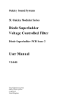
1
Oakley Sound Systems
Filtrex II
PCB issue 1
Analogue Filter Rack
Builder's Guide
V2.1.5
Tony Allgood
Oakley Sound Systems
Carlisle
United Kingdom
Introduction
This is the Builder's Guide for the issue 1 Filtrex II rack module from Oakley Sound. It
contains the schematic description, parts list and testing procedures.
For the User Manual, which includes a brief history about the development of the module, a
guide to the front panel controls and some notes about the power pack needed to power your
module, please visit the project webpage at:
http://www.oakleysound/filtrex.htm
For general information regarding where to get parts and suggested part numbers please see
our useful Parts Guide at the project webpage or http://www.oakleysound.com/parts.pdf.
For general information on how to build our modules, including circuit board population,
mounting front panel components and making up board interconnects please see our
Construction Guide at the project webpage or http://www.oakleysound.com/construct.pdf.
This is an early version of the documentation. If you do find any errors, even silly little ones,
please do let me know either directly by e-mail or via the Forum or mailing list.
Circuit Description
Like many complex analogue circuits the Filtrex circuit can be split up in to little bits. The first
bit we will look at is the pre-amplifier stage on page one of the schematic.
The pre-amp is built around U1. I have specified the low noise audio op-amp, the OPA2134
The pre-amplifier is a two stage design. The first stage is a non-inverting amplifier whose
voltage gain can be varied from 1 to 12. C1 keeps the gain for DC and very low frequency
signals at near to one. This prevents any offsets within U1 from being amplified unnecessarily
C3 provides a little bit of high frequency roll-off to keep the amplifier stable.
The second stage of the pre-amp is an inverting amplifier. The GAIN pot is used in a slightly
offbeat way. It is in both the feedback and the input resistors. This way we can control the
gain over a wide range from -0.4 to -10.1. The minus in these numbers shows the inverting
properties of the amplifier.
The voltage gain of the two pre-amplifier stages in tandem can be varied from -0.4 to -122. A
gain of 0.4 means that the output of the pre-amp is only 40% of the input level. While a gain
of 122 means that the output level is 122 times bigger than the input. In audio circles this
would normally defined in dB. This pre-amplifier will give you a gain from -8dB to +42dB.
Because the pre-amplifier is made from a inverting and non-inverting stage, the overall
behaviour is inverting. This means the output is completely out of phase with the input. This is
not a problem since the inversion is corrected later on the Filtrex.
2
Q7 and associating circuitry drive the peak LED. This is designed to light up just as the ladder
filter starts to show heavy distortion.
The main audio path continues on to the filter ladder itself via one half of the resonance pot.
However, the pre-amp also provides the signal for the 'dry/wet' circuit and the envelope
processor. We will deal with these two later.
The filter is based around the traditional ladder as designed originally by Dr. Moog. I have
used THAT300 matched NPN array for the top and bottom pairs in the ladder. This minimises
control current breakthrough to almost zero. Current breakthrough manifests itself as a copy
of the modulating signals on the output. Generally, this is not a good thing. ‘BAL’ biases the
base of the left hand bottom pair (U2, pin 9), via R20, by a small amount to even out any
differences within the ladder. This minimises breakthrough still further.
Two of the rungs of the ladder are ‘sniffed’ by a differential amplifier. Each of these is
identical, based around the classic three op-amp implementation. They are all DC coupled, and
rely on ‘close’ matching to remove any DC offset. A differential amplifier is a device that
makes larger the voltage difference between two points. In our case, the voltage across the
top and bottom filter capacitors. The gain of the differential amplifiers is set higher than
normal ladder filters to improve signal to noise ratio in the following mixer stage. C17 and
C18 provide AC coupling of the outputs to remove the slight DC offset from the top
differential amplifier.
The resonance in a moog ladder filter is controlled by the level of audio feedback applied to
the bottom pair of transistors from the output of the differential amplifier at top rung of the
ladder. The level of is typically controlled by the resonance pot, wired as a variable resistor
and a trimming resistor, TRIM. It is traditional to use a 50K reverse log pot for the resonance
control in the classic moog ladder circuit. When set to a value of 50K this pretty much allows
the feedback path to be ignored, and no resonance can be heard. The ‘reverse log law’ is
needed so that as you turn the pot the resonance increases smoothly. An ordinary linear law
pot would do nothing for most of its travel, and then all the resonance would be introduced in
the last quarter of a turn. Not very ‘smooth’ or musical. Unfortunately, 50K reverse log pots
are difficult to find and quite expensive.
In the Filtrex-II, we use an 50K linear pot, but we wire it as a potential divider and not as a
variable resistor. The drawback of using a pot on its own like this is that it has a variable
output impedance and the ladder is therefore unbalanced, the degree of which depends on
where the resonance control is set. We get around this by using a buffer on the pot's output.
U3, a unity gain voltage follower, or buffer, 'sniffs' the voltage at the wiper of the resonance
pot and provides a copy at its own output that has a constant impedance.
The resonance pot is a dual gang type too. One gang controls the feedback loop as we have
seen, and the other sets the gain of the input. Normally the passband gain of a moog ladder
decreases as you turn the resonance up. In other words the volume drops as you increase the
resonance. This can be quite a problem for a post processor like the Filtrex. So in the Filtrex,
the input level is automatically turned up as resonance increases. Thus the overall effect is of a
constant volume at all values of resonance. I thought this was quite clever of me to invent a
way of doing this without increasing noise levels. However, I found out later that the very
same principle was used in the Roland SH-2000 as long ago as 1974.
3
The other half of U3 acts again as a voltage follower on the wiper of the gain control part of
the resonance pot. This ensures that the ladder's input is fed from a constant resistance no
matter where the resonance pot is positioned.
C11 provides the appropriate decoupling and is sufficiently large so as to allow the filter to
oscillate above 200Hz or so.
Four inputs control the filter cut-off frequency via an exponential convertor based around U9.
The filter frequency can be directly controlled with the FREQ pot via R63. R65 sets the
sensitivity of the envelope processor’s output. While R67 does the same job for the LFO. The
CV input provides a nominal 1V/octave response, and would normally be accessed via a jack
socket on the rear panel.
The exponential convertor is temperature compensated. R61 is the positive temperature
coefficient resistor providing an approximate cancellation of the exponential convertor’s
inherent temperature coefficient.
Note the two pin header, STV, and R60. These allow two Filtrex-II modules to be ganged
together to form stereo processing. There is more about this later in the document, but we can
see that the output of the CV summing amp is present at pin 1, while a second CV input is
made available at pin 2. The master Filtrex-II will be sending the CV signal via pin 1 on the
STV header to pin 2 on the slave's STV header. This way the master Filtrex-II board will also
control the slave's cut-off frequency. It would be expected that the connection be done via a
switch so the linking could be turned on or off from the front panel.
The audio path continues from the filter’s differential amplifiers by going on to the mixer
stage. This is shown on page two of the schematics at the top of the page. The mixer stage is
designed to combine the three audio signals created by the Filtrex so far: The first and fourth
rung ladder outputs, which will make up the ‘fizz’ and ‘smooth’ outputs respectively. And the
main pre-amplified signal which will go to the 'wet/dry’ balance control.
The two filtered signals go to identical ‘reversible attenuator’ circuits. U5 is wired as two
inverting amplifiers, each with a gain of -1. Each inverted signal is applied to one end of a pot,
while the non inverted signal is applied to the other. By simply moving the wiper of the pot to
one side or the other determines which signal is dominant. When the wiper is in the middle
position the two signals cancel each other out and the voltage is zero. U7a (pins 1, 2, 3) is
configured as an inverting summer. This circuit combines the voltages at each wiper. R38 and
R39 are deliberately low in value when compared to the 50K of the pots. This loads the
relative high impedance output of the pot and warps the law of the pot. This allows the central
null point to be more easily found.
U7b (pins 5, 6,7) in conjunction with the dry/wet pot and R45 form the output balance circuit.
This block allows the user to select between the output of the filter mixer or pre-amplified
signal. It is easy to see how it works when you consider the action of the wiper moving
between one end of its track connected to U7 pin 1 and the other which is connected to the
output of the pre-amplifier.
4
The output of the mixer stage is fed via a DC blocking capacitor to the ‘Volume’ pot. The
wiper of this is connected to the final output amplifier stage. If we ignore R51 for the moment,
this is a low noise inverting amplifier circuit with a gain of -4.7. The op-amp chosen is the
5534 which is capable of driving larger currents than most ordinary devices. C26 and R54
form a compensation circuit to allow the op-amp to drive fairly high capacitive loads. It has no
effect on the audio performance, but reduces any chance of high frequency ringing in long
cable runs. A full explanation of this is beyond the scope of this user guide, but more
information can be found on the Analog Devices website in their Applications Note AN-257.
Now let us look at R51. This connects to pin 2 of the output header which goes to the ring of
any connected jack plug. Now if the inserted jack is a mono one the ring will simply be
shorted to the sleeve by the action of the jack plug. There is no voltage across R51 and pin 3
of U8 is held at 0V. Therefore it behaves in much the same way as a traditional unbalanced
output. However, if you use a TRS plug (a stereo jack plug but carrying only a mono signal)
then the audio output of the Filtrex-II appears as if to have some sort of ground loop
immunity, almost as if it were an electronically balanced output. The inclusion of R51 and R50
creates a ground compensated output circuit. Pin 2, the ring connection, functions as an input
in which any ground currents travelling down the connected cable are passed into the output
amplifier and subtracted from the audio signal by the differential amplifier action of U8. Thus
this output circuit can be used as you would a traditional balanced dual output signal even
though it is actually an output and an input.
That completes the description of the audio path. Now let us take a look at the processing
circuitry of the Filtrex. Staying on page two of the schematics, the second set of circuits down
the page belongs to the full wave rectifier and threshold detector. This takes its input from
wither the pre-amp output or the external side chain input. The choice is determined by the
‘cont’ switch.
The switch's wiper leads straight into some amplification based around U14a. This is a noninverting amplifier of around 2. The main pre-amp is expected to produce a maximum output
of around 5Vp-p in normal use, so U14a boosts this signal up to 10Vp-p. The amplified signal
is now full wave rectified by the circuitry based around U14b and associating circuitry. Full
wave rectification can be described by the mathematical ‘absolute’ function. In other words,
the output of the full wave rectifier (FWR) is always positive. If you present +10V to the
input, you will get +10V. But if you present it with -10V you will also get +10V. Likewise,
-5V turns into +5V, -3V into +3V. Now if you put an audio signal into this circuit, you will
get a series of positive bumps that correspond to the up and downs of the audio signal.
U14d forms a special buffer circuit. This configuration, allows the op-amp to drive medium to
high capacitive loads without instability. We also saw it being used in the output amplifier of
the Filtrex. The output of the full wave rectifier is therefore protected by the odd load
presented by the next set of circuits.
Now, no real time system can recover envelope information without some disadvantage of
some sort. Some systems employ the peak and droop method. These are fast to respond to
sudden changes in loudness or envelope. They work by simply charging a capacitor from the
FWR through a diode. The capacitor is then discharged through a resistor, sometimes
variable, causing the stored voltage to droop at a determined rate. However, they are often
plagued by ripple. Ripple is the bumps from the FWR creeping through to affect the required
5
output. This tends to manifest itself in a ‘buzz’ to the output CV. If you increase the discharge
resistor, you can reduce the bumps but this tends to not allow the CV to drop quick enough
when the sound ends.
Another method involves low pass filtering of the FWR output. This leads to less bumps if the
correct filter cut-off frequency is chosen, but does lead to longer attack times. There are more
complex ways too, involving sample and holds and other clever methods. Some three years
ago when I designed my VCF-1 Filter rack, I sat down and compared the many different
circuits. I didn’t want a complex circuit, I didn’t have the board space to do that. So I stuck to
either filtering or the peak and droop topologies. The one that most excited me was the low
pass filter, but only if you got the frequency right. I decided to use a four pole filter with the
cut-off frequency at around 33Hz. I chose the best sounding and the most natural with all
sound sources. This method is not as quick at responding to fast attack signals as the peak
and droop but it did react equally to rises and falls in signal level. However, the peak and
droop wouldn’t be forgotten, I used that for the threshold detector.
In the Filtrex, things are different. The output of the full wave rectifier, labelled FWR on the
circuit, is passed to a special circuit called the ‘lag processor’. This is cleverly combined with
the function of the envelope generator and is described in detail later. At this point I will just
say that it functions as a simple low pass filter with controllable rise and fall times.
But let us stay on page two for now. To create a gate signal we need a very fast response. In
an ideal world this signal must go high the moment the signal arrives and goes low the
moment the signal dies away. In this case I have used the peak and droop method. This does
give us a fast as response as possible, but what about the ripple. Well, ripple is not that
important here. Remember the gate output only goes high or low. What we have to do is
make sure our gate doesn’t ‘rattle’ when it picks up the ripple. In other words, we need our
gate to come cleanly on and off with no spurious states as the signal rises and falls.
U14b (pins 5, 6, 7) is a comparator. This is a device based around an op-amp that determines
whether a signal is higher than a pre-selected threshold voltage. The threshold voltage is
controlled by the user, and is set by the ‘Threshold’ pot. The threshold voltage can be set
between 12V and 0.7V. C44 is charged via D15 from the FWR output. D15 allows the
capacitor to be charged up, but not discharged, by the FWR’s output. R104 allows the
capacitor’s stored peak voltage to droop at a controlled rate.
Most gate extractors provide a gate signal when the voltage on the capacitor is above a certain
value. The Filtrex is different. Once the gate does go high, a certain proportion of the opamp's
high level output is fed back, via D16, to keep the input higher. This forces the comparator to
stay high longer than it would normally do. This allows more ripple to be present before
‘rattling’ occurs, giving us a cleaner edge to our gates. You don’t have any control over this
amount of positive feedback, it is set by the value of R105. Now many good comparator
designs have a little positive feedback anyway, its called hysteresis, and in our case it is
provided by R106. But the additional path offers a type of one way hysteresis that gives us
better high to low gate transitions.
The comparator’s output is fed via D17 to a transistor Q13. This transistor is turned on when
the comparator’s output goes positive. D17 protects the transistor from damaging negative
6
output voltages. Q13’s collector will be pulled down to ground when the transistor is turned
on. This in turn controls the envelope generator’s logic circuitry described later.
Lets have a look at the third page and the envelope processor itself. This is quite a hard bit to
understand.
The heart of this unit is the circuitry based around U10b (pins 5, 6, 7). This, along with the
‘up’ and ‘down’ pots, make up the lag generator. What is a lag generator? Basically it is a
capacitor, C37 in this circuit, that can discharged and charged at a controlled rate. The level to
which the capacitor charges to, or discharges to, is determined by the input voltage applied to
pin 5 of U10. The voltage across the capacitor will directly control the output of the envelope
processor.
U12 is an analogue switch. It is a good old 4016, and this IC is found in hundreds of synth
circuits. In the Filtrex, it doesn’t do a great deal other than select which mode the envelope
processor is going to be in. The 4016 is controlled by the ‘mode’ switch. For the envelope
processor to be in envelope follower, or EF, mode, the FWR output needs to be patched into
the lag generator. U12 (pins 6, 8, 9) switches on, and U12 (pins 10, 11, 12) is off. The
positive voltage that is being produced by the FWR will now start to charge or discharge C37
up and down. The speed of the charging will be controlled by the ‘up’ pot, and the speed of
the discharge wil be controlled by the ‘down’ pot. U10c (pins 8, 9, 10) buffers the voltage
across C37 to create the positive going EF output signal. U10d (pins 12, 13, 14) inverts this to
produce negative going voltages. The ‘envelope’ pot controls the depth of the effect. The
position of the pot’s wiper will determine the polarity and the level of the final output signal.
D3 and 4, along with R58, create a dead band around zero volts so the pot doesn’t have to be
exactly in the middle for no modulation.
In EG mode, U12 is switched over to allow the output of the EG logic circuity to control the
lag generator. The output of this logic circuitry is either high, +7.5V or low, 0V. The logic
circuitry can operate in two modes, attack-decay (AD) or attack-release (AR).
Several sources can initiate the attack phase. One is the external ‘gate’ signal. This is a switch
type signal that is either at around 0 volts when off, or any positive voltage greater than 3V
when on. The Filtrex can easily handle greater voltages, within reason, without damage. D5
protects Q11 from any negative inputs.
Other sources of triggering the attack phase come from the LFO and the threshold detector
already discussed in this document. Both of these trigger the unit by pulling the collector of
Q11 down to zero via the TRIG bus.
When a positive gate signal arrives, Q11 turns on and pulls its collector down to ground or
0V. This inverse version of the applied gate signal is sent to two destinations. One is another
transistor, Q14. This is configured as another inverter. Thus the output of Q14 produces a
copy of the gate signal that swings from 0 when off to +15V when on. R86 passes some
current back to the first transistor. This creates a type of Schmitt trigger action which makes
the transistors change state faster. It therefore allows slowly varying signals to trigger the
Filtrex. For example you can use a slow sine wave or aftertouch CV to fire the EG.
7
The output of Q14 is passed on to a CR network that acts as a differentiator. This circuit
produces a positive voltage spike when the gate goes high. The duration of the spike is
determined principally by the values of C43 and R93. D12 prevents a negative spike being
produced when the gate goes low. The positive spike triggers an RS flip-flop circuit based
around two NOR gates, U13.
A flip-flop is a sort of a one bit memory, or latch. Once triggered by a positive going pulse at
pin 12, it stays latched. You can only reset it by removing the power or a reset pulse at its
other input, pin 9. When the flip-flop is latched, pin 10 goes high and pin 11 goes low. The
output at pin 10 is passed via R89 and U12 to the lag generator’s input, thus causing C37 to
start to charge upwards. R89 is chosen to interact with R73 to give an input signal of 7.5V in
the high state.
In any mode, removing the gate will reset the flip-flop. The inverted gate signal from Q11
goes to a second differentiator, C39, R92 and D11. When a gate signal is removed, the
positive going edge runs through U13 (pins 1,2,3 & 4,5,6) to reset the flip-flop. Thus
removing a gate signal will cause the lag generator’s output to fall.
Another way to reset the flip-flop is in the AD mode. This utilises the actual output of the lag
generator to control the discharging process. When the output of the lag generator exceeds a
certain value, approximately +3.8V, the flip-flop is reset and the output voltage will drop.
This job is performed by a comparator based around U10a (pins 1, 2, 3) and Q10. The output
of the lag generator is passed onto the comparator by another analogue switch U12 (pins 1, 2,
13). In AR mode, this is switched off and the input to the comparator is held low by R83. In
AD mode, the switch opens to allow the comparator to sniff the output of the lag generator.
When the voltage exceeds +3.8V or so, the comparator’s output goes from 0V to +15V. This
tells the flip-flop that the attack phase is over and the decay phase is about to start. Pin 10
therefore goes low and C36 is discharged via the ‘down’ pot.
R69 and R70 set the +3.8V threshold level. R77 with R78 provides a thin slice of positive
feedback to force the comparator to switch cleanly... it is another Schmitt trigger again.
The LFO circuit is quite simple. It is on page two of the schematics.
The first TL072 op-amp, U16a (pins 1, 2, 3) forms part of the integrator. Any positive voltage
applied to the right of R120 will cause the voltage to fall at the output of the op-amp. The
speed at which the voltage falls is controlled by C52 and the size of the voltage applied to
R120. If the applied voltage is negative the op-amp’s output will rise. It is the integrator’s
output that will be used as the source for the triangle wave output.
The second half of the TL072 op-amp is used as a Schmitt trigger. Its output is either high at
+13V, or low at -13V. If the output of the Schmitt is initially low, it requires +6V at the
output of the integrator to make it go high. The integrator will need to produce an output of
-6V to make the Schmitt go low again.
To make any oscillator you normally require an output to be fed back into the input. In a
standard LFO like this one, the integrator is fed by the output of the Schmitt trigger. Thus, a
8
low at the output of the Schmitt causes the integrator to rise. When the integrator’s output
reaches a certain point, the Schmitt switches state and the integrator’s output falls. The
Schmitt trigger changes state once again, and the process repeats itself....
The ‘LFO-rate’ pot allows a only a controlled proportional of the Schmitt's output voltage to
reach the integrator. If the proportion is large, the voltage on R120 is large, and the integrator
sweeps fast. If the proportion is small, the integrator sweeps slowly. R116 sets the minimum
speed. Don’t be tempted to lower this value any more to get really slow sweeps. Input errors
within the integrator op-amp will take over and your LFO won’t oscillate any more.
With C52 at 100nF the range of the LFO is about 0.05Hz (one cycle in 20 seconds) to 50Hz.
If you make C52 a 220nF capacitor the LFO will be proportionately slower and you will have
a range of 0.02Hz to 23Hz.
The square wave output is derived from the Schmitt trigger’s output. D25 allows only positive
excursions through. R123 and C55 act as a simple low pass filter to round of the waveforms
edges a little bit. Very fast edges end up as CV breakthrough on the main audio output and are
pretty unpleasant.
The trigger output is simply generated by a transistor, Q12, that turns on when the output of
the Schmitt trigger goes high. The ‘auto’ switch switches the function off by shorting the base
to the emitter when not required.
The last thing to describe is the power supply. This is a standard ‘three terminal regulator'
design straight out of the data book. R96 and C42 provide a decoupled version of +15V for
the logic circuitry. The logic circuitry can generate little spikes on the power supply, that
could get back into the audio if not decoupled properly. R9 and the ‘on’ LED provide power
supply indication. I have put it on the negative supply only to even up the power drains on
both rails.
The Filtrex’s power supply can function either with a half wave rectifier for wall warts, or with
full wave for internal transformers. This will covered in more detail later on the document.
9
Parts List
For general information regarding where to get parts and suggested part numbers please see
our useful Parts Guide at the project webpage or http://www.oakleysound.com/parts.pdf.
The components are grouped into values, the order of the component names is of no particular
consequence.
A quick note on European part descriptions. R is shorthand for ohm. K is shorthand for kiloohm. R is shorthand for ohm. So 22R is 22 ohm, 1K5 is 1,500 ohms or 1.5 kilohms. For
capacitors: 1uF = one microfarad = 1000nF = one thousand nanofarad.
To prevent loss of the small ‘.’ as the decimal point, a convention of inserting the unit in its
place is used. eg. 4R7 is a 4.7 ohm, 4K7 is a 4700 ohm resistor, 6n8 is a 6.8 nF capacitor.
Please note that if you are building a stereo version of this module you will need two
Filtrex-II boards. One of them will be built as a Master and the other as a Slave. For the
Slave module you should not fit parts marked with a *. Please see later in this
document for a suggested method on how to wire the two modules together.
Resistors
All resistors 5% or better 0.25W types. Those items marked with 1% need to be 1% metal
film, or better, 0.25W metal film resistors. For the sake of clarity it may be simpler to make all
resistors 1% metal film types.
R61 is a +3000ppm/K positive temperature coefficient resistor.
10R
22R
36R
47R
75R
330R
470R
1K
1K +3000ppm/K
1K5
2K2
2K2, 1%
2K7
3K
3K9
4K7
4K7, 1%
6K8
10K
R50
R5, R53, R109, R4, R52, R115, R121, R96, R80, R81, R8, R122
R51
R111, R116
R54
R10, R18, R19, R13, R17
R12, R20
R11
R61
R117
R9*, R91, R56, R46, R57
R25, R24
R47
R100
R1, R15
R87, R97, R74
R41, R43, R30, R34
R70, R39, R6, R38
R123, R3, R78, R58, R113, R55, R104, R110
10
10K, 1%
12K
15K
22K
22K, 1%
33K
39K
47K
56K
68K
100K
220K
330K
470K
680K
1M
3M3
R42, R32, R31, R44
R99
R40, R37, R69
R75, R14, R7, R108, R112
R28, R27, R22, R23
R16
R107
R85, R29, R26, R35, R71, R36, R124, R33, R82, R79
R59, R60
R65
R125, R101, R120, R73, R68, R88, R114, R119, R98, R92, R93, R76,
R72, R84, R89, R95, R94, R118, R66, R67, R64, R45, R83, R103
R21, R90, R63
R102
R62, R49, R2
R105
R86
R106, R77
R48 should be left empty and no component fitted.
Capacitors
22pF low-K 5mm ceramic
33pF low-K 5mm ceramic
100pF low-K 5mm ceramic
C7, C3
C48, C28
C26
1nF, 100V polyester
68nF, 63V polyester
100nF, 63V polyester
470nF, 63V polyester
680nF, 63V polyester
1uF, 63V polyester
C43, C30, C39
C12, C13, C14, C15
C32, C52, C20, C21, C35, C54, C55, C41, C50*, C38*
C5, C24
C19, C18, C17, C44
C16
2u2, 63V electrolytic
10uF, 35V electrolytic
22uF, 35V electrolytic
100uF, 25V electrolytic
220uF, 10V electrolytic
1000uF, 35V electrolytic
C51, C33
C37, C22
C56, C53, C34, C6, C8, C4, C49, C25, C27, C45, C11,
C46, C36, C10
C42
C9
C47*, C40*
10uF, 35V non polarised elect
22uF, 35V non polarised elect
47uF, 35V non polarised elect
C23, C31
C1, C2
C29
Non polarised capacitors can sometimes be called bipolar. Unlike ordinary polarised
electrolytic capacitors they can be put into the board any way around.
11
Discrete Semiconductors
BC549 or BC550
1N4002 or 1N4004
1N4148 or 1N914
Q1-15
D8, D23, D9*, D13*, D14*, D18*, D19*, D24*
D1, D2, D3, D4, D5, D6, D11, D12, D15, D16, D17, D20, D21, D22,
D25
BAT-42
D7, D10
LED 3mm green
TRIG
LED 3mm red/green LFO
LED 3mm red
PEAK
LED 3mm yellow
ON
The LFO LED is a bi-colour LED in a water-clear package. Do not fit an ordinary single
colour LED in this position.
Integrated Circuits
OPA2134PA
NE5534
TL072
TL074
7815
7915
THAT300P
4001
4016
U1, U7
U8
U3, U5, U6, U9, U16
U4, U10, U14
U15*
U11*
U2
U13
U12
Pots
All pots 16mm Alpha or Alps types.
50K linear dual gang
1M log
50K linear
10K linear
50K log
RESONANCE, GAIN
UP, DOWN
SMOOTH, FREQ, FIZZ, DRY/WET, THRESHOLD, ENVELOPE
VOLUME
LFO-RATE, LFO-DEPTH
Trimmers
22K trimmer
470K trimmer
TRIM
BAL
12
Switches
SPST on-on
SPST on-off-on
CONT, AUTO, WAVE
MODE
Miscellaneous
Heatsinks TO-220 clip-on
2-way 0.1” KK Molex header
3-way 0.1” KK Molex header
2-way 0.1” KK Molex housing
3-way 0.1” KK Molex housing
16mm Alpha pot brackets
2 off
4 off
1 off
4 off
1 off
13 off
for U11 and U15
INPUT, SIDE, CV, GATE
OUTPUT
INPUT, SIDE, CV, GATE
OUTPUT
4 off
1 off
1 off
Input, Side chain input, CV, Gate
Output
Power In
Off-board Parts
These are fitted to the rear panel
1/4” mono sockets
1/4” stereo (TRS) socket
Suitable power plug
I recommend plastic shrouded sockets for both the audio, CV and power sockets. This will
reduce the risk of earth loops.
Additional parts required for stereo operation on both boards
2-way 0.1” KK Molex header
2-way 0.1” KK Molex housing
4-way 0.156” KK or MTA header
4-way 0.156” KK or MTA housing
2 off
2 off
1 off
1 off
STV, ST-A
STV, ST-A
MOTM
MOTM
You will also need a power source of some kind. The recommended supply is a wall-wart
supplying 15V AC at 300mA minimum. See later for more information.
A small amount of insulated multistrand wire is needed. This will be used to connect the
sockets and power supply to the board.
IC sockets are to be recommended, especially if this is your first electronics project. You need
eight 8-pin DIL sockets, and six 14-pin DIL sockets. Choose ‘turned pin’ or ‘dual wipe’
types.
13
Connections
You are going to need five 1/4” jack sockets, four mono and one stereo, to connect your PCB
to the outside world. Each jack is connected to its respective 0.1” headers on the PCB. The
stereo jack socket is to be fitted in the Output position. This is because the audio output of the
Filtrex-II is ground compensated and requires three connections to the outside world. The
stereo one is therefore not being used to carry a stereo signal but a TRS or tip-ring-sleeve
connection. We can use this like we would a balanced output signal but with full compatibility
with ordinary unbalanced connections too.
The ground pin on each header is always on the right hand side as you look at the board with
the pots facing forwards. This is pin 1 of the header so the ground pin should correspond to
the square pad on the PCB. Each of these pads will be connected to the respective jack
socket’s ground pin, ie. the one that will connect to the barrel of the plug when it is inserted.
On the two pin headers the signal is sent on the furthest left pin of the header, pin 2 on the two
way headers and pin 3 on the three way header.
For each mono socket, it is a good idea to twist the wires together in pairs. Use two different
colours to tell them apart, and try to keep the wiring as short as possible to prevent picking up
hum and other stray fields. You can use screened cable if you wish, and this should be so if
you are using a wooden case to house the Filtrex. The screen must go to pin 1 of each 2-way
header as it carries the ground. Pin 1 should thus connect to the socket's sleeve terminal. Pin 2
should connect to the tip terminal of the socket.
For the stereo (TRS) socket you have three connections to make. If you are wanting to use
screened cable you will need to use special balanced cable which comes with a single screen
that overlaps two identical conductors. Like the other connections pin 1 is the ground and
should be connected to any shield if you are using screened cable. As before this should go to
the sleeve lug of the socket. The audio signal is carried from pin 3 of the header and this
should connect to the tip lug of the socket. Pin 2 is the ground compensation input and should
connect to the ring of the output socket.
I recommend that you use plastic sockets and not ones with a metal mounting bush. This
allows any metal case to float electrically with respect to the socket's ground connection.
However, I do recommend you ground your case in a controlled manner as this will reduce the
likelihood of picking up radiated hum fields from other pieces of equipment and wiring. What
we need to do is tie our case to 0V but not tightly.
Fit a M4 bolt through the rear panel of your case. With a washer, spring washer and nut,
fasten a solder tag to it. Solder a 47R 1/4W resistor to the tag. Then to the free end of the
resistor solder a wire onto it. Attach the other end of the wire onto the AC0 pad on the Filtrex
board. You can use a bit of heatshrink sleeving around the resistor and tag to make it look a
little neater and prevent wire/resistor junction shorting to the case.
If you have used metal sockets then you don't need to ground your case since your case will
be grounded very tightly via all the sockets. However, this can cause earth loop problems if
you then mount your case into a rack with other pieces of equipment in it.
14
Power Supply
The recommended option is to use an insulated wallwart or AC adapter. These can be bought
from most places and are used external to the Filtrex housing. They are very safe since all the
nasty dangerous stuff is kept inside the wall-wart. You won’t hurt yourself with the output
from one of these unless you stick it in your mouth!!
You need a 15V or 18V alternating current (AC) output at 250mA or higher rating. Do not
use a DC output type. Although the latter are the most common type of wallwart for guitar
effects pedals, they will not work with the Filtrex. To reiterate, because this is really
important, it must say 15VAC or 18VAC on it somewhere.
In the UK they can be bought from Maplin Electronics. The one we recommend is their part
number N57AT. This is a variable supply which means it can supply a variety of different
voltages. The adjustment is on the underside of the unit. Simply set this to 15V with a small
blade screwdriver.
Some 12V AC output types may also work but this is only because some AC output wallwarts
tend to be poorly regulated and have a lot of overhead. Do be aware that if they do work
some of the time they may not work all of the time. If the voltage does fall below the required
operating voltage of the Filtrex-II the most obvious sign is an audible hum from the outputs.
You will not damage the Filtrex-II by doing this although any connected amplifier or speaker
system may object to the humming.
To connect your wall wart to the Filtrex, you need a suitable connector. The standard type is
the barrel type as found on most effects pedals. Try to get the ones that have a plastic housing.
This means that there is no electrical contact between the case and the power socket. Make
sure you get the right socket for the plug you have on the wall wart. Some wall warts give you
a little bundle of different types to choose from. Either way, make sure the socket you get
allows the plug to slip in easily yet not break connection when wiggled gently. If you are
making up your own plug for it, since it is AC, it does not matter which wire goes to what.
There is no + or -.
The socket must be connected to AC1 and AC2 on the PCB. AC3 is left unconnected and
AC0 is already in use as the resistative grounding lead. If you really have to have a metal
shrouded socket and you have a metal case, make sure the that AC1 is connected to the outer
shroud of the socket, ie. the one that goes to the barrel of the plug. Failure to do so may result
in burnt out wall warts or at the best excessive hum. This is not to do with the polarity of the
AC. This is to do with the fact that the AC1 pad on the PCB is connected to analogue ground.
You don’t want the case to be connected to AC2, which will have a voltage on it that is
bouncing up and down 50 or 60 times a second.
Internal Mains Transformer
The following advice is only for those who know how to wire mains rated equipment safely. If
you do not know how to do this then make no attempt to do so. I do not endorse this method
of powering any Oakley equipment. It is up to you to use your PCB wisely. I take absolutely
15
no responsibility for your actions with this board. I will offer no further advice than what you
see here in italics:
Transformer rating: Secondaries: 18-0-18 @ 250mA or 18-0, 18-0 @ approx 15VA total
Connect common, or centre tap, to AC1 and/or AC0. Others to AC2 and AC3.
Line fuse: T250mA
All mains carrying conductors must be suitably insulated and mounted away from the low
voltage parts of the unit.
All parts of the metal case MUST be connected to mains safety earth. A suitable and secure
bonding point must be made to the case. Note that any case paint or other coating should be
removed from around the bonding point to ensure that the metalwork is making a good
contact to the bonding point hardware. The bonding point should then be connected via a
suitably thick piece of wire back to the earth terminal of the IEC socket or earth inlet
connection.
If you have used a laminated EI transformer, ie. not a toroid, then you should earth the
exposed metal frame of the transformer.
0V on the Filtrex-II circuit board should also be tied to earth. This should be done using a
piece of insulated wire connecting the earth bonding point to pin 2 or 3 of the MOTM pad on
the board.
Powering the Filtrex with the MOTM header
The Filtrex may also be powered from the MOTM or Oakley power busses. The power socket
is 0.156” Molex/MTA 4-way header is marked as MOTM on the PCB. Friction lock types are
recommended. The pin out is as follows:
Power
Pin number
+15V
Module GND
Module GND
15V
1
2
3
4
Pin one is depicted by the diagonal on the legending. If you are using the MOTM system to
power your Filtrex, be sure not to fit the following components which make up the Filtrex's
own +/-15V regulated supply:
U15, U11, D13, D14, D18, D19, D9, D24, C40, C47, C38, C50
You can also use the Filtrex to power other MOTM/Oakley modules using the MOTM
header. However, be sure not to exceed the power rating of the wallwart, transformer,
heatsinks and smoothing capacitors.
16
Trimmers
TRIM: Adjust this trimmer so that the filter bursts into oscillation when the ‘resonance’ pot is
moved close to its maximum setting. The filter should oscillate from about 100Hz to over the
range of your hearing. Or you can adjust it so that it never goes into oscillation at all. This will
prevent you from accidentally damaging your ears, your tweeters and upsetting your
neighbour’s dogs. But hey, that would be boring. Live life in the fast lane. Trim it up so that it
just oscillates when the resonance it up full.
BAL: Listen to the ‘Smooth’ output. Set the Resonance and Frequency pots to their mid
positions. Turn the LFO modulation depth pot to its maximum value and select the triangle
wave. Adjust BAL until the clicking or buzzing becomes minimised.
17
Housing your unit
The PCB has been designed to fit into a standard 1U high 19” rack unit. Your local parts
distributor will probably have these. Good rack units are quite expensive, and will contribute
heavily to the final cost of your completed Filtrex. Expect to pay around 35GBP or so.
In the UK the ones we recommend are made by Bryant Broadcasting or Holt Broadcasting
Services. You can use the Schaeffer Frontplatten database provided on the project webpage as
a template for any drilling of holes in the front panel.
The Bryant and Holt ones are superbly made, but they do not allow you to use a 3mm thick
Schaeffer front panel in place of their own. Their cases actually utilise the front panel as part
of the enclosure. Simply swapping the Bryant or Holt panel with one obtained from Schaeffer
will not work as the case would no longer be able to held together. Bryant and Holt do
custom metal work, so it may be possible to try their services. This is one area I would like to
try in the near future.
Schaeffer are also able to engrave panels that are sent to them. One could send them the blank
Bryant panel and they could engrave this with the Frontplatten database found on the Filtrex
website. I have heard of one person who has tried this and he was very pleased with the result.
Remember if you do decide to do this, you must remove the four mounting holes from the
Frontplatten database before sending it to Schaeffer as these are already present on the Bryant
panel. I am not sure whether this could be successfully done with the grey painted finish of the
Holt panels.
If you buy the cases made by Vero, you will find that the height of the unit internally is quite
restricting. The bottom and lower panels have 6mm folds in them at the front. This effects the
amount of space available for the pots and circuit board at the front panel. It is possible to use
these cases as I have done in the past, but I needed to trim back the three pins on each pot to
prevent them shorting with the case. The pot bracket pins then prevent the case from
touching the pot’s pins.
The other thing to beware is the heatsinks. Don’t let either one of them touch the top panel,
since this would cause major problems. This shouldn’t happen if you make sure the base of the
regulators ICs are fitted within 10mm of the PCB.
For those of you fitting an internal toroidal transformer. Please, please make sure there is no
way the top metal disc of the transformer's mounting can touch the top of the casing. If the
metal support of transformer together with the case makes a complete loop around the core,
then you have a shorted one turn secondary. (‘well, there was a large hum, more of a buzzy
rattle really, then a smell of burning rubber and then a lot of smoke... ’)
The PCB will be supported well by the pots and pot brackets. However, this does give some
people nightmares so in this case it may be a good idea to provide additional support. Small
holes, to fit M3 bolts, have been provided on the PCB to do this. Feel free to enlarge these
holes if you wish. My prototypes have been very happy just supported by the pots.
18
Stereo processing with two Filtrex-II modules – Application Hints
Author's note: We haven't tried this yet with the Filtrex-II, however, the theory is sound so it
should work without issue. We would be interested in hearing from people who have made a
dual unit. Feel free to contact me either directly by e-mail or via the Forum.
Two Filtrex PCBs must be populated. One should be designated Master and one Slave. The
slave one is identical to the master except that it has no onboard power supply. The slave
receives its power from the master using the MOTM headers.
The two 2-pin headers, STV and ST-A, must also be fitted to both boards. STV is an
abbreviation of 'stereo voltage' and ST-A is for 'stereo-audio'. STV will carry the filter cut-off
CV from the master to the slave. ST-A will carry an audio signal from the slave to the master.
You will also need two SPST (or SPDT) switches, or one DPST (or DPDT) switch,
somewhere on your front panel. This will give you the option of switching between two
completely independent Filtrex channels and one stereo dual Filtrex.
I would expect any dual Filtrex to be fitted to a 2U high rack case. The master would be the
upper one and the slave below it. Use the MOTM header to carry power from the master to
the slave. I would recommend using Amphenol 0.156” MTA connections since the wires from
these come out at right angles to the connector and are therefore lower profile. The PCB has
been designed so when using MTA connectors the wires move away from the front of the
board so can be looped from one board to the other.
The heatsinks fitted to U11 and U15 must be closely monitored after first building up a stereo
unit. When being run from a 15V AC wallwart the heatsinks get only slightly warm when
driving a single Filtrex-II. But doubling the power output of the power supply will double the
power dissipation in those regulators. Therefore you may wish to increase the size of the
heatsinks. The Filtrex-II PCB has been designed to accommodate larger heatsinks than the
standard ones.
To link the two Filtrexes together you need to allow the CV signal from the master Filtrex to
affect the cut-off frequency of the slave. To do this connect pin 1 of STV on the master to pin
2 of STV on the slave. Wire your switch so that this signal can broken by the action of
opening the switch.
To allow the master's envelope follower and threshold detector circuit to work from the
slave's audio input or side channel, that audio signal must be passed up into the master's side
channel amplifier based around U14a. To do this connect pin 1 of ST-A on the slave to pin 2
of ST-A on the master. Again, wire your switch so that the connection can be broken when
the switch is opened.
You can switch STV and ST-A together with a DPST (or DPDT) switch, or you can switch
each independently with a SPST (or SPDT) switch. One switch lends itself to a simpler front
panel design but there may be times when you want the master to not listen to what the slave
is processing.
19
Final Comments
If you have any problems with the module, an excellent source of support is the Oakley Sound
Forum at Muffwiggler.com. Paul Darlow and I are on this group, as well as many other users
and builders of Oakley modules.
If you can't get your project to work, then Oakley Sound Systems are able to offer a 'get you
working' service. If you wish to take up this service please e-mail me, Tony Allgood, at my
contact e-mail address found on the website. I can service either fully populated PCBs or
whole modules. You will be charged for all postage costs, any parts used and my time at
25GBP per hour. Most faults can be found and fixed within one hour, and I normally return
modules within a week. The minimum charge is 25GBP plus return postage costs.
If you have a comment about this user guide, or have a found a mistake in it, then please do let
me know. But please do not contact me or Paul Darlow directly with questions about sourcing
components or general fault finding. Honestly, we would love to help but we do not have the
time to help everyone individually by e-mail.
Last but not least, can I say a big thank you to all of you who helped and inspired me. Thanks
especially to all those nice people on Muff's Forum and the Synth-diy and Analogue Heaven
mailing lists.
Tony Allgood at Oakley Sound
Cumbria, UK
© March 2010 – updated August 2012
No part of this document may be copied by whatever means without my permission.
20