1
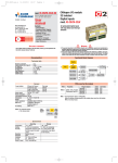
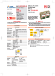
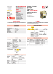
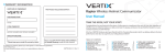
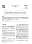
AO-08DP-uso-e
12-10-2011
12:19
Pagina 1
mod. IO-CB/AO-08DP-00
M.U. IO-CB/AO-08DP-2/07.07
Cod. J30-478-1AAO-08DP E
ISO9001 Certified
User
manual
Ascon Tecnologic S.r.l.
via Indipendenza 56,
27029 - Vigevano (PV), Italia
Tel.: +39 0381 69871,
Fax: +39 0381 698730
www.ascontecnologic.com
Contents
- Characteristics
- Functional Block Diagram
- PDOs used by the module
- Hardware Set-up
- Parameter configuration
- Commands
- Emergency messages
- Parameter Store/Restore
- Object Dictionary
E
CANopen I/O Module
8 Ch. ±10V Fast/Enhanced
Analogue Outputs
mod. IO-CB/AO-08DP
Through a software command each
AO-08DP can be configured to operate in fast or in enhanced mode.
The first part of this manual contains
those informations that are module
specific, then each configuration will
be separately described.
COMMON CHARACTERISTICS
APPLICABLE STANDARDS
WARNING
The AO-08DP module is suited for the CiA DS301 protocol [1] and implements the CiA DS 401
standard Device Profile, as far as the Analogue Output Function Block is concerned [2].
1) The product described in this manual should only be installed, operated and maintained by
qualified application programmers and software engineers who are familiar with automation
safety concepts and applicable national standards.
2) This product supports the Parameter defaults indicated by CiA standards, in addition, some parameters have a factory set (value present in the module when comes from the factory). The default
values can be loaded with the restore command, but after the restore, factory set values are lost.
Characteristics
Hardware Set-up
Technical data
Hexadecimal rotary switches, service and I/O LEDs
±0.1% FS
0.005% FS/K
V > 600Ω
16 bit
±10 V
Fast mode:
5 ms
Enhanced mode:20 ms
30 V
Top view
Lo
ide
nt s
Fro
LED
Status
ON
RUN Blinking
Single flash
OFF
ON
Single flash
ERR Double flash
Triple flash
OFF
ON
ST Blinking
Single flash
OFF
PWR ON
OFF
•
Hi
Accuracy at 25°C
Temperature coefficient
Load impedance
Digital resolution
Output range
Conversion time (4 channels)
Overvoltage protection
•
Negative
screwdriver
0.4 x 2.5 mm
General
3 way isolation
Power supply
Power consuption
Dimensions
Weight
Safety regulations
EN61010-1
CE marking
800 Vp
24 Vdc; –15...+25%
6W
L: 76; H: 110; W: 65
220 g
Isolation class II (50 Vrms)
Installation cathegory II
Pollution degree 2
EN61131-2
3 way isolation diagram
Fieldbus
Logic
AO
channels
1-8
Power supply
800Vp
Environment
Operating
-10...+65°C
5...95% non condensing
Appropriate measures must
be taken against
humidity >85%
Mounting
Vertical, free air
Protection
IP20
Vibrations (3 axes) 10...57Hz 0.0375mm
57...150Hz 0.5g
Shock (3 axes)
15g, 11ms half sine
Temperature
Relative
Humidity
•
•
Meaning
Operational
Pre-operational (CANopen)
STOPPED
Device in RESET state
BUS OFF
Warning limit reached
Error Control Event
Sync Error (CANopen)
No error. Device working
DIAG Error
INIT and DIAG running
Baud rate setting
Module OK and ready
Module Power Supply ON
Module Power Supply OFF
Bit Rate and Node ID configuration
Bit rate
Node ID
Baud rate
Lo switch
kbps
1
20
2
50
3
100
4
125
5
250
6*
500
7
800
8
1000
Bus length
m
2500
1000
500
500
250
100
50
25
Hi
Lo
switch switch
0
1
0
2
7
F
Valid ID Node
01h (address 1)
02h (address 2)
7Fh (address 127D)
Notes: * Default value
Procedure for Node ID and Bit Rate configuration
Storage
-40...+85°C
5...95% non condensing
For a short period, slight
condensation may appear
on the housing
The HI and LO hexadecimal rotary swithches set the module’s Bit Rate and CAN Node ID.
During the configuration, the module must be off line and the CAN bus must be physically
disconnected.
To configure the module, follow the procedure:
1 Turn the Power OFF
2 Set the HI switch to “F”
3 Select the desired Bit Rate value by setting the LO switch following the table
(e.g. “8” for 1 Mbps)
4 Turn the Power ON
5 Shift the HI switch to “E” (all the module service LEDs should flash)
6 Turn the Power OFF. Now configure Node ID
7 Set the HI and LO switches to the desired valid Node ID following the table
8 Turn the Power ON.
Alternatively, at step 7 set the value 00h. Then, at the next Power ON, the last valid stored
value will be resumed as Node ID.
Default values:
Bit Rate = 500 kbps, Node ID = 127D
AO-08DP-uso-e
12-10-2011
12:19
Pagina 2
AO-08DP FAST/ENHANCED CONFIGURATION
The AO-08DP module comes configured as Fast analogue module. The user can change the module configuration from FAST to ENHANCED modifying the
status of an entry of the Object dictionary.
Index 3010h - Fast/Enhanced mode set
01h: Fast mode (default)
00h: Enhanced mode.
The new mode will be active after a Power OFF-Power ON cycle.
AO-08DP FAST ANALOGUE OUTPUTS CONFIGURATION
When the AO-08DP is configured as Fast analogue module, each output is configured as ±10V
Commands
Fast Mode Functional Block Diagram
Signal
conditioning
Receive
Error
mode
Index 200Ch - Analogue Output channel status
DAC
The device has its own internal state machine. It is possible to move through this by
sending appropriate values to the Index 200Ch, following the table below.
4
Switch
if 0h
Device
failure
Error
value
3
Ready
1
2
Run
Error
3
The analogue output function block describes, for each output channel, how received
values are actuated. An “error mode value” is provided as well.
The signal conditioning block only traduces a 16 bit integer into linear physical values, i.e:
• 8000h → min. value (-10V)
• 0000h → half value (0V)
• 7FFFh → max. value (10V)
PDOs used by the module
RPDO
Properties
Mapped objects
Index Sub-index
Write Output 16-bit ch 1
6411h
01h
COBID: 300h + NodeID Write Output 16-bit ch 2
6411h
02h
RPDO 2 Transmission Type: 01h * Write Output 16-bit ch 3
6411h
03h
Write Output 16-bit ch 4
6411h
04h
Write Output 16-bit ch 5
6411h
05h
COBID: 400h + NodeID Write Output 16-bit ch 6
6411h
06h
RPDO 3 Transmission Type:01h * Write Output 16-bit ch 7
6411h
07h
Write Output 16-bit ch 8
6411h
08h
Note: * The Transmission Type is configurable: 01h is the factory set (value present in the
modules when come from the factory); FFh is the default value
Parameter configuration
Module specific parametres
Transition Operating
Behaviour
mode value
Init
At Power-Up, the Device is in the “ready” state.
Transition 1 is also executed if Index 200Ch – Analog
Output channel status contains the default value 1
1
01h
Operating mode “RUN” is activated. To make running
the selected channel send 01h to the corresponding
subindex of object 200Ch
Return to the initialisation “Ready” state. The transition
is performed:
2
00h
• following an operator’s command
The “Error” state is automatically assigned by the device
3
FFh
(and the operating mode value is “Read Only”) when:
• an attempt is made to execute an unexpected command
This value causes an exit from the “Error” state, after the
4
00h
error condition is acknowledged. The only transition is to
the “Ready” state
A0h
Reserved
Index 3000h – Node Address
Current Module Node ID - Read only access
Index 3001h – Baudrate
Current Module Bit rate - Read only access
Emergency messages
Standard parameters
Index 6411h - Write Analogue Output 16-Bit
This object shall write an Integer16 value to the output channel 'n'. The value shall be
always left adjusted.
Index 6443h - Analogue Output Error Mode
This object defines, whether an output is set to a pre-defined error value (see 6444h object) in
case of an internal device failure or a 'Stop remote node' indication.
0h = actual value rest,
1h = reverts to error value integer (6444h),
others = reserved.
Index 6444h - Analogue Output Error Value Integer
On condition that the corresponding Error Mode is active, device failures shall set the outputs
to the value configured by this object.
The module automatically sends emergency messages including error codes.The communication errors are descrided in CiA DS301 [1]. The error codes are expressed as a
DEVICE SPECIFIC ERROR type of code, one for each channel: 0xFF0n for channel n. The
codes indicating a specific condition are also inserted, following the table below:
Error code Error
0000000000 No error - This code is generated when exiting an error contidion, to
notify the end of one of the error states
0000000006 Error No Command – Invalid command received
0000000007 Error Wrong Command – An attempt to execute a command from an
illegal state
0000000008 Error Wrong Assignment – An attempt to assign a parameter from an
illegal state
0
Emergency 0nh
message
1
2
3
4
5
FFh
21h
00h
00h
00h
COB – ID = [entry 1014h] + NodeID
Error code
6
00h
7
0yh
AO-08DP-uso-e
12-10-2011
12:19
Pagina 3
Parameter Store/Restore
SDO Messages
This module allows parameters to be saved in a non volatile memory. In order to
avoid storing parameters by mistake, storage is only executed when a specific
signature is written to the appropriate subindex. The signature is “save”.
Similarly, the default values of parameters, according to the communication or
device profile, are restored. On receipt of the correct signature in the appropriate
subindex, the device restores the default parameters and then confirms the SDO
transmission. The signature is “load”.
The new configuration becomes active after a reset, i.e. after a “Power Down” or
an NMT “Reset Node” message.
The entries of a device Object Dictionary are accessed trough SDO (Service Data Object)
messages. The basic SDO messages are as follows, as based on the Client – Server
request and response model:
Byte
Store
Parameter
Restore
Parameter
0
22h
1
10h
22h
11h
2
10h
3
01h
4
5
73h
61h
s
a
COB – ID = 600h + NodeID
10h
01h
6Ch
6Fh
l
o
COB – ID = 600h + NodeID
6
76h
v
7
65h
e
61h
a
64h
d
Byte
Read
request
Read
response
Write
request
Write
response
0
40h
1
4xh *
22h
60h
2
3
4
5
6
Index
Sub-Index
Reserved
COB – ID = 600h + NodeID
Index
Sub-Index
Data
COB – ID = 580h + NodeID
Index
Sub-Index
Data
COB – ID = 600h + NodeID
Index
Sub-Index
Reserved
COB – ID = 580h + NodeID
7
* This code is type dependant.
Please refer to the CIA DS301 Profile for more details.
Object Dictionary (with default values)
A
In order to configure the module, it is necessary to connect it to a PC with the CAN interface and the superivisory software installed. The configuration can be obtained by
writing the desired values to the module’s variables listed in the Object Dictionary.
Object Dictionary structure
Index Sub
(hex) Index
1000
1001
1003
1005
1006
1007
1008
1009
100A
100C
100D
1010
00h
01h
1011
00h
01h
1014
1015
1017
1018
00h
01h
1401
00h
01h
02h
03h
04h
05h
1402
00h
01h
02h
03h
04h
05h
1601
00h
01h
02h
03h
04h
1602
00h
01h
02h
03h
04h
Object
Name
VAR
VAR
ARRAY
VAR
VAR
VAR
VAR
VAR
VAR
VAR
VAR
ARRAY
VAR
VAR
ARRAY
Device Type
Error Register
Predefined error field
COB-ID SYNC
Communication cycle period
Synchrounous window length
Manufacturer Device Name
Manufacturer Hardware Version
Manufacturer Software Version
Guard Time
Life Time Factor
Store Parameters
Largest subindex supported
Save all parameters
Restore Default Parameters
Default
[hex]
00080191
00
00000000
00000080
00000000
00000000
“08DP”
“1.00”
“1.00”
0000
00
VAR
VAR
VAR
VAR
VAR
RECORD
VAR
VAR
RECORD
VAR
VAR
VAR
VAR
VAR
VAR
RECORD
VAR
VAR
VAR
VAR
VAR
VAR
RECORD
Largest subindex supported
Restore all default parameters
COB-ID EMCY
Inhibit Time EMCY
Producer heartbeat time
Identity Object
Number of entries
Vendor ID
2nd Receive PDO Comm Param.
Largest subindex supported
COB-ID used
Transmission type
Inhibit time
Reseved
Event timer
3rd Receive PDO Comm Param.
Largest subindex supported
COB-ID used
Transmission type
Inhibit time
Reseved
Event timer
2nd Receive PDO Mapping
01
01
80+NodeID
0000
07D0
UNSIGNED8
UNSIGNED32
UNSIGNED32
UNSIGNED16
UNSIGNED16
Identity (23h)
01
UNSIGNED8
000000E9 UNSIGNED32
PDO CommPar (20h)
05
UNSIGNED8
300+NodeID UNSIGNED32
FF *
UNSIGNED8
0000
UNSIGNED16
UNSIGNED8
0000
UNSIGNED16
PDO CommPar (20h)
05
UNSIGNED8
400+NodeID UNSIGNED32
FF *
UNSIGNED8
0000
UNSIGNED16
UNSIGNED8
0000
UNSIGNED16
PDO Mapping (21h)
RO
RW
RW
RW
RW
VAR
VAR
VAR
VAR
VAR
RECORD
VAR
VAR
VAR
VAR
VAR
No. of mapped application obj.
Write Output 16-bit ch1
Write Output 16-bit ch2
Write Output 16-bit ch3
Write Output 16-bit ch4
3rd Receive PDO Mapping
No. of mapped application obj.
Write Output 16-bit ch5
Write Output 16-bit ch6
Write Output 16-bit ch7
Write Output 16-bit ch8
04
64110110
64110210
64110310
64110410
RO
RO
RO
RO
RO
01
03
04
64110510
64110610
64110710
64110810
Type
UNSIGNED32
UNSIGNED8
UNSIGNED32
UNSIGNED32
UNSIGNED32
UNSIGNED32
Vis-String
Vis-String
Vis-String
UNSIGNED16
UNSIGNED8
UNSIGNED32
UNSIGNED8
UNSIGNED32
UNSIGNED32
UNSIGNED8
UNSIGNED32
UNSIGNED32
UNSIGNED32
UNSIGNED32
PDO Mapping (21h)
UNSIGNED8
UNSIGNED32
UNSIGNED32
UNSIGNED32
UNSIGNED32
Acc.
Attr.
RO
RO
RO
RW
RW
RW
const
const
const
RW
RW
RO
RW
RW
MO
M
M
O
O
O
O
O
O
O
O
O
O
O
O
O
O
M
RO
RO
M
Index Sub
(hex) Index
200C
00h
01h
02h
03h
04h
05h
06h
07h
08h
2010
00h
01h
02h
03h
04h
05h
06h
07h
08h
3000
3001
3010
6411
RO
RW
RW
RW
RW
RW
00h
01h
02h
03h
04h
05h
06h
07h
08h
M
RO
RW
RW
RW
RW
RW
6443
00h
01h
02h
03h
M
04h
05h
06h
07h
08h
M
RO
RO
RO
RO
RO
6444
00h
01h
02h
03h
04h
05h
06h
07h
08h
Object
Name
ARRAY
VAR
VAR
VAR
VAR
VAR
VAR
VAR
VAR
VAR
ARRAY
VAR
VAR
VAR
VAR
Analog Output channel status
Number of entries
Analog Output channel status Ch1
Analog Output channel status Ch2
Analog Output channel status Ch3
Analog Output channel status Ch4
Analog Output channel status Ch5
Analog Output channel status Ch6
Analog Output channel status Ch7
Analog Output channel status Ch8
Analog Output channel type
Number of entries
Analog Output channel type Ch1
Analog Output channel type Ch2
Analog Output channel type Ch3
Default
[hex]
VAR
VAR
VAR
VAR
VAR
VAR
VAR
VAR
ARRAY
VAR
VAR
VAR
VAR
VAR
VAR
VAR
VAR
VAR
ARRAY
VAR
VAR
VAR
VAR
Analog Output channel type Ch4
Analog Output channel type Ch5
Analog Output channel type Ch6
Analog Output channel type Ch7
Analog Output channel type Ch8
Node Address
Node Baurate
Fast/Enhanced mode
Analog Output 16_bit
Number of entries
Analog Output 16_bit Ch1
Analog Output 16_bit Ch2
Analog Output 16_bit Ch3
Analog Output 16_bit Ch4
Analog Output 16_bit Ch5
Analog Output 16_bit Ch6
Analog Output 16_bit Ch7
Analog Output 16_bit Ch8
Analog Output error mode
Number of entries
Analog Output error mode Ch1
Analog Output error mode Ch2
Analog Output error mode Ch3
00
00
00
00
00
7F
06
01
VAR
VAR
VAR
VAR
VAR
ARRAY
VAR
VAR
VAR
VAR
VAR
VAR
VAR
VAR
VAR
Analog Output error mode Ch4
Analog Output error mode Ch5
Analog Output error mode Ch6
Analog Output error mode Ch7
Analog Output error mode Ch8
Analog Error Output 32_bit
Number of entries
Analog Error Output 32_bit Ch1
Analog Error Output 32_bit Ch2
Analog Error Output 32_bit Ch3
Analog Error Output 32_bit Ch4
Analog Error Output 32_bit Ch5
Analog Error Output 32_bit Ch6
Analog Error Output 32_bit Ch7
Analog Error Output 32_bit Ch8
01
01
01
01
01
08
01
01
01
01
01
01
01
01
08
00
00
00
08
0
0
0
0
0
0
0
0
08
01
01
01
08
0
0
0
0
0
0
0
0
Type
UNSIGNED8
UNSIGNED8
UNSIGNED8
UNSIGNED8
UNSIGNED8
UNSIGNED8
UNSIGNED8
UNSIGNED8
UNSIGNED8
UNSIGNED8
UNSIGNED8
UNSIGNED8
UNSIGNED8
UNSIGNED8
UNSIGNED8
UNSIGNED8
UNSIGNED8
UNSIGNED8
UNSIGNED8
UNSIGNED8
UNSIGNED8
UNSIGNED8
UNSIGNED8
INTEGER16
UNSIGNED8
INTEGER16
INTEGER16
INTEGER16
INTEGER16
INTEGER16
INTEGER16
INTEGER16
INTEGER16
UNSIGNED8
UNSIGNED8
UNSIGNED8
UNSIGNED8
UNSIGNED8
UNSIGNED8
UNSIGNED8
UNSIGNED8
UNSIGNED8
UNSIGNED8
INTEGER32
UNSIGNED8
INTEGER32
INTEGER32
INTEGER32
INTEGER32
INTEGER32
INTEGER32
INTEGER32
INTEGER32
Acc.
Attr.
MO
O
RO
RW
RW
RW
RW
RW
RW
RW
RW
O
RO
RW
RW
RW
RW
RW
RW
RW
RW
RO
RO
RW
O
O
O
O
RO
RW
RW
RW
RW
RW
RW
RW
RW
O
RO
RW
RW
RW
RW
RW
RW
RW
RW
O
RO
RW
RW
RW
RW
RW
RW
RW
RW
Notes: *] The factory set (value present in the modules when new) for the transmission type is: 01h.
AO-08DP-uso-e
12-10-2011
12:19
Pagina 4
AO-08DP ENHANCED ANALOGUE OUTPUTS CONFIGURATION
When the AO-08DP is configured as Enhanced analogue module (Index 3010h
set to 00h: Enhanced mode; see page 2), each output can be configured as
±10V.
The enhanced configuration enables the use of two special functions:
• Ramp and Saw Tooth generation
• Linearisation tables
Parameter configuration
Module specific parametres
Index 3000h – Node Address
Current Module Node ID - Read only access
Index 3001h – Baudrate
Current Module Bit rate - Read only access
Enhanced Mode Functional Block Diagram
Index 2010h - Analogue Output Type
2020h; 2021h
2022h; 2023h
6411h
6412h
6413h
PDO
Received value
from bus
2044h
PDO
Input
selection
2040h
2041h
2042h
2043h
2045h
2046h
2047h
2050h
2051h
2052h
2053h
Parameters setting
Input
Limit
Control
Value
from Bus
Generate
ramp
6446h
6441h
Offset
6447h
6442h
Scaling
factor
Data
200Ch
6444h
6445h
Error value
Normal
condition
Error
condition
Axxd value
6443h
Value
0x00
6443h
Linearised
data
Rescale
value
Calibration
Condition
Default (fixed)
OUTPUT
Standard parameters
Index 6411h - Write Analogue Output 16-Bit
Linearise
2090h
Error mode
Last value
The analogue output function block describes, for each output channel, how received values
are converted into field values. An “error mode value” is provided as well. The signal conditioning blocks perform the linearisation and scaling operations on the received values.
PDOs used by the module
TPDO
Output type
0...10 V
2010h
Ramp
generator
Channel
state
The n-th subindex (from 1 to 8) contains the configuration parameter of the n-th
Analogue Output
Properties
Mapped objects
Index Sub-index
Copy of 2044h: Ramp Start Stop Ch 1 2200h
01h
Copy of 2044h: Ramp Start Stop Ch 2 2200h
02h
Copy of 2044h: Ramp Start Stop Ch 3 2200h
03h
COBID: 180h + NodeID Copy of 2044h: Ramp Start Stop Ch 4 2200h
04h
TPDO 1 Transmission Type: 01h Copy of 2044h: Ramp Start Stop Ch 5 2200h
05h
[2]
[1]
Copy of 2044h: Ramp Start Stop Ch 6 2200h
06h
Copy of 2044h: Ramp Start Stop Ch 7 2200h
07h
Copy of 2044h: Ramp Start Stop Ch 8 2200h
08h
Notes: 1] The Transmission Type is configurable:
01h is the factory set (value present in the modules when come from the factory);
FFh is the default value
2] Useful to be advised of an end of ramp (with the appropriate transmission type).
This object shall write an Integer16 value to the output channel 'n'. The value shall
be always left adjusted.
Index 6412h - Write Analogue Output 32-Bit
This object shall write an Integer32 value to the output channel 'n'. The value
shall be always left adjusted.
Index 6413h - Write Analogue Output Float
This object shall write the Integer value to the output channel 'n'.
Integer value = (Float value – Output offset)/Output scale
Index 6441h - Analogue Output Offset Float
This object shall set the offset in Float format for output data (Object 6413h).
Index 6442h - Analogue Output Scaling Float
This object shall set the scaling in Float format for output data (Object 6413h).
Index 6446h - Analogue Output Offset Integer
This object shall set the offset in Integer format for output data (Object 6413h).
Index 6447h - Analogue Output Scaling Integer
This object shall set the scaling in Integer format for output data (Object 6413h).
Index 6443h - Analogue Output Error Mode
This object defines, whether an output is set to a pre-defined error value (see 6444h
object) in case of an internal device failure or a 'Stop remote node' indication.
0h = actual value rest; 1h = reverts to error value integer (6444h); others = reserved
Index 6444h - Analogue Output Error Value Integer
On condition that the corresponding Error Mode is active, device failures shall set
the outputs to the value configured by this object.
Index 6445h - Analogue Output Error Value Float
On condition that the corresponding Error Mode is active, device failures shall set
the outputs to the value configured by this object.
Note: In error mode (or STOPPED NMT state), the outputs behave according to the
entries 6443h, 6444h, 6445h, as above mentioned.
RPDO
Properties
Mapped objects
Index Sub-index
Ramp Start Stop Ch 1
2440h
01h
Ramp Start Stop Ch 2
2440h
02h
Ramp Start Stop Ch 3
2440h
03h
COBID: 200h + NodeID Ramp Start Stop Ch 4
2440h
04h
RPDO 1 Transmission Type: 01h Ramp Start Stop Ch 5
2440h
05h
[1]
Ramp Start Stop Ch 6
2440h
06h
Ramp Start Stop Ch 7
2440h
07h
Ramp Start Stop Ch 8
2440h
08h
Write Output 16-bit ch 1
6411h
01h
COBID: 300h + NodeID Write Output 16-bit ch 2
6411h
02h
RPDO 2 Transmission Type: 01h Write Output 16-bit ch 3
6411h
03h
[1]
Write Output 16-bit ch 4
6411h
04h
Write Output 16-bit ch 5
6411h
05h
COBID: 400h + NodeID Write Output 16-bit ch 6
6411h
06h
RPDO 3 Transmission Type: 01h Write Output 16-bit ch 7
6411h
07h
[1]
Write Output 16-bit ch 8
6411h
08h
Notes: 1] The Transmission Type is configurable:
01h is the factory set (value present in the modules when come from the factory);
FFh is the default value.
Special Function Parameters
In addition to the expected functions, the module provides a number of proprietary
output function options.
• Output Cutoff
Set of the limit values for the outputs. Not valid for the ramp generation function.
In the case of out-of-limit values an error state is entered.
Object 2020h - Analog Output high limit float
Object 2021h - Analog Output low limit float
Object 2022h - Analog Output high limit integer32
Object 2023h - Analog Output low limit integer32
• Ramp generation
Each channel can be configured to serve as ramp, saw tooth or triangular waveform generator. The following objects are used to perform this function:
Object 2040h - AO Analog Output ramp start value float
This object defines the starting value of the ramp output in Float format.
Object 2050h - AO Analog Output ramp start value long
This object defines the starting value of the ramp output in Integer32 format.
AO-08DP-uso-e
12-10-2011
12:19
Pagina 5
Object 2041h - Analog Output ramp stop value float
Commands
This object defines the final value of the ramp output in Float format.
Object 2051h - Analog Output ramp stop value long
This object defines the final value of the ramp output in Integer32 format.
Object 2042h - AO Analog Output ramp slope float
Index 200Ch - Analogue Output channel status
The device has its own internal state machine. It is possible to move through this by sending
appropriate values to the Index 200Ch, following the table below.
This object defines the slope of the ramp, expressed in digital steps per second
(i.e. 0…65535) in Float format.
Object 2052h - AO Analog Output ramp slope long
This object defines the slope of the ramp, expressed in digital steps per second
(i.e. 0…65535) in Integer32 format.
4
Object 2043h - AO Analog Output ramp time value float
This object defines the duration time of the ramp, expressed in seconds, in
Float format.
Object 2053h - AO Analog Output ramp time value unsigned long
Ready
5
This object defines the duration time of the ramp, expressed in seconds, in
Unsigned32 format.
Object 2044h - AO Analog Output ramp start execute
By this object the ramp start (value = 1) and stop (value = 0) commands are
given. In stop condition the output holds the last value. When the ramp ends by
slope or by time the object 2044h is automatically reset.
Object 2045h - AO Analog Output continuous ramp execute
This object selects the ramp generation mode:
Value = 0 Single ramp; Value = 1 Continuous ramp
Object 2046h - AO Analog Output triangular or saw thoot
In the case of continuous ramp, by this object the shape of the ramp is selected:
Value = 0 Triangle;
Value = 1 Saw tooth
Object 2047h - AO Analog Output ramp by slope or by time
This object selects how the ramp duration is computed, using the slope parameter
or the time parameter directly: Value = 0 Time; Value = 1 Slope
• Output linearisation option
The module is able to store up to two linearisation tables, each of which can be assigned to the selected output channel. The objects with the aim of performing this
option are as follows:
Object 2060h - Number of used points in linearisation table 1
This object sets the number of linearising points used by the first linearisation table
3
6
1
Error
2
Run
Linearise
3
3
Transition Operating
Behaviour
mode value
Init
At Power-Up, the Device is in the “ready” state. Transition 1 is
also executed if Index 200Ch – Analog Output channel status
contains the default value 1
1
01h
Operating mode “RUN” is activated. To make running the selected
channel send 01h to the corresponding subindex of object 200Ch
Return to the initialisation “ready” state. The transition is performed:
2
00h
• following an operator’s command;
• after assigning a configuration parameter
The “error” state is automatically assigned by the device (and the
3
FFh
operating mode value is “Read Only”) when:
• an attempt is made to execute an unexpected command
This value causes an exit from the “error” state, after the error con4
00h
dition is acknowledged. The only transition is to the “ready” state
5
0Ah
Enter linearisation table set state
6
00h
Exit linearisation table set
A0h
Reserved
Object 2061h - X values in table 1 type long
This object contains, one for each subindex, in Integer32 format, the 16 X
points of the first XY linearisation table
Object 2062h - X values in table 1 type float
This object contains, one for each subindex, in Float format, the 16 X points of
the first XY linearisation table
Object 2063h - Y values in table 1 type long
This object contains, one for each subindex, in Integer32 format, the 16 Y
points of the first XY linearisation table
Object 2064h - Y values in table 1 type float
This object contains, one for each subindex, in Float format, the 16 Y points of
the first XY linearisation table
Object 2070h - Number of used points in linearisation table 2
This object sets the number of linearising points used by the second linearisation table
Object 2071h - X values in table 2 type long
This object contains, one for each subindex, in Integer32 format, the 16 X
points of the second XY linearisation table
Object 2072h - X values in table 2 type float
This object contains, one for each subindex, in Float format, the 16 X points of
the second XY linearisation table
Object 2073h - Y values in table 2 type long
Emergency messages
The module automatically sends emergency messages including error codes. The communication errors are descrided in CiA DS301 [1]. The error codes are expressed as a DEVICE SPECIFIC ERROR type of code, one for each channel: 0xFF0n for channel n. The codes indicating a
specific condition are also inserted, following the table below:
Error code Error
0000000000 No error - This code is generated when exiting an error contidion, to notify the
end of one of the error states
0000000006 Error No Command – Invalid command received
0000000007 Error Wrong Command – An attempt to execute a command from an illegal state
0000000008 Error Wrong Assignment – An attempt to assign a parameter from an illegal state
0000000009 Error Wave Generation - The parameters calculated for ramp generation are not
consistent
0
Emergency 0nh
message
1
2
3
4
5
FFh
21h
00h
00h
00h
COB – ID = [entry 1014h] + NodeID
This object contains, one for each subindex, in Integer32 format, the 16 Y
points of the second XY linearisation table
Object 2080h - Linearisation on
By this object, the linearisation option is assigned to each channel, one for each
subindex:
Value = 0 Assigned;
Value = 1 Not assigned
Object 2090h - Select linearisation table
By this object, the desired linearisation table is assigned to each channel, one for each
subindex:
Value = 0 Assign Table 1; Value = 1 Assign Table 2
7
0yh
Error code
Object 2074h - Y values in table 2 type float
This object contains, one for each subindex, in Float format, the 16 Y points of
the second XY linearisation table
6
00h
Parameter Store/Restore
This module allows parameters to be saved in a non volatile memory. In order to avoid storing
parameters by mistake, storage is only executed when a specific signature is written to the appropriate subindex. The signature is “save”.
Similarly, the default values of parameters, according to the communication or device profile, are
restored. On receipt of the correct signature in the appropriate subindex, the device restores the
default parameters and then confirms the SDO transmission. The signature is “load”.
The new configuration becomes active after a reset, i.e. after a “Power Down” or an NMT “Reset
Node” message.
Byte
Store
Parameter
Restore
Parameter
0
22h
1
10h
22h
11h
2
10h
3
01h
4
5
73h
61h
s
a
COB – ID = 600h + NodeID
10h
01h
6Ch
6Fh
l
o
COB – ID = 600h + NodeID
6
76h
v
7
65h
e
61h
a
64h
d
AO-08DP-uso-e
12-10-2011
12:19
Pagina 6
Reference documents
SDO Messages
The entries of a device Object Dictionary are accessed trough SDO (Service Data Object)
messages. The basic SDO messages are as follows, as based on the Client – Server
request and response model:
Byte
Read request
Read response
Write request
Write response
0
40h
1
4xh *
22h
60h
2
3
4
5
6
Sub-Index
Reserved
COB – ID = 600h + NodeID
Index
Sub-Index
Data
COB – ID = 580h + NodeID
Index
Sub-Index
Data
COB – ID = 600h + NodeID
Index
Sub-Index
Reserved
COB – ID = 580h + NodeID
List of CiA documents to which the user should refer:
[1] CiA DS301 - CANopen Application Layer and Communication Profile
[2] CiA DS401 - CANopen Device Profile for Generic I/O Modules
Accessories, Spare Parts and Warranty
7
Index
Power Supply 45W 24Vdc 2A
Power Supply 120W 24Vdc 5A
Additional Terminal Block 2x11
Female Plug 11 Screw clamp
Female Plug 11 Spring clamp
RJ45 terminated cable 14cm
RJ45 terminated cable 22cm
CAN termination Adapter
* This code is type dependant.
Please refer to the CIA DS301 Profile for more details.
AP-S2/AL-DR45-24
AP-S2/AL-DR120-24
AP-S2/TB-211-1
AP-S2/SPINA-V11
AP-S2/SPINA-M11
AP-S2/LOCAL-BUS76
AP-S2/LOCAL-BUS152
AP-S2/TERM-CAN
Warranty: 3 years excluding defects due to improper use
Object Dictionary (with default values)
A
In order to configure the module, it is necessary to connect it to a PC with the CAN interface and the superivisory software installed. The configuration can be obtained by
writing the desired values to the module’s variables listed in the Object Dictionary.
Object Dictionary structure
Index Sub
(hex) Index
1000
1001
1003
1005
1006
1007
1008
1009
100A
100C
100D
1010
00h
01h
1011
00h
01h
1014
1015
1017
1018
00h
01h
1400
00H
01h
02h
03h
04h
05h
1401
00h
01h
02h
03h
04h
05h
1402
00h
01h
02h
03h
04h
05h
1600
00h
01h
…
08h
1601
00h
01h
02h
03h
04h
1602
00h
01h
02h
03h
04h
1800
00H
01h
02h
03h
04h
05h
Object
Name
VAR
VAR
ARRAY
VAR
VAR
VAR
VAR
VAR
VAR
VAR
VAR
ARRAY
VAR
VAR
ARRAY
VAR
VAR
Default
[hex]
Device Type
00080191
Error Register
00
Predefined error field
00000000
COB-ID SYNC
00000080
Communication cycle period 00000000
Synchrounous window length 00000000
Manufacturer Device Name
“08DP”
Manufacturer Hardware Version “1.00”
Manufacturer Software Version “1.00”
Guard Time
0000
Life Time Factor
00
Store Parameters
Largest subindex supported 01
Save all parameters
03
Restore Default Parameters
Largest subindex supported 01
Restore all default Parameters 01
VAR
VAR
VAR
RECORD
VAR
VAR
RECORD
VAR
VAR
VAR
VAR
VAR
VAR
RECORD
VAR
VAR
VAR
VAR
VAR
VAR
RECORD
VAR
VAR
VAR
VAR
VAR
VAR
COB-ID EMCY
Inhibit Time EMCY
Producer heartbeat time
Identity Object
Number of entries
Vendor ID
1st Receive PDO Comm Param.
Largest subindex supported
COB-ID used
Transmission type
Inhibit time
Reseved
Event timer
2nd Receive PDO Comm Param.
Largest subindex supported
COB-ID used
Transmission type
Inhibit time
Reseved
Event timer
3rd Receive PDO Comm Param.
Largest subindex supported
COB-ID used
Transmission type
Inhibit time
Reseved
Event timer
80+NodeID UNSIGNED32
0000
UNSIGNED16
07D0
UNSIGNED16
Identity (23h)
01
UNSIGNED8
000000E9 UNSIGNED32
PDO CommPar (20h)
05
UNSIGNED8
200+NodeID UNSIGNED32
FF *
UNSIGNED8
0000
UNSIGNED16
UNSIGNED8
0000
UNSIGNED16
PDO CommPar (20h)
05
UNSIGNED8
300+NodeID UNSIGNED32
FF *
UNSIGNED8
0000
UNSIGNED16
UNSIGNED8
0000
UNSIGNED16
PDO CommPar (20h)
05
UNSIGNED8
400+NodeID UNSIGNED32
FF *
UNSIGNED8
0000
UNSIGNED16
UNSIGNED8
0000
UNSIGNED16
RECORD
VAR
VAR
VAR
VAR
RECORD
VAR
VAR
VAR
VAR
VAR
RECORD
VAR
VAR
VAR
VAR
VAR
RECORD
VAR
VAR
VAR
VAR
VAR
VAR
1st Receive PDO Mapping
No. of mapped application obj.
Ramp Start Stop Ch1
…
Ramp Start Stop Ch8
2nd Receive PDO Mapping
No. of mapped application obj.
Write Output 16-bit ch1
Write Output 16-bit ch2
Write Output 16-bit ch3
Write Output 16-bit ch4
3rd Receive PDO Mapping
No. of mapped application obj.
Write Output 16-bit ch5
Write Output 16-bit ch6
Write Output 16-bit ch7
Write Output 16-bit ch8
1st Transmit PDO Comm Param.
Largest subindex supported
COB-ID used
Transmission type
Inhibit time
Reseved
Event timer
PDO Mapping (21h)
UNSIGNED8
UNSIGNED32
UNSIGNED32
UNSIGNED32
PDO Mapping (21h)
4
UNSIGNED8
64110110 UNSIGNED32
64110210 UNSIGNED32
64110310 UNSIGNED32
64110410 UNSIGNED32
PDO Mapping (21h)
04
UNSIGNED8
64110510 UNSIGNED32
64110610 UNSIGNED32
64110710 UNSIGNED32
64110810 UNSIGNED32
PDO CommPar (20h)
05
UNSIGNED8
180+NodeID UNSIGNED32
FF *
UNSIGNED8
0000
UNSIGNED16
UNSIGNED8
0000
UNSIGNED16
08
20440108
…
20440808
Type
UNSIGNED32
UNSIGNED8
UNSIGNED32
UNSIGNED32
UNSIGNED32
UNSIGNED32
Vis-String
Vis-String
Vis-String
UNSIGNED16
UNSIGNED8
UNSIGNED32
UNSIGNED8
UNSIGNED32
UNSIGNED32
UNSIGNED8
UNSIGNED32
Acc.
Attr.
RO
RO
RO
RW
RW
RW
const
const
const
RW
RW
RO
RW
RW
RO
RW
RW
RW
RW
MO
M
M
O
O
O
O
O
O
O
O
O
O
O
O
O
O
M
RO
RO
M
RO
RW
RW
RW
RW
RW
M
RO
RW
RW
RW
RW
RW
Index Sub Object
(hex) Index
1A00
RECORD
00h VAR
01h VAR
… VAR
08h VAR
200C
ARRAY
00h VAR
01h VAR
… VAR
08h VAR
2010
ARRAY
00h VAR
01h VAR
… VAR
08h VAR
2020
ARRAY
00h VAR
Name
Default
[hex]
Type
Acc. MO
Attr.
1st Transmit PDO Mapping
PDO Mapping (21h)
M
No. of mapped application obj
02
UNSIGNED8
RO
Copy of 2044: Ramp Start Stop Ch1 22000108 UNSIGNED32
RO
…
…
UNSIGNED32
RO
Copy of 2044: Ramp Start Stop Ch8 22000808 UNSIGNED32
RO
Analog Output channel status
UNSIGNED8
O
Number of entries
08
UNSIGNED8
RO
Analog Output channel status Ch1
01
UNSIGNED8
RW
…
01
UNSIGNED8
RW
Analog Output channel status Ch8
01
UNSIGNED8
RW
Analog Output channel type
UNSIGNED8
O
Number of entries
08
UNSIGNED8
RO
Analog Output channel type Ch1 00
UNSIGNED8
RW
…
00
UNSIGNED8
RW
Analog Output channel type Ch8 00
UNSIGNED8
RW
Analog Output high limit
FLOAT
O
Number of entries
08
UNSIGNED8
RO
01h VAR
… VAR
08h VAR
2021
ARRAY
00h VAR
01h VAR
… VAR
08h VAR
2022
ARRAY
00h VAR
01h VAR
... VAR
08h VAR
2023
ARRAY
00h VAR
01h VAR
... VAR
08h VAR
Analog Output high limit Ch1
…
Analog Output high limit Ch8
Analog Output low limit
Number of entries
Analog Output low limit Ch1
…
Analog Output low limit Ch8
Analog Output high limit integer 32
Number of entries
Analog Output high limit Ch1
…
Analog Output high limit Ch8
Analog Output low limit integer 32
Number of entries
Analog Output low limit Ch1
…
Analog Output low limit Ch8
65535
65535
65535
FLOAT
FLOAT
FLOAT
FLOAT
UNSIGNED8
FLOAT
FLOAT
FLOAT
INTEGER32
UNSIGNED8
INTEGER32
INTEGER32
INTEGER32
INTEGER32
UNSIGNED8
INTEGER32
INTEGER32
INTEGER32
08
0
0
0
08
65535
65535
65535
08
0
0
0
RW
RW
RW
O
RO
RW
RW
RW
O
RO
RW
RW
RW
O
RO
RW
RW
RW
M
RO
RW
RW
RW
RW
RW
M
RO
RO
RO
RO
M
RO
RO
RO
RO
RO
M
RO
RO
RO
RO
RO
M
RO
RW
RW
RW
RW
RW
Notes: *] The factory set (value present in the modules when new) for the transmission type is: 01h.
AO-08DP-uso-e
12-10-2011
Index Sub
(hex) Index
2040
00h
01h
…
08h
2041
00h
01h
…
08h
2042
00h
01h
…
08h
2043
00h
01h
…
08h
2044
00h
01h
…
08h
2045
00h
01h
…
08h
2046
00h
01h
08h
2047
00h
01h
…
08h
2050
00h
01h
...
08h
2051
00h
01h
…
08h
2052
00h
01h
…
08h
2053
00h
01h
…
08h
2060
2061
00h
01h
…
10h
2062
00h
01h
…
10h
2063
00h
01h
…
10h
2064
00h
01h
…
10h
2070
2071
00h
01h
…
10h
2072
00h
01h
…
10h
2073
00h
01h
…
10h
12:19
Pagina 7
Object
Name
ARRAY
VAR
VAR
VAR
VAR
ARRAY
VAR
VAR
VAR
VAR
ARRAY
VAR
VAR
VAR
VAR
ARRAY
VAR
VAR
VAR
VAR
ARRAY
VAR
Analog Output ramp start value float
Number of entries
Analog Output ramp start value Ch1
…
Analog Output ramp start value Ch8
Analog Output ramp stop value float
Number of entries
Analog Output ramp stop value Ch1
…
Analog Output ramp stop value Ch8
Analog Output ramp slope value float
Number of entries
Analog Output ramp slope value Ch1
…
Analog Output ramp slope value Ch8
Analog Output ramp time value float
Number of entries
Analog Output ramp time value Ch1
…
Analog Output ramp time value Ch8
Analog Output ramp start execute
Number of entries
VAR
VAR
VAR
ARRAY
VAR
VAR
VAR
VAR
ARRAY
VAR
VAR
VAR
ARRAY
VAR
VAR
VAR
VAR
ARRAY
VAR
VAR
VAR
VAR
ARRAY
VAR
VAR
VAR
VAR
Analog Output ramp start Ch1
…
Analog Output ramp start Ch8
Analog Output continuous ramp exec.
Number of entries
Analog Output continuous ramp Ch1
…
Analog Output continuous ramp Ch8
Analog Output triangular or saw tooth
Number of entries
Triangular or saw tooth Ch1
Triangular or saw tooth Ch8
Analog Output ramp by slope or by time
Number of entries
ramp by slope or by time Ch1
…
ramp by slope or by time Ch8
Analog Output ramp start value long
Number of entries
Analog Output ramp start value Ch1
…
Analog Output ramp start value Ch8
Analog Output ramp stop value long
Number of entries
Analog Output ramp stop value Ch1
…
Analog Output ramp stop value Ch8
ARRAY
VAR
VAR
VAR
VAR
ARRAY
VAR
VAR
VAR
VAR
VAR
ARRAY
VAR
VAR
VAR
VAR
ARRAY
VAR
VAR
VAR
VAR
ARRAY
VAR
VAR
VAR
VAR
ARRAY
Analog Output ramp slope value integer 32
Number of entries
Analog Output ramp slope value Ch1
…
Analog Output ramp slope value Ch8
Analog Output ramp time value unsigned long
Number of entries
Analog Output ramp time value Ch1
…
Analog Output ramp time value Ch8
No. of used points in linearisation table 1
X values in table 1 type long
Number of entries
X values in table 1 point 1
…
X values in table 1 point 16
X values in table 1 type float
Number of entries
X values in table 1 point 1
…
X values in table 1 point 16
Y values in table 1 type long
Number of entries
Y values in table 1 point 1
…
Y values in table 1 point 16
Y values in table 1 type long
VAR
VAR
VAR
VAR
VAR
ARRAY
VAR
VAR
VAR
VAR
ARRAY
VAR
VAR
VAR
VAR
ARRAY
VAR
VAR
VAR
VAR
Number of entries
Y values in table 1 point 1
…
Y values in table 1 point 16
No. of used points in linearisation table 2
X values in table 2 type long
Number of entries
X values in table 2 point 1
…
X values in table 2 point 16
X values in table 2 type float
Number of entries
X values in table 2 point 1
…
X values in table 2 point 16
Y values in table 2 type long
Number of entries
Y values in table 2 point 1
…
Y values in table 2 point 16
Default Type
[hex]
FLOAT
08
UNSIGNED8
0
FLOAT
0
FLOAT
0
FLOAT
FLOAT
08
UNSIGNED8
0xFFFF FLOAT
0xFFFF FLOAT
0xFFFF FLOAT
FLOAT
08
UNSIGNED8
0xFFFF FLOAT
0xFFFF FLOAT
0xFFFF FLOAT
FLOAT
08
UNSIGNED8
1
FLOAT
1
FLOAT
1
FLOAT
UNSIGNED8
08
UNSIGNED8
Acc. MO
Attr.
O
RO
RW
RW
RW
O
RO
RW
RW
RW
O
RO
RW
RW
RW
O
RO
RW
RW
RW
O
RO
Index Sub
(hex) Index
2074
00h
01h
…
10h
2080
00h
01h
…
08h
2090
00h
01h
…
08h
2200
00h
01h
…
08h
3000
3001
0
0
0
RW
RW
RW
3010
6411
UNSIGNED8
UNSIGNED8
UNSIGNED8
UNSIGNED8
08
UNSIGNED8
0
UNSIGNED8
0
UNSIGNED8
0
UNSIGNED8
UNSIGNED8
08
UNSIGNED8
0
UNSIGNED8
0
UNSIGNED8
UNSIGNED8
08
UNSIGNED8
0
UNSIGNED8
0
UNSIGNED8
0
UNSIGNED8
INTEGER32
08
UNSIGNED8
0
INTEGER32
0
INTEGER32
0
INTEGER32
INTEGER32
08
UNSIGNED8
0xFFFF INTEGER32
0xFFFF INTEGER32
0xFFFF INTEGER32
08
0xFFFF
0
0xFFFF
08
1
1
1
0
10
0x0
0x0
0x0
10
0x0
0x0
0x0
10
0x0
0x0
0x0
10
0x0
0x0
0x0
0
10
0x0
0x0
0x0
10
0x0
0x0
0x0
08
0x0
0x0
0x0
INTEGER32
UNSIGNED8
INTEGER32
INTEGER32
INTEGER32
UNSIGNED32
UNSIGNED8
UNSIGNED32
UNSIGNED32
UNSIGNED32
UNSIGNED8
INTEGER32
UNSIGNED8
INTEGER32
INTEGER32
INTEGER32
FLOAT
UNSIGNED8
FLOAT
FLOAT
FLOAT
INTEGER32
UNSIGNED8
INTEGER32
INTEGER32
INTEGER32
FLOAT
UNSIGNED8
FLOAT
FLOAT
FLOAT
UNSIGNED8
INTEGER32
UNSIGNED8
INTEGER32
INTEGER32
INTEGER32
FLOAT
UNSIGNED8
FLOAT
FLOAT
FLOAT
INTEGER32
UNSIGNED8
INTEGER32
INTEGER32
INTEGER32
00h
01h
...
08h
O
RO
RW
RW
RW
6412
00h
01h
...
08h
O
RO
RW
RW
6413
00h
01h
...
08h
O
RO
RW
RW
RW
6441
00h
01h
…
08h
O
RO
RW
RW
RW
6442
00h
01h
…
08h
O
RO
RW
RW
RW
6443
O
RO
RW
RW
RW
00h
01h
…
08h
6444
O
RO
RW
RW
RW
RW
00h
01h
...
08h
6445
O
O
RO
RW
RW
RW
00h
01h
…
08h
6446
00h
01h
…
08h
O
RO
RW
RW
RW
6447
O
RO
RW
RW
RW
00h
01h
…
08h
Object
Name
ARRAY
VAR
VAR
VAR
VAR
ARRAY
VAR
VAR
VAR
VAR
ARRAY
VAR
VAR
VAR
VAR
ARRAY
VAR
VAR
VAR
VAR
VAR
VAR
Y values in table 2 type float
Number of entries
Y values in table 2 point 1
…
Y values in table 2 point 16
Analog Output linearisation on
Number of entries
linearisation on Ch1
…
linearisation on Ch8
Select linearisation table
Number of entries
Select linearisation table Ch1
…
Select linearisation table Ch8
Copy of 2044h ramp start stop
Number of entries
Copy of 2044h ramp start stop Ch1
….
Copy of 2044h ramp start stop Ch8
Node Address
Node Baurate
VAR
ARRAY
VAR
VAR
VAR
VAR
ARRAY
VAR
VAR
VAR
VAR
ARRAY
VAR
VAR
VAR
VAR
ARRAY
VAR
VAR
VAR
VAR
ARRAY
VAR
VAR
VAR
VAR
ARRAY
Fast/Enhanced mode
Analog Output 16_bit
Number of entries
Analog Output 16_bit Ch1
…
Analog Output 16_bit Ch8
Analog Output 32_bit
Number of entries
Analog Output 32_bit Ch1
…
Analog Output 32_bit Ch8
Analog Output float
Number of entries
Analog Output float Ch1
...
Analog Output float Ch8
Analog Output offset float
Number of entries
Analog Output offset float Ch1
…
Analog Output offset float Ch8
Analog Output scaling float
Number of entries
Analog Output scaling float Ch1
…
Analog Output scaling float Ch8
Analog Output error mode
VAR
VAR
VAR
VAR
ARRAY
VAR
VAR
VAR
VAR
ARRAY
VAR
VAR
VAR
VAR
ARRAY
VAR
VAR
VAR
VAR
ARRAY
VAR
VAR
VAR
VAR
Number of entries
Analog Output error mode Ch1
…
Analog Output error mode Ch8
Analog Error Output 32_bit
Number of entries
Analog Error Output 32_bit Ch1
…
Analog Error Output 32_bit Ch8
Analog Error Output float
Number of entries
Analog Error Output float Ch1
…
Analog Error Output float Ch8
Analog Output Offset 32_bit
Number of entries
Analog Output Offset 32_bit Ch1
…
Analog Output Offset 32_bit Ch8
Analog Output Scaling 32_bit
Number of entries
Analog Output Scaling 32_bit Ch1
…
Analog Output Scaling 32_bit Ch8
Default Type
[hex]
FLOAT
10
UNSIGNED8
0x0
FLOAT
0x0
FLOAT
0x0
FLOAT
UNSIGNED8
08
UNSIGNED8
0
UNSIGNED8
0
UNSIGNED8
0
UNSIGNED8
UNSIGNED8
08
UNSIGNED8
0
UNSIGNED8
0
UNSIGNED8
0
UNSIGNED8
UNSIGNED8
08
UNSIGNED8
0
UNSIGNED8
0
UNSIGNED8
0
UNSIGNED8
7F
UNSIGNED8
06
UNSIGNED8
Acc. MO
Attr.
O
RO
RW
RW
RW
O
RO
RW
RW
RW
O
RO
RW
RW
RW
O
RO
RW
RW
RW
RO O
RO O
01
RW
08
0
0
0
08
0
0
0
08
0
0
0
08
0
0
0
08
1
1
1
08
1
1
1
08
0
0
0
08
0
0
0
08
0
0
0
08
1
1
1
UNSIGNED8
INTEGER16
UNSIGNED8
INTEGER16
INTEGER16
INTEGER16
INTEGER32
UNSIGNED8
INTEGER32
INTEGER32
INTEGER32
FLOAT
UNSIGNED8
FLOAT
FLOAT
FLOAT
FLOAT
UNSIGNED8
FLOAT
FLOAT
FLOAT
FLOAT
UNSIGNED8
FLOAT
FLOAT
FLOAT
UNSIGNED8
UNSIGNED8
UNSIGNED8
UNSIGNED8
UNSIGNED8
INTEGER32
UNSIGNED8
INTEGER32
INTEGER32
INTEGER32
FLOAT
UNSIGNED8
FLOAT
FLOAT
FLOAT
INTEGER32
UNSIGNED8
INTEGER32
INTEGER32
INTEGER32
INTEGER32
UNSIGNED8
INTEGER32
INTEGER32
INTEGER32
O
RO
RW
RW
RW
O
RO
RW
RW
RW
O
RO
RW
RW
RW
O
RO
RW
RW
RW
O
RO
RW
RW
RW
O
RO
RW
RW
RW
O
RO
RW
RW
RW
O
RO
RW
RW
RW
O
RO
RW
RW
RW
O
RO
RW
RW
RW
RW
O
O
RO
RW
RW
RW
O
O
RO
RW
RW
RW
O
RO
RW
RW
RW
O
RO
RW
RW
RW
Notes: *] The factory set (value present in the modules when new) for the transmission type is: 01h.