1
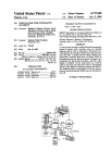
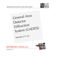
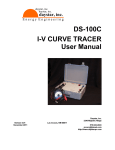
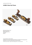
PORTABLE LASER
GONIOMETER
USER MANUAL
CATRA
Henry Street, Sheffield S3 7EQ, UK
Telephone +44(0)114 276 9736
E-mail info@catra.org
Facsimile +44(0)114 272 2151
Web http://www.catra.org
PORTABLE LASER GONIOMETER
CONTENTS
Page
1.
Description
1.1
Principal
1.2
Laser
2.
Safety
2.1
Background
2.2
Laser In User
3.
Assembly and Operation
3.1
Fixturing
3.2
Setting-Up and Calibration
3.3
Battery
Using the Device and Interpreting the Results on the
Scale
4.
2
4
5
7
Appendices:
1 Laser Specification Sheet
1
1. DESCRIPTION
This manual refers to the CATRA Portable laser edge angle measuring device,
which is a small compact unit designed to be held in the hand.
1.1 PRINCIPLE
The design of the laser edge angle measuring device is based on the theory of
light reflection
; Angle of Incidence = Angle of Reflection
Fig 1.1
A simple locating fixture is incorporated into the unit to locate the edge of the
article in the path of a <1mm diameter laser light beam.
A circular scale of 90mm diameter is arranged around the article, where the point
of incidence of the light beam on the component is in the center of the circle.
Depending upon how the scale is used, a virtual full 360° range is available,
allowing measurements of the angle of incidence up to virtually the full 90°.
For a given angle of incidence Ø to the component, the scale reads physically
2xØ.
Fig. 1.2
The arrangement as shown enables the measurement of single or double sided
beveled blades, which makes it particularly suitable for many kinds of cutting
blades, using the correct method of fixturing.
2
3
1.2 LASER
The light source used is a low power visible red (wavelength 635 nm) laser diode
incorporated in a compact housing which allows for safe and easy mounting. This
unit is selected for its compact size and use with low power dc power supply it
consists of a laser diode, lens and driver circuit housed in a metal case with
electrical connections made by flying lead.
Laser Specification :
Type
Wavelength
Max. Output Power
Operating Voltage
Beam Size
Red Laser Diode
635 nm
1 mW
9 V dc
4.5 x 2.5 mm (unfocused) / 1 mm (focused)
By virtue of the front lens, a high quality collimated beam can be produced over a
long distance. The lens position can be adjusted to focus the beam to a spot
using the 'key' provided.
4
2. SAFETY
2.1 BACKGROUND
Laser devices produce beams of intense monochromatic light which can be
potentially hazardous. The degree of hazard depends upon the wavelength of the
light, the power or energy of the beam and the emission duration. The human eye
is the most vulnerable organ as it will tend to focus the light from the beam onto
the retina, thereby increasing the energy density level many times. If the iradiance
of the device is high enough, skin damage can also result from exposure to the
beam.
Laser safety is covered by BS (EN) 60825 which requires products to be classified
according to their levels of radiation. This standard is essential reading for the
users of lasers and also OEM manufacturers. The guidelines of this have been
followed by CATRA in the selection of a laser and the design of the device.
2.2 LASER IN USE
The laser fitted into the measuring instrument as a low output device which omits
visible infrared radiation at 635mm wavelengths
Power 0.9mW / wavelength 635mm
The body of the goniometer carries warning and information labels according to
classification. In this application CATRA certifies the whole assembly of the device
as
Class II
CDRH
Class 2
IEC 825
Fig 2.1
As further safety measures the unit has a momentary switch to enable the beam
and a red indicator to show power and thus laser is on. Thus the beam need only
be on for a short period of time to make a reading of the angles of a component.
Common sense dictates that the user should not stare directly into the beam or its
reflections from highly mirrored surfaces. When the device is used in the correct
manner for measuring sharpened angles then no harmful radiation is projected to
the user. The operator normally only sees a fraction of the energy of the light
when viewing the scale. Eye protection is normally afforded by the aversion
responses, including the blink response.
5
DO NOT:
a)
View the reflections or the beam with optical aids such as telescopes or
similar devices without taking additional precautions.
b)
Offer mirrored or highly reflective surfaces directly into the path of the beam
in an “off-hand” manner as the direction of reflections will not be controlled.
DO:
a)
Place components into the properly designed fixtures which orientate the
reflections onto the scale.
b)
Permit only suitable aware/responsible operators to use the device
c)
Use a pair of appropriate safety spectacles which filter out a certain
percentage of the incident light in the visible infrared range when setting-up
the unit or looking closely for abnormal reflections of non-standard
applications.
3. LASER ASSEMBLY & OPERATION
The unit is supplied complete and ready assembled with the exception that the
battery is not connected. A 9V PP3 battery is supplied and should be connected
as per section 3.3.
3.1 FIXTURING
A single multi-purpose magnetic fixture is fitted to the unit. This is specifically
suited to single/double sided knife blades which should be presented with their
cutting edge up to the datum pins as below.
Fig. 3.1
6
For applications which are not suited to either arrangement the alternative fixturing
may be developed.
7
3.2 SETTING-UP & CALIBRATION
The unit is set-up at CATRA's laboratories and several known, calibrated, ground
edge standards are placed in the fixture to verify that the readings achieved are
within tolerance.
The operate button is a momentary switch and thus the operator must hold a
finger/thumb on this whilst ever an image is required.
3.3 BATTERY
To fit or change the battery, first remove the end cover by unscrewing the 2
screws. Find the standard PP3 press-stud type battery clip and connect with the
correct polarity to the good battery. Slide the battery into its compartment with the
connector facing outwards. Refit the end cover with foam packing where found.
The following diagram shows the goniometer and its main components:
Fig. 3.2
This unit is designed to operate on a standard / high powered PP3 9Vdc battery
e.g. Duracell MN 1604. Alternatively a NiCad rechargeable may be used but this
should be recharged outside the unit.
8
9
4. USING THE LASER RIG AND INTERPRETING RESULTS ON SCALE
When set up properly and using the right fixturing, the goniometer is a means of
obtaining a quick and reasonable accurate measurement of the angle of the
bevelled edge/s of a component. One of the most frequent uses is the scanning of
the ground edge on a knife blade by means of transversing the blade up and
down with the point of beam incidence always at the datum, i.e. the centre of the
scale, to measure the results obtained from the grinding process.
With the full 360o of scale available and the relatively wide beam it is possible to
measure both sides of a double sided component being measured produces many
different reflected patterns on the scale which can be interpreted as indicating the
condition and/or shape of the reflective surface.
If the full circular beam were reflected from a flat true mirror surface then the
reflection produced at the scale would be a circular dot Fig 4.1. Multiple faceted
mirror surfaces would produce a reflection with a shape dependent upon the
shape of the beam incident on it Figs 4.2, 4.3 & 4.4
Fig.4.1
10
Fig.4.2
Fig.4.3
However, the above is not typical of the majority of actual blade type components
manufactured. In practice, components produced by grinding and/or polishing
processes do not behave as perfect mirrors and various other reflected patterns
are observed due to the surface finish imparted by the process.
Of course, the closer the reflection is to the true dot then this is a measure of how
near the surface is to a perfect mirror polish. The most common reflection pattern
seen on the scale is a crescent shape (see figs. 4.4, 4.5 and 4.6) which is the
result of reflections of points of light at compound angles, from the fine surface
marks produced by the abrasive process, on an angled surface.
11
When the abrasive marks are normal to the edge of the blade (fig. 4.6a) and set in
the plane of the beam, then the crescent is symmetrical about the horizontal
plane, but if either the marks are angled or the blade edge is angled from the
normal to the beam, then the crescent turns through an angle depending on which
way the marks are leaning (Fig. 4.6b).
The true reading of the angle normal to a blade edge is achieved when the blade
edge is normal to the beam and up to the datum (ie: centre of scale) and is read
from the scale in the plane of the beam, ignoring the attitude of the crescent (eg:
see figs. 4.5 and 4.6). All other readings not in the plane of the beam are the
result of reflections at compound angles from the reflective surface/s.
The following illustrations show typical projections obtained from the common
types of ground components whose cross-section in the plane of the beam (ie; the
plane of the paper) at the point of incidence is drawn. These are drawn much
simplified for clarity.
Fig.4.4
12
Fig 4.5
13
Fig 4.6
14
One of the advantages of the CATRA device is that both sides of a double edged
component can be measured independently indicating the symmetry of the edge
and also the total included angle if readings of both sides are summed.
Fig 4.7
Other features which are detected by their characteristic reflections are curved or
hollow surfaces which produce a range of reflections as illustrated in Figs 4.3. A
typical result on the scale would be such as shown in Figs 4.8 and 4.9 to where
the reflections from a hollow ground blade span a small band of angles ranging
between the two extremes of the curve.
Similarly, a convex radius on a component which has been polished to blend
cannel to the sides or a honed cutting edge, will produce a band of reflections over
a range of angles. The former will exhibit a band between cannel angle and side
angle and the latter will have a band between the cannel angle and virtually 90 o.
15
Fig 4.8
Fig 4.9
16
These other features are generally less well defined than the predominant angled
surfaces because less light is reflected from them and thus the reflections are of
lesser intensity. Features with low amounts of reflected light are detected more
easily by reducing the surrounding light level, total darkness being the optimum.
Other examples:-
1)
Multi-cannelled edge with polishing and/or honing on tip such as a razor blade
Fig 4.10
17
Appendix I
Technical Specification
635 nm
Beam output
Ellipical
Output power
0.9
Power stability (%)
<5
Wavelength (nm. @ 25°C)
Beam size (mm)
635±5
4x2
Minimum spot size (µm)
Beam divergence (mrad)
Pointing stability (mrad/°C)
Bore sighting(°)
100
0.5
<0.2
<2
Operating voltage (VDC)
Operating current (mA)
Operating temperature (°C)
Storage temperature (°C)
Material
3.0 – 10.0
35
-10 - +40
-40 - +80
HE30 Aluminium
Flying lead length
300 mm
Finish
Anodised
Typical values quoted unless otherwise stated.
Order Information
635 nm Laser diode module
18
Out put
Product Number
Part Number
0.9 mW
58 SDM 1
99 CLASER 0125
LASER DIODE MODULE
19
WIRING DIAGRAM
20