1
JavaSketchpad® compiler
User Manual
Preliminary notice
This is not the documentation for JavaSketchpad but a user manual of my compiler. For the
JavaSketchpad documentation see the website of Key Curriculum Press :
http://www.keypress.com/sketchpad/javasketchpad/
The syntax is that of my on line compiler. The differences from the original syntax of JavaSketchpad
will be given in the text. For a graphical interface, see Key Curriculum Press.
Summary
General syntax p.2
Comments p.2
Code lines p.3
Options p.4
Points p.4
Lines p.5
Circles p.5
Filled items p.6
Measurements p.6
Calculations p.7
Transforms p.8
Captions p.9
Locus p.9
Buttons p.10
Constructions and examples p.11
Arcs p.11
Intersections p.11
Conditional constructions p.12
Using calculates p.13
Import/Export p.14
Appendix p.15
Applet options p.15
Summary of items p.16
Functions not available p.17
Macros p.18
Copyright and licence p.19
General syntax
A JavaSketchpad drawing is built from the Java applet and the drawing script.
Inside an HTML page, it is defined as :
<applet code="GSP.class" codebase="../jsp" archive="jsp4.jar" width="800" height="500">
<param name=Frame value=0>
<param name=MeasureInDegrees value=0>
<param name=Construction value="
…/…
">
alternate display
</applet>
The Java applet is set by the jsp4.jar file
The drawing script by the value of the 'Construction' parameter
Other parameters are used to set background color etc. See appendix.
These applet parameters can't be modifed on line by the compiler.
Alternate display is, in HTML, what is displayed instead of applet when the Java engine is not
available.
Every line in the Construction.value must comply with the original syntax of JavaSketchpad, as
specified by Key Curriculum Press. It is the result of executing the compiler from the source text
which is a different syntax.
Only the source text format is defined here. Allthough very near from the original JavaSketchpad
format, there are big differences.
Comments
Empty lines are ignored.
A comment is a line in curly braces { }
Comments spanning on more than one line should have every line enclosed in curly braces.
The curly braces and the " characters are forbidden inside the comment istself.
Examples:
{
*** This is a comment ***
}
{ and this is a comment spanning }
{ on several lines }
{ blank characters outside the brackets are ignored }
Code line
A code line has the general format
{ <id> } <entity> ( <parameters> … )…( < parameters > …) [<options>…] ;
and ends with a semicolon ;
<id> is the name of the geometric item.
It can be made of letters, numbers or _@§&~|!?=:/^*+.– or space characters and should not begin with
a number or space. The # and $ characters are reserved for future meaning.
Examples :
{A1} {A*}
{A^B}
{A - B}
{@ABC}
The leading numbers and spaces are just ignored, also are the trailing spaces
{1 A} , { 1A } or { A } define the same name A as {A}
{ id } is optional. By default, an automatic name is generated by the compiler.
<entity> is the type of geometric item to generate : Point, Segment, Circle etc.
<parameters> Lists of parameters, separated by comma and in parentheses, depending on entity. For
instance coordinates of a point, center of circle, text of a message etc. :
Point (100,200);
Circle (A, B);
FixedText (20,40,'This is just text');
ShowButton (400,40,'Show')(A,B);
All parameters must be defined before their using. Forward references are prohibited :
In Circle (A, B); points A and B must have been previously defined.
The element id can be just its rank in the element list
{A} Point (100, 200);
{B} Point (100, 300);
Segment (1,2); is the same as Segment (A,B), and is replaced by Segment (A,B) in the
source text by the compiler. This allows to import existing scripts into the compiler.
Of course the generated code is allways Segment (1,2), only syntax understood by the applet.
<options>
Beween square brackets [ ], defines the display options of the element, displayed label, color etc. :
Point (100,200) [label('A'), red];
Note :
1) don't confuse the label (what is displayed) and the name (for referencing in the script)
{A} Point (100,200)[label('B')];
A is the name of the point, for further reference like in Segment (A,…)
B is what is displayed on the drawing.
Of course it is better to put the same, to avoid mistakes …
2) {id} is a comment and ignored by the JavaSketchpad applet. It is meaningfull only for the compiler.
Also comments after the ; may be allowed in the applet, but are forbidden in the compiler. Also several
items on the same line are forbidden.
Point(100,200); { comment} Point (150,300); is illegal
Options
label( 'text' )
Defines the displayed label of a point. Only points may have a label
The text shoul not contain " caracters, or look like HTML tags
The ' shall be doubled ' ' and to emulate a " write ' ' ' '
black, white, red, green, blue, yellow, cyan, magenta preset colors
color( r, g, b)
Any color, r, g, b being red, green and blue parts, from 0 to 255
hidden
Invisible item
thick
Thick line. Only linear items may be thick.
traced
The item leaves a trace when moved. Surface items are forbidden
layer(n)
Drawing layer, increasing for items being above others. n = 1 to 999
Other options, available in JavaSketchpad, are rejected by this compiler.
Points
Points may be defined from scratch or result from geometric constructions.
Point (x,y);
Set a movable point, initial coordinates x, y pixels on the applet
x, y are limited by compiler to visible area 0
y is downward, although y coordinates axis is upward, as it should.
pixel 0 is at top and pixel 499 at bottom !
FixedPoint (x,y); Set a fixed point that can't be dragged with the mouse.
Set a moving point, constrained to stay on object obj which shall be
Point on object (obj, k);
a segment, ray, line, circle or polygon (perimeter).
k sets the initial location (ratio in segment, angle in circle…)
Example:
{AB} Segment (A,B);
Point on object (AB, 0.333333);
The point is constrained to stay on segment AB, initial location is 1/3 of segment from B (!!!)
Other points result from geometric constructions.
Midpoint (segment);
Midpoint of a segment
Intersect (straight, straight); Intersection of two linear items
st
1 intersection point of circle with obj which is another circle or a linear
Intersect1 (obj, circle);
st
nd
item. It is hard to know if the desired point is the 1 or the 2 intersection point
of two circles. Better find other equivallent constructions of that point.
Intersect2 (obj, circle);
nd
2 intersection point with the circle.
And also points from geometric transforms of other points : see "transforms"
Straight lines
Straight lines are defined by two previously defined or constructed points.
They have direction point2
Segment (pointB, pointA);
Defines the segment AB
Ray (pointB, pointA);
Defines the ray AB,starting from A (!!!)
Line (pointB, pointA);
Defines the endless line AB
Parallel (straight, P);
Parallel to the line/segment/ray 'straight', going through P
Has the same direction.
Perpendicular (straight, P);
Perpendicular
from P
to
line/segment/ray
"!$# %'& (*)+,(-# %/. 'straight',
0 13254
Other lines result from geometric transforms of previously constructed segment, ray or line, with the
same type, segment transformed into a segment etc. See 'transforms".
Circles
A circle is defined by the center and one point, or the radius, resulting from previously known points or
measurements.
Circle (center, point);
Circle with given center going through given point
Circle by radius (center, radius);
Circle with given center and given radius.
The radius may be a known segment, a distance measurement or calculated. The compiler rejects a
radius which is obviously not a distance : area, angle, slope or ratio are rejected. Put them through a
calculate, at your own risks for the dumb geometric meaning which may result.
Circles going through three given points should be constructed explicitely.
The center is the intersection point of two segment bissectors, perpendicular from the midpoints.
That is :
{AB} Segment (A,B);
{BC} Segment (B,C);
{M} Midpoint (AB);
{N} Midpoint (BC);
{d1} Perpendicular (AB, M);
{d2} Perpendicular(BC, N);
{O} Intersect (d1, d2);
Circle (O, A);
Intermediate items may be declared [hidden].
The compiler doesn't actually handle macros which would allow to
define all this as "Circumcircle (A, B, C)"
Other constructions in chapter "Constructions and examples ".
Filled items
Circle interior (circle); Defines the disk made of the interior of circle.
It is filled by the default or the given color.
Polygon (A,B,C…Z)
Defines the polygon from the successive vertices,
In order A, B, …Z. At least 3 points, then fills the inetrior of
polygon.
The perimeter couls be used as path for the "Point on object" and "Locus"
The perimeter is not drawn. Use a Circle, or a set of Segment to display it.
These surface items easily play hide and seek and they should use the layer( ) option to define which
are in front of others.
The thick option has no meaning and the traced option would soon fill up the entire plane, so they are
rejected by the compiler.
These items may be copied by geometric transforms.
Measurements and calculations
Measurements display the values, lengths, angles or areas measured on the drawing, but they may
also be used as parameters in further constructions.
Every one has the common parameters :
x, y
location of measurement on the display
'text' text displayed before the measured value
JavaSketchpad allows a suffix after the measured value, this is not presently handled by the compiler.
If they are used just as parameter for further constructions, they may be set [hidden].
Parameter (value, x, y, 'text' ); Defines a constant parameter
Length (segment, x, y, 'text' ); Length of segment, in pixels
Distance (A, B, x, y, 'text' );
Distance between point A and B, in pixels
Perimeter (Poly, x, y, 'texte' ); Perimeter of a polygon
Circumference (circle, x, y, 'text' );
Perimeter of circle
Radius (circle, x, y, 'text' );
Radius of circle, in pixels
Area (obj, x, y, 'text' );
Area in pixel² of object circle, polygon or disk
Angle (A, B, C, x, y, 'text' );
Angle (BA,BC), in radians from
The applet allows displaying angles in radians or in degrees, the compiler sets this option to
"radians" to comply with other angle values which are allways in radians.
+ if anticlockwise from A toward C, – if clockwise.
Slope (straight, x, y, 'text' );
Slope of linear object (tangent of angle from horizontal)
Ratio/Segments (sgmt1, sgmt2, x, y, 'text' );
segm1/segm2 (!!!)
AC/AB (!!!) prefer Ratio/Points to Ratio/Segment if some
Ratio/Points (A, B, C, x, y, 'text' );
points may collapse, then suppressing the segment from drawing.
These measures are typed by the compiler, it is forbidden to use an area or angle as a radius value for
instance. Value types :
Dist
lengths, distances, perimeters
Angle
angles
Area
areas
Ratio
dimensionless values : slope, length ratio
Calc
calculated values or constant parameters
Calculations
The measurements may be used for a calculation :
Calculate (x, y, 'text', 'expr' ) (p1, p2, … pn);
This calculation is performed from the parameters p1 to pn which should be previous measurments or
previous calculations results.
expr defines the calculation in reverse Polish notation.
!"#
!$
!% Every part of expr is
a
Index of a parameter : p1 is named A, p2 is B etc. Hence a maximum of 26 parameters.
An operation + – * / ! or ^, ^ state for exponentiation, ! states for negation
A function @xxxx among
@sin_ @cos_ @tan_ @asin @acos @atan
@sgn_ @abs_ @rond @trnc @sqrt @ln__ @log_
@ln__ is the natural logarithm (base e), @log_ the base 10 logarithm
@rond rounds to nearest integer
@trnc rounds to lowest absolute value integer (toward 0)
@sgn_ -1, 0, 1
note the 4 characters after the @, completed by some '_'
Angles are in radians
The reverse Polish notation consists in stacking successive values and consuming the stack during
operations. Then A+B is written 'AB+' in reverse Polish notation :
Put A on the stack, put B on the stack, sum the two upper values of the stack and put the result on
the stack instead.
A:
B:
A
+:
B
A
A+B
This notation avoids using parentheses and the applet can execute it just by reading from left to right.
'AB+C*' states for (A+B)*C which could also be written as 'CAB+*'
because (A+B)*C = C*(A+B). a last example (A+B)*(C+D) is 'AB+CD+*'
The results of calculation is finally at top of stack, and should be the only thing on the stack.
Non commutative operations / - and ^ result into
'AB/' = A/B, 'AB –' = A – B and 'AB^' = A^B (A exponent B)
Space characters are ignored but for separate two consecutive numbers
For instance '1 2+'
Ambiguous notation 'AB–1…' as A–B then put +1 on the stack, or put –1 on the stack in addition of A
and B is solved by lack of unary minus, in contrary from what is written in JavaSketchpad
documentation, –1 is allways – (operation) then stack 1. Negative values are obtained from x! (for
instance 3.5! is -3.5) or just using substraction instead of addition.
Geometric transforms
Allready constructed items may be copied through a geometric transform.
The copy has the same type as the original object : a segment gives a segment etc.
Reflection (obj, straight);
Objet 'obj' is copied by symetry through line, segment or ray 'straight'
Dilation (obj, P, k);
Dilation (homothecy) centered in P with ratio k (> or < 1, even < 0)
Dilation/SegmentRatio (obj, P, segm1, segm2);
Dilation with center P and ratio segm1/segm2
Dilation/3PtRatio (obj, P, A, B, C);
Dilation with center P and ratio AB/AC.
Same note as Ratio/points, prefer 3PtRatio to SegmentRatio if points may collapse
Dilation/MarkedRatio (obj, P, ratio);
Dilation centered in P, ratio defined by the previous
measurement or calculation 'ratio'
Rotation (obj, P, a);
Rotation centered in P with angle a radians
Rotation/MarkedAngle (obj, P, A, B, C);
Rotation centered in P with angle ABC
Rotation/MeasuredAngle (obj, P, angle); Rotation centered in P with angle previously measured
or calculated
Translation (obj, dx, dy );
Translation of objet by (dx, dy) (dy>0 upward !!!)
VectorTranslation (obj, A, B) Translation by vector AB
Translation/FixedAngle/MarkedDistance (obj, d, a_num)
Translation by previously measured distance d, in direction of angle a from
horizontal.
Translation/MarkedAngle/FixedDistance (obj, a, d_num )
Translation by distance d pixels, in direction of previously measured angle a, from
horizontal.
Translation/MarkedAngle/MarkedDistance (obj, a, d )
Translation of previously measured distance d, in direction of previously measured
angle a, from horizontal.
{d} Distance (P,Q,10,10,' ')[hidden];
{a} Angle (B,A,C,10,10,' ')[hidden];
{O1} Translation/MarkedAngle/MarkedDistance (O,a,d)[label('O''')];
Copy point O as O' in direction defined by angle BAC
And distance equals to PQ
Captions
I addition to measurements, we can also display any text :
FixedText (x, y, 'texte');
Displays text at location x,y on the applet screen
The text object defined by this can be copied by :
PeggedText (P, obj );
The text or measurementt object is 'glued' to point P, the moves
zlong with the point.
ConcatText (x, y, obj, obj, … );
The text/measurements obj are concatenatedand the resulting text
object displayed at location x,y.
Locus
Locus (P, M, path, n);
Draw the locus of point P when the free point M moves along the
given path which should be a segment, ray, line, circle or polygon.
M should be previously declared as 'Point on object', and path should be this
parent object. n is the number of calculated points to draw the locus.
The locus objects can't be copied by a transform and can't be used as parent for "Point on object".
No check is done for point P being constructed from M.
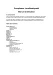
Example : draw a parabola
{A} Point (50,400)[label('(d)')];
{B} Point (600,400);
{AB} Line (A,B);
{F} Point (300,320)[label('F')];
{M} Point on object (AB, 0.8)[label('M')];
{FM} Segment (F,M);
{H} Midpoint (FM)[hidden];
{m} Perpendicular (FM,H);
{d} Perpendicular (AB,M);
{P} Intersect (m,d)[label('P')];
{parab} Locus (P,M,AB,100);
The drawn locus changes in real time when moving the base points A,B and F
Moving point M shows how the parabola is drawn.
Drawing the locus of a segment/ray/line is les usefull as it just draws the segment for every position.
Envelope of line is visible but in a mess of lines.
Here the enveloppe of m is the same parabola, Locus (m,M,AB,100); shows this envelope but
draws 100 lines m !
When a locus has asymptotes, spurious lines may appear. If n is large enough, these lines are just …
the asymptotes.
Buttons
Buttons trigger actions as show/hide parts of the drawing, or animate the construction.
Like measurements, they allways have the position x,y and the caption parameter.
HideButton (x, y, 'text' )(obj, obj, … );
All the given objects are hidden.
ShowButton (x, y, 'text' )(obj, obj, … );
[hidden].
All the given objects are displayed, even if declared
MoveButton (x, y, v, 'text' )(A, A', B, B', … ); The free points A', B' … are move toward the
corresponding points A, B … at a speed v pixels per frame.
(care of the order : destination, point …)
AnimateButton (x,y,'text') (A, Pa, B, Pb, …) (va, vb, …) (fa, fb, …) (ma, mb, …);
The free points A, B, … are moved along corresponding paths Pa, Pb, …
At speeds va, vb, … Points should be 'on object' and move on that object.
fa, fb, … and ma, mb, … are flags that define the moving fashion
f = 0 indefinite repeat, f = 1 once
m = 0 anti-clockwise on a circle, back and forth on a line
m = 1 clockwise on a circle, forth only on a line
SimultaneousButton (x,y,'text')(obj, obj, … ); All the buttons obj are acted. This allows to declare
some {v} ShowButton [hidden] and some {h} HideButton [hidden], then a
SimultaneousButton (v,h) simulateneously shows objects declared in v and hides
the objects declared in h.
Constructions and examples
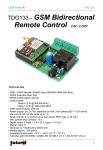
Drawing an arc
{ ================ }
{ *** Draw arc *** }
{ ================ }
{A} Point (100,200)[label('A')];
{B} Point (150,300)[label('B')];
{C} Point (130,100)[label('C')];
{BC} Segment (B,C)[hidden];
{M} Point on object (BC,0.3)[hidden];
{P} Rotation/MarkedAngle (B,A,B,A,M)[hidden];
{arc} Locus (P,M,BC,100);
{Ab} Ray (B,A);
{Ac} Ray (C,A);
!"# $%'&"()* +, -).+')/(01)&2-34 , &, &, 5&2
smaller arcs. For instance to draw a semi-circle.
{ ======================== }
{ *** Draw half circle *** }
{ ======================== }
{A} Point (100,100)[label('A')];
{B} Point (180,200)[label('B')];
{AB} Segment (A,B)[hidden];
{O} Midpoint (AB)[label('O')];
{ pi/2 }
{H} Rotation (B,O, 1.5707963267948966)[hidden];
{s1} Segment (A,H)[hidden];
{M1} Point on object (s1, 0)[hidden];
{P1} Rotation/MarkedAngle (A,O,A,O,M1)[hidden];
{arc1} Locus (P1,M1,s1,100);
{s2} Segment (B,H)[hidden];
{M2} Point on object (s2, 0)[hidden];
{P2} Rotation/MarkedAngle (B,O,B,O,M2)[hidden];
{arc2} Locus (P2,M2,s2,100);
6728*
0+9&"()2:&"()*-);, <, *
<4 ).*
)34 0<)=?>A@CBD'EF= GAHIJKLFMNOPQKSRTOPUCV
Drawing a sector or half disk is not so easy : draw a large enough amount of vertices of a polygon…
Other intersection point
When a line d going at A intersects a circle going at A with center O, the other intersection point
should not be defined using Intersect1/2 because it won't be the right one : from the Murphy's law, it
will be A again ! The trick is to construct otherwise :
{O} Point (100, 200)[label('O')];
{A} Point (50,150)[label('A')];
{D} Point (400, 30);
{d} Line (A,D);
{C} Circle (O,A);
{ *** second intersection : *** }
{m} Perpendicular (d, O)[hidden];
{B} Reflection (A, m)[label('B')];
nd
And similarily for the 2
intersection of two circles
Intersection with a ray
The choice Intersect1/Intersect2 with a line can be handled as it depends only on the definition of the
line. Line (A,B) is in direction B toward A, Intersect1 is the first and Intersect2 the second along this
direction, that is Intersect1 is the entry point into the circle and Intersect2 the exit point.
Similarily with a Ray(A,B) starting from B, in direction B toward A and a Segment (A,B) B toward A.
Drawing horizontal/vertical lines
Just move the base point through a translation by dx, 0 or 0,dy
{ horizontal from A }
{A.} Translation (A,100,0)[hidden];
{d} Line (A,A.);
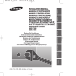
Conditional constructions
For instance to restrict a point M in the half plane defined by line (d) and point P
The perpendicular to (d) from M intersects (d) in I. Line PM intersects (d) in J (may be at infinity)
Rays IM and JP intersect (in M) only when P and M in the same half plane from (d). Continue the
construction from this intersection point instead of M.
{ line (d) }
{A} Point (100,10);
{B} Point (150,400);
{d} Line (A,B);
{P} Point (200,100)[label('P')];
{M} Point (300,200);
{ test }
{q} Perpendicular (d,M)[hidden];
{I} Intersect(d,q)[hidden];
{PM} Line (P,M)[hidden];
{J} Intersect (d,PM)[hidden];
{Jp} Ray (P,J)[hidden];
{Im} Ray (M,I)[hidden];
{M.} Intersect(Jp, Im)[label('M'),red];
{ use M. }
{C} Point (160,300)[label('C')];
{CM.} Segment(C,M.);
(points have been moved in the figure, and rays made visible in green)
Segment CM etc. exist only when P and M on the same side of (d) : otherwise M and CM disappear
and also all further constructions wich rely on 'M.' .
The same trick (intersection with rays or segments) could be used in similar cases to ensure what we
construct really satisfy the conditions of the problem. Conversedly, we could extend segments into
lines to handle more general cases.
Some other possibility of conditional drawing is by using Calculate, and for instance @sgn_ or @abs_
to get 0 values if some condition.
Using calculate
All the classical constructions with compass and straightedge are obtained from lines and circles
drawn by basic functions. The Calculate function allows to go beyond these constructions, for
instance construct a regular polygon with 7 sides or trisect any angle etc.
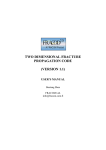
As example, let's show the Morley's theorem, which requires to trisect angles of any triangle.
{ *** Morley triangle *** }
{ *********************** }
{A} Point (100,400)[label('A')];
{B} Point (400,400)[label('B')];
{C} Point (200,100)[label('C')];
{AB} Segment (A,B);
{BC} Segment (B,C);
{CA} Segment (C,A);
{ measure angle A.. and calculate A/3.. }
{a} Angle (B,A,C,10,10,' ')[hidden];
{a/3} Calculate (10,10,' ','A3/')(a)[hidden];
{b} Angle (C,B,A,10,10,' ')[hidden];
{b/3} Calculate (10,10,' ','A3/')(b)[hidden];
{c} Angle (A,C,B,10,10,' ')[hidden];
{c/3} Calculate (10,10,' ','A3/')(c)[hidden];
{ draw trisectrix }
{B1} Rotation/MeasuredAngle (B,A,a/3)[hidden];
{AB1} Ray (B1,A);
{B2} Rotation/MeasuredAngle (B1,A,a/3)[hidden];
{AB2} Ray (B2,A);
{C1} Rotation/MeasuredAngle (C,B,b/3)[hidden];
{BC1} Ray (C1,B);
{C2} Rotation/MeasuredAngle (C1,B,b/3)[hidden];
{BC2} Ray (C2,B);
{A1} Rotation/MeasuredAngle (A,C,c/3)[hidden];
{CA1} Ray (A1,C);
{A2} Rotation/MeasuredAngle (A1,C,c/3)[hidden];
{CA2} Ray (A2,C);
{ draw Morley triangle now }
{D} Intersect (AB1,BC2)[label('D')];
{E} Intersect (BC1,CA2)[label('E')];
{F} Intersect (CA1,AB2)[label('F')];
{t} Polygon (D,E,F)[cyan];
Triangle DEF is equilateral for any ABC triangle.
Import/Export
Importing a source by copy/paste from an existing script is nearly automatic, just take care of
comments and item names (ids).
Ensure there are no multi-lines comments nor comments inside comments, nor inside or after the code
line.
A name should be explicitely defined for all items in the script.
The compiler generates a default name if none is given, but this could lead to double definitions when
modifying the script.
Also some JavaSketchpad functions are ignored, and rejected by the compiler.
Importing as source a script allready translated by the compiler allways work, by construction.
The primary aim of the compiler is to generate on the fly an applet in the same page as the compiler,
or automatically exported into a dynamically created page of my site.
The generated script could as well be exported by copy paste from the "translated" area of the
compiler into your own web page, just put it inside a suitable <applet> </applet> tag.
You should then download the JavaSketchpad applet from Key Curriculum Press :
http://www.keypress.com/sketchpad/javasketchpad/
to be able to view it from your own pages.
At last the source may be saved by copy/paste from the "source" text area into any text file, but as
being compatible with the translated script, could be regenerated from the script that is available from
the "view source" of the web page.
You may also use the online compiler to export the drawing itself as a static image from 'print Screen'.
Appendix
Applet options
Alltough they can't be modified by the online compiler, these options may be used in your own pages.
Background color : default = grey 200 200 200
<param name=BackRed value=0>
<param name=BackGreen value=255>
<param name=BackBlue value=0>
Frame : 0 no frame, 1 frame, 1 pixel wide, solid
<param name=Frame value=0>
Style of labels :
<param name=LabelFont value=…> default = Helvetica
<param name=LabelSize value=6…100> default = 12
<param name=LabelBold value=0/1> default = 1
<param name=LabelItalic value=0/1> default = 0
Style for buttons : idem ActionFont, ActionSize, ActionBold, ActionItalic
default = TimesRoman 14 0 0
Style for measurements and captions : idem
MeasureFont, MeasureSize, MeasureBold, MeasureItalic
default = Helvetica 10 0 0
Angle measurments :
MeasureInDegrees 0 in radians (default), 1 in degrees. To reuse a measurement in degrees,
you must convert it into radian by a Calculate.
DirectedAngles
!"#
!$&%'()*+ ,
At last, the size of applet is defined by the <applet> tag itself :
width=xxx height=yyy
The parameter codebase="../jsp" defines the location where is stored the Java applet in the directory
tree of the site.
The remaining (code="GSP.class" archive="jsp4.jar") is defined by the specification of
JavaSketchpad.
Summary of items
Point (NUMX, NUMY)
FixedPoint (NUMX, NUMY)
Midpoint (SEGM)
Point on object (STRAIGHT|CIRCLE|POLY, NUMB)
Intersect (STRAIGHT, STRAIGHT)
Intersect1 (STRAIGHT|CIRCLE, CIRCLE)
Intersect2 (STRAIGHT|CIRCLE, CIRCLE)
Segment (PNT, PNT)
Ray (PNT, PNT)
Line (PNT, PNT)
Perpendicular (STRAIGHT, PNT)
Parallel (STRAIGHT, PNT)
Polygon (PNT, PNT, PNT, ETC)
Circle (PNT, PNT)
Circle by radius (PNT, SEGM|DIST|CALC)
Circle interior (CIRCLE)
Reflection (OBJ, STRAIGHT)
Dilation (OBJ, PNT, NUMB)
Dilation/SegmentRatio (OBJ, PNT, SEGM, SEGM)
Dilation/3PtRatio (OBJ, PNT, PNT, PNT, PNT)
Dilation/MarkedRatio (OBJ, PNT, CALC|RATIO)
Rotation (OBJ, PNT, NUMB)
Rotation/MarkedAngle (OBJ, PNT, PNT, PNT, PNT)
Rotation/MeasuredAngle (OBJ, PNT, ANGLE|CALC)
Translation (OBJ, NUMB, NUMB)
VectorTranslation (OBJ, PNT, PNT)
Translation/FixedAngle/MarkedDistance (OBJ, DIST|CALC, NUMB)
Translation/MarkedAngle/FixedDistance (OBJ, ANGLE|CALC, NUMB)
Translation/MarkedAngle/MarkedDistance (OBJ, ANGLE|CALC, DIST|CALC)
Length (SEGM, NUMX, NUMY, STRING)
Angle (PNT, PNT, PNT, NUMX, NUMY, STRING)
Perimeter (POLY, NUMX, NUMY, STRING)
Circumference (CIRCLE|INTERIOR, NUMX, NUMY, STRING)
Radius (CIRCLE|INTERIOR, NUMX, NUMY, STRING)
Area (CIRCLE|INTERIOR|POLY, NUMX, NUMY, STRING)
Slope (STRAIGHT, NUMX, NUMY, STRING)
Distance (PNT, PNT, NUMX, NUMY, STRING)
Ratio/Segments (SEGM, SEGM, NUMX, NUMY, STRING)
Ratio/Points (PNT, PNT, PNT, NUMX, NUMY, STRING)
Calculate (NUMX, NUMY, STRING, EXPR), (MEASURE, ETC)
Parameter (NUMB, NUMX, NUMY, STRING)
ShowButton (NUMX, NUMY, STRING), (OBJ, ETC)
HideButton (NUMX, NUMY, STRING), (OBJ, ETC)
MoveButton (NUMX, NUMY, NUMB, STRING), (PNT, FREE, ETC2)
AnimateButton (NUMX, NUMY, STRING), (FREE, PATH, ETC2), (NUMB, ETC),
(FLAG, ETC), (FLAG, ETC)
SimultaneousButton (NUMX, NUMY, STRING), (BUTT, ETC)
Locus (POINT|STRAIGHT, FREE, PATH, NUMB)
FixedText (NUMX, NUMY, STRING)
PeggedText (PNT, CAPT|MEASURE)
ConcatText (NUMX, NUMY), (CAPT|MEASURE, ETC)
Functions of JavaSketchpad not available in compiler
Several functions of JavaSketchpad are ignored (= rejected) by the compiler.
It is forbiden to use the image functions :
Image, ImageOnPoint, ImageBetweenPoints as well as the image('url') option, this in the context of
on line usage for safety reason (no outside url, no local images available).
Functions on coordinate systems Origin&Unit UnitCircle AxisX AxisY PlotXY UnitPoint are not
available, to simplify the compiler, as well as aliases DriverPoint and PolarTranslation.
Option auto is rejected, to insure manual start of animations, also are options for text styles :
bold italic plain size(number) font(string) justifyLeft justifyRight justifyCenter
(just to simplify the compiler) and option suffix(string) is rejected for the same reason.
A more strict check of parameter types is performed by the compiler, rejecting constructions that
would go through JavaSketchpad with a doubtfull result or that would be ignored as meaningless.
Macros
The macros and control structures do not exist in this release of the compiler.
The preview syntax could be :
Macro definition :
#define <name> (type, type, …);
<body>
#end
call :
{id} name (para, para, …);
Inside the body, the syntax is normal lines except that id names are :
- As parameter, #1, #2 … formal parameters, being replaced by real parameters when expanding.
- As id, replaced by $*id with * being the number of macro calls
The macro returns the last object created., display options apply to last object only.
Example :
#define Bissector (pnt, pnt);
{$s} Segment (#1,#2)[hidden];
{$m} Midpoint ($s)[hidden];
Perpendicular($s,$m);
#end
The call :
{d} Bissector (A,B)[blue];
{e} Bissector (C,D)[red, thick];
is then expanded into :
{$1s} Segment(A,B)[hidden];
{$1m} Midpoint ($1s)[hidden];
{d} Perpendicular ($1s, $1m)[blue];
{$2s} Segment (C,D)[hidden];
{$2m} Midpoint ($2s)[hidden];
{e} Perpendicular($2s,$2m)[red, thick];
which is then translated as usual by the compiler
The source of macro definitions is not included in the translated script.
Control structures
Allowed only inside macro definitions
#if exp exp = test on constant value or parameter types (no test on variable or measurement)
#if #1=PNT test if paramètre #1 is a Point
#if #1=3
test if paramètre #1 is nomber 3 (constant, not the result of a measurement
as this just can't be done at compile time.)
#else
#endif
#for $i = parameter list or $i = value to n by step. value n and step could be #p constants
#endfor
Copyright and licence
JavaSketchpad® is the property of Key Curriculum Press Inc, its using is granted under the licence
conditions defined on their web site :
http://www.keypress.com/sketchpad/javasketchpad/
The compiler is my own property. I grant you the free usage of this compiler from my Web site
http://chephip.free.fr/ in order to generate your own drawings, to be published on my site or for your
own use. In the latter case, you should get JavaSketchpad by yourself from Key Curriculum Press Inc.
This program is distributed "as is" and without any warranty for damages, loss of data or failure of the
program. Use it under you own liability.
Version 1.0 (creation) Jun 2006 Copyright Philippe Chevanne