1
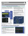
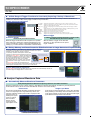
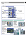
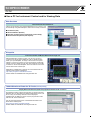
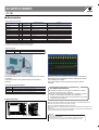
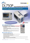
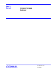
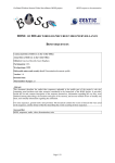
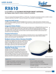
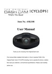
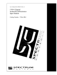
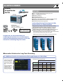
SCOPECORDER
701210
VIEW
RECORDERS
ScopeCorder
DL750
FEATURES
● Up to 16 analog channels and 16-bit logic input
● Up to 1 GigaWord total memory
● GIGAZoom function
● DualCapture function
● 10.4-inch SVGA color TFT LCD
● 10 MS/s, 12 bits A/D resolution, 2-channel isolated module
● Floppy disk, ZIP disk and PC card drives available
● 20-GB internal hard drive (optional)
DL750(701210)
355 × 250 × 180 mm 9 kg
(13.98 × 9.8 × 7.09inch),
(Main unit and eight 701250 modules)
★
Safety Standards ; EN61010-1
Emission ; EN61326 Class A
Immunity Standard ; EN61326
Leading-Edge Mounting Technology and ASICs
Reduce the Size of 2-Channel Modules
■ High-Speed (10 MS/s), 12-Bit Isolated Module (701250)
Broad bandwidth (3 MHz) and high accuracy (0.5%) inputs
■ High-Speed (1 MS/s), 16-Bit Isolated Module (701251)
High resolution inputs combined with high-sensitivity (1 mV/div)
■ Temperature/High-Precision Voltage Module (701265)
100 Hz frequency range, high-accuracy (0.08%) voltage measurements,
and an ultra high-sensitivity range value (100 µV/div)
Additional input modules will be added to the lineup in the future.
ScopeCorder: A new measurement tool
combining the functions of an oscilloscope for
capturing instantaneous phenomena, and a data
recorder for monitoring long-term trends
Modules
701251
701250
701265
■ Innovative Solutions for Long-Term Recording
● GIGAZoom Function for Instantaneous Full-Length Display of 1 GW of Data
1 GW memory for full-length display and instantaneous
zooming (to user-specified size)
A large-scale, high speed
ASIC was created to give
the DL750 the ability to
show the entire 1 GW of
data on the display in real
time
Two zoom windows are
available for displaying up
to 500 MW of data.
Zooming can be done in
real-time or after data
recording has stopped.
Roll-mode view
Maximum Recording Time
Sample Rate
Seconds
10 MS/s 100 seconds
Minutes
Hours
Days
1.67
0.028
0.001
10 minutes
0.167
0.007
9000 150 minutes
2.5 hours
0.10
72000
1200
20 hours
0.83 day
1 kS/s
864000
14400
240.0
10 days
200 S/s
2592000
43200
720.0
30 days
1 MS/s
100 kS/s
10 kS/s
600
■ Amount of time data can be recorded with 1 GW memory
SCOPECORDER
DL750
FUNCTIONS
● DualCapture: A Powerful Tool for Durability Test Data Analysis
Simultaneous High-Speed and Low-Speed Recording Using DualCapture
Using DualCapture, you can now record your trend data with a
slow sampling speed and still be able to capture the transient
phenomena with a faster sampling speed.
■ Integration of a High-Speed Sampler (Oscilloscope) and
Low-Speed Sampler (Recorder) in a Single Unit
High-speed sampler: Trigger on abnormal high-speed
phenomena
Low-speed sampler: Roll recording (trend recording)
■ Separate Memory Management for Each Sampler
Maximum memory for low-speed sampler: 100 MW
Maximum memory for high-speed sampler: 10 kW × 100
screens
■ High-Speed Sampling Triggered Only by Abnormal
Maximum 100 MW
Phenomena Occurring During Long-Term Observation
(Low-Speed Sampling)
Effective for separately capturing data at high speed during
measurements.
■ Long Memory Equivalent to 1 Teraword
To acquire many hours of data at the higher sampling rate
(10 MS/s) would require Terawords of memory
(8 hr-240 hr) × 60 min × 60 sec × 10 MS/s × 16 channels
= 4.6-138 TW
During durability testing, it is necessary to monitor the longterm trends of your data as well as capture the high speed
transients that might occur. This presents a challenge as trend
data is usually recorded at a slower sampling speed that might
miss the transient phenomena. To meet this challenge, the
DL750 offers the DualCapture function.
10 kW
This is the limit for
50 kS/s
10 kW
User-specified
captured
screen and the
corresponding
time are
displayed.
Phenomena can be
accurately assessed
at 10 MS/s
Phenomena can be
accurately assessed
at 10 MS/s
Same
phenomenon
The waveform shown above was captured at a sampling rate
of 50 kS/s. The occurrence of noise can be confirmed in the
graph, but the time resolution is too low to capture the
waveform accurately.
Maximum 100
phenomena
With DualCapture, the user sets triggers for capturing sudden
phenomena. Up to 100 phenomena can be collected in a memory
length of 10 kW at a maximum sampling rate of 10 MS/s.
■ Accurately Measure and Display Complex Signals
● Capturing Signals Using the Longest Memory Capacity Ever
For Accurately Capturing Complex Signals or Long Waveforms
The DL750’s standard memory capacity is 50 MW (2.5 MW per
channel). This can be expanded (optional) to as much as 1 GW
(50 MW per channel).
■ Benefits of GigaWord Recording
You can record data for 10 days (1 day/div) on the main screen, while
displaying 1-second recordings (100 ms/div) in real time on the zoom
screen. The large memory capacity lets you capture all of your data
while still maintaining a sample rate fast enough to see any abnormal
phenomena.
■ Efficient Memory Use
Sufficient memory length is available even when 16 channels are used,
so you can conduct extended observations on multiple channels (2.5
MW per channel with standard memory, 50 MW per channel with
maximum memory).
Multi-Channel 2-Location Zoom Function
SCOPECORDER
DL750
VIEW RECORDERS
● A Wide Range of Trigger Functions for Accurately Capturing a Variety of Waveforms
Having a wide range of triggers is of course very useful for obtaining stable observations of variety of different waveforms. In
addition, the GUI menu makes setting trigger conditions easy and intuitive.
Simple and Enhanced Triggers
Edge trigger: Set a regular edge trigger
A ➝ B (N): Triggers the n-th time that condition B goes true after condition A has gone true.
A Delay B: Triggers if condition B goes true after condition A has gone true and an interval at least
equal to the delay setting has elapsed.
Edge on A: Activates an edge trigger on another input during the interval when trigger condition
A is true.
OR:
Triggers when any one of the individual channel conditions set with the patterns goes true.
B > TIME:
Triggers when the pulse width is longer than the set time
B < TIME:
Triggers when the pulse width is less than the time
B TIME OUT: Triggers when a preset time-out time is reached
Period:
Triggers when a preset waveform frequency condition goes true.
Window:
Triggers when a trigger source enters or leaves a level set by two points
Manual Trigger
Action-On Trigger
In Addition to Simple and Enhanced Triggers, a Trigger Can Be
Activated Manually with Press of a Button.
Automatically Save Measured Data
When this trigger is activated, the DL750 performs a specified
action each time a waveform is captured and displayed on the
screen. This feature is useful for saving data automatically and
reliably (e.g., for data collection in automated, continuous tests).
With this feature, a trigger can be executed
whenever you like, separate from the preset
trigger conditions.
● History Memory and Smart Search for Effective Access to Large Amounts of Captured Data
History Memory and History Search (Zone Search)
Occasionally, you may capture an abnormal waveform and then have it quickly
disappear from the display as new data is acquired.
It is not always possible to manually Start and Stop data
acquisition to catch the abnormal waveform and have it
Abnormal waveforms in the
displayed.The History Memory function was designed for
specified zone are extracted.
such situations. It divides long memory into a number of
blocks and automatically stores up to 2000 previously
captured waveforms. This means you can reliably
Zone
save displayed waveforms to memory even when there
setting
are phenomena for which trigger conditions cannot be Up to 2000 screens of
set.
History Memory data.
The Zone Search function lets you define zones on
the screen, and find all previously captured waveforms that either pass or don’t
pass through the user-defined zone. Up to four zones can be defined.
View all stored waveforms simultaneously
Find all waveforms passing through zones
Search (Edge Search) and Zoom
The Edge Search counts rising and falling edges in the captured data. It automatically searches for
the desired edges and displays them on a zoom screen.
■ Analyze Captured Waveform Data
● Automatically Measure Waveform Parameters
Easily Reading Measured Waveform Frequency, Rise Time, and Other Parameters
Waveform parameters such as voltage, frequency, and RMS are measured automatically. In addition to general parameter
measurement function, the DL750 comes standard with functions such as the following:
Pulse Count
Single-Cycle Mode
This function automatically calculates and displays the pulse
count for an input signal in a range defined by cursors. It is
useful for measuring rotation pulse counts of equipment like
stepping motors, for
tracking error signal
counts for optical
discs and other
devices, and for
counting encoder
output pulse counts.
In this mode, the DL750 determines a cycle, then calculates
items pertaining to the voltage axis and surface area in that
cycle. Range settings can be used to obtain accurate singlecycle RMS and average value measurements.
Example of pulse count settings
SCOPECORDER
DL750
Linear Scaling
GO/NO-GO Judgment
Convert Measured Voltage Values to Physical Values for Direct Reading
This function automatically performs the
following calculation based on a scaling
coefficient A and offset B: Y = AX + B (X is a
measured value and Y is the scale value)The
results of this calculation are reflected in
cursor measurement values and waveform
parameter measurement values. In addition,
user-determined scale values can be defined
for any two measurement, P1 and P2.
Scale value
y=ax+b
P2
P2:Y
P1:Y
P1
P1:X
P2:X
Measurement range (voltage)
Measurement value
(voltage)
Automatic Waveform Determinations
With this function, the user specifies a zone or
waveform parameter for a measured waveform.
The measurement signal is evaluated and a
specified action is performed automatically
based on the evaluation. Available actions
include outputting a screenshot to a specified
destination, saving waveform data to a specified storage medium,
sounding a buzzer, and sending email.
User-Defined Math Function (with the /G2 Option Only)
Perform Complex Calculations
The DL750 comes standard with basic arithmetic operations (addition, subtraction, multiplication,
division), FFT (power spectrum), and phase shifting (calculating a phase shift between channels).
For more flexible and complex calculations, an optional user-defined math function package is
available. With this option, you can define up to eight different formulas using a wide range of
functions, including a triangle function, differentiation, integration, square root, digital filter, and
seven different FFT functions.
You can also specify the results of a calculation as a parameter in another formula. With these
capabilities, the DL750 makes it easy to perform complex calculations that, in the past, could only
have been done by loading data onto a PC.
■ Display and Data Recording Functions
Real-Time Hard Drive Recording (with the /C8 Option Only)
Recorder-Like Real-Time Data Recording over Extended Periods
Memory Backup Function
Protects Your Data Even If the Power Supply Goes Out
With the optional internal hard drive,
you can record measurements to the
hard drive in real time. This makes it
easier to manage and analyze data
using PCs and other tools.
Maximum data capacity:
1 GW
Maximum sampling rate: 100 kS/s
(using 1 channel only)
This function backs up about 10 hours of
data saved to the acquisition memory
immediately prior to power loss. Memory
backup helps you avoid losing important
data even if the power supply is unstable
and gets cut off. (Backup time varies
according to the usage environment. Four
AA batteries are required for memory
backup.)
Snapshot Function
X-Y Display Function
Enables On-Screen Waveform Comparisons
Display an Overlay of up to Four X-Y Displays
Using the snapshot function, you can keep the currently displayed
waveform with the touch of a button. Snapshots are useful for
comparing a reference waveform with an input waveform. In
addition, snapshots can be saved to and loaded from the storage
media.
This function lets you display multiple X-Y plots together, making
relative phase comparisons easy. The X-Y display function is a
powerful tool for applications such as evaluating DC motors based
on a Lissajous waveform.
All-Channel Setup Menu
Wide Waveform Display
Quickly View the Setup of All Channels
This menu lets you review and modify all of the channel setups from
a single screen display. Parameters such as voltage axis sensitivity,
screen scale settings, and linear scaling can be configured for each
channel.
Increase the Viewing Area of Display
With the SVGA color TFT liquid crystal display, the number of
display pixels has been greatly increased. For wide waveform
display, set the resolution to 750 × 512 pixels.
SCOPECORDER
DL750
VIEW RECORDERS
■ Complete Connectivity
■ Ethernet (optional)
Supports 100BASE-TX and
10BASE-T
■ Internal hard drive (optional):
20 GB (FAT32)
■ GP-IB
■ Drive (select one of three options)
• Floppy
• Zip® (250 MB/100 MB)
• PC card (Flash ATA card)1
(16 MB to 5 GB)
■ Video Out (SVGA)
Outputs a video signal so
waveform can be viewed on an
external monitor
■ SCSI interface
■ SERIAL (RS232)
■ USB—PC jack (complies with USB Rev.
1.1)
■ USB peripheral jacks1
■ Logic input (8 bits × 2)
■ GO/NO-GO I/O
External start/stop
■ Trigger output/external clock input (switch)
Outputs TTL level trigger signals
External clocks as fast as 1 MHz can be
used (with 701250 or 701251).
■ External trigger input
1 Ask for information on compatible products.
Ethernet (Optional)
USB
• Connecting to a PC
• Connecting to a PC
(Supported operating systems: Windows 98 SE, Windows
2000 Pro, Windows Me)
Just as for RS232 and GBIB, you can write your own
custom programs in Visual
C++ 6.0 or Visual Basic 6.0
to control the DL750 through
a USB interface.
PC communications are
made easy with the
Waveform Viewer and
Wirepuller software programs.
■ Web Server and
FTP Server
The DL750 has a
variety of server
functions that let you
perform remote
controls or download
waveform data and
screen images onto a
PC. You can also
access the DL750
through the Internet
Explorer. Just as for RS232 and GB-IB, you can write your
own custom programs in Visual C++ 6.0 or Visual Basic 6.0
to control the DL750 through a USB interface.
• Connecting USB Peripheral Equipment
USB keyboards and USB printers can be directly connected
to the DL750.
IMAGE SAVE Key and Thumbnail Screen Images
Simply press the IMAGE
SAVE key to save image
data to a CompactFlash card
or other storage media. The
saved image data (PNG,
JPEG, BMP, or PostScript
format) can then be
displayed on the DL750’s
screen as thumbnails. The
PRINT key lets you output
images to the DL750’s buildin printer, a USB printer, or a
network printer.
Thumbnail display
SCOPECORDER
DL750
■ Use a PC for Instrument Control and for Viewing Data
Web Services
Turn Your DL750 into a Web Server
The DL750 can function as an independent Web server. Connect to your
DL750 directly using Internet Explorer, and access a variety of services.
■ File Transfer (FTP)
■ Waveform Monitor (Monitor)
■ Execution of Simple Control Commands (Control Script)
■ Waveform Data Acquisition (Data Capture)
Wirepuller
Control Your DL750 and Monitor Waveforms through a PC
With the Wirepuller software program, you can use your PC to
control the DL750 through an Ethernet, USB, or GP-IB interface.
When you open Wirepuller, an image of the DL750’s front panel
appears on your PC’s monitor. You can control the DL750 through
actions on the PC display. You can also view waveforms on the PC.
In addition to the DL750, Wirepuller also works with DL1700 series
and DL7000 series oscilloscopes.
Wirepuller is available free of charge. You can download it at the
following URL (requires registration):
http://www.yokogawa.com/tm/Bu/DLsoft/wire/
Further details are available at the Yokogawa web site.
700919 Waveform Viewer for DL Series (Sold Separately)
Display Waveform Data Files (WVF Files) Captured with the DL750 on Your PC
The Waveform Viewer software program lets you display waveform
data files (the .wvf File extension) captured with the DL750 on your
PC. As many as 24 analog waveforms can be displayed
simultaneously. In addition to the DL750, this program also works
with other DL series instruments.
You can download a trial version of the Waveform Viewer for DL
Series at the following URL:
http://www.yokogawa.com/tm/Bu/700919/
Further details are available at the Yokogawa web site.
SCOPECORDER
DL750
VIEW RECORDERS
SPECIFICATIONS
Basic Specifications
● Input
Type
Slots
Logic inputs
● Horizontal
Maximum record length
Time axis accuracy1
Sweep time
● Acquisition modes
Normal
Envelope
Box average
Averaging
Roll
● Triggers
Modes
Plug-in module (Each unit has a build-in A/D converter)
8
16 (8 bits × 2)
2.5 MW/CH, 50 MW total (standard)
10 MW/CH, 250 MW total (with /M1 option)
25 MW/CH, 500 MW total (with /M2 option)
50 MW/CH, 1 GW total (with /M3 option)
±0.005%
500 ns to 5 sec/div (1/2/5 steps), 10 sec/div,
20 sec/div, 30 sec/div
1 to 10 min/div (1 min steps), 12 min/div,
15 min/div, 30 min/div
1 to 10 h/div (1 h steps), 12 h/div
1 day/div, 2 days/div, 3 days/div
Maximum sampling rate: 10 MS/s
Holds peak value at maximum sampling rate,
regardless of time/div setting
Increases A/D resolution up to 4 bits (up to 16 bits)
Number of averagings: 2-65,536 (2n steps)
100 msec/div or less
AUTO, AUTO LEVEL, NORMAL, SINGLE, SINGLE
(N), LOG
CH1 to CH16, LINE, EXT, LOGIC_A, LOGIC_B, TIME
Simple trigger source
Slope selection CH1 to CH16: Rise, fall, rise-fall, EXT (external
trigger input), LOGIC_A, LOGIC_B: Rise, fall
Time: Date (year/month/date), hour (hours/
minutes), time interval (1 minute to 24 hours)
Enhanced trigger source CH1 to CH16, LOGIC_A, LOGIC_B
Enhanced trigger type A ➝ B (N), A delay B, B > Time, B < Time, B Time
Out, Period, Windows, OR, Edge On A
● Screen updating rate
Maximum 30 screens/sec for a single waveform
1: Typical operating conditions:
Ambient temperature of 23°C ±5°C, ambient humidity (RH) of 55±10%
Display
Display
Effective screen size
Resolution
Waveform display pixels
10.4-inch color TFT LCD
211.2 mm × 158.4 mm
800 × 6001
650 × 512 (in normal waveform display mode)
750 × 512 (in wide waveform display mode)
Display modes
Split Single, dual, triad, quad, octal
Zoom Main, Main & Z1, Main & Z1 & Z2, Main & Z2, Z1 Only, Z2
Only, Z1 & Z2 (Z1 and Z2 are abbreviations for
zoom area 1 and zoom 2, respectively)
XY Single Mode (X is fixed, Y is set by user), Quad
Mode (XY1, XY2, XY3, XY4)
Accumulation
PERSIST Overlay in one color.
1: The LCD may contain some pixels that are always off or always on. In
addition, brightness may vary due to the characteristics of the liquid crystal
display. This is not an indication of any problem with the display.
Recorder
● Built-in printer
Printing method
Thermal line-dot printing
Paper width
112 mm
Effective recording width 104 mm
Functions
Screen printing, long printing
● Real-time hard drive recording (with /C8 option)
Data capacity
1 GW
Maximum sampling rate 100 kS/s (using 1 channel)
DualCapture
This function captures the same waveform data at two different sampling rates.
Main (low-speed) maximum sampling rate
Roll mode area at 100 kS/s
Sub (high-speed) maximum sampling rate
10 MS/s
Main maximum memory length
100 MW (with /M3 option)
Sub memory length
10 kW (fixed)
Sub maximum number of captured screens 100
Analysis Functions
● Channel-to-channel calculation function
Number of definable calculation waveforms 8
Calculable record length 800 kW (using MATH1 only)
100 kW (using MATH1 through MATH8)
Standard
Operators Addition, subtraction, multiplication, division, binary
conversion, phase shifting, FFT
FFT type PS (Power Spectrum)
Number of points 1000, 2000, 10,000
Window functions Rectangular, Hanning, Flat-Top
User-defined math function (with /G2 option)
Operators ABS, SQR, LOG, EXP, NEG, SIN, COS, TAN, ATAN,
PH, DIF, DDIF, INTG, BIN, P2, P3, F1, F2, FV, PWHH,
PWHL, PWLH, PWLL, PWXX, FILT1, FILT2, HLBT,
MEAN, MAG, LOGMAG, PHASE, REAL, IMAG
FFT types LS, PS, PSD, CS, TF, CH
Number of points 1000, 2000, 10,000
Window functions Rectangular, Hanning, Flat-Top
Waveform Measurement
● Cursors
Types
Horizontal Two horizontal cursors
Vertical Two vertical cursors
Marker Four markers
Degree Displayed a cursor at a specified angle (for TY
display only)
H&V (for XY display only)
● Automatic Measurement of Waveform Parameters
Maximum number of measured parameters 24
Measured parameters P-P, Max, Min, High, Low, Avg, Rms, StdDev,
+Oshot, -Oshot, Rise, Fall, Freq, Period, +Duty,
+Width, -Width, Pulse Burst1, Burst2, Avg Freq,
Avg Period, Delay, Int1TY, Int2TY, Int1XY, Int2XY
● GO/NO-GO Judgment
Parameter:
Make judgments using combinations of 16
waveform parameters.
Zone:
Make judgments using combination of up to 6
waveform zones (AND, OR)
Actions:
One or more of the followings: outputs screen
image data, saves waveform data, sounds a
buzzer, sends email
Screen Data Output (Printer)
Destinations
Select built-in printer, external USB printer, or
network printer (with /C10 option)
Formats
Normal Outputs hard copy of screen shot
Long Outputs displayed waveform enlarged along time
axis
Screen Data Output (Image Saving)
Destinations
Installed drive (floppy drive, Zip® drive, or PC card),
external SCSI drive, internal hard drive (with /C8
option), network drive (with /C10 option)
Formats
PNG, JPEG, BMP, PostScript
External I/O
● LOGIC input specifications
Input points
8 bits × 2
Maximum sampling rate 10 MS/s
Non-isolated (700986 (8 bits)), isolated (700987 (8 bits))
Compatible probes
● EXT TRIG IN/EXT TRIG OUT
Connector
RCA pin jack
Input/output level
TTL (0 to 5 V)
● EXT Clock IN
Connector
RCA pin jack
Input level
TTL (0 to 5 V)
Input frequency
Up to 1 MHz (for module 701250 and 701251), up
to 500 Hz (for module 701265)
● Communication interfaces GP-IB, USB peripheral equipment jacks (USB
keyboards and USB printers), USB (complies with
Rev. 1.1, for connection to PC), Ethernet (complies
with 100BASE-TX and 10BASE-T; with /C10
option), serial (RS232), and SCSI
● GO/NO-GO I/O
Connector type
Modular jack (RJ12)
I/O level
TTL (0 to 5 V)
● Probe power terminal (with /P4 option)
Maximum number of probes powered 4
Compatible probes
Current probes 700937 (15 Apeak) and 701930
(150 Arms)
Maximum number of current probes that can be used at one time
4 (module 700937), 2 (module 701930)
Acquisition Memory Backup
Batteries
Four AA alkaline dry cells (AA/R6) (JIS and IEC
type name: LR6) or four nickel metal-hydride
rechargeable batteries
Backed up data
Acquisition memory (waveform data)
Backup duration (reference value)2
Approximately 10 hours (with /M3 option)
2: This backup time is a reference value only. Actual backup duration will vary
according to the usage conditions.
Media Drives
Internal media drives
Floppy drive, Zip®, or PC card (choose one), and
20 GB hard drive (with /C8 option)
General Specifications
Rated supply voltage
100 to 120 VAC/200 to 240 VAC (automatically
switched)
Rated supply frequency 50/60 Hz
Power consumed
300 VA
Maximum voltage
1500 VAC for one minute across power supply and
ground
Insulating resistance
10 MΩ or greater at 500 VDC across power supply
and ground
Exterior Dimensions
355 × 250 × 180 mm (WHD), excluding knobs and
protrusions
Weight
Approx. 6.6 kg (main unit with full options, including
M3, C8, C10, and P4)
Approx. 9 kg (main unit and eight 701250 modules)
Operating temperature range
5 to 40°C
For detailed specifications, go to the following URL: http://www.yokogawa.com/tm/Bu/DL750/
SCOPECORDER
DL750
■ Plug-In Module Specifications
10 MS/s High-Speed 12-Bit Isolation Module (701250)
Input channels
2
Input couplings
AC, DC, GND
Maximum sampling rate 10 MS/s
A/D conversion resolution 12 bits (150 LSB/div)
Input type
Isolated unbalanced
Frequency range (-3 dB)1 DC, up to 3 MHz
Input range value (for 10 div display)
In combination with 700929
50 mV/div to 200 V/div (1/2/5 steps)
Main unit only
5 mV/div to 20 V/div (1/2/5 steps)
Maximum input voltage (1 kHz or less)
In combination with 700929 (between probe tips H and L2): 600 V (DC +
ACpeak)
Main unit only
(between input terminals H and L4): 250 V (DC +
ACpeak)
Maximum allowable in-phase voltage
In combination with 700929 (between probe tip H or L and case ground3): 400
Vrms (CAT I), 300 Vrms (CAT II)
Main unit only
(between input terminal L and ground5): 42 V (DC +
ACpeak) (CAT I and CAT II, 30 Vrms)
DC accuracy1
±(0.5% of 10 div)
Input impedance
1MΩ ±1%, approx 35 pF
Connector type
Isolated type BNC connector
Input filter
OFF, 500 Hz, 5 kHz, 50 kHz, 500 kHz
Temperature coefficient
Zero point ±(0.05% of 10 div)/°C (typical value)
Gain ±(0.02% of 10 div)/°C (typical value)
1 MS/s High-Speed 16-Bit Isolation Module (701251)
Input channels
2
Input couplings
AC, DC, GND
Maximum sampling rate 1 MS/s
A/D conversion resolution 16 bits (2400 LSB/div)
Input type
Isolated unbalanced
Frequency range (-3 dB)1 DC, up to 300 kHz (20 V/div to 5 mV/div)
DC, up to 200 kHz (2 mV/div, 1 mV/div)
Input range value (for 10 div display)
In combination with 700929 10 mV/div to 200 V/div (1/2/5 steps)
Main unit only
1 mV/div to 20 V/div (1/2/5 steps)
Maximum input voltage (1 kHz or less)
In combination with 700929 (between probe tips H and L2): 600 V (DC +
ACpeak)
Main unit only
(between input terminals H and L4): 140 V (DC +
ACpeak)
Maximum allowable in-phase voltage
In combination with 700929 (between probe tip H or L and case ground3): 400
Vrms (CAT I), 300 Vrms (CAT II)
Main unit only
(between input terminal L and ground5): 42 V (DC +
ACpeak) (CAT I and CAT II, 30 Vrms)
DC accuracy1
5 mV/div to 20 V/div
±(0.25% of 10 div)
2 mV/div
±(0.3% of 10 div)
1 mV/div
±(0.5% of 10 div)
Input impedance
1 MΩ ±1%, approx. 35 pF
Connector type
Isolated type BNC connector
Input filter
OFF, 400 Hz, 4 kHz, 40 kHz
Temperature coefficient
Zero point 5 mV/div to 20 V/div: ±(0.02% of 10 div)/°C (typical value)
Gain 1 mV/div to 20 V/div: ±(0.02% of 10 div)/°C (typical value)
Temperature/High-Speed Voltage Module (701265)
Inputs
2
Input couplings
TC (thermocouple), DC, GND
Input type
Isolated unbalanced
Applicable sensors (input coupling: TC)
K, E, J, T, L, U, N, R, S, B, W, iron-doped gold
chromel
Data updating rate
500 Hz
Frequency range (-3 dB)1 DC, up to 100 Hz
Voltage accuracy
±(0.08% of 10 div + 2 µV)
Temperature measurement accuracy8
K, E, J, T, L, U, N ±(0.1% of reading + 1.5°C), but ±(0.2% of reading
+ 1.5°C) between -200°C and 0°C
R, S ±(0.1% of reading + 3°C), but ±8°C between 0°C
and 200°C and ±5°C between 200°C and 800°C
B ±(0.1% of reading + 2°C), but ±8°C between 400°C
and 700°C
W ±(0.1% of reading + 3°C)
Iron-doped gold/chromel ±4 K between 0 and 50 K
±2.5 K between 50 and 300 K
Max input voltage (1 kHz or less)
(between signal H and L)6: 42 V (DC + ACpeak)
Max allowable in-phase voltage (1 kHz or less)7
42 V (DC + ACpeak) (CAT I and CAT II, 30 Vrms)
Input range value (for 10 div display)
100 µV/div to 10 V/div (1/2/5 steps)
Input connector
Binding post
Input impedance
Approx. 1 MΩ
Input filter
OFF, 2 Hz, 8 Hz, 30 Hz
Reference junction compensation accuracy (with input terminal temperature balanced)
±1°C (K, E, J, T, L, U, N)
±1.5°C (R, S, B, W)
±1 K (iron-doped gold/chromel)
Temperature coefficient (for voltage)
Zero point ±(0.01% of 10 div)/°C + 0.05 µV/°C (typical value)
Gain ±(0.02% of 10 div)/°C (typical value)
H
*2
L
*3
(in combination with 700929)
Input terminal
H
*4
L
*5
(Module unit only) Ground
Input terminal
H
*6
L
*7
(Module unit only) Ground
Warning
Do not exceed the maximum input voltage, withstand voltage, or surge current.
In order to prevent electric shock, be sure to ground the main unit. In order to
prevent electric shock, be sure to tighten the module’s screws. Electrical
protective functions and mechanical protective functions will not be effective.
1 Under typical operating conditions (ambient temperature of 23°C ±5°C,
ambient humidity (RH) of 55 ±10%; after calibration following 30-minute
warmup period)
8 Does not include reference contact compensation accuracy.
DL750 Model Number and Suffix Codes
Model/Options
Power cable
Description
Suffix Code
DL750 ScopeCorder1
701210
-D
UL and CSA standard
-F
VDE standard
-Q
BS standard
-R
SAA standard
Help language
-HE
English and Japanese online help2
-HJ
Japanese and English online help2
Internal media drive3
Memory expansion
Floppy drive
-J1
-J2
Zip® drive
-J3
PC card interface
/M1
Memory expansion to 10 MW/CH4
/M2
Memory expansion to 25 MW/CH4
/M3
Memory expansion to 50 MW/CH4
Others
/C8
Internal 20 GB hard drive (FAT32)
/C10 Ethernet interface
/G2
User-defined math function
/P4
Probe power (4-output)
1 Plug-in modules are not included.
2 Choose one.
3 Choose one.
4 Choose one.
Standard Accessories
Product
Order Q'ty
Power cable
1
User's manuals (one set)
1
Transparent front cover
1
Printer roll paper (10 meters)
3
Cover panels (for blank module slots)
8
Rubber feet (four per set)
1
Soft case (for storing accessories)
1
SCOPECORDER
DL750
VIEW RECORDERS
■ Accessories
Probes, Cables, and Converters
Products
Model No.
Safety Spec
Allowable Voltage/Current
(rated values for standalone cables/probes)1
Descriptions
10:1 safety probe, capacitance adjustment range of 20–45 pF, for
701250 and 701251
Isolated probe
700929
1000 Vrms CAT II
1000 Vpeak (probe standalone spec)
(probe standalone spec)
Current probe
700937
300 Vrms CAT I
15 Apeak
Frequency range: DC, up to 50 MHz (Connect to probe power terminal for use)
Current probe
701930
300 Vrms CAT III
150 Arms
Frequency range: DC, up to 10 MHz (Connect to probe power terminal for use)
Differential probe
700924
1000 Vrms CAT III
1400 Vpeak (1000 Vrms)
1000:1, 100:1
1:1 BNC safety adapter lead
701901
1000 Vrms CAT II
1000 Vpeak
Must be combined with 758922 or 758929
Alligator adapter
758922
300 Vrms CAT II
300 Vrms
Two per set
Alligator adapter
758929
1000 Vrms CAT II
1000 Vrms
Two per set
Connecting cable (low-voltage, 1:1)
366926
—
42 Vpeak or less4
Non-isolated type, for low-voltage measurement at 42 Vpeak or less
High-speed logic probe2
700986
—
42 Vpeak or less4
8-bit non-isolated, 1 µs response speed
Isolated logic probe3
700987
250 Vrms CAT II
250 Vrms
8-bit, each channel isolated, 20 ms response speed (with AC)
Isolated logic measurement lead
758917
1000 Vrms CAT II
1000 Vrms
Isolated logic probe measurement leads (2 per set)
Adapter
366928
42 Vpeak or less4
BNC (jack)-RCA (plug) adapter
—
1 The actual usable voltage is the lower value of the main unit's spec and the cable or probe's spec.
2 One B9879PX connecting lead and one B9879KX connecting lead are included.
3 For measurement, 758917 must also be combined with 758922 or 758929.
4 Cables and connectors rated at 42 Vpeak or less are both non-isolated types.
Additional Supplies
Product
Model No.
Description
Printer roll paper
B9988AE
111 mm × 10 meter rolls Order quantity: 10 rolls to a package
DL750 with current probe 701930 and differential probe 700924
connected.
The model 701930 can be powered when the /P4 option is
selected.
Plug-In Module Model Numbers1
Model No.
Yokogawa's Approach to Preserving
the Global Environment
Description
701250
High-speed 10 MS/s 12-bit isolation module (2 CH)
701251
High-speed 1 MS/s 16-bit isolation module (2 CH)
701265
Temperature/high-precision voltage module (2 CH)
1 Probes are not included with any modules. Probes must be purchased separately as
accessories if required.
Unit: mm (inch)
250 (9.8)
8
(0.32)
355 (13.98)
4
(0.16)
Exterior Dimensions
13.5
(0.53)
180
(7.09)
Measuring inverter I/O signals and control signals using the 10
MS/s high-speed 12-bit isolated module, current probe 700937
and isolated probe 700929
The model 700937 can be powered when the /P4 option is
selected.
21
(0.83)
● Yokogawa's products are developed and produced in facilities
that have received ISO14001 approval.
● In order to protect the global environment, Yokogawa's electrical
products are designed in accordance with Yokogawa's
Environmentally Friendly Product Design Guidelines and Product
Design Assessment Criteria.
Microsoft, MS-DOS, and Windows are either trademarks or registered trademarks of
Microsoft Corporation in the US and/or other countries.
Ethernet is a registered trademark of Xerox Corporation.
Zip is a trademark or registered trademark of Iomega Corporation in the US and/or other
countries.
Other company names and product names appearing in this document are trademarks or
registered trademarks of their respective companies.
NOTICE
● Before operating the product, read the user's manual thoroughly for
proper and safe operation.
● If this product is for use with a system requiring safeguards that directly
involve personnel safety, please contact the Yokogawa sales offices.