1
Multicrete Portabl e Mixing Station
MULTICRETE SYSTEMS INC.
360-555 Hervo Street
Winnipeg, MB R3T 3L6
JANUARY 2014
1
Multicrete Portabl e Mixing Station
OVERVIEW
JANUARY 2014
2
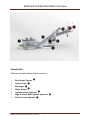
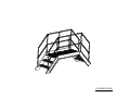
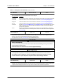
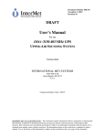
Multicrete Portable Mix Station Overview
❸
❷
❼
❶
❹
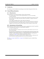
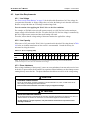
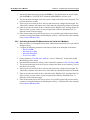
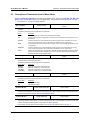
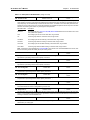
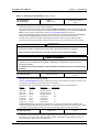
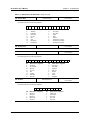
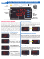
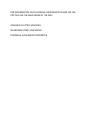
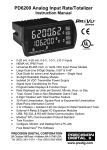
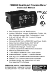
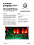
Introduction
Multicrete’s Portable Mixing Station consists of:
Feed Auger System ❶
Incline Auger ❷
Mix Auger ❸
Water System ❹
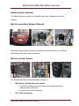
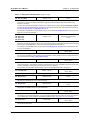
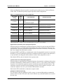
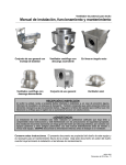
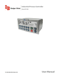
Addmix system (optional) ❺
High Pressure Wash System (optional) ❻
Electric Control System ❼
Multicrete Portable Mix Station Overview
3
❺
❻
Multicrete Portable Mix Station Overview
Feed Auger System
The Feed Auger System is designed to hold one yard (two yards with extensions) of preweighed dry shotcrete materials. The Metering Auger feeds material from the flooded
hopper to the Incline Auger at a controlled rate using the Variable Frequency Drive (VFD).
The Metering Auger is activated by a start/stop switch located on the Control Panel.
The Feed Auger System consists of feed hopper, vibrators and metering auger.
Incline Auger System
The Incline Auger feeds material from the Feed Auger system to the Incline Auger at a
fixed speed. The Incline Auger is activated by a start/stop switch located on the Control
Panel.
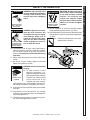
Mixing Auger System
The Mix Auger serves two purposes: to convey material from the Incline Auger to the transport
Multicrete Portable Mix Station Overview
4
Multicrete Portable Mix Station Overview
vehicle, and to add mix water and Addmix chemical into the material to create a full
wet mix of material.
The Mix Auger is activated by a switch on the Control Panel.
Note: Replace shoe before it wears into base metal (approx. 1/8")
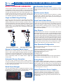
Water System
The Water System is comprised of the following components:
Water Feed Tank: A holding tank to supply water to the system.
Supply Pump: Manual/Auto control. When in auto, booster pump runs to supply
water from the Water Feed Tank when the Batch Controller requests supply.
Manual control has no interlocking and should primarily be used with operation of
the High Pressure Wash System.
Mag Flow Meter: Monitors flow rate, sends out pulse signal to the Water Batch
Controller and displays flow rate.
Electric Actuated Ball Valve and Gate Valve: controls water flow and is
activated by the Water Batch Controller.
Water Batch Controller: Monitors water volume used (Liters). Controls Water Valve
accordingly.
Water Header: Provides water distribution to Mix Auger.
Multicrete Portable Mix Station Overview
5
Multicrete Portable Mix Station Overview
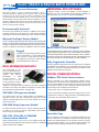
Addmix System (optional)
The Addmix System consists of a peristaltic tube pump, a Mag flow meter with
indicator.
High Pressure Wash System (Optional)
The High Pressure Wash System is a standalone unit that provides up to 2500 psi
for Mix Auger and other required cleanouts.
Electrical Control System
The Portable Mix Station Electrical Design consists of:
Main Fused Lockable Disconnect Switch
o Provides a lockable disconnect means with viewing window for
stab operation verification.
o Fused for short circuit protection.
600 / 120V Transformer
Multicrete Portable Mix Station Overview
6
Multicrete Portable Mix Station Overview
Electrical Control System-cont.
Main Control Panel
o 3 Kilo Volt Ampere (KVA) Transformer for system 120V control power
o Mix Auger, Incline Auger and Metering Auger Start/Stop
o Hopper Vibrators momentary Start button
o Water Valve, Addmix and Booster Pump Hand/Off/Auto
o E-Stop for emergency situations. Not intended to be used as a
safety device for maintenance, cleanup, etc.
Water Batch Control Panel
o Monitors flow rate using pulse inputs
o Display batch total liters (gallons optional)
When all switches are in Auto:
o Controls Water Valve operation
o Controls Addmix operation
o Controls Booster Pump operation
Mix Auger Remote Lockable Disconnect
o Provides a lockable disconnect means for safe isolation of Mix Auger.
Mix Auger Remote Start/Stop Control with system E-Stop
o Remote Start/Stop on catwalk, primarily used for clean out purposes. EStop is an entire system E-Stop for emergency situations and is not
intended to be used as a safety device for maintenance, cleanup, etc.
Addmix Controller
o Displays total Addmix volume or flow.
Metering Auger VFD
o Provides speed control for the Metering Auger.
Multicrete Portable Mix Station Overview
7
Multicrete Portabl e Mixing Station
OPERATION
JANUARY 2014
8
Multicrete Portable Mix Station Operation
Feed Auger System
The Feed Auger System provides storage for dry pre-blended material for consistent
volumetric delivery of material. The Feed auger system needs to be filled with a pre
weighed volume of pre-blended material. The system will use the metering auger along
with the VFD to feed material at a controlled rate for a consistent feed. The operator
must pre load material into hopper before starting, additional material may be added
quickly to keep a consistent mix at the mix auger. The system may be stopped
momentarily if required to add additional material however shut down and start up
procedure must be followed to ensure consistent delivery.
The operator must monitor volume in hopper and operate the vibrators manually at
the end of the batch to ensure ALL material is used in the mix.
Incline Auger System
The Incline Auger is used to convey material from feed auger to the mix auger. The
Incline auger is started from the main control panel. The Incline Auger is interlocked
through the Mix Auger auxiliary contact. The Mix Auger must be running to allow the
Incline Auger to run. The incline auger has a clean out located at the discharge.
Remove to check the discharge for buildup occasionally the frequency of this will need
to be monitored to prevent excessive build up.
Follow Lock out procedure by locking out main control panel prior to removing cover.
Mix Auger System
The Mix Auger is started from the main control panel. The Mix Auger is a fixed speed
volumetric mixer designed to provide a complete mix of materials as they are fed
volumetrically at a controlled rate. The mix auger has a remote start/stop station and
local disconnect located on the catwalk to assist with clean up. The Mix auger is
cleaned by opening the main cover held down with the over center handles on the
main frame.
Follow lock out procedure by using the local disconnect on the catwalk before
opening or removing mix auger covers.
Water System
The water system is comprised of water holding tank, supply pump, Water Mag flow
meter, electric actuated valve and batch controller. There is also a standalone high
pressure wash system (optional) for system cleanup.
Multicrete Portable Mix Station Operation
9
Multicrete Portable Mix Station Operation
The water batch controller dictates the action of the water process while the system in
Auto. The batch controller is designed to deliver a preset volume of water by controlling
the water valve. The batch control is able to learn the overrun value, therefore a
consistent supply of water is supplied by means of the holding tank and supply pump.
The water valve, Addmix and booster pump are interlocked with the Metering Auger
running signal.
The auto batch controller gets its signal from the Water mag flow meter. The water mag
flow meter will provide a signal to the batch controller based on volume. The water
meter will also display the actual flow rate.
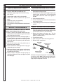
Addmix System (optional)
The Addmix System can be operated in hand or auto. When used in auto the Addmix
will operate while the water valve is open in the auto mode. The flow rate is adjusted
using the variable speed controller located on the side of the pump drive. The pump is
a peristaltic tube pump, the tube is a consumable item, and is easily replaced by
removing the cover and installing a new tube. The volume of the pump is also adjusted
by changing the size of tube. Tube material will be determined from the MSDS
information of the chemical used.
System Set-up
To begin system set up, the system must be calibrated using the following procedure:
1. Fill the feed hopper with desired batch volume
2. Run system with no water and record time required to deliver complete batch
3. Determine approximate total water and add mix required per batch
4. Calculate desired water flow rate based on material delivery time and required water
5. Manually run water and adjust flow using the gate valve while monitoring water
flow meter. Set to desired flow rate based on previous calculations.
6. Calculate desired Addmix flow rate based on total required and material delivery time.
7. Manually operate the add mix pump and adjust the flow rate using the variable
speed controller located on the side of the pump drive.
Once set up is complete, proceed to produce material in auto function. Total volumes
of material and desired slump must be monitored and adjustments made as required.
Multicrete Portable Mix Station Operation
10
Multicrete Portable Mix Station Operation
Operation sequence
1.
Turn on power to mix station.
2.
Grease the bearing seal on the mix auger.
3.
Check that the water tote is full.
4.
Load the hopper with product. The first bag must be emptied into the first hole on the hopper.
Three (3) will fill up the hopper. Depending on batch size, have a fourth bag hanging over the
hopper and opened.
5.
Ensure the transmixer is parked properly underneath the discharge chute of the mix auger.
6.
Ensure that the water amount is properly programmed on the water batch system. (See
separate instructions).
7.
Turn the water pump and booster pump switch to Auto.
8.
Start the augers in the order of: mix auger, incline auger, metering auger.
9.
Wait 75 seconds* and then start the water.
10.
Watch the flow meter and adjust to roughly 58 litres/min.*
11.
Periodically, run the vibrator to move product in the hopper.
12.
Check the transmixer to ensure that the mix is not piling up.
13.
If the mix is piling up, stop the batch process by pressing the Stop button for the metering
auger and incline auger. This will shut off the water after 3 seconds. Let the mix auger run
for about 15 seconds to empty out any excess material.
14.
The transmixer can now move to the next opening. Batching can now resume by starting
the mix auger, incline auger, and metering auger in that order. The water will automatically
turn on; monitor the flow rate to ensure it returns to the original setting.
15.
Once the hopper is empty, turn off the metering auger.
16.
Once the desired batch water has been reached, let the incline auger run for another two
(2) minutes to let any material run through before turning it off.
17.
Let the mix auger run for another minute before turning it off.
18.
The transmixer operator can pull away from under the discharge chute and let the truck
mix for another five (5) minutes.
* Adjustments to these numbers can be made.
Multicrete Portable Mix Station Operation
11
Multicrete Portable Mix Station Operation
System Clean-up
It is critical the Mix Auger is cleaned and maintained in good condition in
order to produce good consistent mix while minimizing maintenance.
It is good practice to use the last part of the batch water to start the pre-cleaning of the
Mix Auger. This is done by adjusting the water and material flow rates to have the dry
material to run out before the water is complete.
Upon completion of the batch, the vehicle can be removed and water can be run
through the Mix Auger to start the wash procedure. After the pre wash is complete, it is
necessary to do a manual wash.
1. Lock out Mix Auger using the local disconnect located on the catwalk.
2. Open Mix Auger cover and fold back
3. Remove mix spray bars and clean thoroughly
4. If the optional High Pressure Wash system is installed, use it to wash
auger completely. Otherwise, use the hand wash hose to wash auger
completely.
5. Close the mix auger cover and unlock local disconnect and run using the controls located
on the catwalk.
6. Check auger again for material left on auger.
7. Reinstall spray bars and close cover
8. Repeat procedure as required.
9. Check incline discharge weekly or as required for build up.
Multicrete Portable Mix Station Operation
12
Multicrete Portable Mix Station Operation
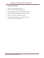
Setting Water Meter
1.
Press F2 to bring up preset water total.
2. Press F1 to go to the desired number change.
3. Once on desired number, press F2 to change set number.
4. Repeat steps 2 and 3 until desired water total is reached.
5.
Press F3 to confirm the total amount of water.
6.
Press F2 to double check the correct total has been set.
7. Press F3 to return to the ready screen.
Multicrete Portable Mix Station Operation
13
Multicrete Portabl e Mixing Station
MAINTENANCE
JANUARY 2014
14
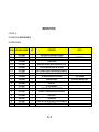
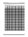
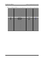
MAINTENANCE
SCHEDULE
Multicrete Portable Mixing Station
Maintenance Checklist
Description
Each
batch
Daily
Frequency
150
500
6000
yard³ yard³ yard³
1. Feed Hopper System
1.1 Hopper Vibrators
1.1.1 Check Hopper for cracks around vibrator mounts
X
1.1.2 Check amplitude to ensure sufficient to move
material and not to cause hopper failure
X
1.2 Feed Auger Screw
1.2.1 Visually inspect auger flighting for wear (critical
wear will occur at discharge area)
X
1.3 Check for wear on trough (annually)
X
1.4 Check oil level and color in reducer monthly
X
1.4.1 Replace annually
1.5 Lube discharge bearing weekly one shot
X
X
2. Incline Auger Screw
2.1 Visually inspect auger flighting for wear. Remove
covers 10,000 Tons increase inspection as required.
X
2.2 Check for wear on trough annually
2.3 Check oil level and color in reducer monthly
X
2.3.1 Replace annually
X
2.4 Lube discharge bearing weekly one shot
3. Mix auger
3.1 Lube infeed bearing
3.2 Clean auger
3.3 Check condition of all replaceable wear flights
weekly replace as required.
X
X
X
X
X
3.4 Check condition of trough lower belt and cover
X
3.5 Check oil level and color in reducer monthly
3.5.1 Replace annually
X
3.6 Grease mix auger lower bearing
15
X
X
As
Req.
Initial
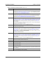
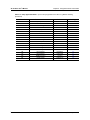
MAINTENANCE
SCHEDULE
Multicrete Portable Mixing Station
Maintenance Checklist
Description
Each
batch
4. Water system
Daily
150
yard³
4.1 Clean infeed strainer weekly or as required
4.2 Check pump for leaks at seal
4.2.1 Replace as required
X
X
4.3 Drain back wash filter or pressure washer supply
weekly or as required
4.4 Check all hoses for wear and cracks
4.4.1 Replace as required
X
X
5. Structure
5.1 Check structure for cracks weekly, repair as req.
5.2 Check all platform supports and anchors, repair
as required
5.3 Check all stairs and platform grating for condition
and obstuctions
5.4 Check condition of all handrails for condition
X
X
X
X
16
Frequency
500
6000
yard³ yard³
As
Initial
require
d
X
X
X
X
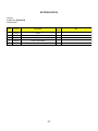
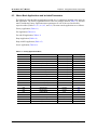
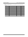
MULTICRETE PORTABLE MIXING STATION
CALIBRATION CHECK SHEET
Date
Volume material
loaded
VFD set
rate
Time
Total water
required
Water liter/min
17
Total Add Add mix 1 Total Add Add Mix 2
Mix 1
ML/min Mix 2
ML/min
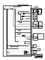
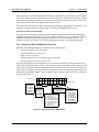
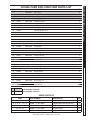
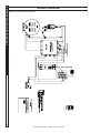
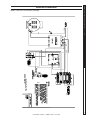
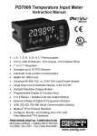
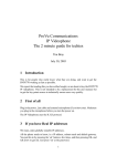
MSI PORTABLE MIXING STATION
Feed From
3KVA 120V
Transformer
TB1 1
30 Amp
CB
Remove
Jumper To
Wire Remote
E-Stop
TB3
TB4
4
5
TB2
3
MAIN CONTROL PANEL
TB5
6
Door
E-Stop
F1
10 Amp
FIELD DEVICES
2-N
TB6
7
Batch Controller
PD6310
TB7
8
34
5 Com
4 Sig +
35
KROHNE
IFC 100
Water Meter
DD
Off
Hand Auto
N
CR1
10
9
M3-CR4
Hand
Water Valve
Relay CR1
Auto
Add Mix
Relay CR2
14
15
Stop
TB10
16
Start
Input 2
Water
Stop
Input 3
Auto
12
TB9
Water
Start
Input 1
CR2
11
Hand
L
5 Volt Sig
M7 O/L
13
Input 4
Booster
Pump
17
M1 O/L
M7
expansion
module
PDA1044
M1
Mix
Auger
Metering Auger
Local Disconnect
Remote Start/Stop
M1 Aux
Remote
Stop
Local
Disconnect Aux.
Remote
Start
Catwalk
E-Stop
18
19
Stop
Start
20
M1 Aux
21
M2
M2 O/L
Incline
Auger
M2 Aux
22
23
Stop
Start
24
M3
M2 Aux
Metering
Auger CR3
M3-CR4
TB11
25
Vacon X4 A.C. Drive
Metering Auger VFD
24V
26
M3-CR3
Page 62 -> Input 201
= L/R Rem Ctl
Page 70 -> Input 509 = 575 Volts
Input 510 =14.5Amps
Input 511 = 1775
FWD
TB12
RC 2
27
Page 72 -> Input 525
= Ramp Mode
N.O. 2
TB13
CR4
Metering
Auger Running
Metering Auger
Running CR4
28
28A
Start
M4 O/L
M4
Hopper Vib 1
28B
M5 O/L
29 TB14
F2
6 Amp
FNQR
M5
Hopper Vib 2
30
TB15
31
TB17
Water Valve
3 Open
2 Close
TB16
Water
Valve CR1
32
F3
6 Amp
FNQR
Water
Valve CR1
PERISTALTIC ADMIX
PUMP (optional)
1N
TB18
33
M6
Add Mix
CR2
Add Mix Pump
60W POWER SUPPLY
120V – 24VDC
34
35
Flow Meter
TB19
SM6000 ADMIX FLOW
METER (OPTIONAL)
36
TB20
F4
2 Amp
FNQR
37
F5
6 Amp
FNQR
TB21
GFI
MSI PORTABLE
MIXING STATION
DEC 17/2013
18
Sheet 1 of 2
DWG # : MS E1001 Rev. 2
Prepared By: AVA
19
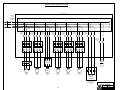
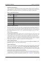
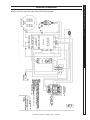
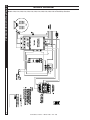
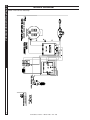
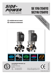
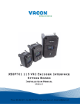
MSI PORTABLE MIXING STATION
Main Control Panel
100 Amp
Fuses
EXTERNAL FUSED
DISCONNECT
600Volt Splitter
30 Amp
Time Delay
LPJ
30 Amp
Time Delay
LPJ
3 Amp
Time Delay
FNQR
30 Amp
Time Delay
LPJ
3 Amp
Time Delay
FNQR
15 Amp
Time Delay
LPJ
20 Amp
Time Delay
LPJ
8 Amp
Time Delay
FNQR
3KVA
600 V
Benshaw
RSI S4 Series
15 HP VFD
120 V
120 V Control
Transformer
M
M
M
M
M
M
M1
Mix Auger
15 HP
M2
Incline Auger
15 HP
M3
Metering Auger
15 HP
M4
Hopper Vib 1
0.75 HP
M5
Hopper Vib 2
0.75 HP
M7
Booster Pump
3-5 HP
M
M8
Stand Alone High
Pressure Pump System
10 HP
MSI PORTABLE
MIXING STATION
Dec17/2013
20
Sheet 1 of 2
DWG # : MS E1001 Rev. 2
Prepared By: AVA
MSI PORTABLE MIX STATION
PARTS CATALOGUE
MSI PORTABLE MIX STATION
PARTS CATALOGUE
D
C
A
E
B
F
G
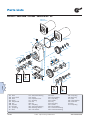
Parts Ordering Contact Multicrete
Winnipeg:
(P) 204-262-5900
(F) 204-262-5909
PORTABLE MIX STATION
SECTION
DESCRIPTION
PG
A
B
C
D
E
F
G
HOPPER
A1
B1
C1
D1
E1
F1
G1
MEETERING AUGER
INCLINE AUGER
MIX AUGER
SUSPENDED PLATFORM
INCLINE SKID
WATER / ACCELERATOR
SPARE PARTS
1
2
3
4
5
(A) INFEED HOPPER/SKID
MSI PORTABLE MIX STATION
ITEM CODE: A
EQUIPMENT NAME: INFEED HOPPER (A)
EQUIPMENT NUMBER: Item N°
Part number
Part Description
1
2
3
4
5
5015-00053
5015-00054
5015-00055
1400-62102
5015-00056
Hopper lid
Hopper extension
Hopper
2P-200-3-575 VIBCO VIBRATOR
Skid
Quantity
required
1
1
1
2
1
A-2
Notes
5
8
7
9
10
6
1
2
3
4
11
12
13
11
14
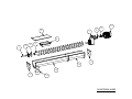
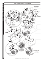
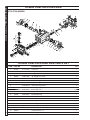
(B) METERING AUGER
MSI PORTABLE MIX STATION
ITEM CODE: B
EQUIPMENT NAME: METERING AUGER (B)
EQUIPMENT NUMBER: Item N°
Part number
Part Description
1
2
3
3-A
4
5
6
7
8
9
10
11
12
13
14
5015-30044
5012-10003
5012-10002
5012-10034
5015-30065
5015-10003
5015-10047
5012-00020
5012-00034
5012-00026
5010-00001
5015-10048
5015-10049
5015-10050
1309-04810
STUB SHAFT 13" LONG 2 7/16 DIA HOLES AT 1.5 &4.5" MS S1007
Flange Block Bearing 2 7/16
2 7/16" Waste Pack Seal
Waste paking material
Metering auger assy with bushings
Trough cover
Trough shroud
NORD SK5282SCP/VL 250TC 43 RPM 20 HP 2 7/16"
NORD COUPLING SLEEVE FOR 250TC
NORD SK 5282SCP/VL and 4282 COUPLING HALF 52683390
15 HP-35-18T-254TC 575V Elec Motor
End plate
Trough with flanges
Trough with flanges with discharge spout
Discharge sock 10"ID
B-2
Quantity
required
1
1
1
1
1
1
1
1
1
1
1
2
1
1
per foot
Notes
Item not shown - ordered by the pound
5
4
3
14
2
10
1
12
10
13
11
10
8
6
10
9
19
7
18
17
16
15
(C) INCLINE AUGER
MSI PORTABLE MIX STATION
ITEM CODE: C
EQUIPMENT NAME: INCLINE AUGER (C)
EQUIPMENT NUMBER: Item N°
Part number
Part Description
1
2
3
4
5
6
7
8
8 -A
9
10
11
12
13
14
15
16
17
18
19
5015-10053
5015-10054
5015-10055
1365-40145
5015-10056
5015-30044
5012-10003
5012-10002
5012-10034
5015-30066
5015-10014
5012-00049
5012-00034
5012-00026
5010-00001
5015-10006
5015-10051
5015-10052
1309-04810
5015-10048
Inlet Assembly
12" Trough cover
12" Trough cover
5/8" DWYIDAG NUT WITH MSI MACHINED BOTTOM
Trough cover
STUB SHAFT 13" LONG 2 7/16 DIA HOLES AT 1.5 &4.5" MS S1007
Flange Block Bearing 2 7/16
2 7/16" Waste Pack Seal
Waste paking material
Incline auger assy with bushings
Trough shroud
NORD SK5282SCP/VL-210TC 2 7/16" SHAFT 25:1 70 RPM
NORD COUPLING SLEEVE FOR 250TC
NORD SK 5282SCP/VL and 4282 COUPLING HALF 52683390
15 HP-35-18T-254TC 575V Elec Motor
End Plate
Trough with flanges - 10' Long
Trough with flanges and discharge - 9¼' Long
Discharge sock
End plate
C-2
Quantity
required
1
1
1
1
1
1
1
1
1
1
4
1
1
1
1
1
1
1
Per foot
1
Notes
12" Trough cover custom 108 ¾" Long - Mix Station
12" Trough cover custom 86 ¾" Long - Mix Station
Item not shown - ordered by the pound
Brackets supplied loose
3
5
4
6
7
2
1
8
9
(D) MIX AUGER
MSI PORTABLE MIX STATION
ITEM CODE: D
EQUIPMENT NAME: MIX AUGER (D)
EQUIPMENT NUMBER: Item N°
Part number
Part Description
1
2
3
4
5
6
7
8
9
5015-10056
5015-00052
5015-10057
5012-00024
5012-00026
5012-00034
5010-00001
5015-10058
1309-04810
Mix auger inlet cover with spray bars
Mix auger assembly with mounts
Gearbox mount plate
NORD SK 4282SCP/VL 250TC 2" SHAFT 289 RPM
NORD SK 5282SCP/VL and 4282 COUPLING HALF 52683390
NORD COUPLING SLEEVE FOR 250TC
15 HP-35-18T-254TC 575V Elec Motor
Mix auger discharge assy
Sleeve sock- 10" ID
D-2
Quantity
required
1
1
1
1
1
1
1
1
Per foot
Notes
See catalogue
0,;$8*(5$66(0%/<;
,WP
3DUW1R
4W\
'HVFULSWLRQ
,WP
3DUW1R
'HVFULSWLRQ
4W\
7XEH&ODPS
5(
+RVH&DUULHU
$*&
$XJHU:HOGPHQW[
5(
&ODPS3ODWH
5(
6WLU7DE
5(
&ODPS3ODWH
$*55
$XJHU0DWW[
5(,
5HWDLQLQJ6WUDS
$*55&
&RYHU0DW[
5(,
/DWFK
$*55*
7RS&RYHU([WHQVLRQ
5(,
&ODPS$QJOH:HOGPHQW
$*55
$XJHU7URXJK([WHQVLRQ
5(,
3LQ$XJHU/LIW
$*55
%HDULQJ6SODVK*XDUG
5(-
)UDPH:HOGPHQW[
$*55
/DWFK6HDO
5(-
%UDFNHW6HQVRU7DUJHW
:HDU3ODWH$XJHU
5(-
+\GUDXOLF/LQH
51
5(-
)UDPH:HOGPHQW[
(/
$XJHU&RYHU6ZLWFK
5(-
+LQJH3ODWH:HOGPHQW
5(
&ODPS3ODWH
5(-
+LQJH3ODWH:HOGPHQW
5(
&ODPS3ODWH
5(-
&ODPS3ODWH
)HE
:HDU3ODWH6WLU7DE
%
AUGER SEAL ASSEMBLY, 2" BEARING
3
20
19
15
16
5
14
4
8
18
1
10
7
2
11
13
6
9
17
12
Itm
Part No.
Description
Qty
Itm
Part No.
Description
Qty
1
126115
2
Capscrew, 1/2 x 1 1/2 NC
11
389108
2
Washer, 1/2 Lock
2
126121
4
Capscrew, 1/2 x 3 NC
12
AGBR003
1
Bearing, Link-belt
5012-10021
3
126171
2
Capscrew, 5/8 x 3 1/2 NC
4
189001
1
Grease Nipple, 1/8-NPT
13
1400-51007
1
Straight
14
AGSL003D
1
Grease Hose, 12"
Coupling, 02 FNPT-02
15
1400-51004
1
AR Weld-on Plate
FNPT
16
1400-51005
1
AR Bolt-on Plate
5
196198
1
EFRB22432H
Seal
6
226008
2
Nut, 1/2 Hex NC
17
AGSL003B
1
Lower Seal Pressure Plate
7
233108
4
Nut, 1/2 Stover NC
18
AGSL003C
1
Lower Seal Roll Assembly
8
233111
2
Nut, 5/8 Stover NC
19
1400-51006
1
2
Set Screw 3/8 NC x 3/4
20
AGS001
1
9
338077
10
387308
Sep 2011
2" Auger Idler Shaft
Sleeve, Mix Auger Repair
AS REQ'D Washer, 1/2" SAE
B0200201
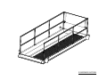
E SUSPENDED PLATFORM
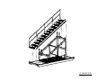
(F) INCLINE SKID
(G) HOPPER STAIRS
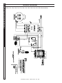
Pressure
washer
5
Pressure gauge
2" ¼ npt
Pressure gauge
2" ¼ npt
M
1250
Liter
tote
2" Check
Valve
1
4
" hose to
tote
Globe valve flow
control 1"gate
1" Ball Valve
1" Wash
hose
Bypass valve 1"
Spray bar 1" HSS
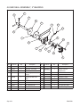
WATER SYSTEM
ITEM CODE: G
EQUIPMENT NAME: WATER SYSTEM (G)
EQUIPMENT NUMBER: ITEM No.
CATALOGUE NUMBER
QTY
DESCRIPTION
NOTES
1
1A
2
3-A
3-B
3-C
4
4-A
5
6
7
8
9
10
11
12
13
5013-00006
5013-00008
5013-10081
5013-10056
5010-00007
5013-10083
5013-00007
5013-00008
1309-00016
5013-10060
5013-10017
5013-10034
5011-00061
5013-10082
1400-41215
5013-10057
5013-10082
1
1
1
1
1
1
1
1
1
1
1
1
1
1
1
1
1
HART BASCKET STRAINER BT1250150032
200 MESH 74 MICRON FILTER ELEMENT
2" CHECK VALVE
NOT SHOWN
90220030 FAC-300-K ENTRIFUGAL PUMP END 2"X2" 3HP
3 HP 575V MOTOR USED WITH FAC-300-K
3 HP 575V AND FAC-300-K PUMP ASSEMBLY COMPLETE
3/4" QUICK CLEAN FILTER HOUSING NO ELEMENT INCLUDED
200 MESH 74 MICRON FILTER ELEMENT
PRESSURE WASHER
HOSE REEL
50' HOSE ASSEMBLY
PRESSURE WASHER WAND ASSEMBLY
KROHNE 1" ENVIROMAG 2000 FLOW SENSOR
1" BALL VALVE
1" GLOBE VALVE
1" BALL VALVE WITH 120V ELEC ACTUATOR COMPLETE
1" BALL VALVE
G-2
NOT SHOWN
SEE HOTSEY MANUAL / 600V
SPARE PARTS
CATALOGUE NUMBER
QTY
DESCRIPTION
LEAD TIME
1
1
1
1
1
1
1
PER FOOT
STUB SHAFT 13" LONG 2 7/16 DIA HOLES AT 1.5 &4.5" MS S1007
PORTABLE MIX STATION MEETERING AUGER WITH BUSHINGS
FLANGE BLOCK BEARING 2 7/16
2 7/16" WASTE PACK SEAL
WASTE PACKING MATERIAL - BY THE POUND
NORD SK 5282SCP/VL and 4282 COUPLING HALF 52683390
15 HP-35-18T-254TC 575V Elec Motor
10" DISCHARGE SOCK
2 - 3 WEEKS
3 - 4 WEEKS
2 - 3 WEEKS
2 - 3 WEEKS
2 - 3 WEEKS
2 - 3 WEEKS
2 - 3 WEEKS
2 - 3 WEEKS
1
1
1
1
1
1
1
1
PER FOOT
STUB SHAFT 13" LONG 2 7/16 DIA HOLES AT 1.5 &4.5" MS S1007
PORTABLE MIX STATION INCLINE AUGER WITH BUSHINGS
FLANGE BLOCK BEARING 2 7/16
2 7/16" WASTE PACK SEAL
WASTE PACKING MATERIAL - BY THE POUND
NORD COUPLING SLEEVE FOR 250TC
15 HP-35-18T-254TC 575V Elec Motor
NORD SK 5282SCP/VL and 4282 COUPLING HALF 52683390
10" DISCHARGE SOCK
2 - 3 WEEKS
3 - 4 WEEKS
2 - 3 WEEKS
2 - 3 WEEKS
2 - 3 WEEKS
2 - 3 WEEKS
2 - 3 WEEKS
2 - 3 WEEKS
2 - 3 WEEKS
1
PER FOOT
1
1
51
6
2
AS REQ
1
1
1
1
PER FOOT
PER FOOT
1
AUGER 9" X 116" WITH WEAR PLATES ALSO INCL AGS001 & AGWP005
DISCHARGE SOCK - MAX 4' LENGTH
NORD SK 5282SCP/VL and 4282 COUPLING HALF 52683390
NORD COUPLING SLEEVE FOR 250TC
WEAR PLATE
WEAR PLATE FOR STIR TAB
SET SCREW
WASHER
BEARING
SEAL ASSEMBLY INCL. AGSL003A,B,C
AR BOLT ON PLATE
15 HP-35-18T-254TC 575V Elec Motor
10" DISCHARGE SOCK
12" DISCHARGE SOCK
2" AUGER IDLER SHAFT
3 - 4 WEEKS
2 - 3 WEEKS
2 - 3 WEEKS
2 - 3 WEEKS
2 - 3 WEEKS
2 - 3 WEEKS
2 - 3 WEEKS
2 - 3 WEEKS
2 - 3 WEEKS
2 - 3 WEEKS
2 - 3 WEEKS
2 - 3 WEEKS
2 - 3 WEEKS
2 - 3 WEEKS
2 - 3 WEEKS
1
1
1
1
1
1
1
1
BASKET STRAINER - ELEMENT
PUMP WET END
3 HP 575V MOTOR USED WITH FAC-300-K
HIGHT TEMP QUICK CLEAN FILTER
200 MESH 74 MICRON FILTER ELEMENT
PRESSURE WASHER WAND ASSEMBLY
FLOW METER
PUMP ELEMENT (FOR OPTIONAL ADD MIX PUMP)
2 - 3 WEEKS
2 - 3 WEEKS
2 - 3 WEEKS
2 - 3 WEEKS
2 - 3 WEEKS
2 - 3 WEEKS
2 - 3 WEEKS
2 - 3 WEEKS
MEETERING AUGER
5015-30044
5015-30065
5012-10003
5012-10002
5012-10034
5012-00026
5010-00001
1309-04810
INCLINE AUGER
5015-30044
5015-30066
5012-10003
5012-10002
5012-10034
5012-00034
5010-00001
5012-00026
1309-04810
MIX AUGER
1400-51021
1309-04810
5012-00026
5012-00034
1400-51001
1400-51003
338077
387308
5012-10021
1400-51007
1400-51005
5010-00001
1309-04810
1309-04812
1400-51006
WATER SYSTEM
5013-00008
5013-10040
5010-00007
5013-00007
5013-00008
5013-10034
5011-00061
5013-10011
X4 AC Drive
user's manual
Need Help?
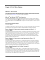
This manual answers most installation and startup questions
that may arise. However, if you have any problems,
please let your first call be to us.
Vacon, Inc.
Chambersburg, PA 17202
Normal business hours:
(North America)
8:00 AM to 5:00 PM, Eastern time
+1 877-Vacon06
(+1 877-822-6606)
After-hours support is also available
and Vacon, Inc. are trademarks of Vacon Plc, a member of Vacon Group.
All other product names are trademarks of their respective companies.
Copyright 2009, Vacon, Incorporated. All rights reserved.
Bold type
Summary of X4 Parameters
No.
Parameter Name
= cannot change in Run
= Level 1 parameter
Options
Default
Model Dependent
Read-only
60
Software Rev
0.00-99.99
Read-only
60
003
Rated Current
0.0-200.0 A
Read-only
60
005
Serial No. 1
0-65535
Read-only
60
001
Model Number
002
User Setting
See Page
006
Serial No. 2
0-65535
Read-only
60
010
Last Fault
text string
Read-only
60
025
4th Fault
text string
Read-only
60
040
3rd Fault
text string
Read-only
60
055
2nd Fault
text string
Read-only
60
070
1st Fault
text string
Read-only
60
102
Output Freq
103
Output Voltage
104
Output Current
105
Drive Load
106
Load Torque
107
Drive Temp
108
Total Run Time
0.0-400.0 Hz
Read-only
61
0-600 V
Read-only
61
0.0-200.0 A
Read-only
61
-200.0-200.0%
Read-only
61
-200.0-200.0%
Read-only
61
-20.0-200.0 °C
Read-only
61
0.0-6553.5 h
Read-only
61
109
Power On Hours
0-65535 h
Read-only
61
110
Stator Freq
0.0-400.0 Hz
Read-only
61
111
DC Bus Voltage
0 - 1000 Vdc
Read-only
61
115
Drive Power Out
0.0-200.0%
Read-only
61
201
Input Mode
text string
Local Only
62
202
Rev Enable
text string
Forward
62
203
Stop Key Remote
text string
Coast
62
204
Ref Select
text string
Vin1
63
205
Vin1 Config
text string
0-10V
63
206
Vin1 Offset
0.0% to 100.0 %
0.00%
63
207
Vin1 Span
10.0% to 200.0%
100.00%
64
208
Cin Config
text string
0-20mA 50
64
209
Cin Offset
0.0% to 100.0%
0.0%
64
210
Cin Span
10.0% to 200.0%
100.0%
64
211
Vin2 Config
text string
0-10V
64
212
Vin2 Offset
0.0% to 100.0 %
0.00%
64
213
Vin2 Span
10.0% to 200.0%
100.00%
64
64
214
Vin1 Filter Time
0 to 1000 ms
20 ms
215
Cin Filter Time
0 to 1000 ms
20 ms
64
216
Vin2 Filter Time
0 to 1000 ms
20 ms
65
217
Trim Ref Enable
218
Trim % Factor
222
301
text string
Disabled
65
-100.0 - 100.0%
0.0%
65
Ref Loss Config
text string
No Fault
65
Min Frequency
0.0 - Max Freq.
0.0 Hz
65
302
Max Frequency
0.0 - 400.0 Hz
60.0 Hz
65
303
Preset Freq 1
Min Freq-Max Freq
5.0 Hz
65
304
Preset Freq 2
Min Freq-Max Freq
10.0 Hz
65
305
Preset Freq 3
Min Freq-Max Freq
20.0 Hz
65
306
Preset Freq 4
Min Freq-Max Freq
30.0 Hz
65
307
Preset Freq 5
Min Freq-Max Freq
40.0 Hz
65
308
Preset Freq 6
Min Freq-Max Freq
50.0 Hz
65
(cont’d)
Note that all parameters can be addressed by adding 40000 to the parameter number. For example, parameter 201 (Input Mode) can be
addressed by Modbus address 40201.
DPD00088A
- iii -
© 2009 Vacon Incorporated All Rights Reserved
X4 AC Drive User’s Manual
Summary of X4 Parameters
Bold type
No.
Parameter Name
= cannot change in Run
= Level 1 parameter
Options
Default
309
Cut-Off Freq
0.0-5.0 Hz
0.0 Hz
User Setting
See Page
401
Ramp Select
text string
ART-DI
66
402
Accel Time 1
0.1-3200.0 sec
5.0 sec
66
403
Decel Time 1
0.1-3200.0 sec
5.0 sec
66
404
Accel Time 2
0.1-3200.0 sec
3.0 sec
67
405
Decel Time 2
0.1-3200.0 sec
3.0 sec
67
406
DC Inject Config
text string
DC at Stop
67
407
DC Inject Time
0.0-5.0 sec
0.2 sec
67
408
DC Inject Level
0.0% to 100.0%
50.0%
67
409
DC Inj Freq
0.0 to 20.0 Hz
0.0 Hz
68
410
DB Config
text string
Internal
68
414
S Ramp Rounding
1 - 100%
25%
68
490
App Macro
text string
Factory
50
491
Seq Appl
text string
Disabled
50
492
SIO Visible
text string
No
50
501
V/Hz Select
text string
Linear Fixed
69
502
Voltage Boost
0.0-50%
1.0%
69
503
V/Hz Knee Freq
25.0-400.0 Hz
60.0 Hz
69
504
Skip Freq Band
0.2-20.0 Hz
0.2 Hz
70
505
Skip Freq 1
Min Freq-Max Freq
0.0 Hz
70
506
Skip Freq 2
Min Freq-Max Freq
0.0 Hz
70
507
Skip Freq 3
Min Freq-Max Freq
0.0 Hz
70
508
Skip Freq 4
Min Freq-Max Freq
0.0 Hz
70
509
Rated Mtr Volt
100V-690V
Model Dependent
70
510
Rated Mtr FLA
50% - 200% of ND Rating
ND Rating
70
511
Rated Mtr RPM
0-24000 rpm
1750 rpm
70
512
Midpoint Freq
0.0 Hz-V/Hz Knee Freq
60.0 Hz
70
513
Midpoint Volt
0.0-100.0%
100.0%
70
514
Motor RS
0.0-655.35 Ohms
Model Dependent
70
515
Power Factor
0.50-1.00
0.80
70
516
Slip Comp Enable
text string
No
71
517
Single Phase
text string
No
71
519
Find Mtr Data
Not active / Motor RS
Not active
71
520
Filter FStator
1 - 100 ms
8 ms
71
521
Start Field En
Yes / No
No
71
522
Filter Time Slip
10 - 1000 ms
100 ms
71
523
Id Percent
0 - 200%
Read-only
72
524
Iq Percent
0 - 200%
Read-only
72
525
Power Fail Config
text string
CTS No Msg
72
526
UV Ride-Thru En
text string
w/ LVT
72
600
Current Lim Sel
text string
Fixed Lvls
73
601
Cur Lim Mtr Fwd
5%-150%
120%
73
602
Cur Lim Mtr Rev
5%-150%
120%
73
603
Cur Lim Reg Fwd
5%-150%
80%
73
604
Cur Lim Reg Rev
5%-150%
80%
73
605
Cur Lim Freq
0-400 Hz
3.0 Hz
73
606
Ramp Time CL
0.1-3200.0 sec
1.0 sec
73
607
Cur Limit Minimum
0 - 50%
10%
73
66
608
Restart Number
text string
0
74
609
Restart Delay
0-60 sec
60 sec
74
(cont’d)
Note that all parameters can be addressed by adding 40000 to the parameter number. For example, parameter 201 (Input Mode) can be
addressed by Modbus address 40201.
DPD00088A
- iv -
© 2009 Vacon Incorporated All Rights Reserved
X4 AC Drive User’s Manual
Summary of X4 Parameters
Bold type
No.
Parameter Name
= cannot change in Run
= Level 1 parameter
Options
Default
text string
Std Ind 60s
74
100 - 1000%
300%
74
Stability Gain
0 - 10
Model Dependent
75
Stability Rate
0 - 1000
Model Dependent
75
700
Vmet Config
text string
Freq Out
75
701
Vmet Span
0.0-200.0%
100.0%
75
702
Imet Config
text string
Drive Load
75
703
Imet Span
0.0-200.0%
100.0%
75
704
Imet Offset
0.0-90.0-%
0.0%
75
705
Relay 1 Select
text string
Drv Fault
76
706
Relay 2 Select
text string
Drive Run
76
707
DO1 Select
text string
Drv Ready
76
610
Timed OL Select
613
Max Regen Ramp
614
615
User Setting
See Page
708
DO2 Select
text string
At Speed
76
720
Active Logic
text string
Active High
76
721
D1 Configure
text string
Preset 1
77
722
D2 Configure
text string
Preset 2
77
723
D3 Configure
text string
Preset 3
77
724
D4 Configure
text string
Alt Ramp
77
725
D5 Configure
text string
Fault Reset
77
726
MOL Polarity
text string
NO Operate
77
727
MOL Configure
text string
MOL
77
801
Program Number
0-9999
0
77
78
802
Start Options
803
PWM Frequency
text string
LS Lockout
0.6-16.0 kHz
3.0 kHz
804
78
Display Mode
text string
Std Disply
78
805
Display Units
alphanumeric
RPM:1
79
809
Display Scale
1-65535
1
79
810
Language
text string
English
79
811
Access Code
0-9999
0
79
812
Freq Ref Output
text string
6FS
79
0.0-200.0%
100.0%
79
text string
Drive load
80
Sweep FWD / REV / F/R
Sweep FWD
80
80
813
Speed Ratio
814
Display Status
816
Fly Catch Mode
850
PI Configure
text string
No PI
851
PI Feedback
text string
Vin1
80
852
PI Prop Gain
0-2000
0
80
853
PI Int Gain
0-10000
0
81
854
PI Feed Gain
0-2000
1000
81
855
PI Error 1
0.00-100.00%
Read-only
81
856
PI Error 2
0.00-100.00%
Read-only
81
857
PI High Corr
0.00-100.00%
100.00%
81
858
PI Low Corr
0.00-100.00%
0.00%
81
900
SIO Protocol
text string
RTU N81
81
901
SIO Baud Rate
text string
9600
81
902
Comm Drop #
1-247
1
81
81
903
SIO Timer
0.0-60.0 sec
1.0 sec
904
SIO Cntl Word
text string
0x0000
82
905
Ext Ref Freq1
Min-Max Freq
0.0 Hz
82
906
Ext Ref Freq2
Min-Max Freq
0.0 Hz
82
(cont’d)
Note that all parameters can be addressed by adding 40000 to the parameter number. For example, parameter 201 (Input Mode) can be
addressed by Modbus address 40201.
DPD00088A
-v-
© 2009 Vacon Incorporated All Rights Reserved
X4 AC Drive User’s Manual
Summary of X4 Parameters
Bold type
No.
Parameter Name
= cannot change in Run
= Level 1 parameter
Options
Default
908
Status Word
text string
Read-only
User Setting
See Page
909
DI Status
text string
Read-only
82
910
Vin1 Status
0.00-100.00%
Read-only
83
911
Cin Status
0.00-100.00%
Read-only
83
912
Vin2 Status
0.00-100.00%
Read-only
83
913
Output Status
text string
Read-only
83
82
914
Vmet Status
0.00-100.00%
Read-only
83
915
Imet Status
0.00-100.00%
Read-only
83
916
Infrared Baud
n/a
9600
83
931
Seq Cntl 1
n/a
00000000000
83
932
Seq Cntl 2
n/a
00000000000
83
933
Seq Cntl 3
n/a
00000000000
83
934
Seq Cntl 4
n/a
00000000000
83
935
Seq Cntl 5
n/a
00000000000
83
936
Seq Cntl 6
n/a
00000000000
83
937
Seq Cntl 7
n/a
00000000000
83
938
Seq Cntl 8
n/a
00000000000
83
939
Seq Cntl 9
n/a
00000000000
83
951
Seq Count 1
0-65535
0
84
952
Seq Count 2
0-65535
0
84
953
Seq Count 3
0-65535
0
84
954
Seq Count 4
0-65535
0
84
955
Seq Count 5
0-65535
0
84
956
Seq Count 6
0-65535
0
84
957
Seq Count 7
0-65535
0
84
958
Seq Count 8
0-65535
0
84
959
Seq Count 9
0-65535
0
84
Note that all parameters can be addressed by adding 40000 to the parameter number. For example, parameter 201 (Input Mode) can be
addressed by Modbus address 40201.
DPD00088A
- vi -
© 2009 Vacon Incorporated All Rights Reserved
X4 AC Drive User’s Manual
Table of Contents
CONTENTS
Summary of X4 Parameters . . . . . . . . . . . . . . . . . . . . . . . . . . . . . . . . . . . . . . . . . . . . . . . . . . iii
Chapter 1: Introduction . . . . . . . . . . . . . . . . . . . . . . . . . . . . . . . . . . . . . . . . . . . . . . . . . . . . . . 9
1.1 Product Overview . . . . . . . . . . . . . . . . . . . . . . . . . . . . . . . . . . . . . . . . . . . . . . . . . . . 9
1.2 Overview of This Manual . . . . . . . . . . . . . . . . . . . . . . . . . . . . . . . . . . . . . . . . . . . . . 9
1.3 User’s Manual Publication History . . . . . . . . . . . . . . . . . . . . . . . . . . . . . . . . . . . . . 10
Chapter 2: Technical Characteristics . . . . . . . . . . . . . . . . . . . . . . . . . . . . . . . . . . . . . . . . . .
2.1 Interpreting Model Numbers . . . . . . . . . . . . . . . . . . . . . . . . . . . . . . . . . . . . . . . . . .
2.2 Power and Current Ratings . . . . . . . . . . . . . . . . . . . . . . . . . . . . . . . . . . . . . . . . . . .
2.3 Environmental Specifications . . . . . . . . . . . . . . . . . . . . . . . . . . . . . . . . . . . . . . . . .
2.4 Electrical Specifications . . . . . . . . . . . . . . . . . . . . . . . . . . . . . . . . . . . . . . . . . . . . .
2.5 Control Features Specifications . . . . . . . . . . . . . . . . . . . . . . . . . . . . . . . . . . . . . . .
2.6 Dimensions and Weights . . . . . . . . . . . . . . . . . . . . . . . . . . . . . . . . . . . . . . . . . . . . .
11
11
12
13
14
15
16
Chapter 3: Receiving and Installation . . . . . . . . . . . . . . . . . . . . . . . . . . . . . . . . . . . . . . . . .
3.1 Preliminary Inspection . . . . . . . . . . . . . . . . . . . . . . . . . . . . . . . . . . . . . . . . . . . . . . .
3.2 Installation Precautions . . . . . . . . . . . . . . . . . . . . . . . . . . . . . . . . . . . . . . . . . . . . . .
3.3 Dissipation Requirements . . . . . . . . . . . . . . . . . . . . . . . . . . . . . . . . . . . . . . . . . . . .
3.4 Cover Assembly and Torque Specifications . . . . . . . . . . . . . . . . . . . . . . . . . . . . . .
3.5 Serial Number Label . . . . . . . . . . . . . . . . . . . . . . . . . . . . . . . . . . . . . . . . . . . . . . . .
3.6 Conduit Usage . . . . . . . . . . . . . . . . . . . . . . . . . . . . . . . . . . . . . . . . . . . . . . . . . . . . .
3.7 Condensation . . . . . . . . . . . . . . . . . . . . . . . . . . . . . . . . . . . . . . . . . . . . . . . . . . . . . .
20
20
20
21
22
23
23
23
Chapter 4: Connections . . . . . . . . . . . . . . . . . . . . . . . . . . . . . . . . . . . . . . . . . . . . . . . . . . . . . 24
4.1 Introduction . . . . . . . . . . . . . . . . . . . . . . . . . . . . . . . . . . . . . . . . . . . . . . . . . . . . . . . 25
4.2 General Wiring Information . . . . . . . . . . . . . . . . . . . . . . . . . . . . . . . . . . . . . . . . . . 25
4.2.1 Wiring Practices . . . . . . . . . . . . . . . . . . . . . . . . . . . . . . . . . . . . . . . . . . . . . . . . . .25
4.2.2 Considerations for Power Wiring . . . . . . . . . . . . . . . . . . . . . . . . . . . . . . . . . . . .25
4.2.3 Considerations for Control Wiring . . . . . . . . . . . . . . . . . . . . . . . . . . . . . . . . . . .26
4.3 Input Line Requirements . . . . . . . . . . . . . . . . . . . . . . . . . . . . . . . . . . . . . . . . . . . . . 27
4.3.1
4.3.2
4.3.3
4.3.4
4.3.5
4.3.6
4.3.7
Line Voltage . . . . . . . . . . . . . . . . . . . . . . . . . . . . . . . . . . . . . . . . . . . . . . . . . . . .27
Line Capacity . . . . . . . . . . . . . . . . . . . . . . . . . . . . . . . . . . . . . . . . . . . . . . . . . . . .27
Phase Imbalance . . . . . . . . . . . . . . . . . . . . . . . . . . . . . . . . . . . . . . . . . . . . . . . . .27
Single-phase Operation . . . . . . . . . . . . . . . . . . . . . . . . . . . . . . . . . . . . . . . . . . . .28
Ground Fault Circuit Interrupters . . . . . . . . . . . . . . . . . . . . . . . . . . . . . . . . . . . .28
Motor Lead Length . . . . . . . . . . . . . . . . . . . . . . . . . . . . . . . . . . . . . . . . . . . . . . .28
Using Output Contactors . . . . . . . . . . . . . . . . . . . . . . . . . . . . . . . . . . . . . . . . . . .28
4.4 Terminals Found on the X4 Power Board . . . . . . . . . . . . . . . . . . . . . . . . . . . . . . . . 29
4.4.1 Description of the Terminals . . . . . . . . . . . . . . . . . . . . . . . . . . . . . . . . . . . . . . . .29
4.4.2 Typical Power Connections . . . . . . . . . . . . . . . . . . . . . . . . . . . . . . . . . . . . . . . . .30
4.5 Dynamic Braking . . . . . . . . . . . . . . . . . . . . . . . . . . . . . . . . . . . . . . . . . . . . . . . . . . . 32
4.6 Terminals Found on the X4 Control Board . . . . . . . . . . . . . . . . . . . . . . . . . . . . . . . 34
4.6.1 Description of the Control Terminals . . . . . . . . . . . . . . . . . . . . . . . . . . . . . . . . .34
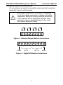
4.6.2 Typical Connection Diagrams for Digital Inputs . . . . . . . . . . . . . . . . . . . . . . . .37
DPD00088A
- vii -
© 2009 Vacon Incorporated All Rights Reserved
X4 AC Drive User’s Manual
Table of Contents
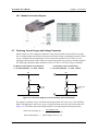
4.6.3 Typical Connection Diagrams for Analog Inputs . . . . . . . . . . . . . . . . . . . . . . . .38
4.6.4 Typical Connection Diagrams for Analog Outputs . . . . . . . . . . . . . . . . . . . . . . .38
4.6.5 Modbus Connection Diagram . . . . . . . . . . . . . . . . . . . . . . . . . . . . . . . . . . . . . . .39
4.7 Reducing Current Surges and Voltage Transients . . . . . . . . . . . . . . . . . . . . . . . . . . 39
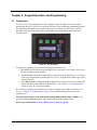
Chapter 5: Keypad Operation and Programming . . . . . . . . . . . . . . . . . . . . . . . . . . . . . . .
5.1 Introduction . . . . . . . . . . . . . . . . . . . . . . . . . . . . . . . . . . . . . . . . . . . . . . . . . . . . . . .
5.2 Keypad Operation . . . . . . . . . . . . . . . . . . . . . . . . . . . . . . . . . . . . . . . . . . . . . . . . . .
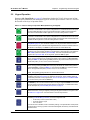
5.3 LCD Displays . . . . . . . . . . . . . . . . . . . . . . . . . . . . . . . . . . . . . . . . . . . . . . . . . . . . .
5.3.1
5.3.2
5.3.3
5.3.4
40
40
41
43
Control . . . . . . . . . . . . . . . . . . . . . . . . . . . . . . . . . . . . . . . . . . . . . . . . . . . . . . . . .43
X4 Keypad Status and Warning Messages . . . . . . . . . . . . . . . . . . . . . . . . . . . . .43
Rights . . . . . . . . . . . . . . . . . . . . . . . . . . . . . . . . . . . . . . . . . . . . . . . . . . . . . . . . . .45
Other Data . . . . . . . . . . . . . . . . . . . . . . . . . . . . . . . . . . . . . . . . . . . . . . . . . . . . . .45
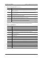
5.4 Keypad Display Window . . . . . . . . . . . . . . . . . . . . . . . . . . . . . . . . . . . . . . . . . . . . . 45
5.5 Programming . . . . . . . . . . . . . . . . . . . . . . . . . . . . . . . . . . . . . . . . . . . . . . . . . . . . . . 46
5.5.1
5.5.2
5.5.3
5.5.4
5.5.5
5.5.6
Accessing Parameters . . . . . . . . . . . . . . . . . . . . . . . . . . . . . . . . . . . . . . . . . . . . .46
Changing the Display Scroll Rate . . . . . . . . . . . . . . . . . . . . . . . . . . . . . . . . . . . .46
Programming Procedure . . . . . . . . . . . . . . . . . . . . . . . . . . . . . . . . . . . . . . . . . . .46
Restoring Factory Settings . . . . . . . . . . . . . . . . . . . . . . . . . . . . . . . . . . . . . . . . . .47
Viewing Parameters That Have Changed. . . . . . . . . . . . . . . . . . . . . . . . . . . . . . 47
Using Macro Mode . . . . . . . . . . . . . . . . . . . . . . . . . . . . . . . . . . . . . . . . . . . . . . .47
5.6 Measuring Stator Resistance (RS Measurement) . . . . . . . . . . . . . . . . . . . . . . . . . . 47
5.6.1 Activating Automatic RS Measurement Using the Keypad . . . . . . . . . . . . . . . .47
5.6.2 Activating Automatic RS Measurement via Serial Link (Modbus) . . . . . . . . . .48
Chapter 6: Using Macro Mode and Getting a Quick Start . . . . . . . . . . . . . . . . . . . . . . . .
6.1 Entering Macro Mode . . . . . . . . . . . . . . . . . . . . . . . . . . . . . . . . . . . . . . . . . . . . . . . .
6.2 Description of Parameters Used in Macro Mode . . . . . . . . . . . . . . . . . . . . . . . . . . .
6.3 Macro Mode Applications and Included Parameters . . . . . . . . . . . . . . . . . . . . . . . .
6.4 Quick Start . . . . . . . . . . . . . . . . . . . . . . . . . . . . . . . . . . . . . . . . . . . . . . . . . . . . . . . .
49
49
50
52
58
Chapter 7: X4 Parameters . . . . . . . . . . . . . . . . . . . . . . . . . . . . . . . . . . . . . . . . . . . . . . . . . . .
7.1 Introduction . . . . . . . . . . . . . . . . . . . . . . . . . . . . . . . . . . . . . . . . . . . . . . . . . . . . . . .
7.2 Level 1 Parameters . . . . . . . . . . . . . . . . . . . . . . . . . . . . . . . . . . . . . . . . . . . . . . . . . .
7.3 Description of Parameters . . . . . . . . . . . . . . . . . . . . . . . . . . . . . . . . . . . . . . . . . . . .
7.4 Using the X4 Program Sequencer . . . . . . . . . . . . . . . . . . . . . . . . . . . . . . . . . . . . . .
59
59
59
60
84
7.4.1
7.4.2
7.4.3
7.4.4
7.4.5
Enabling the X4 Program Sequencer . . . . . . . . . . . . . . . . . . . . . . . . . . . . . . . . . .84
Controlling the X4 Program Sequencer . . . . . . . . . . . . . . . . . . . . . . . . . . . . . . . .84
Sequencer State Configuration Overview . . . . . . . . . . . . . . . . . . . . . . . . . . . . . .86
Sequencer Status Indicators . . . . . . . . . . . . . . . . . . . . . . . . . . . . . . . . . . . . . . . . .89
Sample Sequencer Program . . . . . . . . . . . . . . . . . . . . . . . . . . . . . . . . . . . . . . . . .89
Blank Worksheet to Remove and Copy . . . . . . . . . . . . . . . . . . . . . . . . . . . . . . . .91
Chapter 8: Troubleshooting and Fault Codes . . . . . . . . . . . . . . . . . . . . . . . . . . . . . . . . . . . 93
Chapter 9: X4 AC Drive Options . . . . . . . . . . . . . . . . . . . . . . . . . . . . . . . . . . . . . . . . . . . . . 98
Appendix A: Parameter 201 Options . . . . . . . . . . . . . . . . . . . . . . . . . . . . . . . . . . . . . . . . . . 99
DPD00088A
- viii -
© 2009 Vacon Incorporated All Rights Reserved
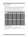
Chapter 1: Introduction
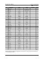
1.1 Product Overview
Although the X4 AC drive is small in size, it is big on performance. It is an economical yet powerful
solution for many industrial applications. It features remote communications capability (using
Modbus® protocol), a keypad for easy configuration, and standard NEMA 4X / IP66 and NEMA 12
/ IP55 enclosures that eliminate the need for mounting in a separate enclosure.
The X4 product family includes a wide variety of models to suit almost any input voltage
requirement. An ‘x’ in the following table indicates what models are currently available. Refer to
“Chapter 2: Technical Characteristics” on page 11 for help in interpreting model numbers.
Input Voltage
Horsepower
115 Vac
1 Phase
230 Vac
3 Phase
460 Vac
3 Phase
575 Vac
3 Phase
1
x
x
x
x
2
x
x
x
3
x
x
x
x
5
x
x
7.5
x
x
x
10
x
x
x
15
x
x
x
20
x
x
x
25
x
x
x
30
x
x
x
40
x
x
50
x
x
60
x
x
75
x
x
100
x
x
125
x
x
150
x
x
200
x
x
1.2 Overview of This Manual
This manual contains specifications, receiving and installation instructions, configuration,
description of operation, and troubleshooting procedures for X4 AC drive devices.
For experienced users, a Quick Start section begins on page 58. A summary of parameters begins on
page iii of this manual.
DPD00088A
-9-
© 2009 Vacon Incorporated All Rights Reserved
X4 AC Drive User’s Manual
Chapter 1: Introduction
1.3 User’s Manual Publication History
Date
Form Number
Nature of Change
June 2005
1428
First release
March 2006
1428B
Minor corrections throughout manual.
Clarification of technical information and specifications.
Added X4 models for Frame Size 2.
Reformatted to larger page-size document; separated appendices
from manual to be available on the web site (www.vacon.com).
August 2006
1428C
Minor corrections and enhancements throughout manual.
Added 40 and 50 HP models.
June 2007
1428D
Added 60-200 HP models, new parameters.
Minor corrections and reformatting throughout manual.
March 2008
1428E
Minor changes to format, copyright information, and logo
Minor corrections throughout manual
May 2008
1428F
Minor corrections throughout manual; added new EU Declaration
of Conformity
June 2008
1428G
Changed corporate information for Vacon Incorporated
November 2008
April 2009
DPD00088A
Changed installation diagrams to reflect changes in product;
DPD00088
changed photographs of product; added information to Chapter 2
(1st release under this
on current surges and voltage transients; deleted mention of
number)
Model X4C20300C; other minor changes and corrections.
DPD00088A
Revised EU Declaration of Conformity
- 10 -
© 2009 Vacon Incorporated All Rights Reserved
Chapter 2: Technical Characteristics
2.1
Interpreting Model Numbers
The model number of the X4 AC drive appears on the shipping carton label and on the technical data
label affixed to the model. The information provided by the model number is shown below:
X4 C 20 030 C
X4 Series
Torque:
C = Constant - Normal duty
Input Voltage:
1S = 115 Vac, Single-phase
20 = 230 Vac, Three-phase
40 = 460 Vac, Three-phase
50 = 575 Vac, Three-phase
Horsepower:
For example, 010 = 1.0 HP and 075 = 7.5 HP
Enclosure:
C = NEMA 4X / IP66, with keypad
D = NEMA 12 / IP55
DPD00088A
- 11 -
© 2009 Vacon Incorporated All Rights Reserved
X4 AC Drive User’s Manual
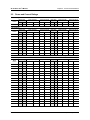
2.2
Chapter 2: Technical Characteristics
Power and Current Ratings
115 Vac Ratings
Model
number
Normal Duty
Input current (A)
Output current (A)
Heavy Duty
Input current (A)
Output current (A)
HP
kW
-
115 Vac
-
230 Vac
HP
kW
-
115 Vac
-
230 Vac
1
0.75
-
15
-
4.2
0.5
0.37
-
11
0
2.2
X4C1S010C
230 Vac Ratings
Model
number
Normal Duty
Input current (A)
Output current (A)
Heavy Duty
Input current (A)
Output current (A)
HP
kW
200 Vac
230 Vac
200 Vac
230 Vac
HP
kW
200 Vac
230 Vac
200 Vac
230 Vac
X4C20010C
1
0.75
5.6
4.8
4.8
4.2
0.5
0.37
2.9
2.5
2.5
2.2
X4C20020C
2
1.5
9
7.8
7.8
6.8
1
0.75
5.6
4.8
4.8
4.2
X4C20030C
3
2.2
12.7
11
11
9.6
2
1.5
9
7.8
7.8
6.8
X4C20050C
5
4
20.2
17.5
17.5
15.2
3
2.2
12.7
11
11
9.6
X4C20075C
7.5
5.5
29.2
25.3
25.3
22
5
4
20.2
17.5
17.5
15.2
X4C20100C
10
7.5
37.2
32.2
37.2
28
7.5
5.5
29.2
25.3
25.3
22
X4C20150C
15
11
52.1
46.4
48.3
42
10
7.5
37.2
32.2
37.2
28
X4C20200C
20
15
68.3
57.4
62.1
54
15
11
52.1
46.4
48.3
42
X4C20250C
25
18.5
82.3
73.8
78.2
68
20
15
68.3
57.4
62.1
54
NOTE: All 230 Vac models can be operated at single-phase, with 50% derating
460 Vac Ratings
Model
number
Normal Duty
Input current (A)
Output current (A)
Heavy Duty
Input current (A)
Output current (A)
HP
kW
380 Vac
460 Vac
380 Vac
460 Vac
HP
kW
380 Vac
460 Vac
380 Vac
460 Vac
X4C40010C
1
0.75
3
2.4
2.4
2.1
0.5
0.37
1.6
1.3
1.3
1.1
X4C40020C
2
1.5
5.2
3.9
3.8
3.4
1
0.75
3
2.4
2.4
2.1
X4C40030C
3
2.2
7.2
5.6
5.1
4.8
2
1.5
5.2
3.9
3.8
3.4
X4C40050C
5
4
12
8.8
8.9
7.6
3
2.2
7.2
5.6
5.1
4.8
X4C40075C
7.5
5.5
15
12.8
12
11
5
4
12
8.8
8.9
7.6
X4C40100C
10
7.5
19.7
16.3
15.6
14
7.5
5.5
15
12.8
12
11
X4C40150C
15
11
30.9
25.8
23
21
10
7.5
19.7
16.3
15.6
14
X4C40200C
20
15
40
33.3
31
27
15
11
30.9
25.8
23
21
X4C40250C
25
18
46.3
40
37
34
20
15
40
33.3
31
27
X4C40300C
30
22
57.5
47.8
43
40
25
18
46.3
40
37
34
X4C40400C
40
30
73.2
62.4
61
52
30
22
57.5
47.8
43
40
X4C40500C
50
37
82
78
71
65
40
30
73.2
62.4
61
52
X4C40600C
60
45
94
80
86
77
50
37
82
78
71
65
X4C40750C
75
55
114
99
105
96
60
45
94
80
86
77
X4C41000C 100
75
149
129
140
124
75
55
114
99
105
96
X4C41250D 125
90
168
156
168
156
100
75
140
124
140
124
X4C41500D 150
110
205
180
205
180
125
90
168
156
168
156
X4C42000D 200
132
240
240
240
240
150
110
205
180
205
180
DPD00088A
- 12 -
© 2009 Vacon Incorporated All Rights Reserved
X4 AC Drive User’s Manual
Chapter 2: Technical Characteristics
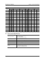
575 Vac Ratings
Model
number
Normal Duty
Input current (A)
Output current (A)
Heavy Duty
Input current (A)
Output current (A)
HP
kW
-
575 Vac
-
575 Vac
HP
kW
-
575 Vac
-
575 Vac
X4C50010C
1
0.75
-
2.0
-
1.7
0.5
0.37
-
1.2
-
0.9
X4C50020C
2
1.5
-
3.6
-
2.7
1
0.75
-
2.0
-
1.7
X4C50030C
3
2.2
-
5.0
-
3.9
2
1.5
-
3.6
-
2.7
X4C50050C
5
4
-
7.6
-
6.1
3
2.2
-
5.0
-
3.9
X4C50075C
7.5
5.5
-
10.4
-
9.0
5
4
-
7.6
-
6.1
X4C50100C
10
7.5
-
14.1
-
11.0
7.5
5.5
-
10.4
-
9.0
X4C50150C
15
11
-
23
-
17
10
7.5
-
14.1
-
11
X4C50200C
20
15
-
31
-
22
15
11
-
23
-
17
X4C50250C
25
18
-
37
-
27
20
15
-
31
-
22
X4C50300C
30
22
-
39.5
-
32
25
18
-
37
-
27
X4C50400C
40
30
-
49
-
41
30
22
-
39.5
-
32
X4C50500C
50
37
-
58
-
52
40
30
-
49
-
41
X4C50600C
60
45
-
68
-
62
50
37
-
58
-
52
X4C50750C
75
55
-
82
-
77
60
45
-
68
-
62
X4C51000C 100
75
-
107
-
99
75
55
-
82
-
77
X4C51250D 125
90
-
125
-
125
100
75
-
99
-
99
X4C51500D 150
110
-
144
-
144
125
90
-
125
-
125
X4C52000D 200
132
-
192
-
192
150
110
-
144
-
144
2.3
Environmental Specifications
Operating temperature
For 2003, 2005, 5005, 2030, 4030, and 5030 models:
–10 °C to +35 °C (14 °F to 95 °F)
For all other models:
–10 °C to +40 °C (14 °F to 104 °F)
Storage temperature
–20 °C to +65 °C (-4 °F to 149 °F)
Humidity
0% to 95% non-condensing
Altitude
1000 m (3300 ft) without derating
Maximum vibration
per EN50178 (1g @ 57-150 Hz)
Acoustic noise
80 dba sound power at 1 m (3 ft), maximum
Cooling
1 to 5 HP models: Natural convection
7.5 to 200.0 HP models: Forced air
Note: 575Vac 5 HP model has a fan.
DPD00088A
- 13 -
© 2009 Vacon Incorporated All Rights Reserved
X4 AC Drive User’s Manual
2.4
Chapter 2: Technical Characteristics
Electrical Specifications
Input voltage
X4C1Sx models: 115 Vac 1 phase, +/- 10%
X4C2x models: 200-230 Vac, 3 phase, +/- 15%
X4C4x models: 380-460 Vac, 3 phase, +/- 15%
X4C5x models: 575Vac, 3 phase, +/-15%
Line frequency
50 / 60 Hz ±2 Hz
Source kVA (maximum)
10 times the unit rated kVA (see note below)
DC bus voltage for:
Overvoltage trip
Dynamic brake activation
Nominal undervoltage (UV) trip
115 Vac models
406 Vdc
388 Vdc
199 Vdc
Control system
V/Hz or SVC
Carrier frequency = 1 - 16 kHz, programmable; 8 kHz max. for 125-200 HP
models
Output voltage
3-phase: 0 to 100% of incoming line (0-230 Vac for 115 Vac models)
Overload capacity
120% of rated normal duty rms current for 60 seconds
150% of rated heavy duty rms current for 60 seconds
Frequency range
0.1 to 400 Hz
Frequency stability
0.1 Hz (digital), 0.1% (analog) over 24 hours +/- 10 °C
Frequency setting
By keypad or by external signal
(Speed Pot 0 to 5 Vdc; 0 to 10 Vdc; 0 to 20 mA, or 4 to 20 mA)
OR by pulse train up to 100 kHz
230 Vac models
406 Vdc
388 Vdc
199 Vdc
460 Vac models
814 Vdc
776 Vdc
397 Vdc
575 Vac models
1017 Vdc
970 Vdc
497 Vdc
Note: Unit Rated kVA = rated Voltage x rated Current x 1.732
DPD00088A
- 14 -
© 2009 Vacon Incorporated All Rights Reserved
X4 AC Drive User’s Manual
2.5
Chapter 2: Technical Characteristics
Control Features Specifications
Vin1 reference input
0-5/10 Vdc, 0/4-20 mAdc (250 Ω load)
6FS pulse train input, 0-1/10/100 kHz pulse input, inverted function, 0-5-10 bipolar
input, broken wire detection. Span and offset adjustment.
Vin2 reference input
0-5/10 Vdc, 0-5-10 bipolar input, inverted function, broken wire detection, span and
offset adjustment. Programmable for frequency reference or current limit input.
Cin reference input
0/4-20 mAdc (50 Ω load), inverted function, span and offset adjustment.
Programmable for frequency reference or current limit input.
Reference voltage
10 Vdc (10 mAdc maximum)
Digital inputs - 10
Off=0 to 3 Vdc; On=10 to 32 Vdc (pullup logic), selectable between pullup and
pulldown logic
Digital supply voltage
24 Vdc (150 mAdc maximum)
Preset frequencies
3 inputs for seven preset frequencies (selectable)
Digital outputs
2 SPDT relay output - 130 Vac, 1 A/250 Vac, 0.5 A
2 open collector outputs 50 mA per device
Digital pulse train output
Open collector output pulse train proportional to output frequency
Vmet analog output
0 to 10 Vdc (5 mAdc maximum)
Imet analog output
0-20 mAdc output into a 500 Ω load (maximum)
DC holding / injection braking
At start, stop, by frequency with adjustable current level and time or continuous DC
injection by digital input.
Current limit
Four quadrant adjustable from 5 to 150%
Speed ramps
Primary and alternate adjustable from 0.1 to 3200.0 seconds
Voltage boost
Fixed boost adjustable from 0 to 50%, or auto boost in Vector mode
Voltage characteristic (V/Hz)
Linear, pump, fan or 2-piece linear
Timed overload
Adjustable inverse time trip (shear pin, 30 sec, 60 sec, 5 min), standard or inverterduty motors
Protective features
Overcurrent, overvoltage fault, ground fault, short circuit, dynamic brake overload,
drive temperature, power wiring fault, drive timed overload, input voltage quality,
overvoltage ridethrough
Program Sequence Logic
Controller (PSLC)
9-step PLC type functionality that can control speed, direction, and ramps based on
time, analog input, digital input, or pulse input.
Serial communications
Modbus Standard: RTU or ASCII
DPD00088A
- 15 -
© 2009 Vacon Incorporated All Rights Reserved
X4 AC Drive User’s Manual
2.6
Chapter 2: Technical Characteristics
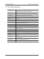
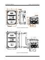
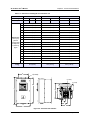
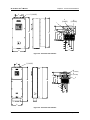
Dimensions and Weights
Table 2-1 lists dimensions and weights for the X4 frame size 0, 1, 2, and 3 models. Dimensions and
weights for the X4 frame size 4 and 5 models are shown in Table 2-2 on page 18.
See Figures 2-1, 2-2, 2-3, 2-4, 2-5, and 2-6 on pages 16 - 19 for locations of dimensions. Dimensions
A through Q are in inches / millimeters (in/mm). Weight is in pounds / kilograms (lb/kg).
Table 2-1: Dimensions and Weights for Frame Sizes 0 - 2
Frame
0
Voltage
115
Vac
Horsepower
1
Dimensions
inches (mm)
(See the
corresponding
X4 diagrams on
following pages
Weight
lb (kg)
1
230
Vac
460
Vac
1-3
2
230 Vac 460 Vac 575 Vac
5-7.5
5-10
1-10
230
Vac
460
Vac
575
Vac
10-15
15-30
15-30
A
9.47 (241)
12.01 (306)
17.38 (442)
B
6.50 (165)
8.72 (221)
10.75 (273)
C
6.08 (155)
6.51 (166)
7.91 (201)
D
8.45 (215)
11.03 (280)
16.50 (419)
E
5.69 (145)
7.88 (200)
9.76 (248)
F
0.28 (7.11)
0.28 (7.11)
0.41 (10)
G
3.84 (98)
4.05 (103)
4.72 (120)
H
2.77 (70)
N/A
N/A
J
1.93 (49)
2.31 (59)
2.88 (73)
K
2.85 (72)
3.94 (100)
4.84 (123)
L
3.75 (95)
5.56 (1.41)
6.88 (175)
M
0.88 (22)
0.88 (22)
1.38 (35)
N
N/A
N/A
1.13 (29)
P
N/A
N/A
N/A
Q
N/A
N/A
N/A
8.5 (3.85)
14.0 (6.35)
29.5 (13.38)
B
F
M
A
D
C
G
H
J
E
K
L
Figure 2-1: X4 Frame Size 0 Models
DPD00088A
- 16 -
© 2009 Vacon Incorporated All Rights Reserved
X4 AC Drive User’s Manual
Chapter 2: Technical Characteristics
B
F (4 places)
M (3 places)
A
D
C
G
J
E
K
L
Figure 2-2: X4 Frame Size 1 Models
B
F (4 PLACES)
M (2 PLACES)
N
D
A
C
G
J
E
K
L
Figure 2-3: X4 Frame Size 2 Models
DPD00088A
- 17 -
© 2009 Vacon Incorporated All Rights Reserved
X4 AC Drive User’s Manual
Chapter 2: Technical Characteristics
Table 2-2: Dimensions and Weights for Frame Sizes 3-5
Frame
3
4
5
Voltage
230 Vac
460 Vac
575 Vac
460 Vac
575 Vac
460 Vac
575 Vac
Horsepower
20-30
40-50
40-50
60-100
60-100
125-200
125-200
50.77 (1290)
51.02 (1296)
A
20.19 (513)
29.35 (745)
B
11.25 (286)
12.84 (326)
16.31 (414)
C
11.73 (314)
13.80 (351)
16.88 (429)
D
19.25 (489)
28.00 (711)
45.77 (1163)
E
7.88 (200)
7.88 (200)
7.65 (194)
F
0.28 (7.11)
0.42 (11)
0.42 (11)
Dimensions
inches (mm)
G
7.78 (198)
8.63 (219)
12.57 (319)
(See the
corresponding
X4 diagrams
on following
pages
H
N/A
8.26 (210)
11.10 (282)
J
0.65 (13)
0.53 (14)
0.20 (5)
K
2.29 (58)
2.69 (68)
2.32 (59)
L
3.95 (100)
3.94 (100)
3.82 (97)
M
1.69 (44)
2.44 (62)
2.94 (75)
N
0.88 (22)
0.88 (22)
0.88 (22)
P
5.60 (142)
5.19 (132)
5.32 (135)
Q
7.24 (184)
7.35 (187)
7.45 (189)
R
N/A
10.23 (260)
N/A
S
N/A
1.94 (49)
1.86 (47)
50.0 (22.68)
95.0 (43.10))
305.0 (138.35)
Weight
lb (kg)
E
F (8 PLACES)
N (2 PLACES)
M (2 PLACES)
D
A
C
G
J
K
L
P
B
Figure 2-4: X4 Frame Size 3 Models
DPD00088A
- 18 -
© 2009 Vacon Incorporated All Rights Reserved
X4 AC Drive User’s Manual
Chapter 2: Technical Characteristics
E
F (8 PLACES)
N
(2 PLACES)
S
A
M
(2 PLACES)
C
D
R
G
H
J
K
L
P
Q
B
Figure 2-5: X4 Frame Size 4 Models
E
F (8 PLACES)
N
(2 PLACES)
M
(2 PLACES)
C
G
A
D
S
H
J
K
L
P
Q
B
Figure 2-6: X4 Frame Size 5 Models
DPD00088A
- 19 -
© 2009 Vacon Incorporated All Rights Reserved
Chapter 3: Receiving and Installation
3.1 Preliminary Inspection
Before storing or installing the X4 AC drive, thoroughly inspect the device for possible shipping
damage. Upon receipt:
1. Remove the drive from its package and inspect exterior for shipping damage. If damage is apparent,
notify the shipping agent and your sales representative.
2. Remove the cover and inspect the drive for any apparent damage or foreign objects. (See Figure 3-1 on
page 22 for locations of cover screws.) Ensure that all mounting hardware and terminal connection
hardware is properly seated, securely fastened, and undamaged.
3. Read the technical data label affixed to the drive and ensure that the correct horsepower and input
voltage for the application has been purchased.
4. If you will be storing the drive after receipt, place it in its original packaging and store it in a clean, dry
place free from direct sunlight or corrosive fumes, where the ambient temperature is not less than -20 °C
(-4 °F) or greater than +65 °C (+149 °F).
CAUTION
EQUIPMENT DAMAGE HAZARD
Do not operate or install any drive that appears damaged.
Failure to follow this instruction can result in injury or equipment damage.
ATTENTION
RISQUE DE DOMMAGES MATÉRIELS
Ne faites pas fonctionner et n’installez pas tout variateur de vitesse qui semble être endommagé.
Si cette directive n’est pas respectée, cela peut entraîner des blessures corporelles ou des
dommages matériels.
3.2 Installation Precautions
Improper installation of the X4 AC drive will greatly reduce its life. Be sure to observe the following
precautions when selecting a mounting location. Failure to observe these precautions may void
the warranty! See the inside front cover of this manual for more information about the warranty.
•
Do not install the drive in a place subjected to high temperature, high humidity, excessive vibration,
corrosive gases or liquids, or airborne dust or metallic particles. See Chapter 2 for temperature,
humidity, and maximum vibration limits.
•
Do not mount the drive near heat-radiating elements or in direct sunlight.
•
Mount the drive vertically and do not restrict the air flow to the heat sink fins.
•
The drive generates heat. Allow sufficient space around the unit for heat dissipation. See “Dissipation
Requirements” on page 21.
DPD00088A
- 20 -
© 2009 Vacon Incorporated All Rights Reserved
X4 AC Drive User’s Manual
Chapter 3: Receiving and Installation
3.3 Dissipation Requirements
Table 3-1: Dissipation Requirement for X4 Models (Page 1 of 2)
Model
Required Dissipation for Models
Entirely Inside an Enclosure at Rated
Current, 3KHz Carrier Frequency (Watts)
Required Dissipation When Fins are
External to the Enclosure (Watts)
X4C1S010C
47
13
X4C20010C
48
14
X4C20020C
71
17
X4C20030C
92
16
X4C20050C
132
20
X4C20075C
177
23
X4C20100C
263
67
X4C20150C
362
68
X4C20200C
550
97
X4C20250C
653
96
X4C40010C
34
13
X4C40020C
46
16
X4C40030C
71
20
X4C40050C
91
21
X4C40075C
114
28
X4C40100C
155
30
X4C40150C
304
77
X4C40200C
393
76
X4C40250C
459
78
X4C40300C
458
77
X4C40400C
695
95
X4C40500C
834
100
X4C40600C
776
130
X4C40750C
988
135
X4C41000C
1638
155
X4C41250D
1656
353
X4C41500D
1891
372
X4C42000D
2302
382
DPD00088A
- 21 -
© 2009 Vacon Incorporated All Rights Reserved
X4 AC Drive User’s Manual
Chapter 3: Receiving and Installation
Table 3-1: Dissipation Requirement for X4 Models (Page 2 of 2)
Model
Required Dissipation for Models
Entirely Inside an Enclosure at Rated
Current, 3KHz Carrier Frequency (Watts)
Required Dissipation When Fins are
External to the Enclosure (Watts)
X4C50010C
32
15
X4C50020C
50
22
X4C50030C
66
21
X4C50050C
112
33
X4C50075C
159
37
X4C50100C
187
54
X4C50150C
334
124
X4C50200C
431
143
X4C50250C
528
154
X4C50300C
597
155
X4C50400C
742
160
X4C50500C
877
170
X4C50600C
766
200
X4C50750C
913
200
X4C51000C
1542
275
X4C51250D
1988
337
X4C51500D
2282
349
X4C52000D
3043
355
3.4 Cover Assembly and Torque Specifications
Figure 3-1 shows the locations of the X4 cover screws. The torque range for the X4 covers is 18-26
in/lbs.
Cover screw locations
Cover screw locations
Figure 3-1: X4 Cover Assembly and Screw Locations
Torque specifications for control terminals and power terminals are listed in “General Wiring
Information” on pages 25 and 26.
DPD00088A
- 22 -
© 2009 Vacon Incorporated All Rights Reserved
X4 AC Drive User’s Manual
Chapter 3: Receiving and Installation
3.5 Serial Number Label
All X4 AC drives are warranted for three years from date of manufacture, or two years from the date
of installation, whichever comes first. For a more detailed description of the warranty policy, visit
our web site at http://www.vacon.com. To determine if your drive is within the warranty time frame,
find the bar code label or look in the lower left of the technical nameplate. The serial number can be
broken down as follows:
yywwxxxx = yy...year of manufacture
ww...week of manufacture
xxxx...sequential number drive during that week
3.6 Conduit Usage
The X4 drive in the NEMA 4X / IP66 enclosure is rated for 1000 psi washdown from 6 inches. To
keep this rating, the use of a sealed conduit is required. The use of a Romex-type conduit will not
prevent water entry into the enclosure. If the approved conduit is not used, all warranty claims
against water damage will be void.
3.7 Condensation
The washdown process of an X4 drive may create a temperature and humidity change in and around
the drive. If the unit is mounted in a cool environment and washed down with higher-temperature
water, as the drive cools to room temperature, condensation can form inside the drive, especially
around the display. To prevent this from happening, avoid using sealed connectors around rubbercoated cables to seal the drive. These do not allow any air transfer and hence create a level of
condensation and humidity that exceeds the drive’s rating.
DPD00088A
- 23 -
© 2009 Vacon Incorporated All Rights Reserved
Chapter 4: Connections
DANGER
HAZARDOUS VOLTAGE
• Read and understand this manual in its entirety before installing or operating the X4 AC drive.
Installation, adjustment, repair, and maintenance of these drives must be performed by qualified
personnel.
• Disconnect all power before servicing the drive. WAIT 5 MINUTES until the DC bus capacitors
discharge.
• DO NOT short across DC bus capacitors or touch unshielded components or terminal strip screw
connections with voltage present.
• Install all covers before applying power or starting and stopping the drive.
• The user is responsible for conforming to all applicable code require-ments with respect to grounding
all equipment.
• Many parts in this drive, including printed circuit boards, operate at line voltage. DO NOT TOUCH. Use
only electrically-insulated tools.
Before servicing the drive:
• Disconnect all power.
• Place a “DO NOT TURN ON” label on the drive disconnect.
• Lock the disconnect in the open position.
Failure to observe these precautions will cause shock or burn, resulting in severe personal injury
or death.
DANGER
TENSION DANGEREUSE
• Lisez et comprenez ces directives dans leurs intégralité avant d’installer ou de faire fonctionner le
variateur de vitesse X4. L’installation, le réglage, les réparations et l’entretien des ces variateurs de
vitesse doivent être effectuées par du personnel qualifié.
• Coupez toutes les alimentations avant de travailler sur le variateur de vitesse. ATTENDEZ CINQ
MINUTES pour que la décharge des condensateurs du bus cc s’effectue.
• NE court-cuitez PAS les condensateurs du bus cc ou ne touchez pas aux composantes non blindées
ou aux connexions des vis du bornier si l’appareil est sous tension.
• Installez tous les couvercles avant de mettre le variateur de vitesse sous tension, de le mettre en
marche ou de l’arrêter.
• L’utilisateur est responsable de la conformité avec tous les codes électriques en vigueur concernant
la mise à la terre de tous les appareils.
• De nombreuses pièces de ce variateur de vitesse, y compris les cartes de circuits imprimés,
fonctionnent à la tension du secteur. N’Y TOUCHEZ PAS. N’utilisez que des outils dotés d’une
isolation électrique.
Avant tout entretien ou réparation sur le variateur de vitesse:
• Coupez toutes les alimentations.
• Placez une étiquette «NE PAS METTRE SOUS TENSION» sur le sectionneur du variateur de vitesse.
• Verrouillez le sectionneur en position ouverte.
Si ces précautions ne sont pas respectées, cela causera une électrocution ou des brûlures, ce
qui entraînera des blessures graves ou la mort.
DPD00088A
- 24 -
© 2009 Vacon Incorporated All Rights Reserved
X4 AC Drive User’s Manual
4.1
Chapter 4: Connections
Introduction
This chapter provides information on connecting power and control wiring to the X4 AC drive.
4.2
General Wiring Information
4.2.1 Wiring Practices
When making power and control connections, observe these precautions:
•
Never connect input AC power to the motor output terminals T1/U, T2/V, or T3/W. Damage
to the drive will result.
•
Power wiring to the motor must have the maximum possible separation from all other power wiring.
Do not run in the same conduit; this separation reduces the possibility of coupling electrical noise
between circuits.
•
Cross conduits at right angles whenever power and control wiring cross.
•
Good wiring practice also requires separation of control circuit wiring from all power wiring. Since
power delivered from the drive contains high frequencies which may cause interference with other
equipment, do not run control wires in the same conduit or raceway with power or motor wiring.
4.2.2 Considerations for Power Wiring
Power wiring refers to the line and load connections made to terminals L1/R, L2/S, L3/T, and T1/U,
T2/V, T3/W respectively. Select power wiring using these guidelines:
•
Use only UL-recognized wire.
•
Wire voltage rating must be a minimum of 300 V for 230 Vac systems and 600 V (Class 1 wire) for
460 or 575 Vac systems.
•
Wire gauge must be selected based on 125% of the continuous input current rating of the drive. Wire
gauge must be selected from wire tables for 75 °C insulation rating, and must be of copper construction.
The 230 V 7.5 and 15 HP models, and the 460 V 30 HP models require 90 °C wire to meet UL
requirements. See Chapter 2 for the continuous output ratings for the drive.
•
Grounding must be in accordance with NEC and CEC. If multiple X4 drives are installed near each
other, each must be connected to ground. Take care not to form a ground loop.
See Table 4-1 on page 26 and Table 4-2 on page 26 for information on power terminal wiring
specifications.
DPD00088A
- 25 -
© 2009 Vacon Incorporated All Rights Reserved
X4 AC Drive User’s Manual
Chapter 4: Connections
Table 4-1: X4 Power Terminal Wiring Specifications
Frame Size
Specifications
Torque Nom.
Torque Max.
Max. Wire Size
Strip Length
Size 0
12 in-lbs
13 in-lbs
12-24 AWG
5/16” (0.3125”)
Size 1
16 in-lbs
18 in-lbs
8-18 AWG
5/16” (0.3125”)
Size 2
30 in-lbs
6-8 AWG
3/8” (0.38”)
Size 3
35 in-lbs
3 AWG
Size 4
65 in-lbs
3/0 AWG
Size 5
132 in-lbs
400 MCM
Note: Wire type not specified by the manufacturer. Some types of wire may not fit within the constraints of the
conduit entry and bend radius inside the drive..
Table 4-2: User-Supplied Terminal Cross-Reference
Wire Size
Manufacturer
Manufacturer’s P/N
3 AWG
T&B
54107
2 AWG
T&B
54107
Manufacturer
Manufacturer’s P/N
1 AWG
T&B
54108
1/0 AWG
T&B
54152-TB
Burndy
YA25-L6BOX
2/0 AWG
T&B
54157
Burndy
YA26-L5BOX
3/0 AWG
T&B
54162-TB
Burndy
YA27-LBOX
4/0 AWG
Burndy
YA28-LBOX
250 MCM
Burndy
YA29-LBOX
300 MCM
Burndy
YA30-L
350 MCM
Burndy
YA31-L
400 MCM
Burndy
YA32-L1
4.2.3 Considerations for Control Wiring
Control wiring refers to the wires connected to the control terminal strip. Select control wiring as
follows:
•
Shielded wire is recommended to prevent electrical noise interference from causing improper operation
or nuisance tripping.
•
Use only UL recognized wire.
•
Wire voltage rating must be at least 300 V for 230 Vac systems. It must be at least 600 V for 460 or
575 Vac systems.
See Table 4-3 below for a summary of control terminal wiring specifications.
Table 4-3: X4 Control Wiring Specifications
DPD00088A
X4 Size / Models
Specifications
All Sizes / Models
4.4 in-lbs maximum torque
12-24 awg wire
9/32” strip length
- 26 -
© 2009 Vacon Incorporated All Rights Reserved
X4 AC Drive User’s Manual
4.3
Chapter 4: Connections
Input Line Requirements
4.3.1 Line Voltage
See “Power and Current Ratings” on page 12 for the allowable fluctuation of AC line voltage for
your particular X4 model. A supply voltage above or below the limits given in the table will cause
the drive to trip with either an overvoltage or undervoltage fault.
Exercise caution when applying the X4 AC drive on low-line conditions.
For example, an X4 2000 series unit will operate properly on a 208 Vac line, but the maximum
output voltage will be limited to 208 Vac. If a motor rated for 230 Vac line voltage is controlled by
this drive, higher motor currents and increased heating will result.
Therefore, ensure that the voltage rating of the motor matches the applied line voltage.
4.3.2 Line Capacity
If the source of AC power to the X4 AC drive is greater than 10 times the kVA rating shown in Table
4-4 below, an isolation transformer or line reactor is recommended. Consult the factory for
assistance in sizing the reactor.
Table 4-4: X4 Line Capacity (kVA)
Drive HP
1
2
3
5
7.5
10
15
20
25
30
40
50
60
75
100
125
150
200
Transformer
kVA
2
4
5
9
13
18
23
28
36
42
57
70
90
112
150
180
220
250
Note: X4 AC drive devices are suitable for use on a circuit capable of delivering not more than 65,000 rms
symmetrical amperes at 10% above the maximum rated voltage.
4.3.3 Phase Imbalance
Phase voltage imbalance of the input AC source can cause unbalanced currents and excessive heat
in the drive’s input rectifier diodes and DC bus capacitors. Phase imbalance can also damage motors
running directly across the line. The phase imbalance should not exceed 2% of the voltage rating.
CAUTION
EQUIPMENT DAMAGE HAZARD
Never use power-factor correction capacitors on motor terminals T1/U, T2/V, or T3/W of the X4 AC
drive. Doing so will damage the semiconductors.
Failure to follow this instruction can result in injury or equipment damage.
ATTENTION
RISQUE DE DOMMAGES MATÉRIELS
Ne raccordez jamais de condensateurs de correction du facteur de puissance aux bornes T1/U, T2/V, ou
T3/W du moteur du variateur de vitesse X4. Car cela endommagera les semiconducteurs.
Si cette directive n’est pas respectée, cela peut entraîner des blessures corporelles ou des
dommages matériels.
DPD00088A
- 27 -
© 2009 Vacon Incorporated All Rights Reserved
X4 AC Drive User’s Manual
Chapter 4: Connections
4.3.4 Single-phase Operation
X4 AC drive 230 Vac models ranging from 1 to 5 HP are designed for both three-phase and singlephase input power. If one of these models is operated with single-phase power, use any two line input
terminals. The output of the device will always be three-phase.
The safe derating of the X4 series of drives is 50% of the nominal current (HP) rating. Consult the
factory with the particular application details for exact derating by model.
4.3.5 Ground Fault Circuit Interrupters
X4 drives rated for 115 Vac are not designed to operate with ground fault circuit interrupters (GFCI).
The GFCI breakers are designed for residential use to protect personnel from stray currents to
ground. Most GFCI breakers will shut off at 5 mA of leakage. It is not uncommon for an AC drive
to have 30 to 60 mA of leakage.
4.3.6 Motor Lead Length
Vacon, Inc. recommends that the total lead length should not exceed the motor manufacturer’s
guidelines. Line disturbance and noise can be present in motor wiring of any distance. As a rule of
thumb, any non-inverter duty motor should have a reactor or filter added when the motor lead length
exceeds 150 feet. The carrier frequency for the drive should also be reduced using parameter 803
(PWM Frequency).
Nuisance trips can occur due to capacitive current flow to ground. These currents can cause shock
to personnel and can create problems within the motor. Care should be taken when working in these
areas.
Some applications can have a restricted lead length because of type of wire, motor type, or wiring
placement. Consult the factory and the motor manufacturer for additional information.
4.3.7 Using Output Contactors
Contactors in the output wiring of an AC drive may be needed as part of the approved safety circuit.
Problems can arise if these contactors are opened for the safety circuit and the drive is left in run
mode of operation. When the contactor is open, the drive is in a no-load, no-resistance state, but is
still trying to supply current to the motor. However, when the contactor closes, the drive sees the
motor resistance and instantly demands current. This inrush of current when the contactor closes can
fault or cause failure to the drive.
To prevent problems, interlock an auxiliary contact to the drive’s Run or Enable circuit to stop the
drive when the contactor opens. In this way, the drive will be disabled and no inrush will occur when
the contactor is closed again.
DPD00088A
- 28 -
© 2009 Vacon Incorporated All Rights Reserved
X4 AC Drive User’s Manual
4.4
Chapter 4: Connections
Terminals Found on the X4 Power Board
4.4.1 Description of the Terminals
Table 4-5 describes the X4 power terminals.
Table 4-5: Description of X4 Power Terminals
Terminal
Description
L1/R
L2/S
L3/T
These terminals are the line connections for input power. (Single-phase 115 and 230 Vac,
1 to 5 HP models connect to any two of these terminals.)
T1/U
T2/V
T3/W
These terminals are for motor connections.
Note that earth ground is on the terminal strip (see Figure 4-1 below). Dynamic brake (DB)
connections are not on the terminal strip, but on “fast on” (spade) connectors for models up to 30 HP,
and on the terminal strip for models 40 HP and larger. See page 32 for specific information about
dynamic braking.
Figure 4-1: X4 Power Terminals
DPD00088A
- 29 -
© 2009 Vacon Incorporated All Rights Reserved
X4 AC Drive User’s Manual
Chapter 4: Connections
Figure 4-2: Power Terminals on Higher-HP Models
4.4.2 Typical Power Connections
See Section 4.3 starting on page 27 for input line requirements.
Note that when testing for a ground fault, do not short any motor lead (T1/U, T2/V, or T3/W) back
to an input phase (L1/R, L2/S, or L3/T).
It is necessary to provide fuses and a disconnect switch for the input AC line in accordance with all
applicable electrical codes. The X4 AC drive is able to withstand a 150% overload for 60 seconds
for heavy duty rating, and 120% overload for normal duty rating.
The fusing and input protection of the drive must always meet UL, NEC (National Electric Code),
and CEC (Canadian Electric Code) requirements. All fuse ratings included in Table 4-6 below are
for reference only and do not supersede code requirements. The recommended supplier is Bussman.
Table 4-6: Fuse Ratings (Page 1 of 2)
Model Number
Fuse Size
115 Vac
JJS/JJN
Fuse Size
208 Vac
JJS/JJN
Fuse Size
230 Vac
JJS/JJN
Fuse Size
380 Vac
JJS
Fuse Size
460 Vac
JJS
Fuse Size
575 Vac
JJS
X4C1S010C
20
—
—
—
—
—
DPD00088A
X4C20010C
—
10
6
—
—
—
X4C20020C
—
15
10
—
—
—
X4C20030C
—
20
15
—
—
—
X4C20050C
—
30
25
—
—
—
X4C20075C
—
40
35
—
—
—
X4C20100C
—
50
40
—
—
—
X4C20150C
—
70
60
—
—
—
X4C20200C
—
90
80
—
—
—
X4C20250C
—
100
90
—
—
—
- 30 -
© 2009 Vacon Incorporated All Rights Reserved
X4 AC Drive User’s Manual
Chapter 4: Connections
Table 4-6: Fuse Ratings (Page 2 of 2)
Model Number
Fuse Size
115 Vac
JJS/JJN
Fuse Size
208 Vac
JJS/JJN
Fuse Size
230 Vac
JJS/JJN
X4C40010C
—
—
X4C40020C
—
—
X4C40030C
—
X4C40050C
DPD00088A
Fuse Size
380 Vac
JJS
Fuse Size
460 Vac
JJS
Fuse Size
575 Vac
JJS
—
6
6
—
—
10
6
—
—
—
10
10
—
—
—
—
15
15
—
X4C40075C
—
—
—
20
20
—
X4C40100C
—
—
—
25
20
—
X4C40150C
—
—
—
40
35
—
X4C40200C
—
—
—
50
40
—
X4C40250C
—
—
—
60
50
—
X4C40300C
—
—
—
80
60
—
X4C40400C
—
—
—
100
80
—
X4C40500C
—
—
—
110
100
—
X4C40600C
—
—
—
125
100
—
X4C40750C
—
—
—
150
125
—
X4C41000C
—
—
—
200
175
—
X4C41250D
—
—
—
225
200
—
X4C41500D
—
—
—
250
225
—
X4C42000D
—
—
—
300
300
—
X4C50010C
—
—
—
—
—
6
X4C50020C
—
—
—
—
—
6
X4C50030C
—
—
—
—
—
10
X4C50050C
—
—
—
—
—
10
X4C50075C
—
—
—
—
—
15
X4C50100C
—
—
—
—
—
20
X4C50150C
—
—
—
—
—
30
X4C50200C
—
—
—
—
—
40
X4C50250C
—
—
—
—
—
50
X4C50300C
—
—
—
—
—
50
X4C50400C
—
—
—
—
—
70
X4C50500C
—
—
—
—
—
80
X4C50600C
—
—
—
—
—
90
X4C50750C
—
—
—
—
—
110
X4C51000C
—
—
—
—
—
150
X4C51250D
—
—
—
—
—
175
X4C51500D
—
—
—
—
—
200
X4C52000D
—
—
—
—
—
250
- 31 -
© 2009 Vacon Incorporated All Rights Reserved
X4 AC Drive User’s Manual
4.5
Chapter 4: Connections
Dynamic Braking
The X4 AC drive is supplied with an integrated dynamic braking (DB) resistor, and is designed to
have adequate dynamic braking for most applications. In cases where short stopping times or high
inertia loads require additional braking capacity, install an external resistor.
Note: External braking cannot be added to Size 0 models. For Size 4 (60-100 HP) and Size 5 (125200 HP) models, additional external dynamic braking requires a kit that provides the connections to
the braking transistors. The XDBKITS4 and XDBKITS5 kits can be purchased through local
distributors. Frame Sizes 3 - 5 have both the DC positive and negative bus terminals available,
making the drive compatible with either an external resistor or a combination resistor / chopper type
of dynamic braking kit.
If an external resistor is used for dynamic braking (not applicable for Size 0 models), the internal
resistor must be disconnected. Internal DB resistors are connected with fast-on terminals. To
install an external resistor, first disconnect the internal DB resistor (or resistors in 460 and 575 Vac
models) and properly terminate the wires leading to it. Then connect the external resistor fast-on
terminals where the internal resistor had been connected.
Changes to parameter 410 (DB Config) must be made when using external DB resistors.
Verify with the manufacturer of the selected resistor that the resistor is appropriate for your
application. Contact Vacon’s Electronic Application Engineering (see inside front cover of this
manual) for further assistance with other possible sizing limitations.
Refer to Table 4-7 on page 32 for information about dynamic braking capacity for each X4 model.
Table 4-7: X4 Dynamic Braking Capacity (Page 1 of 2) (* Note that the asterisked X4 model numbers cannot
have external braking added)
Model
KW
Standard
Resistance
(ohms)
1S010*
.75
125
164%
--
--
--
Standard DB %
of Drive Power
Min. Allowed
Res. (ohms)
Max. Peak
Watts
Max. Ext. DB %
of Drive Power
20010*
.75
125
164%
--
--
--
20020*
1.5
125
82%
--
--
--
20030*
2.2
125
55%
--
--
--
20050
3.7
60
68%
43
3,555
95%
20075
5.5
60
45%
30
5,096
91%
20100
7.5
60
34%
27
5,662
76%
20150
11
60
23%
20
7,644
68%
20200
15
30
34%
10
15,288
102%
20250
18
30
27%
10
15,288
82%
40010*
.75
500
163%
--
--
--
40020*
1.5
500
82%
--
--
--
40030*
2.2
500
54%
--
--
--
40050
3.7
120
136%
100
6,084
163%
DPD00088A
- 32 -
© 2009 Vacon Incorporated All Rights Reserved
X4 AC Drive User’s Manual
Chapter 4: Connections
Table 4-7: X4 Dynamic Braking Capacity (Page 2 of 2) (* Note that the asterisked X4 model numbers cannot
have external braking added)
Model
KW
Standard
Resistance
(ohms)
40075
5.5
120
91%
75
40100
7.5
120
68%
75
8,112
109%
40150
11
120
45%
47
12,944
116%
40200
15
120
34%
47
12,944
87%
40250
18
120
27%
47
12,944
69%
40300
22
120
23%
39
15,600
70%
40400
29.8
60
34%
20
30,420
102%
40500
37.3
60
27%
20
30,420
82%
40600
45
60
23%
15
40,560
91%
40750
55
60
18%
10
60,840
109%
41000
75
60
14%
10
60,840
82%
41250
90
60
11%
10
60,840
65%
41500
110
60
9%
10
60,840
54%
42000
132
60
7%
10
60,840
41%
50010
.75
120
1058%
110
8,607
1154%
50020
1.5
120
529%
110
8,607
577%
50030
2.2
120
353%
110
8,607
385%
50050
3.7
120
212%
110
8,607
231%
50075
5.5
120
141%
91
10,404
186%
50100
7.5
120
106%
91
10,404
139%
50150
11
120
71%
62
15,269
136%
50200
15
120
53%
62
15,269
102%
50250
18
120
42%
62
15,269
82%
50300
22
120
35%
62
15,269
68%
50400
29.8
60
53%
24
39,447
132%
50500
37.3
60
42%
24
39,447
106%
50600
45
60
35%
15
63,115
141%
50750
55
60
28%
15
63,115
113%
51000
75
60
21%
20
63,115
85%
DPD00088A
Standard DB %
of Drive Power
Min. Allowed
Res. (ohms)
Max. Peak
Watts
Max. Ext. DB %
of Drive Power
8,112
145%
51250
90
60
17%
10
94,672
102%
51500
110
60
14%
10
94,672
85%
52000
132
60
11%
10
94,672
63%
- 33 -
© 2009 Vacon Incorporated All Rights Reserved
X4 AC Drive User’s Manual
4.6
Chapter 4: Connections
Terminals Found on the X4 Control Board
4.6.1 Description of the Control Terminals
Figure 4-3 shows the control terminals found on the I/O board of the X4 AC drive. See page 14 for
specifications. Table 4-8 on page 35 describes the control terminals.
The drive’s control terminals are referenced to earth ground through a resistor / capacitor network.
Use caution when connecting analog signals not referenced to earth ground, especially if the
communications port (J3) is being used. The J3 port includes a common reference that can be
connected to earth ground through the host PLC or computer.
Figure 4-3: X4 Control Terminals
DPD00088A
- 34 -
© 2009 Vacon Incorporated All Rights Reserved
X4 AC Drive User’s Manual
Chapter 4: Connections
Table 4-8: Description of X4 Control Terminals (Page 1 of 2)
Terminal
Vmet
Description
Analog output 1, which is a dedicated voltage output.
The default signal range is from 0 to 10 Vdc (5 mA maximum). It is proportional to the variable
configured by parameter 700 (Vmet Config) (see page 75). It may be calibrated while the drive
is running via parameter 701 (Vmet Span) (see page 75).
Imet
Analog output 2, which is a dedicated current output.
The default signal ranges from 0 to 20 mAdc (50 to 500 Ω). It is proportional to the variable
configured by parameter 702 (Imet Config) (see page 75).It may be calibrated while the drive is
running via parameters 704 (Imet Offset) and 703 (Imet Span) (see page 75).
Vin1
Analog Input 1, which is used to provide speed references.
The default input signal is 0 to 10 Vdc (the type of input signal is selected with parameter 205
(Vin1 Config); see page 63). Parameters 206 (Vin1 Offset) and 207 (Vin1 Span) may be used to
offset the starting value of the range and the size of the range, respectively; see page 63 for
more information.
If a 0 to 20 mAdc input signal is configured, the burden is 250 Ω. If a 0 to 10 Vdc input signal is
configured, the input impedance is 475 kΩ.
A potentiometer with a range of 1 to 10 kΩ is suggested for this input.
+10
Cin+ / Cin-
This terminal is a +10 Vdc source for customer-supplied potentiometers. The maximum load on
this supply cannot exceed 10 mAdc.
Current Input.
The default input signal is 4-20 mA, although this range may be adjusted by using parameters
209 (Cin Offset) (which configures an offset for the range) and 210 (Cin Span) (to reduce or
enlarge the range — for example, setting this parameter to 50% results in a range of 4-12 mA).
See page 64 for more information on these parameters.
The burden for this terminal is 50 Ω.
Vin2
Voltage Input 2, which is used to provide speed references.
The default input signal is 0 to 10 Vdc (the type of input signal is selected with parameter 211
(Vin2 Config); see page 64). Parameters 212 (Vin2 Offset) and 213 (Vin2 Span) may be used to
offset the starting value of the range and the size of the range, respectively; see page 64 for
more information.
A potentiometer with a range of 1 to 10 kΩ is suggested for this input.
Acom
DPD00088A
Common for the Analog Inputs and Outputs. Note that while there are three Acom (common)
terminals, they connect to the same electrical point.
+24
A source for positive nominal 24 Vdc voltage, and has a source capacity of 150 mA.
FWD
Forward Direction Selection terminal. This may be connected for two-wire maintained or threewire momentary operation.
REV
Reverse Direction Selection Terminal. This may be connected for two-wire maintained or threewire momentary operation.
R/J
Run/Jog Selector. When this terminal is connected to +24 or common (depending upon Active
Logic setting), momentarily connecting either FWD or REV to +24 results in a latched run mode
(3-wire operation).
MOL
Motor Overload input terminal. This requires a N/O or N/C contact for operation, referenced to
+24 or COM, depending on Active Logic setting.
- 35 -
© 2009 Vacon Incorporated All Rights Reserved
X4 AC Drive User’s Manual
Chapter 4: Connections
Table 4-8: Description of X4 Control Terminals (Page 2 of 2)
Terminal
Description
EN
Enable terminal. A jumper is placed between this terminal and the +24 terminal at the factory.
You may replace this with a contact, if desired. The circuit from EN to +24 must be closed for
the drive to operate.
Note that unlike all other terminals, this terminal cannot be configured for “pull-down logic.” That
is, a high input to this terminal is always regarded as true, and must be present for the drive to
operate.
Dcom
DI1-DI5
Digital Common for use with digital inputs and +24 internal power.
Digital inputs.
The function of a digital input is configured by the parameter with the same name as the digital
input (for example, DI2 is configured by parameter 722 (DI2 Configure); see page 77).
NC1
NO1
RC1
The first auxiliary relay.
The function of the relay is set by parameter 705 (Relay 1 Select) (see page 76); the default
setting is for the relay to activate when a fault occurs (Drv Fault).
Terminal NO1 is the normally-open contact, which closes when the relay is activated. Terminal
NC1 is the normally-closed contact, which opens when the relay is activated. Terminal RC1 is
the common terminal.
NC2
NO2
RC2
The second auxiliary relay.
The function of the relay is set by parameter 706 (Relay 2 Select) (see page 76); the default
setting is for the relay to activate when the drive is running (Drv Run).
Terminal NO2 is the normally-open contact; it will close when the relay is activated. RC2 is the
common terminal.
DO1
DO2
Digital Outputs 1 and 2.
DOP
Open collector transistor output that supplies a pulse train proportional to speed. The frequency
of the output is set by parameter 812 (Freq Ref Output) to either 6x or 48x the running
frequency. The output has a maximum rating of 28 Vdc and requires a pull-up resistor
(4.7 kOhms) if using the drive’s internal supply.
The function of the outputs is set by parameters 707 (DO1 Select) and 708 (DO2 Select). The
default setting for DO1 is Drive Ready; for DO2 it is At Speed. See page 76.
Note that if you are using a high-impedance meter to this terminal, the pull-up resistor value may
need to change. Please consult the factory for more information.
DPD00088A
- 36 -
© 2009 Vacon Incorporated All Rights Reserved
X4 AC Drive User’s Manual
Chapter 4: Connections
4.6.2 Typical Connection Diagrams for Digital Inputs
Typical connection for 2-wire control
Typical connection for 3-wire control
Figure 4-4: Connections for 2-wire and 3-wire Control
Table 4-9: Selection of Preset Speeds
PS3 (Bit 3)
PS2 (Bit 2)
PS1 (Bit 1)
Speed Selected
0
0
0
Normal reference speed as defined by parameters
201 (Input Mode) and 204 (Ref Select)
0
0
1
Preset frequency F1 (303-F1).
0
1
0
Preset frequency F2 (304-F2).
0
1
1
Preset frequency F3 (305-F3).
1
0
0
Preset frequency F4 (306-F4).
1
0
1
Preset frequency F5 (307-F5).
1
1
0
Preset frequency F6 (308-F6).
1
1
1
Maximum frequency (302, Max Frequency).
Figure 4-5: Connections for Preset Speeds
DPD00088A
- 37 -
© 2009 Vacon Incorporated All Rights Reserved
X4 AC Drive User’s Manual
Chapter 4: Connections
4.6.3 Typical Connection Diagrams for Analog Inputs
Figure 4-6: Connections for Speed Potentiometer
Figure 4-7: Connections for Process Signal
4.6.4 Typical Connection Diagrams for Analog Outputs
Figure 4-8: Connections for Process Meters
DPD00088A
- 38 -
© 2009 Vacon Incorporated All Rights Reserved
X4 AC Drive User’s Manual
Chapter 4: Connections
4.6.5 Modbus Connection Diagram
Figure 4-9: RS-485 Connector (Modbus) Pinout
4.7
Reducing Current Surges and Voltage Transients
Inrush currents to coils of magnetic contactors, relays, and solenoids associated with or near the
drive can induce high current spikes in the power and control wiring, causing faulty operation. If this
occurs, a snubber network consisting of a series resistor and capacitor for AC loads, or a freewheeling or flyback diode for DC loads, can be placed across the relay coil to prevent this condition.
The following component values should be used for 115 VAC or 230 VAC relays or solenoids.
For Main Circuit Contactors and Solenoids
C = 0.2 MFD, 500 VDC
R = 500
5 Watts
For Auxiliary Control Circuit Relays
C = 0.1 MFD, 500 VDC
AC
2 Watts
DC
+
Coil
R = 200
RC Type
Snubber
Coil
Freewheeling
Diode
-
Figure 4-10: Connection Diagram for AC and DC Relay Coils and Solenoids
For magnetic contactors, relays, and solenoids energized from a DC source, use a free-wheeling
diode of the high-speed, fast-recovery type. Connect the diode across the coil as shown above in
Figure 4-10. The diode current and voltage should be selected using the following formulae:
Diode Current Rating (A)
Diode Voltage Rating
DPD00088A
=
=
Coil Capacity (VA)
Rated Voltage of Coil (V)
Rated Voltage of Coil (V) x 2
- 39 -
© 2009 Vacon Incorporated All Rights Reserved
Chapter 5: Keypad Operation and Programming
5.1
Introduction
The X4 AC drive is pre-programmed to run a standard, 4-pole AC induction motor. For many
applications, the drive is ready for use right out of the box with no additional programming needed.
The digital keypad controls all operations of the unit. The ten input keys allow “press and run”
operation of the motor (Operation mode) and straightforward programming of the parameters
(Program mode)..
Figure 5-1: The X4 Keypad
To simplify programming, the parameters are grouped into three levels:
1. Enter Level 1 by pressing the Program (PROG) key at any time. Level 1 allows you to access
the most commonly used parameters.
2. Enter Level 2 by holding down the SHIFT key while pressing the PROG key. Level 2 allows
access to all X4 parameters, including those in Level 1, for applications which require more
advanced features.
3. Enter Macro mode by holding the Program (PROG) key down for more than 3 seconds. The
display then shows “Hold PROG for Macro Mode.” See Chapter 6, “Using Macro Mode,”
starting on page 49, for more information.
The summary of parameters found before the Table of Contents notes whether a parameter is in
Level 1. “Chapter 7: X4 Parameters” on page 59 gives full information about what level a
parameter is in.
Note that all parameters can be addressed by adding 40000 to the parameter number. For
example, parameter 201 (Input Mode) can be addressed by Modbus address 40201.
Want to get started quickly? See the “Quick Start” section on page 58.
DPD00088A
- 40 -
© 2009 Vacon Incorporated All Rights Reserved
X4 AC Drive User’s Manual
5.2
Chapter 5: Programming with the X4 Keypad
Keypad Operation
Parameter 201, Input Mode (see page 62), determines whether the X4 AC drive accepts its Run/
Stop and speed commands from the digital keypad or from the input terminals. Table 5-1 describes
the function of the keys in Operation mode.
Table 5-1: Function of Keys in Operation Mode (X4 Running or Stopped)
Initiates forward run when pressed momentarily. If the drive is running in reverse when FWD
is pressed, it will decelerate to zero speed, change direction, and accelerate to the set speed.
The green FWD designation in the key illuminates whenever a FWD command has been
given. When both the FWD and REV lights are on, the DC braking function is active.
Initiates reverse run when pressed momentarily. If the drive is running in forward when REV
is pressed, it will decelerate to zero speed, change direction, and accelerate to the set speed.
The green REV in the key illuminates whenever a REV command has been issued. When both
the FWD and REV lights are on, the DC braking function is active.
Causes a Ramp-to-Stop when pressed. Programmable to Coast-to-Stop by parameter 401,
Ramp Select (page 66). The red STOP indicator in the key illuminates whenever a STOP
command has been given. If the drive has stopped because of a fault, this indicator flashes to
call attention to the display. The STOP key also functions as a fault RESET key.
Press the JOG key to enter Jog mode. The green JOG indicator in the key illuminates when
the drive is in the JOG mode of operation. To jog the motor in either direction, press either the
FWD or REV (if REV is enabled in parameter 202). The motor will operate at the speed
programmed in parameter 303. To exit Jog mode, press the JOG key again.
When the drive is stopped, pressing this key increases the desired running speed. When the
drive is running, pressing this key increases the actual running speed in 0.1 Hz increments.
Holding the SHIFT key while pressing the INC (UP arrow) key moves the decimal place to the
left with each press (0.1 Hz, 1.0 Hz, 10.0 Hz increments).
When the drive is stopped, pressing this key decreases the desired running speed. When the
drive is running, pressing the DEC (down arrow) key decreases the actual running speed in
0.1 Hz increments. Holding the SHIFT key while pressing the DEC key moves the decimal
place to the right with each press (10.0 Hz, 1.0 Hz, 0.1 Hz increments).
NOTE: The operating speed for the drive is stored on Power Down.
Pressing this key while a parameter is displayed allows that parameter to have its value
changed by use of the INC and DEC (up and down arrow) keys. The P indicator flashes to
show that the parameter can be programmed. See also the descriptions for the INC and DEC
keys to see how they work with the SHIFT key.
The ENTER key has no function when the drive is running or stopped. ENTER can be used to
store the speed command so that it is saved through a power-down. To enable this function,
see the description for parameter 802 (Start Options) on page 78.
Whether the drive is running or stopped, pressing this key places the drive in Program mode.
See Table 5-2 on page 42 for more information on how this key functions.
Pressing this key toggles drive control between the LOCal and REMote control modes, as
selected by parameter 201 (Input Mode). It can be configured to shift:
•
•
•
the Run/Stop command (either FWD or REV)
the speed reference signal
both of the above
It can also be set to “disabled,” which is the factory setting. It will operate either in Stop mode
or while the drive is running. If power is removed and reapplied, the memory will retain the last
selected function.
DPD00088A
- 41 -
© 2009 Vacon Incorporated All Rights Reserved
X4 AC Drive User’s Manual
Chapter 5: Programming with the X4 Keypad
You can access Program mode by stopping the X4 drive and pressing the Program (PROG) key
for Level 1 access; or holding down SHIFT while pressing PROG for Level 2 access. Pressing and
holding the Enter key and then pressing the Program key will show only those parameters that have
been changed from the factory defaults. Table 5-2 describes the function of the keys in Program
mode.
Table 5-2: Function of Keys in Program Mode
Press this key to have the drive enter Program mode and have Level 1 parameters available. (To
access Level 2 parameters, hold down SHIFT while pressing this key; to access Macro mode, hold
down the PROG key for more than 3 seconds.) Once Program mode is active, pressing this key at
any time returns the drive to the Operation mode. If an Access Code has been programmed, it must
be entered to proceed with programming. See Parameter 811 (Access Code) (page 79).
NOTE: To see what parameters have changed from the factory default, press ENTER + PROG. If the display
flashes “Factory Defaults,” no parameters have changed.
In the Program mode, pressing this key scrolls forward through the parameters. If the P indicator is
flashing, it increases the value of the parameter. To change the scroll rate, hold the SHIFT key at
the same time to increase the scroll rate; release the SHIFT key to return to the normal scroll rate.
Press the ENTER key to store the new value.
In the Program mode, pressing this key scrolls backward through the parameters. If the P indicator
is flashing, it decreases the value of the parameter. To change the scroll rate, hold the SHIFT key
at the same time to increase the scroll rate; release the SHIFT key to return to the normal scroll rate.
Press the ENTER key to store the new value.
NOTE: If the P indicator on the keypad display is flashing, momentarily pressing and releasing both the INC
and DEC keys at the same time restores the parameter to the factory default value. Press ENTER to store the
new value.
Pressing this key while a parameter is displayed allows that parameter to have its value changed by
use of the INC and DEC (up and down arrow) keys. The P indicator flashes to show that the
parameter can be programmed. See also the descriptions for the INC and DEC keys to see how
they work with the SHIFT key.
This key must be pressed after the value of a parameter has been changed to store the new value.
The display will show “stored” for one second indicating that the new value has been entered into
memory.
NOTE: The X4 unit allows you to view only those parameters that have changed. If you press keypad keys ENTER
and PROGram simultaneously, only those parameters that have been changed from the factory defaults will be
shown.
Table 5-3: Function of Keys in Fault Mode
In Fault mode, pressing the INC (up arrow) and DEC (down arrow) keys allows the operator to view
the drive’s status immediately before the fault occurred. Use the INC or DEC keys to scroll through
the status parameters. Press the STOP (Reset) key to return to normal operation.
See “Chapter 8: Troubleshooting” on page 93 for information about viewing Advanced Fault Codes
and understanding error codes.
The red STOP key functions as a reset button when in Fault mode. If the drive has stopped because
of a fault, this light flashes to call attention to the display.
DPD00088A
- 42 -
© 2009 Vacon Incorporated All Rights Reserved
X4 AC Drive User’s Manual
5.3
Chapter 5: Programming with the X4 Keypad
LCD Displays
The X4 drive’s digital keypad display provides information such as source of drive control, status,
mode, and access rights.
5.3.1 Control
The first 3 characters of the display show the source of control for the drive:
Display Values
Meaning
LOC
Local control via the keypad
REM
Remote control from the terminal strip
SIO
Remote control via the RS485 Serial SIO Link
SQx
Control via the Program Sequencer
MEA
The Stator Resistance Measurement is armed
5.3.2 X4 Keypad Status and Warning Messages
Table 5-4 shows X4 keypad status messages that may appear during operation:
Table 5-4: Keypad Status States (Page 1 of 2)
Message
Meaning
Stopped
The drive is not spinning the motor or injecting DC voltage. The drive is ready to run when given the
proper signal.
FWD Accel
The drive is spinning the motor in the forward direction and the speed of the motor is increasing.
REV Accel
The drive is spinning the motor in the reverse direction and the speed of the motor is increasing.
FWD Decel
The drive is spinning the motor in the forward direction and the speed of the motor is decreasing.
REV Decel
The drive is spinning the motor in the reverse direction and the speed of the motor is decreasing.
Jog FWD
The drive is jogging in the forward direction.
Jog REV
The drive is jogging in the reverse direction.
FWD At Spd
The drive is spinning the motor in the forward direction and the speed of the motor is at the reference
frequency.
REV At Spd
The drive is spinning the motor in the reverse direction and the speed of the motor is at the reference
frequency.
Zero Speed
The drive has an active run signal but the motor is not spinning because the reference speed to the
drive must be 0.0 Hz.
DC Inject
Faulted
Reset-Flt
LS Lockout
Catch Fly
DPD00088A
The drive is injecting DC voltage into the motor.
The drive is faulted.
The drive is faulted, but has the possibility of being automatically reset.
Line-Start Lockout functionality has become active. This means there was an active run signal
during power-up or when a fault was reset. This run signal must be removed before the Line-Start
Lockout functionality will be removed.
The Catch on the Fly functionality is actively searching for the motor frequency.
- 43 -
© 2009 Vacon Incorporated All Rights Reserved
X4 AC Drive User’s Manual
Chapter 5: Programming with the X4 Keypad
Table 5-4: Keypad Status States (Page 2 of 2)
Message
Meaning
Forward
The drive is running forward without accelerating, decelerating or residing at the reference
frequency. This means that something is keeping the drive from the reference frequency (for
example, Current Limit).
Reverse
The drive is running in reverse without accelerating, decelerating or residing at the reference
frequency. This means that something is keeping the drive from the reference frequency (for
example, Current Limit).
Not Enabled
The drive is not allowed to run either because the digital input enable is not active or because
ARCTIC mode has shut down the run operation.
Volt Range
The drive has not met the input voltage voltage requirements that it needs to be able to run. In other
words, the Bus Voltage of the drive is either too low or too high.
Low Voltage
The drive has reached an undervoltage state.
Kpd Stop
A stop command was given from the keypad when the keypad was not the active control source. To
remove this condition, the run signal to the drive must be removed.
Table 5-5 shows X4 keypad warning messages that may appear during operation:
Table 5-5: Keypad Warnings
Message
Meaning
DB Active
The DB Resistor is being actively pulsed.
Curr Limit
The drive is operating in current limit.
HS Fan Err
Either the heatsink fan should be on and is off, or vice-versa.
Addr XXX
This is the node address of the drive when it receives a valid message through the IR port
address to another node. The XXX will be replaced with the node address.
High Temp
The temperature of either the heatsink or the control board is nearing a high temperature limit
that will fault the drive.
Low Temp
The temperature of either the heatsink or the control board is nearing a low temperature limit that
will fault the drive.
Vac Imblnce
Either the drive has lost an input phase or the input voltage is unbalanced more than 2%.
Power Supp
A power supply short occurred.
Seq Dwell
The sequencer is active, but the transition to the next step is halted.
Int Fan Err
Either the internal fan is on and should be off, or vice-versa.
DB OverTemp
The temperature of the DB Resistor is nearing a high temperature and will fault the drive.
ARCTIC Mode
The ARCTIC DB Resistor mode is actively pulsing the DB Resistor.
CPU Warning
A system error occurred in the software of the X4.
Mtr Measure
An RS Measurement is armed or active.
IR Active
Valid IR communications are occurring.
Seq Running
DPD00088A
The program sequencer functionality is active.
- 44 -
© 2009 Vacon Incorporated All Rights Reserved
X4 AC Drive User’s Manual
Chapter 5: Programming with the X4 Keypad
5.3.3 Rights
After Program mode is entered, the operator’s access rights are displayed:
Display Values
ACCESS
RIGHTS
P
This indicates that while in Programming mode, parameter data can be changed.
V
If the drive is in Run mode (FWD or REV) when the PROG key was pressed,
parameters can be viewed, but not changed.
The first character of the second line indicates if the particular parameter can be changed (P) or only
examined (V). If an attempt is made to change data while in the View (V) mode, the message **NO
ACCESS** will appear for one second.
5.3.4 Other Data
The top line gives 16-character description of the parameter being accessed. The parameter number
will flash when data is being changed. Up to 10 characters are used to display the information stored
in the parameter. Some parameters have a unit designator such as:
s
h
C
Hz
%
A
Seconds
Hours
Degrees centigrade
Hertz
Percent
Amperes
When the drive stops because of a fault trip, a unique error message will be displayed, along with
the flashing STOP indicator. “Pages,” or screens of information are available concerning the actual
fault and drive status.
“Chapter 8: Troubleshooting” on page 93 gives information about fault codes and troubleshooting.
5.4
Keypad Display Window
The keypad display provides information on drive operation and programming. Special symbols
provide further information about drive operation (see the following section). Figure 5-2 shows an
example of the X4 keypad display.
Figure 5-2: X4 Keypad Display
DPD00088A
- 45 -
© 2009 Vacon Incorporated All Rights Reserved
X4 AC Drive User’s Manual
5.5
Chapter 5: Programming with the X4 Keypad
Programming
5.5.1 Accessing Parameters
When PROG (or SHIFT+PROG) is pressed after application of power or a fault reset, parameter 201,
Input Mode, is always the first parameter displayed. Figure 5-3 shows a typical programming
display.
Figure 5-3: Typical Programming Display
If a different parameter is accessed and Program mode is exited, that parameter is the first one
displayed the next time Program mode is entered. The drive remembers a different “last parameter
accessed” for Levels 1 and 2.
5.5.2 Changing the Display Scroll Rate
Pressing the INC or DEC keys (up or down arrows) causes the display to scroll at a slow rate. To
increase the scroll rate, hold the SHIFT key at the same time that you press the INC key. Release
the SHIFT key to return to the slow scroll rate. This procedure works in all programming and
operation modes.
5.5.3 Programming Procedure
To program the value of a parameter, follow these steps:
1. Press the Program (PROG) key to enter Level 1 Program mode. To enter Level 2, press
SHIFT+PROG. The P indicator will appear on the display. You must enter one level of
programming or the other; you cannot switch between levels without exiting Program mode.
Note that some parameters cannot be changed in Run mode. For example, if you wish to program
parameter 201, Input Mode, you must stop the drive before beginning programming. Refer to the
Parameter Summary Table at the front of this manual to see which parameters cannot be changed in
Run mode (they appear as shaded entries in the table).
2.
3.
4.
5.
6.
Press the INC or DEC keys to access the desired parameter.
Press the SHIFT key to allow the value to be changed. The P indicator starts to blink.
Press the INC or DEC keys to select the new value.
Press the ENTER key to store the new value. The display shows “Stored” for one second.
Press the PROG key to exit the Program mode, or the INC or DEC keys to select a new
parameter.
To program a text parameter, follow these steps:
1. Like other parameters, text parameters use the INC/DEC (up/down arrow) and SHIFT keys
for editing. A line appears under the character that you are changing.
2. Press SHIFT to advance to the next character that you want to change.
3. Use the INC or DEC keys to change the character value.
4. Press ENTER to store the edited text.
DPD00088A
- 46 -
© 2009 Vacon Incorporated All Rights Reserved
X4 AC Drive User’s Manual
Chapter 5: Programming with the X4 Keypad
5.5.4 Restoring Factory Settings
Whenever a parameter’s value is being changed (noted by the P indicator flashing), the original
factory setting for that parameter may be restored by pressing and releasing both the INC and DEC
keys simultaneously and then pressing the ENTER key.
To restore ALL parameters to factory settings, or to recall a previously stored parameter set, see
parameter 801, Program Number (page 77).
5.5.5 Viewing Parameters That Have Changed
The X4 unit allows you to view only those parameters that have changed. If you press the ENTER
and PROG keys simultaneously, only those parameters that have been changed from the factory
defaults will be shown. Note that all parameters, regardless of Level 1 or 2 default location, will be
shown. If other parameters need to be changed, press the PROG key to exit this mode in either Level
1 or 2, as needed.
5.5.6 Using Macro Mode
A special Macro programming mode is available with the X4 series of AC drives. The Macro
programming mode allows you to customize the most common parameters for your application in
the Level 1 group. Macro mode provides special parameters for activating modes of operation by
macros, program sequencer, or serial communications.
Parameters that are important to the drive’s operation are also included in the Macro mode. Although
these parameters are also available with standard programming, the Macro mode allows you to
quickly and easily configure the drive with essential parameters.
See “Chapter 6: Using Macro Mode and Getting a Quick Start” on page 49, for detailed information
about using macros to program the X4 drive.
5.6
Measuring Stator Resistance (RS Measurement)
5.6.1 Activating Automatic RS Measurement Using the Keypad
1. Make sure there is no load applied to the motor and that the motor shaft is free to spin without
damage or injury.
2. Enter the Macro programming mode of the X4 keypad by pressing and holding the PROG
key until the parameter “Appl Macro” appears on the keypad. This takes about two seconds.
3. Scroll through the parameters of the X4 Macro programming mode and configure the
following parameters to the data provided on the nameplate of the motor:
• Rated Volt (509)
• Rated Mtr FLA (510)
• Rated Mtr RPM (511)
• Power Factor (515)
4. Change parameter “Find Mtr Data” (parameter 519) to a value of “Motor RS.” At this point,
the RS Measurement will be armed.
5. Exit the Macro programming mode by pressing the PROG key.
6. The Operate screen shows in two ways that an RS Measurement is ready to be made. First,
the Control path status field displays “MEA.” Second, a “Mtr Measure” warning flashes,
both of these signifying that a measurement is about to be taken.
DPD00088A
- 47 -
© 2009 Vacon Incorporated All Rights Reserved
X4 AC Drive User’s Manual
Chapter 5: Programming with the X4 Keypad
7. Start the RS Measurement by pressing the FWD key. The measurement can only be made
with the FWD key. The FWD / REV terminals and the REV key will not work.
8. The measurement will begin as the drive injects voltage to the motor at zero frequency. The
test lasts about two seconds.
9. If the test was successful, the drive will stop and return to the configured control path. The
“Motor RS” parameter will contain a new value that is the calculated resistance of the motor.
10. If the test was not successful, the drive will fault with a “RS Meas. Fail” message (Fault 34).
If the test fails, you may want to try the test again with a different “Rated Mtr FLA” or
different Current Limit percentage.
11. If the measurement process fails for any reason, it is possible to physically measure motor
resistance by using an ohmmeter and dividing the result by 2. Then enter this value manually
into parameter 514 (Motor RS).
5.6.2 Activating Automatic RS Measurement via Serial Link (Modbus)
1. Make sure there is no load applied to the motor and that the motor shaft is free to spin without
damage or injury.
2. Configure the following parameters to the data provided on the nameplate of the motor:
• Rated Volt (509)
• Rated Mtr FLA (510)
• Rated Mtr RPM (511)
• Power Factor (515)
3. Change parameter “Find Mtr Data” (519) to a value of “Motor RS.” At this point, the RS
Measurement will be armed.
4. Start the RS Measurement by writing a value of 0x0007 to parameter “SIO Cntl Word” (904).
5. The measurement begins as the drive injects voltage to the motor at zero frequency. The test
lasts about two seconds.
6. If the test was successful, the drive will stop and return to the configured control path. The
“Motor RS” parameter will contain a new value that is the calculated resistance of the motor.
7. If the test was not successful, the drive will fault with a “RS Meas. Fail” message (Fault 34).
If the test fails, you may want to try the test again with a different “Rated Mtr FLA” or
different Current Limit percentage.
8. If the measurement process fails for any reason, it is possible to physically measure motor
resistance by using an ohmmeter and dividing the result by 2. Then enter this value manually
into parameter 514 (Motor RS).
DPD00088A
- 48 -
© 2009 Vacon Incorporated All Rights Reserved
Chapter 6: Using Macro Mode and Getting a Quick Start
A special Macro programming mode is available with the X4 series of AC drives. The Macro
programming mode allows you to customize quickly the most common parameters for your
application in the Level 1 group. Macro mode provides special parameters for activating modes of
operation by macros, program sequencer, or serial communications.
Parameters important to the drive’s operation are also included in Macro mode. Although these
parameters are also available with standard programming, the Macro mode allows you to easily
configure the drive with essential parameters.
Macros configure what advanced functions will be active in the drive. A macro can also change the
default or visibility of a parameter within the programming levels. Parameter 490 (Appl Macro)
configures what macro will be active in the drive. Parameter 491 (Seq Appl) configures the
visibility of sequencer parameters and the time base of the sequencer. Parameter 492 (SIO Visible)
configures whether or not SIO parameters are visible. (See page 50.)
Note that all parameters can be addressed by adding 40000 to the parameter number. For
example, parameter 201 (Input Mode) can be addressed by Modbus address 40201.
6.1
Entering Macro Mode
To enter the Macro mode, press and hold the PROGram key for more than three seconds. The drive
then enters Macro mode and displays “Hold PROG for Macro Mode.” Following is a list of the
different macros available and their features. A description of parameters used in Macro mode begins
on page 50.
Factory
Fan
Fan w/ PI
Pump
Pump w/ PI
Vector
DPD00088A
The Factory macro provides a simple way to restore the factory default parameter listings.
The Fan macro provides a basic set-up for Fan applications. Parameters such as the V/Hz curve
and terminal strip operation are available in Level 1 programming.
The Fan w/ PI macro allows for a simple set-up for Fan applications requiring process control.
Parameters such as the V/Hz curve, terminal strip operation, and PI configuration parameters
are available in Level 1 programming.
The Pump macro provides a basic set-up for Pump applications. Parameters such as the V/Hz
curve and terminal strip operation are available in Level 1 programming.
The Pump w/ PI macro allows for a simple set-up for Pump applications requiring process
control. Parameters such as the V/Hz curve, terminal strip operation, and PI configuration
parameters are available in Level 1 programming.
The Vector macro activates the sensorless vector control algorithm. When an operation
requires low speed and high torque, this macro should be activated.
- 49 -
© 2009 Vacon Incorporated All Rights Reserved
X4 AC Drive User’s Manual
6.2
Chapter 6: Using Macro Mode / Quick Start
Description of Parameters Used in Macro Mode
Parameters 490, 491, and 492 are used only in the Macro mode. Parameters 509, 510, 511, 801, and
810 are used in both Macro and Level 2 programming. X4 parameters are described in “Chapter
7: X4 Parameters” on page 59 of this manual.
Default: Factory
490 Appl Macro
Range: text string
Macro
This parameter configures what macro will be active in the drive. A macro will change a default or visibility of a
parameter.
The following data values may be assigned to this parameter:
Macro
Description
Factory
Fan
Provides a simple way to restore factory default parameter listings.
Provides a basic set-up for Fan applications, including V/Hz curve and terminal strip operation in Level 1
programming.
Fan w/PI
Provides a simple set-up for Fan applications that require process control. Parameters such as V/Hz
curve, terminal strip operation, and PI configuration are available in Level 1 programming.
Pump
Provides a basic set-up for Pump applications, including V/Hz curve and terminal strip operation in Level
1 programming.
Pump w/PI
Provides a simple set-up for Pump applications requiring process control. Parameters such as V/Hz
curve, terminal strip operation, and PI configuration are available in Level 1 programming.
Vector
Activates the sensorless vector control algorithm. When an operation requires low speed and high torque,
this macro should be activated. Note that in Vector control, the drive automatically runs the Motor Rs
measurements when leaving PROGram mode.
Default: Disabled
491 Seq Appl
Range: text string
Macro
This parameter configures sequencer parameters are visible and the time base of the sequencer. The time base may
change depending on the timing loops used.
The following data values may be assigned to this parameter:
Macro Value
Description
Disabled
1sec Base
.1sec Base
.01sec Base
Sequencer disabled and parameters hidden.
Sequencer enabled and 1 second time base.
Sequencer enabled and 0.1 second time base.
Sequencer enabled and 0.01 second time base.
Default: No
492 SIO Visible
Range: text string
Macro
This parameter configures whether SIO parameters are visible.
The following data values may be assigned to this parameter:
Macro Value
Description
No
Yes
SIO parameters hidden.
SIO parameters visible.
509 Rated Mtr Volt
Default: Model dependent
Range: 100 V - 690 V
Level 2, Macro
The Rated Motor Voltage parameter configures the rated motor voltage, and allows a user to enter the rated voltage
from the motor nameplate to provide optimal control and protection. This is usually the amount of voltage delivered to
the motor terminals at the setting of parameter 503 (V/Hz Knee Freq).
510 Rated Mtr FLA
Default: ND Rating
Range: 50% of ND rating - 200% of ND rating
Level 2, Macro
The Rated Motor FLA parameter allows a user to enter the rated FLA from the motor nameplate to provide optimal
control and protection. This parameter should be configured to the value on the nameplate of the motor, as that value
is used in calculating the percentage of current at which the drive is operating.
For information on motor timed overload operation, and how parameter 510 works with it, see page 74.
DPD00088A
- 50 -
© 2009 Vacon Incorporated All Rights Reserved
X4 AC Drive User’s Manual
Chapter 6: Using Macro Mode / Quick Start
Range: 0-24000 rpm
Level 2, Macro
Default: 1750 rpm
511 Rated Mtr RPM
This parameter replaces the slip compensation parameter setting of the drive so the user does not need to calculate it.
Default: Model-dependent
514 Motor RS
Range: 0.00-655.35 Ohms
Level 2
This parameter allows direct entry of the Stator Resistance (Rs) of the motor for better vector performance. The motor
manufacturer can provide this information, or you can physically measure this value with an ohmmeter. From the lineto-line measurement of motor resistance, enter half the measured value. See “Measuring Stator Resistance (RS
Measurement)” on page 47.
Range: 0.50 - 1.00
Level 2
Default: 0.80
515 Power Factor
This parameter allows direct entry of the motor’s power factor for better vector performance. The motor manufacturer
can provide this information.
Range: text string
Macro
Default: Not Active
519 Find Mtr Data
This parameter activates the drive’s ability to measure the stator resistance of the attached motor. The automatic stator
resistance measurement can be performed either through the keypad or through the serial link. See “Measuring Stator
Resistance (RS Measurement)” on page 47 for more information about this parameter. The following data values may
be assigned:
Parameter Value
Not Active
Motor RS
801 Program Number
Description
No stator RS measurement.
Automatic RS measurement using macro procedure.
Range: 0 to 9999
Level 2, Macro
Default: 0
This parameter (Special Program Number) provides a method of enabling hidden functions in the drive and storing
parameters to the customer set.
Data Value
0
1
2
3
4
810 Language
Special Function Configured
Standard program
Reset all parameters to factory default values (display = SETP).
Store customer parameter values (display = STOC).
Load customer parameter values (display = SETC).
Swap active parameters with customer stored settings.
Range: text string
Level 2, Macro
Default: English
This parameter configures the language in which text strings will be displayed.
The following data values may be assigned to this parameter:
Parameter Value
English
Spanish
German
Italian
French
DPD00088A
- 51 -
© 2009 Vacon Incorporated All Rights Reserved
X4 AC Drive User’s Manual
6.3
Chapter 6: Using Macro Mode / Quick Start
Macro Mode Applications and Included Parameters
The tables below list the different applications and the Level 1 parameters included in the macro for
that application. The Factory Application macro is the core package (listed in Table 6-1); the other
macros include the Factory Application macro parameters as well as the ones listed in their
respective tables (Tables 6-2, 6-3, 6-4, 6-5, and 6-6). The macro mode applications are as follows:
Factory Application (Table 6-1)
Fan Application (Table 6-2)
Fan with PI Application (Table 6-3)
Pump Application (Table 6-4)
Pump with PI Application (Table 6-5)
Vector Application (Table 6-6)
Table 6-1: Factory Application Macro
DPD00088A
Para. #
Parameter Name
Default
See Page
001
Model Number
Read-only
60
010
Last Fault
Read-only
60
102
Output Freq
Read-only
61
103
Output Voltage
Read-only
61
104
Output Current
Read-only
61
105
Drive Load
Read-only
61
106
Load Torque
Read-only
61
107
Drive Temp
Read-only
61
111
DC Bus Voltage
Read-only
61
201
Input Mode
Local Only
62
202
Rev Enable
Forward
62
301
Min Frequency
0.0 Hz
65
302
Max Frequency
60.0 Hz
65
303
Preset Freq 1
5.0 Hz
65
402
Accel Time 1
5.0 sec
66
403
Decel Time 1
5.0 sec
66
502
Voltage Boost
0.0%
69
610
Timed OL Select
Std Ind 60s
74
700
Vmet Config
Freq Out
75
705
Relay 1 Select
Drv Fault
76
706
Relay 2 Select
Drive Run
76
- 52 -
© 2009 Vacon Incorporated All Rights Reserved
X4 AC Drive User’s Manual
Chapter 6: Using Macro Mode / Quick Start
Table 6-2: Fan Application Macro (Core Factory Application from Table 6-1, plus the following parameters)
DPD00088A
Para. #
Parameter Name
Default
See Page
203
Stop Key Remote
Coast
62
204
Ref Select
Vin1
63
205
Vin1 Config
0-10 V
63
206
Vin1 Offset
0.00%
63
207
Vin1 Span
100.00%
64
406
DC Inject Config
DC at Start
67
501
V/Hz Select
Fan Fixed
69
504
Skip Freq Band
0.2 Hz
70
505
Skip Freq 1
0.0 Hz
70
608
Restart Number
0
74
609
Restart Delay
60 sec
74
702
Imet Config
Current Out
75
703
Imet Span
100.0%
75
704
Imet Offset
0.0%
75
721
DI1 Configure
Preset 1
77
722
DI2 Configure
Preset 2
77
723
DI3 Configure
Preset 3
77
724
DI4 Configure
Ref Switch
77
725
DI5 Configure
Fault Reset
77
803
PWM Frequency
16.0 kHz
78
804
Display Mode
Output Freq
78
- 53 -
© 2009 Vacon Incorporated All Rights Reserved
X4 AC Drive User’s Manual
Chapter 6: Using Macro Mode / Quick Start
Table 6-3: Fan with PI Application Macro (Core Factory Application from Table 6-1, plus the following
parameters)
DPD00088A
Para. #
Parameter Name
Default
See Page
203
Stop Key Remote
Coast
62
204
Ref Select
Vin1
63
205
Vin1 Config
0-10 V
63
206
Vin1 Offset
0.00%
63
207
Vin1 Span
100.00%
64
208
Cin Config
0-20 mA 50
64
209
Cin Offset
0.0%
64
210
Cin Span
100.0%
64
211
Vin2 Config
0-10 V
64
212
Vin2 Offset
0.00%
64
213
Vin2 Span
100.00%
64
401
Ramp Select
ART-DI
66
406
DC Inject Config
DC at Start
67
501
V/Hz Select
Fan Fixed
69
504
Skip Freq Band
0.2 Hz
70
70
505
Skip Freq 1
0.0 Hz
608
Restart Number
0
74
609
Restart Delay
60 sec
74
702
Imet Config
Current Out
75
703
Imet Span
100.0%
75
704
Imet Offset
0.0%
75
721
DI1 Configure
Preset 1
77
722
DI2 Configure
Preset 2
77
77
723
DI3 Configure
Preset 3
724
DI4 Configure
Ref Switch
77
725
DI5 Configure
PI Enable
77
803
PWM Frequency
16.0 kHz
78
804
Display Mode
Output Freq
78
850
PI Configure
No PI
80
851
PI Feedback
Vin1
80
852
PI Prop Gain
0
80
853
PI Int Gain
0
81
854
PI Feed Gain
1000
81
857
PI High Corr
100.00
81
858
PI Low Corr
0.00%
81
- 54 -
© 2009 Vacon Incorporated All Rights Reserved
X4 AC Drive User’s Manual
Chapter 6: Using Macro Mode / Quick Start
Table 6-4: Pump Application Macro (Core Factory Application from Table 6-1, plus the following
parameters)
DPD00088A
Para. #
Parameter Name
Default
See Page
203
Stop Key Remote
Coast
62
204
Ref Select
Vin1
63
205
Vin1 Config
0-10 V
63
206
Vin1 Offset
0.00%
63
207
Vin1 Span
100.00%
64
401
Ramp Select
ART-DI
66
501
V/Hz Select
Pump Fxd
69
608
Restart Number
0
74
609
Restart Delay
60 sec
74
702
Imet Config
Current Out
75
703
Imet Span
100.0%
75
704
Imet Offset
0.0%
75
721
DI1 Configure
Preset 1
77
722
DI2 Configure
Preset 2
77
723
DI3 Configure
Preset 3
77
724
DI4 Configure
Ref Switch
77
725
DI5 Configure
Fault Reset
77
803
PWM Frequency
16.0 kHz
78
804
Display Mode
Output Freq
78
- 55 -
© 2009 Vacon Incorporated All Rights Reserved
X4 AC Drive User’s Manual
Chapter 6: Using Macro Mode / Quick Start
Table 6-5: Pump with PI Application Macro (Core Factory Application from Table 6-1, plus the following
parameters)
DPD00088A
Para. #
Parameter Name
Default
See Page
203
Stop Key Remote
Coast
62
204
Ref Select
Vin1
63
205
Vin1 Config
0-10 V
63
206
Vin1 Offset
0.00%
63
207
Vin1 Span
100.00%
64
208
Cin Config
0-20 mA 50
64
209
Cin Offset
0.0%
64
210
Cin Span
100.0%
64
211
Vin2 Config
0-10 V
64
212
Vin2 Offset
0.00%
64
213
Vin2 Span
100.00%
64
401
Ramp Select
ART-DI
66
406
DC Inject Config
DC at Stop
67
501
V/Hz Select
Pump Fxd
69
504
Skip Freq Band
0.2 Hz
70
505
Skip Freq 1
0.0 Hz
70
608
Restart Number
0
74
609
Restart Delay
60 sec
74
702
Imet Config
Current Out
75
703
Imet Span
100.0%
75
704
Imet Offset
0.0%
75
721
DI1 Configure
Preset 1
77
722
DI2 Configure
Preset 2
77
723
DI3 Configure
Preset 3
77
724
DI4 Configure
Ref Switch
77
725
DI5 Configure
PI Enable
77
803
PWM Frequency
16.0 kHz
78
804
Display Mode
Output Freq
78
850
PI Configure
No PI
80
851
PI Feedback
Vin1
80
852
PI Prop Gain
0
80
853
PI Int Gain
0
81
854
PI Feed Gain
1000
81
857
PI High Corr
100.00
81
858
PI Low Corr
0.00%
81
- 56 -
© 2009 Vacon Incorporated All Rights Reserved
X4 AC Drive User’s Manual
Chapter 6: Using Macro Mode / Quick Start
Table 6-6: Vector Application Macro (Core Factory Application from Table 6-1, plus the following
parameters)
DPD00088A
Para. #
Parameter Name
Default
501
V/Hz Select
Vector
See Page
69
509
Rated Mtr Volt
Model dependent
70
510
Rated Mtr FLA
ND rating
70
511
Rated Mtr RPM
1750 rpm
70
514
Motor RS
Model dependent
70
515
Power Factor
0.8
70
516
Slip Comp Enable
No
71
519
Find Mtr Data
Not Active
71
520
Filter FStator
8 mS
71
521
Start Field En
No
71
522
Filter Time Slip
100 mS
71
523
Id Percent
Read-only
72
524
Iq Percent
Read-only
72
803
PWM Frequency
3.0 kHz
78
804
Display Mode
Std Display
78
- 57 -
© 2009 Vacon Incorporated All Rights Reserved
X4 AC Drive User’s Manual
6.4
Chapter 6: Using Macro Mode / Quick Start
Quick Start
The following procedure is for operators using simple applications, who would like to get started
quickly. Be sure to read and understand all the sections in this chapter before proceeding with these
instructions. If you are using remote operators, substitute the speed potentiometer for the INC and
DEC keys (up and down arrows), and the remote Run/Stop switch for the FWD key in the following
instructions.
CAUTION
IMPROPER EQUIPMENT COORDINATION
Verify that proper voltage is connected to the drive before applying power.
Failure to observe this instruction can result in injury or equipment damage.
ATTENTION
MAUVAISE COORDINATION DES APPAREILS
Vérifiez que l’onduleur est raccordée à la bonne tension avant de le mettre sous tension.
Si cette directive n’est pas respectée, cela peut entraîner des blessures corporelles ou des
dommages matériels.
1.
Follow all precautions and procedures in “Chapter 3: Receiving and Installation” on page 20.
2.
Find the motor nameplate, and using parameters 509 (Rated Mtr Volt), 510 (Rated Mtr FLA), 511
(Rated Mtr RPM), and 515 (Power Factor), set up the motor parameters appropriately. Parameter 514
(Motor RS) should also be set up accurately so the drive can run its routine to measure motor stator
resistance. (See “Measuring Stator Resistance (RS Measurement)” on page 47.)
3.
Apply AC power to the input terminals. For about 2 seconds the display will show all segments active.
The display then changes to zeros.
4.
The factory settings are for keypad-only operation in the forward direction—that is, the REV key is
disabled. Press the FWD key, which causes the FWD indicator to illuminate.
5.
Press the INC key to increase the desired running frequency. When the display gets to 0.1 Hz, the drive
starts to produce an output.
6.
When the motor starts to turn, check the rotation. If the motor is turning in the wrong direction, press
STOP, remove AC power, and wait for all indicators to go out. After the STATUS indicator has gone out,
reverse any two of the motor leads at T1/U, T2/V, or T3/W.
7.
The X4 drive is preset to run a typical NEMA B 4-pole induction motor to a maximum speed of 60.0 Hz
with both acceleration and deceleration times set to 5.0 seconds.
8.
Use the INC and DEC keys to set the proper running speed of the motor and the FWD and STOP keys
to control its operation.
Note that the X4 external cooling fans operate continuously for the first five minutes of power-up
time; after this point, they operate only as needed to control the operating temperature of the drive.
DPD00088A
- 58 -
© 2009 Vacon Incorporated All Rights Reserved
Chapter 7: X4 Parameters
7.1
Introduction
The X4 AC drive incorporates a comprehensive set of parameters that allow you to configure the
device to meet the requirements of your particular application.
Note that pressing the PROG key enters Level 1 programming. Press SHIFT+PROG to enter Level
2 programming. Press ENTER+PROG to show only those parameters that have changed from the
factory default values.
This chapter describes the available parameters and the values that may be assigned to them. The
parameter summary table at the front of this manual provides a summary of all parameters including
their ranges and default values.
Note that all parameters can be addressed by adding 40000 to the parameter number. For
example, parameter 201 (Input Mode) can be addressed by Modbus address 40201.
7.2
Level 1 Parameters
The most commonly configured X4 parameters are stored in a group named Level 1. This group is
easily accessed by pressing the PROG key as described in “Chapter 5: Keypad Operation and
Programming” on page 40. The following table lists the parameters in this group; for further
information on the parameter, please turn to the indicated page.
Table 7-1: Parameters Available in Level 1 Programming (Factory Macro)
DPD00088A
Para. #
Parameter Name
See
Page
Para. #
Parameter Name
See
Page
001
Model Number
60
303
Preset Freq 1
65
010
Last Fault
60
402
Accel Time 1
66
102
Output Freq
61
403
Decel Time 1
66
103
Output Voltage
61
502
Voltage Boost
69
104
Output Current
61
610
Timed OL Select
74
105
Drive Load
61
700
Vmet Config
75
106
Load Torque
61
705
Relay 1 Select
76
107
Drive Temp
61
706
Relay 2 Select
76
111
DC Bus Voltage
61
201
Input Mode
62
202
Rev Enable
62
301
Min Frequency
65
302
Max Frequency
65
- 59 -
© 2009 Vacon Incorporated All Rights Reserved
X4 AC Drive User’s Manual
7.3
Chapter 7: X4 Parameters
Description of Parameters
Table 7-2 lists the X4 parameters in the order in which they appear in the keypad display. For each
parameter, the table lists the default value and range and also describes the use of the parameter.
Table 7-2: Description of X4 Parameters (Page 1 of 25)
001 Model Number
Range: text string
Level: 1,2
Read-Only
Parameter 001, the Model Number parameter, contains the portion of the X4 model number related to voltage and
horsepower. The number format is vvhhf, where vv is the code for the input voltage (19=115 Vac single-phase; 20=230
Vac, three-phase; 40=460 Vac, three-phase; 50=575 Vac, three-phase); hh is horsepower; and f is the fractional part
of the horsepower. Example: 20020 = 230 Vac, three-phase, 2.0 HP model.
002 Software Rev
Range: 0.00-99.99
Level: 2
Read-Only
Parameter 002, the Software Revision parameter, displays the software revision that is installed in the drive.
Options: 0.00-99.99
003 Rated Current
Range: 0.0-200.0 A
Level: 2
Read-Only
Parameter 003, the Rated Current parameter, displays the normal duty current rating of the model of drive.
005 Serial No 1
Range: 0-65535
Level: 2
Read-Only
Parameter 005, Serial No 1, contains a number that corresponds to the year and week in which the drive was
manufactured.
006 Serial No 2
Range: 0-65535
Level: 2
Read-Only
Parameter 006, Serial No 2, contains a number that determines the number of the drive that was manufactured during
the week of Serial No 1.
Options: 0.00-99.99
010 Last Fault
Range: text string
Level: 1,2
Read-Only
Parameter 010, Last Fault, lists the fault that occurred most recently.
For more information, refer to Chapter 8, Troubleshooting, beginning on page 93.
025 4th Fault
Range: text string
Level: 2
Read-Only
Parameter 025, 4th Fault, lists the fault that occurred 1 before the last fault.
For more information, refer to Chapter 8, Troubleshooting, beginning on page 93.
040 3rd Fault
Range:text string
Level: 2
Read-Only
Parameter 040, 3rd Fault, lists the fault that occurred 2 before the last.
For more information, refer to Chapter 8, Troubleshooting, beginning on page 93.
055 2nd Fault
Range: text string
Level: 2
Read-Only
Parameter 055, 2nd Fault, lists the fault that occurred 3 before the last.
For more information, refer to Chapter 8, Troubleshooting, beginning on page 93.
070 1st Fault
Range:text string
Level: 2
Read-Only
Parameter 070, 1st Fault, lists the fault that occurred 4 before the last.
For more information, refer to Chapter 8, Troubleshooting, beginning on page 93.
DPD00088A
- 60 -
© 2009 Vacon Incorporated All Rights Reserved
X4 AC Drive User’s Manual
Chapter 7: X4 Parameters
Table 7-2: Description of X4 Parameters (Page 2 of 25)
102 Output Freq
Range: 0.0 to 400.0 Hz
Levels 1,2
Read-Only
Parameter 102, the Output Frequency parameter, shows the frequency being applied to the motor connected to the
drive (ramp).
103 Output Voltage
Range: 0 to 600 V
Levels 1,2
Read-Only
Parameter 103, the Output Voltage parameter, displays the output voltage of the drive.
104 Output Current
Range: 0.0 to 200.0 A
Levels 1,2
Read-Only
Parameter 104, the Output Current parameter, displays the output current of the drive.
105 Drive Load
Range: -200.0% to 200.0%
Levels 1,2
Read-Only
Parameter 105, the Drive Load parameter, shows the percentage torque of the drive when operating below the knee
frequency. It displays Load Torque if the frequency is below FKNEE, and displays Power if above FKNEE.
The output current is measured with the motor power factor applied to an accuracy of ±20%.. The parameter value is
positive when the motor is pulling a load (“motoring mode”) and negative when being pulled by a load (“regenerative
mode”).
106 Load Torque
Range: -200.0%-200.0%
Levels 1,2
Read-Only
Parameter 106, the Load Torque parameter, displays the load torque of the drive.
107 Drive Temp
Range: -20.0 to 200.0 °C
Levels 1,2
Read-Only
Parameter 107, the Drive Temp parameter, shows the actual temperature of the drive’s heatsink. The drive will fault
when the internal temperature reaches 85°C.
108 Total Run Time
Range: 0.0 - 6553.5 h
Level: 2
Read-Only
Parameter 108, Total Run Time, is a resettable timer for drive operation. To reset the timer, enter 10 in parameter 801,
Program Number.
109 Power On Hours
Range: 0 - 65535 h
Level: 2
Read-Only
Parameter 109, Power On Hours, displays how long the drive has been powered up.
110 Stator Freq
Read-Only
Range: 0.0-400.0 Hz
Level: 2
Parameter 110, Stator Frequency, displays the frequency the drive is applying to the motor stator.
111 DC Bus Voltage
Read-Only
Range: 0-1000 Vdc
Level: 1,2
Parameter 111, DC Bus Voltage, displays the voltage on the DC bus.
115 Drive Power Out
Read-Only
Range: 0.0%-200.0%
Level: 2
This parameter displays the power being output by the drive in terms of drive rating. The measurement is calculated by
scaling the Load Torque value by the ratio of Volt-Amps to Rated Volt-Amps, and adjusted by Output Frequency.
DPD00088A
- 61 -
© 2009 Vacon Incorporated All Rights Reserved
X4 AC Drive User’s Manual
Chapter 7: X4 Parameters
Table 7-2: Description of X4 Parameters (Page 3 of 25)
201 Input Mode
Range: text string
Levels 1,2
Default = Local only
Parameter 201, the Input Mode parameter, configures local and remote control of the Start/Stop source and the
reference source. Refer to “Appendix A: Parameter 201 Options” on page 99, for more information.
The following data values may be assigned to this parameter:
Parameter Value
Local only
Run/Stop Control
Local keypad operation only
Remote only
Terminal strip operation only
L/R Rem Ref
LOCal Keypad Start/Stop and Speed
REMote Keypad Start/Stop, Terminal Strip Speed Reference
L/R Rem Ctl
LOCal Keypad Start/Stop and Speed
REMote Keypad Speed Reference, Terminal Strip Start/Stop
L/R Rem Bth
LOCal Keypad Start/Stop and Speed
REMote Terminal Strip Start/Stop and Speed Reference
EMOP{1} {2} {4}
Terminal strip operation using Increase/Decrease buttons
EMOP2{1} {3} {4}
Terminal strip operation using Increase/Decrease buttons
LOC/EMOP{1} {2} {4}
LOCal Keypad Start/Stop and Speed
REMote Terminal strip operation using Increase/Decrease
LOC/EMOP2{1} {3} {4} LOCal Keypad Start/Stop and Speed
REMote Terminal strip operation using Increase/Decrease
Notes:
1.
2.
3.
4.
Electronic Motor Operated Potentiometer (EMOP): simulates the INC / DEC keys on keypad using external remote N/O pushbuttons
Commanded output frequency returns to the value of parameter 301 (Min Frequency) when the drive is stopped.
Commanded output frequency remains at the previous setpoint when the drive is stopped.
The parameters that set the functions of the designated digital inputs for EMOP must be configured as “EMOP+” and “EMOP–” to
complete the implementation.
202 Rev Enable
Default = Forward
Range: text string
Levels 1,2
Parameter 202, the Rev Enable parameter, configures whether the REV key on the keypad is functional. If this
parameter is configured to “Forward,” then pressing the REV key on the keypad will have no effect. Note that this
parameter does not affect terminal strip operation.
The following data values may be assigned to this parameter:
Parameter Value
Forward
FWD/REV
Description
Forward Only, REV key disabled
FWD and REV keys enabled
203 Stop Key Remote
Default = Coast
Range: text string
Level: 2
Parameter 203, the Stop Key Remote parameter, configures how the Stop key on the keypad will operate when the
keypad is not the drive’s control source (terminals, SIO, or SEQ).
The following data values may be assigned to this parameter:
Parameter Value
Coast
Ramp
Disabled
DPD00088A
Description
Drive will coast to a stop
Drive will ramp to a stop using Decel #1
Stop key will have no function
- 62 -
© 2009 Vacon Incorporated All Rights Reserved
X4 AC Drive User’s Manual
Chapter 7: X4 Parameters
Table 7-2: Description of X4 Parameters (Page 4 of 25)
204-Ref Select
Range: text string
Level: 2
Default = Vin1
Parameter 204, the Ref Select parameter, configures how the reference is determined when the reference source is
configured to terminals.
The following data values may be assigned to this parameter:
Parameter Value
Vin1
Cin
Vin2
Vin1 6FS{3}
Vin1 48FS{3}
Vin1+Cin
Vin1+Vin2
Vin1-Cin
Vin1-Vin2
Max Input{2}
Vin1/Cin DI{1}
Vin1/2 DI{1}
Vin1/KYP DI{1}
Cin/KYP DI{1}
Description
Vin1 terminal (configured by parameter 205)
Cin terminal (configured by parameter 208)
Vin2 terminal (configured by parameter 211)
Vin1 terminal with 6x pulse train from an X4, WFC, WF2 drive
Vin1 terminal with 48x pulse train from an X4, WFC, WF2 drive
Sum of signal at Vin1 and the signal at Cin
Sum of signal at Vin1 and the signal at Vin2
Difference between the signal at Vin and the signal at Cin
Difference between the signal at Vin and the signal at Vin2
Greatest signal between Vin, Vin2 and Cin
Switch between Vin and Cin using a Digital Input
Switch between Vin and Vin2 using a Digital Input
Switch between Vin and Keypad reference using Digital Input
Switch between Cin and Keypad reference using Digital Input
Notes:
1. The parameter that sets the function of the designated digital input must be configured as “Ref Switch” to complete the implementation.
2. The “Max Input” option will compare the inputs of all three analog inputs (Vin1, Vin2, Cin) and take the analog input with the highest
percentage input after span, offset, and inversion is applied.
3. When using a 6FS signal, parameter 205 should be set to 0-10V.
205 Vin1 Config
Range: text string
Level: 2
Default = 0-10V
Parameter 205, Vin1 Config, selects the type of signal for analog input Vin1. Vin1 can be voltage, current, or pulse train
input. This parameter also determines input range, impedance, and characteristics. Use parameters 206 (Vin1 Offset)
and 207 (Vin1 Span) to customize the selected range. The following data values may be assigned to this parameter:
Parameter Value
0-10V
0-10V Brk W
0-10V I
0-10V Bipol
0-5V
0-5V I
0-20mA 250
0-20mA 250I
4-20mA 250
4-20mA 250I
PT 0-1kHz
PT 0-10kHz
PT 0-100kHz
Description
0-10Vdc signal (use with Vin1 6FS and Vin1 48FS options)
0-10Vdc signal with broken wire detection for speed pot operation
0-10Vdc signal Inverted
0-10Vdc signal
(5Vdc is stop with 0Vdc Full Rev and 10Vdc Full FWD)
0-5Vdc signal
0-5Vdc signal Inverted
0 to 20 mA current signal with 250 Ohm load
0 to 20 mA current signal with 250 Ohm load Inverted
4 to 20 mA current signal with 250 Ohn load load
4 to 20 mA current signal with 250 Ohm load Inverted
0 to 1 kHz pulse train
0 to 10 kHz pulse train
0 to 100 kHz pulse train
Inverted signal response means that minimum input signal produces maximum inverter output frequency and maximum
input signal produces minimum output frequency.
206 Vin1 Offset
Default = 0.00%
Range: 0.0 to 100.0%
Level: 2
Parameter 206, Vin1 Offset, configures the input range (offset) for analog input Vin1 that will affect speed or torque
limit functions. It is expressed as a percentage of the maximum value of the input signal.
Note that if the input signal drops below the offset value or if the input signal is lost (if no offset is configured), fault 22
will be generated. See parameter 222 for options related to the drive’s response to loss of input signal.
DPD00088A
- 63 -
© 2009 Vacon Incorporated All Rights Reserved
X4 AC Drive User’s Manual
Chapter 7: X4 Parameters
Table 7-2: Description of X4 Parameters (Page 5 of 25)
207 Vin1 Span
Default = 100%
Range: 10.0 to 200.0%
Level: 2
Parameter 207, the Vin1 Span parameter, is used to alter the input range (span) of the input signal for analog input
Vin1 that will affect speed or torque limit functions. For example, if parameter 205, Vin1 Config, selects the 0 to 10 Vdc
input signal, setting this parameter to 50% reduces it to 0 to 5 Vdc.
208-Cin Config
Range: text string
Level 2
Default = 0-20mA 50
Parameter 208, Cin Config, selects the type of signal for analog input Cin. Parameters 209 (Cin Offset) and 210 (Cin
Span) may be used to customize the selected range. The following data values may be assigned to this parameter:
Parameter Value
4-20mA 50
4-20mA 50I
0-20mA 50
0-20mA 50I
Description
4 to 20 mA current signal with 50 Ohm load
4 to 20 mA current signal with 50 Ohm load Inverted
0 to 20 mA current signal with 50 Ohm load
0 to 20 mA current signal with 50 Ohm load Inverted
Inverted signal response means that minimum input signal produces maximum inverter output frequency and maximum
input signal produces minimum output frequency.
209 Cin Offset
Default = 0.0%
Range: 0.0% to 100.0%
Level: 2
Parameter 209, Cin Offset, configures the offset for analog input Cin expressed as a percentage of the maximum value
of the input signal. See parameter 222 for options related to the drive’s response to loss of input signal.
210 Cin Span
Default = 100.0%
Range: 10.0% to 200.0%
Parameter 210, Cin Span, is used to alter the range of the input signal for analog input Cin. For example, if parameter
208 (Cin Config) selects the 0 to 20 mA input signal, setting this parameter to 50% reduces it to 0 to 10 mA.
211 Vin2 Config
Range: text string
Level: 2
Default = 0-10 V
Parameter 211, Vin2 Config, selects the type of signal for analog input Vin2. Parameters 212 (Vin2 Offset) and 213
(Vin2 Span) may be used to customize the selected range. The following data values may be assigned to this
parameter:
Parameter Value
0-10V
0-10V Brk W
0-10V I
0-10V Bipol
0-5V
0-5V I
212 Vin2 Offset
Description
0-10Vdc signal
0-10Vdc signal with broken wire detection for speed pot operation
0-10Vdc signal inverted
0-10Vdc signal (5Vdc is stop with 0Vdc Full REV and 10Vdc Full FWD
0-5Vdc signal
0-5Vdc signal inverted
Default = 0.0%
Range: 0.0% to 100.0%
Level: 2
Parameter 212, Vin2 Offset, configures the offset for analog input Vin2 expressed as a percentage of the maximum
value of the input signal. See parameter 222 for options related to the drive’s response to loss of input signal.
213 Vin2 Span
Default = 100%
Range: 10.0 to 200.0%
Parameter 213, Vin2 Span, is used to alter the range of the input signal for analog input Vin2. For example, if parameter
211 (Vin2 Config) selects the 0 to 10Vdc input signal, setting this parameter to 50% reduces it to 0 to 5Vdc.
214 Vin1 Filter Time
Default = 20 ms
Range: 0 to 1000 ms
Level: 2
This parameter configures the time constant of a filter for the Vin1 analog input. When the parameter value is set to
0 ms, there is no software filtering of the analog input. A value above 0 ms causes the drive to filter the analog signal.
Note that long filter times will create a delay in the drive response to signal changes.
215 Cin Filter Time
Default = 20 ms
Range: 0 to 1000 ms
Level: 2
This parameter configures the time constant of a filter of the Cin analog input. When the parameter value is set to 0 ms,
there is no software filtering of the analog input. A value above 0 ms causes the drive to filter the analog signal. Note
that long filter times will create a delay in the drive response to signal changes.
DPD00088A
- 64 -
© 2009 Vacon Incorporated All Rights Reserved
X4 AC Drive User’s Manual
Chapter 7: X4 Parameters
Table 7-2: Description of X4 Parameters (Page 6 of 25)
Default = 20 ms
216 Vin2 Filter Time
Range: 0 to 1000 ms
Level: 2
This parameter configures the time constant of a filter for the Vin2 analog input. When the parameter value is set to
0 ms, there is no software filtering of the analog input. A value above 0 ms causes the drive to filter the analog signal.
Note that long filter times will create a delay in the drive response to signal changes.
217 Trim Ref Enable
Default = Disabled
Range: text string
Level: 2
This parameter enables or disables trimming of the drive reference by an analog input and selects which analog input
will perform the trimming function.
Speed Reference = Main reference + (Trim % Factor) * value of Parameter 217 * Max Frequency / 100%
Parameter Value
Disabled
Vin1
Vin2
Cin
Fxd Trim %
Description
No trimming of drive reference
Value of Vin1 will be used in the calculation above
Value of Vin2 will be used in the calculation above
Value of Cin will be used in the calculation above
Value of Fxd Trim % will be used
Drive Reference = Drive Reference + (Trim % Factor) * Max Frequency / 100%
Note that setting a parameter for a Bipolar input value allows trimming both positive and negative around the reference value.
218 Trim % Factor
Default = 0.0%
Range: -100.0% to +100.0%
Level 2
This parameter determines the percentage of the analog input signal selected in Parameter 217, Trim Ref Enable, that
will affect the reference signal.
222 Ref Loss Config
Default = No Fault
Range: text string
Level 2
This parameter allows for the control of the drive’s response to a 4-20mA input on either the Vin1 or Cin input terminals
when the input drops below approximately 3mA. The default value is No Fault. The options for this parameter are:
Retain Spd
Preset Spd2
Fault
No Fault
Hold the last operating speed
Go to the speed programmed at address 304
Drive faults with an F22 Reference Loss indication
Drive does NOT fault; operating frequency drops to the limit set at Parameter 301, Min Frequency
301 Min Frequency
Default = 0.0%
Range: 0.0-Max Freq
Parameter 301, Minimum Frequency, configures the minimum frequency output of the drive. This parameter governs
the minimum frequency when operating from the keypad or from an analog input. The preset speeds can be set lower
than the minimum frequency in parameter 301.
302 Max Frequency
Default: 60 Hz
Range: 0.0 to 400.0 Hz
Parameter 302, the Maximum Frequency parameter, configures the maximum frequency output of the drive.
303
304
305
306
307
308
Preset Freq 1 (Jog Ref)
Preset Freq 2
Preset Freq 3
Preset Freq 4
Preset Freq 5
Preset Freq 6
Default: 5 Hz
Default: 10 Hz
Default: 20 Hz
Default: 30 Hz
Default: 40 Hz
Default: 50 Hz
Range: Min-Max Freq
Levels 1,2 for 303
Level 2 for 304-308
These parameters configure six preset speeds in addition to the normal reference speed of the drive (as defined by
parameters 201 (Input Mode) and 204 (Ref Select) and the maximum frequency of the drive (as set with parameter
302, Max Frequency). Thus, in effect, you may choose to operate the drive at up to eight different speeds.
The eight speeds are selected by a combination of three digital inputs (PS1, PS2, PS3). A wiring scheme for utilizing
preset speeds is provided on page 37 along with a truth table showing what combination of inputs results in the selection
of which speeds.
Note that parameter Parameter 303 (Preset Freq1) also serves as the reference frequency for jogging.
DPD00088A
- 65 -
© 2009 Vacon Incorporated All Rights Reserved
X4 AC Drive User’s Manual
Chapter 7: X4 Parameters
Table 7-2: Description of X4 Parameters (Page 7 of 25)
309 Cut-Off Freq
Range: 0.0 to 5.0 Hz
Level 2
Default: 0.0 Hz
This parameter sets the point where the drive no longer attempts to spin the motor. The range of this parameter is 0.05.0 Hz. When the parameter is configured to a value of 0.0 Hz, the drive will operate with no Cut-off Frequency. If the
function is enabled, the drive will be able to ramp up through the cut-off frequency range, as in normal operation. If the
speed command falls below the cut-off frequency, the drive stops “gating” the outputs and coasts down to zero speed.
The keypad display will indicate Zero Speed, and the Forward or Reverse LED will be lit depending on the command.
When the reference returns to a value greater than the cut-off frequency, the drive will ramp from 0.0 Hz to the reference
frequency.
401 Ramp Select
Range: text string
Level: 2
Default: ART-DI
The Ramp Select parameter configures when the alternate ramps of the drive will be active and whether the drive
ramps to stop, or coasts to stop. The following data values may be assigned to this parameter:
Parameter Value
Type of Ramp
Ramp Configured by:
ART-DI
Ramp-to-Stop
402 (Accel Time 1) and 403 (Decel Time 1) control the operation until terminal
strip intervention through a properly-programmed digital input. With an active
digital input, ramps 404 (Accel Time 2) and 405 (Decel Time 2) are active.
ART-F/R
Ramp-to-Stop
Running forward: 402 (Accel Time 1) and 403 (Decel Time 1)
Running reverse: 404 (Accel Time 2) and 405 (Decel Tiime 2)
ART-Frq
Ramp-to-Stop
If the output frequency is less than preset frequency parameter 308 (Preset Freq
6), the active ramp is set by 402 Accel Time 1 and 403 Decel Time 1. If the
output frequency is equal to or greater than 308 (Preset Freq 6), the active ramp
is set by 404 (Accel Time 2) and 405 (Decel Time 2).
ART-Strt/RS
Ramp-to-Stop
This setting uses the Alternate Ramp for Acceleration (parameter 404) to the set
speed, then uses the Main ramps (parameters 402 and 403) when the speeds
are adjusted. The drive will revert to the Alternate Decel ramp (parameter 405)
when a Stop command is given.
S-Curve
Ramp-to-Stop
The drive uses 402 (Accel Time 1) and 403 (Decel Time 1) for total time and
414 as the S Ramp Rounding value. The amount of rounding is the same for that
start and stop of the ramp time.
ART-DI CTS
Coast-to-Stop
Same as ART-DI but with Coast-to-Stop
ART-F/R CTS
Coast-to-Stop
Same as ART-F/R but with Coast-to-Stop
ART-Frq CTS
Coast-to-Stop
Same as ART-Frq but with Coast-to-Stop
ART-Str/CS
Coast-to-Stop
Same as ART-Strt but with Coast-to-Stop
S-Curve CTS
Coast-to-Stop
Same as S-Curve but with Coast-to-Stop
402 Accel Time 1
Range: 0.1 to 3200.0 s
Levels 1,2
Default: 5.0 s
This parameter configures the default length of time to accelerate from 0 Hz to the value of parameter 302 (Max
Frequency). This acceleration ramp is selected by parameter 401 (Ramp Select).
Note that extremely short acceleration times may result in nuisance fault trips.
403 Decel Time 1
Default: 5.0 s
Range: 0.1 to 3200.0 s
Levels 1,2
This parameter configures the default length of time to decelerate from the value of parameter 302 (Max Frequency)
to 0 Hz. The deceleration ramp is selected by parameter 401 (Ramp Select).
Note that extremely short deceleration times may result in nuisance fault trips or may require an external dynamic brake
or regen current limit.
DPD00088A
- 66 -
© 2009 Vacon Incorporated All Rights Reserved
X4 AC Drive User’s Manual
Chapter 7: X4 Parameters
Table 7-2: Description of X4 Parameters (Page 8 of 25)
404 Accel Time 2
Range: 0.1 to 3200.0 s
Level 2
Default: 3.0 s
This parameter provides an alternate ramping time for the drive when accelerating, configuring the length of time to
accelerate from 0 Hz to the value of parameter 302 (Max Frequency). This acceleration ramp is selected by parameter
401 (Ramp Select) or Sequencer configuration.
Note that extremely short acceleration times may result in nuisance fault trips.
405 Decel Time 2
Default: 3.0 s
Range: 0.1 to 3200.0 s
Level 2
This parameter provides an alternate ramping time for the drive when decelerating, configuring the length of time to
decelerate from the value of parameter 302 (Max Frequency) to 0 Hz. This deceleration ramp is selected by parameter
401 (Ramp Select) or Sequencer configuration.
Note that extremely short deceleration times may result in nuisance fault trips or may require an external dynamic brake
or regen current limit.
406 DC Inject Config
Default: DC at Stop
Range: text string
Level 2
DC injection braking may be used to stop the motor more quickly than is possible by either a ramp-to-stop or a coastto-stop. The X4 drive allows DC braking to be initiated either when a digital input assigned to DC braking becomes true,
when a specified frequency is reached, or when either of these events occurs.
When using a digital input for DC braking, you must use one of the DI parameters to configure the selected digital input
for DC braking. The amount of braking force is set by parameter 408 (DC Inject Level). The length of time that the
braking force is applied is determined by the time that the selected digital input is active. The second type of DC injection
braking supported by the X4 drive is where DC braking occurs at a specified frequency. The duration of the braking is
adjusted by parameter 407 (DC Inject Time).
With this type of braking, as the drive slows down after a Stop command, DC braking begins when the frequency
reaches the value set in parameter 409 (DC Inj Freq). If the frequency at the time of a Stop command is less than that
of DC Inj Freq, DC braking begins immediately. The braking continues for the time period specified by parameter DC
Inj Freq. Once the time period elapses, the drive may be restarted.
Parameter Value
DC at Stop
DC at Start
DC at Both
DC on Freq
407 DC Inject Time
Description
DC inject only on Stop
DC inject only on Start
DC inject only on both Start and Stop
DC inject only on Stop below the set frequency
Default: 0.2 sec
Range: 0.0 to 5.0 sec
Level 2
If parameter 406 is set to DC at Stop (see page 67), direct current is applied to the motor. This parameter, DC Inject
Time, determines how long the direct current will be applied, and how long DC is applied at Start if programmed
accordingly.
This parameter works in tandem with parameter 410 (DC Inject Config) and the other parameters associated with DC
Inject Config. That is, the time period configured by this parameter, DC Inject Time, determines how long DC injection
braking will be active. When DC injection braking is controlled by a digital input, the braking continues for as long as the
digital input is true, plus the time set by parameter 407 (DC Inject Time). When it is controlled by frequency, however,
it continues for the length of time once the drive reaches the frequency set by parameter 409 (DC Inj Freq).
408 DC Inject Level
Default: 50.0%
Range: 0.0% to 100.0%
Level 2
Configures the amount of DC injection that will occur when direct current is injected into the motor windings, which acts
as a braking force. The amount of current is expressed as a percentage of nominal motor current. The braking force
may be applied when starting or stopping. If this parameter is set to 0.0%, the DC injection is disabled.
DPD00088A
- 67 -
© 2009 Vacon Incorporated All Rights Reserved
X4 AC Drive User’s Manual
Chapter 7: X4 Parameters
Table 7-2: Description of X4 Parameters (Page 9 of 25)
409 DC Inj Freq
Range: 0.0 to 20.0 Hz
Level 2
Default: 0 Hz
Configures the frequency under which direct current will be applied to the drive when DC Inject Config is set to “DC on
Freq.” If this parameter is set to 0.0, the parameter operates in the same way as “DC at Stop.”
410 DB Config
Range: 0-2
Level 2
Default: DB Internal
Determines whether an external or internal dynamic brake is utilized or disabled. The drive provides an internal dynamic
brake (DB) to assist in stopping. If desired, an external resistor can be connected to DB and B+ for additional capacity.
(Note: Size 0 models cannot have an external brake added.)
The following data values may be assigned to this parameter:
Parameter Value
Description
DB Internal
DB External
No Dyn Brk
Int-ARCTIC
Internal dynamic braking active
External dynamic braking active
Dynamic braking circuit disabled
When DB Config is configured to “Int-ARCTIC,” dynamic braking becomes active if the drive temperature
drops below -7 degrees C. When the DB becomes active, an “ARCTIC Mode” warning flashes on the
keypad. If the drive drops below -10 degrees C, the drive will be disabled and not allowed to run. The
keypad will indicate a “Not enabled” state at this point. If the drive heats up after being below -10
degrees C, the drive must meet the following criteria before operating again:
a) Drive temperature must be above -9 degrees C, and
b) Drive temperature must stay above -9 degrees C until a time period has elapsed. The time period is
dependent on how far below -10 degrees C the drive was. Each degree below -10 degrees C adds
another 4 minutes before restart.
CAUTION
MOTOR OVERHEATING
Do not use DC injection braking as a holding brake, or excessive motor heating may result.
Failure to observe this instruction can result in equipment damage.
ATTENTION
SURCHAUFFE DU MOTEUR
N’utilisez pas le fraingres CC comme frein de maintien car cela peut entraîner une surchauffe excessive
du moteur.
Si cette directive n’est pas respectée, cela peut entraîner des dommages matériels.
414 S Ramp Rounding
Default: 25%
Range: 1-100%
Level 2
This parameter is used to define the amount of rounding or S-curve to the Accel and Decel ramp. The amount of
rounding is split evenly between the beginning and the end of the ramp. A value of 1% would mean that the rounding
of the ramp is near linear. A value of 50% would have 25% rounding at the start of the ramp and 25% at the end of the
ramp.
Parameters 490, 491, 492: See “Description of Parameters Used in Macro Mode” on page 50.
DPD00088A
- 68 -
© 2009 Vacon Incorporated All Rights Reserved
X4 AC Drive User’s Manual
Chapter 7: X4 Parameters
Table 7-2: Description of X4 Parameters (Page 10 of 25)
501 V/Hz Select
Range: 0 to 7
Level 2
Default: Linear Fxd
The V/Hz Characteristic Selection parameter determines the characteristic of the V/Hz curve and whether any boost
will be applied at starting. The following data values may be assigned:
Parameter Value
Description
Linear Auto
The Linear Auto selection operates the Vector algorithm and activates torque limiting functionality.
Linear Fxd
V/Hz curve with the amount of boost fixed at the value set in parameter 502 (Voltage Boost).
Pump Fxd
V/Hz curve with the amount of boost fixed at the value set in parameter 502 (Voltage Boost).
Fan Fxd
V/Hz curve with the amount of boost fixed at the value set in parameter 502 (Voltage Boost).
Linear 2pc
Activates parameters 512 (Midpoint Frq) and 513 (Midpoint Volt). These parameters are used to
define a midpoint through which the V/Hz curve passes so a custom curve may be created for
special motor applications.
Vector
Activates the sensorless vector algorithm for high torque / low speed operation. A vector-duty
motor should be used for this mode of operation. Vector mode does not use the Boost parameter
(parameter 502)
502 Voltage Boost
Range: 0.0 to 50.0%
Levels 1,2
Default: 1.0%
Parameter 502, Voltage Boost, increases the motor voltage at low speed to increase the starting torque of the motor.
The parameter sets the amount of boost (expressed as a percentage of the default boost) to be applied at zero
frequency. The amount of boost decreases linearly with increasing speed.
This parameter is used when parameter 501 is set with fixed boost options.
CAUTION
MOTOR OVERHEATING
Too much boost may cause excessive motor currents and motor overheating. Use only as much boost
as is necessary to start the motor.
Failure to observe this instruction can result in equipment damage.
ATTENTION
SURCHAUFFE DU MOTEUR
Une amplification de puissance excessive peut entraîner des surintensités de courant et faire la
surchauffe du moteur. N’utilisez que le niveau d’amplification nécéssaire pour démarrer le moteur.
Si cette directive n’est pas respectée, cela peut entraîner des dommages matériels.
503 V/Hz Knee Freq
Default: 60 Hz
Range: 25 to 400 Hz
Level 2
This parameter sets the point on the frequency scale of the V/Hz curve at which the output is at full line voltage.
Normally, this is set at the base frequency of the motor, but it may be increased to enlarge the constant torque range
on special motors. Setting this parameter to a higher value can reduce motor losses at low frequencies.
DPD00088A
- 69 -
© 2009 Vacon Incorporated All Rights Reserved
X4 AC Drive User’s Manual
Chapter 7: X4 Parameters
Table 7-2: Description of X4 Parameters (Page 11 of 25)
504 Skip Freq Band
Default: 0.2 Hz
Range: 0.2 to 20.0 Hz
Level 2
To reduce mechanical resonances in a drive system, the drive may be configured to “skip” certain frequencies. Once
configured, the drive will accelerate or decelerate through the prohibited frequency band without settling on any
frequency in the band.
The X4 AC drive provides the capability to configure four prohibited frequency bands. Parameter 504 (Skip Freq Band),
the Skip Frequency Band parameter, sets the width of the band above and below each of the prohibited frequencies set
in parameters 505, 506, 507, and 508 (Skip Freq 1,2,3, 4).
For example, if this parameter is set to its default value of 1 Hz and parameter 505 (Skip Freq 1) is set to 20 Hz, a skip
band from 19 to 21 Hz is established.
505
506
507
508
Skip Freq 1
Skip Freq 2
Skip Freq 3
Skip Freq 4
Default: 0.0 Hz
Range: Min Freq-Max Freq
Level 2
As discussed in the description of parameter 504 (Skip Freq Band), the drive may be configured to skip certain
frequencies. These three parameters set the center of the three skip frequency bands (with the width of each band being
twice the value of parameter 504 — an equal amount above and below the skip frequency).
For example, if parameter 504 is set to 2.5 Hz and parameter 508 (Skip Freq 4) is set to 55 Hz, a skip band from 52.5
to 57.5 Hz is established.
509 Rated Mtr Volt
Default: Model dependent
Range: 100 V - 690 V
Level 2, Macro
The Rated Motor Voltage parameter configures the rated motor voltage, and allows a user to enter the rated voltage
from the motor nameplate to provide optimal control and protection. This is usually the amount of voltage delivered to
the motor terminals at the setting of 503 (V/Hz Knee Freq).
510 Rated Mtr FLA
Default: ND Rating
Range: 50% - 200% of ND rating
Level 2, Macro
The Rated Motor FLA parameter allows a user to enter the rated FLA from the motor nameplate to provide optimal
control and protection. This parameter should be configured to the value on the nameplate of the motor, as that value
is used in calculating the percentage of current at which the drive is operating.
For information on motor timed overload operation, and how parameter 510 works with it, see page 74.
511 Rated Mtr RPM
Default: 1750 rpm
Range: 0-24000 rpm
Level 2, Macro
This parameter replaces the slip compensation parameter setting of the drive so the user does not need to calculate it.
512 Midpoint Freq
Default: 60.0 Hz
Range: 0.0 Hz-V/Hz Knee Freq
Level 2
When parameter 501, V/Hz Select, is configured to “Linear 2pc,” this parameter, together with parameter 513, Midpoint
Volt, defines an additional point in the V/Hz characteristic.
513 Midpoint Volt
Default: 100.0%
Range: 0.0%-100.0%
Level 2
When parameter 501, V/Hz Select, is configured to “Linear 2pc,” this parameter, along with parameter 512, Midpoint
Freq, defines an additional point in the V/Hz characteristic.
514 Motor RS
Default: Model dependent
Range: 0.00-655.35 Ohms
Level 2, Macro
This parameter allows direct entry of the Stator Resistance (Rs) of the motor for better vector performance. The motor
manufacturer can provide this information, or you can physically measure this value with an ohmmeter. From the lineto-line measurement of motor resistance, enter half the measured value. (See page 47 for more information.)
515 Power Factor
Default: 0.80
Range: 0.50 - 1.00
Level 2, Macro
This parameter allows direct entry of the motor’s power factor for better vector performance. The motor manufacturer
can provide this information.
DPD00088A
- 70 -
© 2009 Vacon Incorporated All Rights Reserved
X4 AC Drive User’s Manual
Chapter 7: X4 Parameters
Table 7-2: Description of X4 Parameters (Page 12 of 25)
516 Slip Comp Enable
Default: No
Range: text string
Level 1,2
The following data values may be assigned to this parameter:
Parameter Value
No
Yes
Description
No Slip Compensation enabled
Slip Compensation enabled
Parameter 516 permits activation of slip compensation for better speed regulation. The motor rated speed must be
entered into parameter 511 (Rated Mtr RPM) for best results.
517 Single Phase
Default: No
Range: text string
Level 2
The following data values may be assigned to this parameter:
Parameter Value
No
Yes
Description
No single phase input operation. Phase loss engaged.
Single phase operation. No phase loss.
519 Find Mtr Data
Default: Not active
Range: text string
Macro
This parameter activates the drive’s ability to measure the stator resistance of the attached motor. The automatic stator
resistance measurement can be performed either through the keypad or through the serial link. See “Measuring Stator
Resistance (RS Measurement)” on page 47 for more information about this parameter. The following data values may
be assigned:
Parameter Value
Not Active
Motor RS
Description
No stator RS measurement.
Automatic RS measurement using macro procedure.
520 Filter FStator
Default: 8 ms
Range: 1 - 100 ms
Level 2
This parameter filters the stator frequency applied to the motor, which can help tune the acceleration behavior of the
motor. This is particularly helpful when using short ramps and operating the motor at a frequency above the “V/Hz Knee
Freq” (parameter 503) value (field weakening area). Lower values allow dynamic currents to be produced, but with
greater peaks. This could produce unstable states in the field weakening area. Low values for this parameter can cause
overcurrent faults while accelerating to frequencies over the Knee Frequency. Higher values allow the drive to run more
smoothly at frequencies over the Knee Frequency and protect the drive against overcurrents--often the case when using
special motors or spindle drives.
521 Start Field En
Default: No
Range: text string
Level 2
Parameter Value
Description
No
The shaft will begin rotating after receiving a Start command, without delay. If the application has
heavy load conditions or short ramp times, this setting can produce very large starting currents, to
overcome the inertia of the system. This may produce nuisance trips when starting.
Yes
The shaft will begin rotating after receiving a Start command, with delay. During this delay, the drive
is building up the magnetic field in the motor. This allows the drive to start in vector mode with less
starting current.
522 Filter Time Slip
Default: 100 ms
Range: 10 - 1000 ms
Level 2
This parameter filters the slip frequency applied to the motor, which can help improve the dynamic response of the drive.
This parameter produces the following results based on the parameter value:
If the parameter is configured to 100 ms, the drive will produce stable conditions to a change in load, in most cases.
If the parameter is configured to less than 100 ms, the drive will be able to react quickly to a change in load, but may
over-compensate its reaction to the load.
If the parameter is configured to greater than 100 ms, the drive will react very slowly to a change in load and will need
a longer time to compensate for the difference between the setpoint and the actual frequency.
DPD00088A
- 71 -
© 2009 Vacon Incorporated All Rights Reserved
X4 AC Drive User’s Manual
Chapter 7: X4 Parameters
Table 7-2: Description of X4 Parameters (Page 13 of 25)
523 Id Percent
Range: 0 - 200%
Level 2
Default: Read-only
This parameter shows the Flux producing current (as a percentage of motor rated current) that is being applied to the
drive.
524 Iq Percent
Range: 0 - 200%
Level 2
Default: Read-only
This parameter shows the Torque producing current (as a percentage of motor rated current) that is being applied to
the drive.
525 Power Fail Config
Range: text string
Level 2
Default: CTS No Msg
This parameter can be used to define how the drive responds to an undervoltage operation when parameter 501 is set
for Vector or Linear Auto mode. The following data values may be assigned to this parameter:
Parameter Value
Description
CTS No Msg
The drive will coast to a stop when an undervoltage condition (power-down) is detected.
Coast Stop
The drive will coast to a stop when an undervoltage condition (power-down) is detected. In this
mode, however, the drive will generate an undervoltage fault, which will be registered in the fault
log as F32 with an advanced fault code of “1”.
Ramp Down
With this setting, if power is lost, the drive ramps the motor down at a decel rate of Decel 1. When
the drive is fully ramped down, the drive will generate an undervoltage fault. If power is restored,
the drive will continue to ramp to a stop and will fault.
Quick Ramp
Same as Ramp Down, except the shorter ramp time (Decel 1 or Decel 2) will be used.
Controlled
With this setting, if power is lost, the drive decelerates the motor, trying to regulate the bus voltage
to the undervoltage level. If power is restored, the drive accelerates to the command frequency
without faulting. If the drive reaches the stopped condition, it will generate an undervoltage fault,
F32 with an advanced fault code of “2”. See “X4 Fault Codes” on page 93.
ContrNoMsg
Same as Controlled, but without generating an undervoltage fault.
Note: If parameter 501 is set to Vector, then the Current Limiting values will actually be Torque Limiting values.
526 UV Ride-Thru En
Default: w/ LVT
Range: text string
Level 2
This parameter allows the function to disable either (a) undervoltage ride-through or (b) continuous Line Voltage
Tracking (LVT) that produces dynamic Undervoltage Ride-Thru Thresholds. The following data values may be
assigned to this parameter:
DPD00088A
Parameter Value
Description
Disabled
This turns off the Undervoltage Ride-Thru function.
w/ LVT
This enables the standard Ride-Thru algorithm in the V/Hz modes and allows the choice of
algorithm in the Linear Auto and Vector modes.
w/o LVT
This option operates in the same way as “w/ LVT” except that the Line Voltage Tracker function of
the Undervoltage Ride-Thru is not active. The Line Voltage will be estimated on powering up the
drive.
No UV Fault
With this option, the drive will do all it can to provide uninterrupted operation through UV events,
but a UV fault will not be generated.
- 72 -
© 2009 Vacon Incorporated All Rights Reserved
X4 AC Drive User’s Manual
Chapter 7: X4 Parameters
Table 7-2: Description of X4 Parameters (Page 14 of 25)
600 Current Lim Sel
Range: text string
Level 2
Default: Fixed Lvls
The X4 drive provides a Current Limit feature. With this feature enabled, the drive’s frequency is automatically reduced
when operating in motoring mode to keep the measured torque within limits. When operating in regenerative mode, the
output frequency can be automatically increased for the same reason. In addition to the current limit parameters that
activate the Current Limit mode, more current limit parameters are available to adjust the drive’s response to the load
demands. The following data values may be assigned to this parameter:
Parameter Value
Description
Fixed Lvls
The fixed levels set in parameters 601, 602, 603 and 604 determine the current limit in each of the
four quadrants of operation.
Vin2
Vin2 analog input sets the current limit value, range 0-200%
Cin
Cin analog input sets the current limit value, range 0-200%
Vin2 Motor
Vin2 analog input sets the motoring current limit value, range 0-200%
Cin Motor
Cin analog input sets the motoring current limit value, range 0-200%
Vin2 F-Mtr
Vin2 analog input sets the FWD motoring current limit value, range 0-200%
Cin F-Motor
Cin analog input sets the FWD motoring current limit value, range 0-200%
Note: Current limit is only available when Parameter 502 is set to Linear Auto. If Parameter 502 is set to Vector, then
the Current Limiting values will actually be Torque Limiting values.
601 Cur Lim Mtr Fwd
Default: 120%
Range: 5-150%
Level 2
This parameter sets the current limiting point when the drive is in motoring mode in the forward direction. The limit is
expressed as a percentage of the current capacity of the drive.
602 Cur Lim Mtr Rev
Default: 120%
Range: 5-150%
Level 2
This parameter sets the current limiting point when the drive is in motoring mode in the reverse direction. The limit is
expressed as a percentage of the current capacity of the drive.
603 Cur Lim Reg Fwd
Default: 80%
Range: 5-150%
Level 2
This parameter sets the current limiting point when the drive is in regenerative mode in the forward direction. The limit
is expressed as a percentage of the current capacity of the drive.
604 Cur Lim Reg Rev
Default: 80%
Range: 5-150%
Level 2
This parameter sets the current limiting point when the drive is in regenerative mode in the reverse direction. The limit
is expressed as a percentage of the current capacity of the drive.
605 Cur Lim Freq
Default: 3.0 Hz
Range: 0.0 - 400.0 Hz
Level 2
This parameter sets the frequency where current limit becomes active. This value will also be the frequency point the
drive will decelerate the motor to during Motoring Current Limit.
606 Ramp Time CL
Default: 1.0 sec
Range: 0.1-3200.0 sec
Level 2
This parameter determines the ramp rate when the drive enters Current Limit, and defines the ramping rate of the drive
when in a current limiting mode. If the drive is in regenerative current limit, it is an acceleration time. If the drive is in
motoring current limit, it is a deceleration time.
607 Cur Lim Minimum
Default: 10%
Range: 0 - 50%
Level 2
This parameter limits the lowest amount of current (or torque) limiting that can occur when the limit threshold is
determined by an analog input.
DPD00088A
- 73 -
© 2009 Vacon Incorporated All Rights Reserved
X4 AC Drive User’s Manual
Chapter 7: X4 Parameters
Table 7-2: Description of X4 Parameters (Page 15 of 25)
608 Restart Number
609 Restart Delay
P608 Range: 0-8
P609 Range: 0-60 sec
Level 2
Default: 0
Default: 60 sec
You may configure the drive to attempt to re-start a specified number of times after certain faults occur. Chapter 8 lists
all faults and notes which ones may be reset automatically.
The number of attempts at re-starting is set with parameter 608 (Restart Number). A value of 0 prevents the drive from
attempting a re-start). The time duration that must elapse between re-start attempts is set with parameter 609 (Restart
Delay). The type of start to be attempted is set with parameter 802 (Start Options); see page 78).
If the number of attempted re-starts is exceeded, the drive will trip with a fault and will stop operating. Resetting the
fault can result in instant starting. (See page 93 for more information on faults and troubleshooting.)
Note that for 2-wire operation, the FWD or REV terminal must still be active for the drive to attempt a re-start.
Also note that the counter for attempted re-starts will not reset to zero until ten minutes after a successful re-start.
WARNING
UNINTENDED EQUIPMENT ACTION
Ensure that automatic re-starting will not cause injury to personnel or damage to equipment.
Failure to observe this instruction can result in serious injury or equipment damage.
AVERTISSEMENT
ACTIONNEMENT INVOLONTAIRE DE L’APPAREIL
Assurez-vous qu’un redémarrage automatique n’entraînera ni des blessures au personnel ni des
dommages matériels.
Si cette directive n’est pas respectée, cela peut entraîner des blessures graves ou des dommages
matériels.
610 Timed OL Select
Default: Std Ind 60s
Range: text string
Level 2
Two parameters in the X4 work together to configure how the motor timed overload operates: Parameter 510 (Rated
Mtr FLA) and parameter 610 (Timed OL Select).
Parameter 510 (Rated Mtr FLA) should be configured to the value on the nameplate of the motor. This value is used
in calculating the percentage of current at which the drive is operating.
Set parameter 610 to one of the following data values to configure the desired overload characteristic:
Options
Std Ind Shp
Std Ind 30s
Std Ind 60s
Std Ind 5mn
In Duty Shp
In Duty 30s
In Duty 60s
In Duty 5mn
Trip Time
0 sec
30 sec
60 sec
300 sec
0 sec
30 sec
60 sec
300 sec
Motor Type
Motor Class
Standard Induction
N/A
Standard Induction
1
Standard Induction
2
Standard Induction
10
Inverter Duty
N/A
Inverter Duty
1
Inverter Duty
2
Inverter Duty
10
Timed OL Select determines the graph of Trip (Fault) Time vs. Percent Current that is used by the Motor TOL
functionality. This protective feature is speed-dependent to handle standard induction motors whose cooling is limited
by the shaft-mounted fan. Blower-cooled motors and most inverter-duty motors do not have this limitation.
613 Max Regen Ramp
Default: 300%
Range: 100 - 1000%
Level 2
This parameter operates as a percentage of the longest ramp time. This time then defines the amount of time a
deceleration to stop can take without causing a “Regen Timeout” fault. For example, if “Decel Time 1” is 5.0 seconds,
“Decel Time 2” is 10.0 seconds, and “Max Regen Ramp” is 300%, a deceleration to stop that takes more than 30
seconds will cause a “Regen Timeout” fault in the drive.
DPD00088A
- 74 -
© 2009 Vacon Incorporated All Rights Reserved
X4 AC Drive User’s Manual
Chapter 7: X4 Parameters
Table 7-2: Description of X4 Parameters (Page 16 of 25)
614 Stability Gain
615 Stability Rate
P 614: Range: 0-10
P 615: Range: 0-1000
Level 2
Default: Model dependent
Both of these parameters can be used to resolve stability problems if they occur. Use Parameter 615 if the load has
significant inertia with respect to the motor itself.
700 Vmet Config
Range: text string
Levels 1,2
Default: Freq Out
This parameter configures the analog signal that will be applied to the Vmet output pin.
The following data values may be assigned to this parameter:
Para. Value
Description
Range Limit
Freq Out
Output frequency of the drive
Parameter max freq.
Voltage Out
Voltage being supplied to the motor
Rated motor voltage
Current Out
Current being supplied to the motor
200% of drive rating
Drive Load
Calculated percentage of drive rating
200% of drive rating
Drive Temp
Calculation of total drive temp rating
100% of unit temp rating
Stator Freq
Commanded frequency
100% of input config
Power Out
Calculated power output of drive
250% of drive rating
PI Fback
Allows the analog output to produce
a signal in proportion to the PI feedback
received.
Load +/-
A 5v (50%) offset is introduced into
200% of drive rating
the Vmet output; more positive outputs
will be achieved with higher load values.
701 Vmet Span
Range: 0.0%-200.0%
Level 2
Default: 100%
This parameter sets the span of the Vmet analog output.
702 Imet Config
Range:text string
Level 2
Default: Drive Load
This parameter configures the analog signal that will be applied to the Imet output pin. The following data values may
be assigned to this parameter:
Para. Value
Freq Out
Voltage Out
Current Out
Drive Load
Drive Temp
Stator Freq
Power Out
PI Fback
703 Imet Span
Description
Output frequency of the drive
Voltage being supplied to the motor
Current being supplied to the motor
Calculated percentage of drive rating
Calculation of total drive temp rating
Commanded frequency
Calculated power output of drive
Allows the analog output to produce
a signal in proportion to the PI
feedback received.
Range Limit
Parameter max freq.
Rated motor voltage
200% of drive rating
200% of drive rating
100% of unit temp rating
100% of input config
250% of drive rating
100% of feedback signal
Default: 100%
Range: 0.0%-200.0%
Level 2
This parameter sets the span of the Imet analog output.
704 Imet Offset
Default: 0.0%
Range: 0.0%-90.0%
Level 2
This parameter sets the offset of the Imet analog output.
DPD00088A
- 75 -
© 2009 Vacon Incorporated All Rights Reserved
X4 AC Drive User’s Manual
Chapter 7: X4 Parameters
Table 7-2: Description of X4 Parameters (Page 17 of 25)
705
706
707
708
Relay 1 Select
Relay 2 Select
DO1 Select
DO2 Select
Default: Drv Fault
Default: Drv Run
Default: Drv Ready
Default: At Speed
Range: text string
Levels 1, 2 for Parameters 705-706
Level 2 for Parameters 707-708
These four parameters configure what condition will cause relays R1, R2, DO1, and DO2 to activate. Parameter 705
is associated with relay R1; parameter 706 with relay R2; parameter 707 with DO1; and parameter 708 with relay DO2.
The following values may be assigned:
Parameter Value
Description
Drv Ready
The drive is ready. (The relay will be open in Fault and Low Voltage conditions.)
Drv Fault
A fault occurs. (If automatic fault reset and re-start is enabled, only faults that cannot be reset will
activate the relay. The relay will also activate for faults that can be reset when the number of restart attempts exceeds the value set in parameter 608 (Restart Number).)
Drive Run
The drive has received a direction command.
Running FWD
The motor is running in Forward.
Running REV
The motor is running in Reverse.
Zero Speed
The drive is in Run mode, but the speed reference is 0 Hz.
At Speed
The drive has reached reference speed.
Freq Limit
The drive limit is active when the speed commanded exceeds the value of parameter 306, Preset
Freq 4.
Freq Hyst
This is active when the speed exceeds parameter 306 (Preset Freq 4) but is less than parameter
307 (Preset Freq 5).
Current Lim
Current Limit mode is active.
High Temp
The temperature limit of the drive has been exceeded.
Local Mode
The keypad is the control path for reference speed and control functions.
SeqOut-00
SeqOut-01
SeqOut-10
SeqOut-11
Programmed sequence step active. SeqOut-00, SeqOut-01, SeqOut-10, SeqOut-11 are all status
outputs linked to a step in the program sequencer.
See “Using the X4 Program Sequencer” on page 84 for more information.
ARCTIC
When a digital output is configured to use this option, the output will be active when the Arctic Mode
is turning on the DB resistor. This option will turn on when the temperature drops below the Arctic
mode entry point, which is -7 degrees C. This will work even if Arctic Mode is not enabled.
Ref Loss
Independent of the status of parameter 222 (Ref Loss Config), this selection activates the digital
output when a 4-20mA input to either the VIN1 or CIN inputs drop to approximately 3mA.
720 Active Logic
Default: Active High
Range: text string
Level 2
This parameter configures the input state of all the digital inputs except the EN digital input. The EN digital input is
always active high. The following data values may be assigned to this parameter:
DPD00088A
Parameter Value
Description
Active Low
Active High
Low input is true (“pull-down logic”)
High input is true (“pull-up logic”)
- 76 -
© 2009 Vacon Incorporated All Rights Reserved
X4 AC Drive User’s Manual
Chapter 7: X4 Parameters
Table 7-2: Description of X4 Parameters (Page 18 of 25)
721
722
723
724
725
727
DI1 Configure
DI2 Configure
DI3 Configure
DI4 Configure
DI5 Configure
MOL Configure
Default: Preset 1
Default: Preset 2
Default: Preset 3
Default: Alt Ramp
Default: Fault Reset
Default: MOL
Range: text string
Level 2
Parameters 721-725 configure the function that the digital inputs DI1-5 will perform when active. Parameter 727 serves
as the selection for the operation of the MOL terminal. Polarity of the MOL digital input is still determined by parameter
726, MOL Polarity. The options for these and all of the additional digital input parameters are as follows:
Parameter Value
Preset 1
Preset 2
Preset 3
Coast Stop
DC Inject
Loc/Rem
Alt Ramp
Fault Reset
EMOP+
EMOPPI Enable
Ref Switch
Cur Lim Dis
CurLimIMax
SL Override
Seq 1
Seq 2
Seq 3
Seq Dwell
Seq Advance
FLY Dis
MOL
Description
Preset Speed Input 1 (PS1).
Preset Speed Input 2 (PS2).
Preset Speed Input 3 (PS3).
Activates a Coast-to-Stop condition.
Begins DC injection braking.
Switches from Local to Remote mode.
Activates Alternate Ramp.
Resets a fault.
EMOP increases speed.
EMOP decreases speed.
Enables PI control.
Switches speed reference signals.
Disables Current Limit mode.
Sets all Current Limit inputs at the maximum value the drive will allow.
Takes control away from the serial link.
Sequencer input 1.
Sequencer input 2.
Sequencer input 3.
Sequencer dwell mode (pause).
Sequencer advance (skip).
Disable Catch-on-fly operation.
Motor Overload input for external customer connection.
726 MOL Polarity
Range: text string
Level 2
Default: NO Operate
This parameter sets the Motor Overload input polarity. The following data values may be assigned to this parameter:
Parameter Value
Description
NC Operate
A normally closed (NC) connection allows the unit to operate; the drive faults when the connection
opens.
NO Operate
A normally open (NO) connection allows the unit to operate; the drive faults when the connection
closes.
801 Program Number
Range: 0 to 9999
Level 2, Macro
Default: 0
This parameter (Special Program Number) provides a way of enabling hidden functions in the drive and storing
parameters to the customer set.
Data Value
0
1
2
3
4
10
DPD00088A
Special Function Configured
Standard program
Reset all parameters to factory default values (display = SETP).
Store customer parameter values (display = STOC).
Load customer parameter values (display = SETC).
Swap active parameters with customer stored settings.
Reset Total Run Time, parameter 108.
- 77 -
© 2009 Vacon Incorporated All Rights Reserved
X4 AC Drive User’s Manual
Chapter 7: X4 Parameters
Table 7-2: Description of X4 Parameters (Page 19 of 25)
802 Start Options
Default: LS Lockout
Range: text string
Level 2
The Start Options parameter configures the Line Start Lockout functionality of the drive. All data values ending with “2”
allow you to press the Enter key to store the customer speed reference value on the keypad. You must press and hold
the Enter key for two seconds to save the speed command. The following data values may be assigned:
Data Value
Description
LS Lockout
(Line Start Lockout). If maintained contact run operators are used, they must be opened and then
re-closed for the drive to start after AC power is applied.
AutoStart
When AC power is applied, if a Run command is present through the terminal strip, the drive will
start.
LSL w/FLY
This setting has both LS Lockout and Catch on the Fly enabled at the same time.
Auto w/FLY
This setting has both Auto-Start and Catch on the Fly enabled at the same time.
LS Lockout2
(Line Start Lockout). If maintained contact run operators are used, they must be opened and then
re-closed for the drive to start after AC power is applied.
AutoStart2
When AC power is applied, if a Run command is present through the terminal strip, the drive will
start.
LSL w/FLY 2
This setting has both LS Lockout and Catch on the Fly enabled at the same time.
Auto w/FLY2
This setting has both Auto-Start and Catch on the Fly enabled at the same time.
803 PWM Frequency
Default: 3.0 kHz
Range: 0.6-16.0 kHz
Level 2
The PWM Carrier Frequency parameter sets the carrier frequency of the Pulse-Width Modulation (PWM) waveform
supplied to the motor. Low carrier frequencies provide better low-end torque, but produce some audible noise from the
motor. Higher carrier frequencies produce less audible noise, but cause more heating in the drive and motor.
804 Display Mode
Default: Std Disply
Range: text string
Level 2
The Display Mode parameter determines how the reference or output of the drive will be displayed to the user. If User
Units is selected, parameter 805 allows you to customize the 3 unit values on the display. The following data values
may be assigned to this parameter:
Parameter Value Description
Std Disply
Out Freq
Stator Freq
User Units
RPM Units
GPM Units
FPM Units
MPM Units
PSI Units
Degrees C
Degrees F
Time hrs
Time min
Time sec
Time sec
Fbk RPM
Fbk PSI
Fbk GPM
Fbk User
Standard commanded frequency
Output frequency actually sent to the motor
Frequency of the stator
Custom units display based on value in parameter 805
Custom speed display with RPM as units
Custom speed display with GPM as units
Custom speed display with FPM as units
Custom speed display with MPM as units
Custom speed display with PSI as units
Custom display with degrees C
Custom display with degrees F
Custom display time in hours of operation
Custom display time in minutes of operation
Custom display time in seconds of operation
Custom display time in seconds of operation
Display is scaled to read in RPM based on the PI feedback input to an analog input
Display is scaled to read in PSI based on the PI feedback input to an analog input
Display is scaled to read in GPM based on the PI feedback input to an analog input
Display is scaled to read in User units (parameter 805) based on PI feedback input to an analog input
When using any of the Time functions, these refer to “Retention Time.” Retention time is an inverse function: as
speed goes up, time goes down, and vice versa. It is typically used in oven-type applications. The value set in
parameter 809 (Display Scale) references the time of operation when running at Max. Frequency. For instance, if
parameter 302 (Max. Frequency) is set for 60 Hz, 804 (Display Mode) is set for Time min, and 809 (Display
Scale) is set for 600, the scales of the display will read 60.0 min at maximum speed and increase in time (in
minutes) up to the maximum scale of 6553.5 at minimum frequency.
DPD00088A
- 78 -
© 2009 Vacon Incorporated All Rights Reserved
X4 AC Drive User’s Manual
Chapter 7: X4 Parameters
Table 7-2: Description of X4 Parameters (Page 20 of 25)
805 Display Units
Default: RPM: 1
Range:text string
Level 2
This parameter determines the three-character customer display units used when parameter 804 is set to User Units.
The last digit indicates the number of decimal places to be shown on the display. Up to three decimal places are
possible.
809 Display Scale
Default: 1
Range: 1-65535
Level 2
This parameter determines how the reference or output of the drive will be displayed to the user. It selects the maximum
scaling of the display when running at maximum frequency.
810 Language
Default: English
Range: text string
Level 2, Macro
This parameter configures the language text strings will be displayed in. The following data values may be assigned:
Parameter Value
English
Spanish
German
811 Access Code
Italian
French
Default: 0
Range: 0-9999
Level 2
The security Access Code allows the user to control access to the programmable functions of the inverter. The initial
value of this parameter is 000, which signifies that no access code is necessary. Any number between 001 and 999
may be used for an access code, but is not necessary. If an access code is entered, you will not be able to view the
values while scrolling through parameters. Only after the Shift key is pressed will the actual value appear.
To enter an access code, re-program parameter 811 as you would any other parameter. After the new value is stored,
you have 10 minutes of free access. If you remove power and then restore it, you will need to enter the access code to
change any program parameter. If you enter an incorrect access code, the drive displays **WRONG CODE** and allows
only viewing rights to the various parameters. Once the correct code is entered, you again have 10 minutes of free
access unless power is removed and restored. To disable the access code requirement, set parameter 811 back to 000.
812 Freq Ref Output
Default: 6FS
Range: text string
Level 2
The Frequency Reference Output parameter determines the frequency pulse-train output from the DOP terminal. This
digital output is a pulse train that can be linked to another drive or to a field meter for speed indication. The pulse train
is a 50% duty cycle signal and requires a pull-up resistor of approximately 4.7 kOhms.
The following data values may be assigned to this parameter:
Parameter Value
6FS
48FS
813 Speed Ratio
Default: 100.0%
Range: 0.0%-200.0%
Level 2
The Master / Follower Speed Ratio parameter allows the pulse train output of one X4 series drive (master) to be used
to control the speed of up to 8 other follower drives. The output of each follower can be individually programmed, or
trimmed “ON-THE-FLY” with this parameter. The range of adjustment is 0-200% of the master. This function only works
when using the 6FS and 48FS functions in parameter 204.
DPD00088A
- 79 -
© 2009 Vacon Incorporated All Rights Reserved
X4 AC Drive User’s Manual
Chapter 7: X4 Parameters
Table 7-2: Description of X4 Parameters (Page 21 of 25)
814 Display Status
Range: text string
Level 2
Default: Drive Load
This parameter allows configuration of the additional parameter status field on the operate screen. The following fields
can be configured:
Parameter Value
Description
Range Limit
Voltage Out
Current Out
Drive Load
Drive Temp
Power Out
% of FLA
Voltage being supplied to the motor
Current being supplied to the motor
Calculated percentage of drive rating
Calculation of total drive temp rating
Calculated power output of drive
Calculated percentage of drive rating
Rated motor voltage
200% of drive rating
200% of drive rating
100% of unit temp rating
250% of drive rating
Percent of motor FLA
816 Fly Catch Mode
Range: text string
Level 2
Default: Sweep Fwd
This parameter configures how the “catch on the fly” operates.
Parameter Value
Description
Sweep Fwd
Catch on the fly algorithm sweeps through frequencies only in the forward direction while
searching for the operating frequency
Sweep Rev
Catch on the fly algorithm sweeps through frequencies only in the reverse direction while
searching for the operating frequency
Sweep F/R
Catch on the fly algorithm sweeps through frequencies in both directions while searching for the
operating frequency. The direction that is chosen first depends on the direction of the command
given to the drive. Note that this option is slower than the other two modes of operation.
850 PI Configure
Range: text string
Level 2
Default: No PI
The PI Configure parameter determines what type of PI control is active in the drive.
PI can be active at all times, or activated using a digital input. If you select a digital input or function key as the means
to enable PI control, remember to configure the parameter that sets the function of the digital input or function key to
enable PI control to complete the implementation.
The following data values may be assigned to this parameter:
Parameter Value
Description
No PI
Dir F-FWD
Rev F-FWD
Dir F-FWD E
Rev F-FWD E
Dir Full
Rev Full
Dir Full E
Rev Full E
PI control is always inactive.
Direct action with feed-forward.
Reverse action with feed-forward.
Direct action with feed-forward, with PI enabled by DI.
Reverse action with feed-forward, with PI enabled by DI.
Direct action with full range.
Reverse action with full range.
Direct action with full range, with PI enabled by DI.
Reverse action with full range, with PI enabled by DI.
851 PI Feedback
Range: text string
Level 2
Default: Vin1
The PI Feedback parameter configures the feedback signal to be used in PI control.
The following data values may be assigned to this parameter:
Parameter Value
Description
Vin1
Cin
Vin2
Vin1 is the PI feedback.
Cin is the PI feedback.
Vin2 is the PI feedback.
852 PI Prop Gain
Default: 0
Range: 0-2000
Level 2
The PI Proportional Gain parameter configures the proportional gain that is applied to the PI control.
Note: Value must be greater than 0 for this to be active.
DPD00088A
- 80 -
© 2009 Vacon Incorporated All Rights Reserved
X4 AC Drive User’s Manual
Chapter 7: X4 Parameters
Table 7-2: Description of X4 Parameters (Page 22 of 25)
853 PI Int Gain
Range: 0-10000
Level 2
Default: 0
The PI Integral Gain parameter configures the integral gain that is applied to the PI control.
Note: Value must be greater than 0 for this to be active.
854 PI Feed Gain
Range: 0-2000
Level 2
Default: 1000
The PI Feed Gain parameter allows the feedback signal to be scaled. A setting of 1000 indicates 100.0%.
855 PI Error 1
856 PI Error 2
Default: Read-Only
Range: 0.00-100.00%
Level 2
Both the PI Error 1 and PI Error 2 parameters are read-only; they provide feedback on how the PI control is operating.
857 PI High Corr
Default: 100.00%
Range: 0.00-100.00%
Level 2
This parameter sets the high limit of the PI output.
Default: 0.00%
Range: 0.00-100.00%
Level 2
Default: RTU N81
Range: text string
Level 2 (SIO)
858 PI Low Corr
This parameter sets the low limit of the PI output.
900 SIO Protocol
This parameter defines the protocol and the parity of the SIO port.
The following data values may be assigned to this parameter:
Parameter Value
Description
RTU N81
RTU N82
RTU E81
RTU O81
No parity, 8 data bits, 1 stop bit
No parity, 8 data bits, 2 stop bits
Even parity, 8 data bits, 1 stop bit
Odd parity, 8 data bits, 1 stop bit
901 SIO Baud Rate
Default: 9600
Range: text string
Level 2 (SIO)
This parameter defines the baud rate of the SIO port.
The following data values may be assigned to this parameter:
Parameter Value
4800
9600
19200
38400
57600
902 Comm Drop #
Range: 1-247
Level 2 (SIO)
Default: 1
This parameter defines the network drop number for both SIO and IRDA communications.
903 SIO Timer
Default: 1.0 sec
Range: 0.0-60.0 sec
Level 2 (SIO)
This parameter defines a watchdog timer that will require a valid communication in the specified time period while in
SIO control. If the requirement is not met, a fault occurs.
DPD00088A
- 81 -
© 2009 Vacon Incorporated All Rights Reserved
X4 AC Drive User’s Manual
Chapter 7: X4 Parameters
Table 7-2: Description of X4 Parameters (Page 23 of 25)
904 SIO Cntl Word
Range: text string
Level 2 (SIO)
Default: 0x0000
The SIO Control Word parameter allows control of the drive through Modbus communications.
The following bits are used with this parameter:
15
14
13
12
11
10
9
8
7
6
5
4
3
2
1
Bit
When Set to 1 Signifies
Bit
When Set to 1 Signifies
8
9
10
11
12
13
14
15
Alt Ramp
PI Enable
Not Used
Cur Lim
DCI
CTS
Ref Switch
Fault Reset
0
1
2
3
4
5
6
7
SLC (Run)
SLF (Ref)
FWD
REV
FEXT2
Preset Input 1 (PS1)
Preset Input 2 (PS2))
Preset Input 3 (PS3)
905 Ext Ref Freq 1
906 Ext Ref Freq 2
0
Range: Min. Freq.-Max. Freq.
Level 2 (SIO)
Default: 0.0 Hz
These parameters provide access for changing the frequency reference over the serial link.
908 Status Word
Range: text string
Level 2 (SIO)
Default: Read-Only
The Status Word parameter provides status of the drive operation to a serial link user.
The following bits are used with this parameter:
15
14
13
12
11
10
9
8
7
6
5
4
3
2
1
Bit
When Set to 1 Signifies
Bit
When Set to 1 Signifies
8
9
10
11
12
13
14
15
Alt Ramp
SL Override
Remote
Curr Lim
DCI
Jogging
Zero Spd
Drive Flt
0
1
2
3
4
5
6
7
SLC (Run)
SLF (Ref)
FWD run
REV run
FEXT2
Accel
Decel
At Speed
909 DI Status
0
Range: text string
Level 2 (SIO)
Default: Read-Only
This parameter provides a 10-bit status display.
The following bits are used with this parameter:
9
DPD00088A
8
7
6
5
4
3
2
1
0
Bit
When Set to 1 Signifies
Bit
When Set to 1 Signifies
5
6
7
8
9
DI3 Input
DI4 Input
DI5 Input
MOL Input
EN Input
0
1
2
3
4
FWD Input
REV Input
R/J Input
DI1 Input
DI2 Input
- 82 -
© 2009 Vacon Incorporated All Rights Reserved
X4 AC Drive User’s Manual
Chapter 7: X4 Parameters
Table 7-2: Description of X4 Parameters (Page 24 of 25)
910 Vin1 Status
911 Cin Status
912 Vin2 Status
Range: 0.00-100.00%
Level 2 (SIO)
Default: Read-Only
Parameter 910 provides the input percentage applied to the Vin1 terminal; parameter 911 provides the input percentage
applied to the Cin terminal; and parameter 912 provides the input percentage applied to the Vin2 terminal.
913 Output Status
Range: text string
Level 2 (SIO)
Default: Read-Only
This parameter provides a 10-bit binary status display. A “1” in the status word indicates that the output is active.
The following bits are used with this parameter:
9
8
7
6
5
4
3
2
1
0
Bit
When Set to 1 Signifies
Bit
When Set to 1 Signifies
5
6
7
8
9
N/A
N/A
N/A
N/A
N/A
0
1
2
3
4
R1 Output
R2 Output
DO1 Output
DO2 Output
N/A
914 Vmet Status
915 Imet Status
Default: Read-Only
Range: 0.00-100.00%
Level 2 (SIO)
Parameter 914 provides the output percentage applied to the Vmet terminal; parameter 915 provides the output
percentage applied to the Imet terminal.
916 Infrared Baud
Default: 9600
Range: text string
Level 2 (SIO)
This parameter defines the baud rate of the IRDA port.
The following data values may be assigned to this parameter:
Parameter Value
9600
19200
38400
57600
931
932
933
934
935
936
937
938
939
Seq Cntl 1
Seq Cntl 2
Seq Cntl 3
Seq Cntl 4
Seq Cntl 5
Seq Cntl 6
Seq Cntl 7
Seq Cntl 8
Seq Cntl 9
Default: 00000000000
Range: text string
Level 2 (SEQ)
These parameters each provide a 10-bit binary status display. See “Using the X4 Program Sequencer” on page 84.
The following bits are used with each of these parameters:
Bit 0-2=Speed Sel
Bit 3=Accl Sel
Bit 4-6=Event Length
Bit 7-8=Dir Sel
Bit 9-10=Output Sel
DPD00088A
- 83 -
© 2009 Vacon Incorporated All Rights Reserved
X4 AC Drive User’s Manual
Chapter 7: X4 Parameters
Table 7-2: Description of X4 Parameters (Page 25 of 25)
951
952
953
954
955
956
957
958
959
Seq Count 1
Seq Count 2
Seq Count 3
Seq Count 4
Seq Count 5
Seq Count 6
Seq Count 7
Seq Count 8
Seq Count 9
Range: 0-65535
Level 2 (SEQ)
Default: 0
These parameters configure the time, number of pulses, or analog level of sequencer steps 1 through 9, respectively.
See “Using the X4 Program Sequencer” on page 84.
7.4
Using the X4 Program Sequencer
The X4 AC drive offers functionality that allows users to program up to nine independent operation
states of the drive. This functionality is called the “program sequencer” because it allows the drive
to sequence through the operation states programmed by the user. The X4 Program Sequencer can
be used in applications that would normally require external intelligence, such as a simple
programmable logic controller.
7.4.1 Enabling the X4 Program Sequencer
The X4 Program Sequencer can be enabled with parameter 491 (Seq Appl), found in the Application
Macro programming mode of the X4 keypad. This parameter configures:
•
Whether the sequencer is enabled,
•
The time base used for all timing of the sequencer,
•
Whether other sequencer parameters are visible in Level 2 programming.
Table 7-3 shows the options for this parameter:
Table 7-3: Seq Appl Parameter Options
Options
Value
Meaning
Disabled
0
The Sequencer mode of the X4 is not active and the sequencer
parameters are not visible in Level 2 programming.
1 sec base
1
The Sequencer mode of the X4 is active, sequencer parameters are visible
in Level 2, and all timing for the sequencer will be on a 1-second base.
.1 sec base
2
The Sequencer mode of the X4 is active, sequencer parameters are visible
in Level 2, and all timing for the sequencer will be on a .1-second base.
.01 sec base
3
The Sequencer mode of the X4 is active, sequencer parameters are visible
in Level 2, and all timing for the sequencer will be on a .01-second base.
7.4.2 Controlling the X4 Program Sequencer
The Program Sequencer can be activated and controlled from either the keypad or the terminal strip.
It is not possible to control the sequencer through the serial link. The control method of the program
sequencer is determined by parameter 201, Input Mode. Setting the Input Mode parameter also
DPD00088A
- 84 -
© 2009 Vacon Incorporated All Rights Reserved
X4 AC Drive User’s Manual
Chapter 7: X4 Parameters
allows switching from Sequencer mode to normal keypad operation by way of the Local/Remote
switch. Table 7-4 illustrates possible program sequencer control configurations.
Table 7-4: Program Sequencer Control Configuration
Input Mode
Setting
Input
Mode
Value
Local Operation
Local Only
0
Sequencer control via keypad (FWD/
Stop)
Default Seq Ref is keypad
N/A
Remote Only
1
N/A
Seq control via FWD terminal
Default Seq Ref is “Ref Select”
L/R Rem Ref
2
Normal X4 keypad operation
(Sequencer disabled)
Seq control via keypad (FWD/Stop)
Default Seq Ref is “Ref Select”
L/R Rem Ctl
3
Normal X4 keypad operation
(Sequencer disabled)
Seq control via FWD terminal
Default Seq Ref is keypad
L/R Rem Bth
4
Normal X4 keypad operation
(Sequencer disabled)
Seq control via FWD terminal
Default Seq Ref is “Ref Select”
EMOP
5
Sequencer not enabled
Sequencer not enabled
EMOP2
6
Sequencer not enabled
Sequencer not enabled
LOC/EMOP
7
Sequencer not enabled
Sequencer not enabled
LOC/EMOP2
8
Sequencer not enabled
Sequencer not enabled
Remote Operation
Note: If Input Mode is configured to any of the EMOP options, the sequencer is not available.
Keypad Control (Activation) of the X4 Program Sequencer
When activating or controlling the X4 Program Sequencer from the keypad, pressing the FWD key
commands the drive to cycle through the programmed states of the sequencer one time only (oneshot operation). One-shot operation will run the sequencer until state 9 is reached, or until any state
that is not changed from the default is reached.
Pressing the SHIFT and FWD keys simultaneously causes the programmed sequence to repeat until
the Stop key is pressed (continuous operation). In continuous mode, the sequencer runs until state 9
or any state that is not changed from the default is reached; it then jumps back to state 1.
Note that the REV key has no function in the sequencer mode.
Terminal Control of the X4 Program Sequencer
When activating or controlling the X4 Program Sequencer from terminals, continuous and one-shot
operation is determined by whether the drive is wired for 2-wire or 3-wire control. If the terminal is
set up for 2-wire control, the sequencer operates in continuous mode (R/J terminal inactive). This
will run the sequencer until the Forward command is removed. If the terminal is set up for 3-wire
control, the sequencer runs one cycle when the FWD terminal is activated.
Note that the REV terminal has no function in sequencer mode.
X4 Sequencer Dwell Functionality
The X4 sequencer has the capability to dwell, or pause, in a state and disregard any command to
advance to the next state. This can be done in two different ways, and both methods can be used at
the same time.
DPD00088A
- 85 -
© 2009 Vacon Incorporated All Rights Reserved
X4 AC Drive User’s Manual
Chapter 7: X4 Parameters
If the sequencer is actively running and the Enter key is pressed from the Operate screen of the X4
keypad, the sequencer will dwell in the current state (it will never advance to the next state). While
the sequencer is dwelling, a warning of “Seq Dwell” will flash on the Operate screen. To leave the
dwell state, press the Enter key again from the Operate screen.
The sequencer Dwell mode can also be entered by programming a digital input to “Seq Dwell.” The
sequencer will then dwell in the current state, for as long as the digital input is active.
X4 Sequencer Advance Functionality
The sequencer has the ability to allow the user to advance to the next state without satisfying the
conditions programmed to advance. To do this, program a digital input to “Seq Advance.” When a
digital input program to this option changes from inactive to active, a running sequencer will
advance one state. This feature is useful when debugging a sequence with long time intervals.
7.4.3 Sequencer State Configuration Overview
Each state of the program sequencer is defined by five characteristics:
•
Direction in which the drive will operate
•
Speed at which the drive will operate
•
Ramp selection of the drive
•
Output configuration (relays and digital outputs) of the drive
•
How the sequencer advances to the next state.
These five characteristics are configured by two parameters for each state. These parameters are
named “Seq Cntl X” and “Seq Count X,” where X represents the state number of the sequencer. The
“Seq Cntl X” parameter is a binary parameter that sets each of the five characteristics listed above.
“Seq Count X” configures the threshold that the sequencer will use in determining when to advance
by the method programmed in the control parameter. The bit patterns of the Seq Cntl X” parameters
are shown in Figure 7-1:
Bit number
10 9 8 7
6
5
4 3
2 1 0
0
0
0
0 0
0 0 0
0 0 0
Program data
Output
Configuration
00 - SeqOut-00
01 - SeqOut-01
10 - SeqOut-10
11 - SeqOut-11
Ramp Selection
Direction
Selection
00 - Stopped
01 - Forward
10 - Reverse
11 - DC Inject
0 - Accel/Decel Time 1
1 - Accel/Decel Time 2
State Duration
000 - Time Base
001 - Pulse Count (Vin1)
010 - Low Volt Thres (Vin2)
011 - High Volt Thres (Vin2)
100 - Low Curr Thres (Cin)
101 - High Curr Thres (Cin)
110 - DI Compare
111 - Never Advance
Speed Selection
000 - Default Setpoint
001 - Preset Speed 1
010 - Preset Speed 2
011 - Preset Speed 3
100 - Preset Speed 4
101 - Preset Speed 5
110 - Preset Speed 6
111 - Max Frequency
Figure 7-1: Seq Cntl Parameter, Bit Definition
DPD00088A
- 86 -
© 2009 Vacon Incorporated All Rights Reserved
X4 AC Drive User’s Manual
Chapter 7: X4 Parameters
X4 Sequencer Speed Selection
Table 7-5 gives more information on the speed selection options available in the X4 sequencer by
programming bits 0, 1, and 2 of each state’s control parameter. The options include any Preset Speed,
Max Frequency, or allowing the reference to be determined in the normal X4 control path.
Table 7-5: Speed Selection Options
Binary Value
Definition (Resulting Speed)
000
Speed selection as in normal X4 operation, as defined by parameters 204 (Ref Select) and 201
(Input Mode).
001
Value of parameter Preset Speed 1(303)
010
Value of parameter Preset Speed 2(304)
011
Value of parameter Preset Speed 3(305)
100
Value of parameter Preset Speed 4(306)
101
Value of parameter Preset Speed 5(307)
110
Value of parameter Preset Speed 6(308)
111
Value of parameter Max Frequency (302)
X4 Sequencer Ramping Selection
When the sequencer is active, the active ramp is no longer determined by parameter “Ramp Select.”
The user, however, does have the choice of using the main ramps (Accel Time 1/Decel Time1), or
the alternate ramps (Accel Time 2/Decel Time 2) for each independent state. This is determined by
bit 3 of the control parameter. If bit 3 is set to 1, then the alternate ramps are used (Accel Time 2/
Decel Time 2).
Sequencer Output Configuration
The X4 Program Sequencer allows digital outputs to be activated during states of the sequencer. This
function could be used to activate other devices in a system or to signal to an operator when a part
of the sequence is active. The user sets the digital output by setting bits 9 and 10 of the control
parameter with a binary value, and then sets a digital output parameter with the option for that same
binary value. For example, if a control state was output configured for a binary value of 11, then any
digital output configured to “SeqOut-11” would be activated during that time.
Sequencer Direction Selection
The sequencer allows each state to be configured as running Forward, Reverse, Stopped, or DC
Injected by setting bits 7 and 8 of the control parameters.
Sequencer State Duration
Bits 4, 5, and 6 of each sequencer control parameter specify how that step will allow advancement
to the next step. The options for advancement are time, pulse input, voltage threshold, current
threshold, or digital input comparison. After the advancement method is selected with these bits,
the threshold of advancement is determined by the state’s count parameter (see the next paragraph).
Sequencer State Advance Threshold (via Count Parameter)
The sequencer count parameters work in conjunction with the state duration configuration in the
control parameter to determine when to advance to the next state. The function of this parameter is
dependent on the state duration configuration as defined in Table 7-6 on page 88. The range of data
DPD00088A
- 87 -
© 2009 Vacon Incorporated All Rights Reserved
X4 AC Drive User’s Manual
Chapter 7: X4 Parameters
programmed into this parameter can be from 0 to 65,535, and can represent time, pulse counts,
analog voltage thresholds, analog current thresholds, or digital comparison values.
Table 7-6: Seq Count Definition Based on Cntl Parameter Configuration
Bits
4,5,6 of
Seq Cntl
Description of Seq Count Function
Time Base - The current sequencer state will last for a time interval equal to the number “Seq Count
X” multiplied by the time base configured in the Seq Appl parameter.
Seq Appl Setting
Time to Advance
Maximum Sequence Time
1 sec Base
(1 sec) * (Seq Count X)
18.2 hours
.1 sec Base
(0.1 sec) * (Seq Count X)
1.82 hours
0.1 sec Base
(0.01 sec) * (Seq Count X)
10.92 minutes
000
001
Pulse Count - The current sequencer state will last until the number of pulses programmed into “Seq
Count X” is detected on terminal Vin1.
010
Low Analog Voltage Threshold - The active sequencer state lasts until the voltage signal applied to
terminal Vin2 is < a value programmed into “Seq Count X.” The value programmed into “Seq Count
X” should be the percentage of input after span and offset are applied (where 100.00% = 10000).
Note: The % of analog input after span and offset can be read in parameter 912, Vin2 Status.
011
High Analog Voltage Threshold - The active sequencer state lasts until the voltage signal applied to
terminal Vin2 is > a value programmed into “Seq Count X.” The value programmed into “Seq Count
X” should be the percentage of input after span and offset are applied (where 100.00% = 10000).
Note: The % of analog input after span and offset can be read in parameter 912, Vin2 Status.
100
Low Analog Current Threshold - The active sequencer state lasts until the current signal applied to
Cin terminals is < a value programmed into “Seq Count X.” The value programmed into “Seq Count
X” should be the percentage of input after span and offset are applied (where 100.00% = 10000).
Note: The % of analog input after span and offset can be read in parameter 911, Cin Status.
101
High Analog Current Threshold - The active sequencer state lasts until the current signal applied to
Cin terminals is > a value programmed into “Seq Count X.” The value programmed into “Seq Count
X” should be the percentage of input after span and offset are applied (where 100.00% = 10000).
Note: The % of analog input after span and offset can be read in parameter 911, Cin Status.
Digital Comparison - The active sequencer state lasts until the binary value of digital inputs
configured to Seq1, Seq2, and Seq3 is equal to the value programmed into "Seq Count X."
Note: For this option to work, "DIx Configure" parameters must be set to "Seq1," "Seq2," and "Seq3.”
Seq Count
110
111
DPD00088A
Digital Input Terminals
Description
Seq1
Seq2
Seq3
0
0
0
0
No input active
1
1
0
0
Seq1 active
2
0
1
0
Seq2 active
3
1
1
0
Seq1 & Seq2 active
4
0
0
1
Seq3 active
5
1
0
1
Seq1 & Seq3 active
6
0
1
1
Seq2 & Seq3 active
7
1
1
1
Seq1, Seq2, Seq3
active
The sequencer will never advance if this option is selected.
- 88 -
© 2009 Vacon Incorporated All Rights Reserved
X4 AC Drive User’s Manual
Chapter 7: X4 Parameters
7.4.4 Sequencer Status Indicators
When the sequencer is enabled, the control path indication field on the keypad will indicate SQx,
where x represents the active state of the sequencer. A sample operate screen (where the sequencer
is in state 1) is shown below:
SQ 1 :
S t o p p e d
0 . 0 H z
+ 0%
When the sequencer is running, a warning, “Seq Running,” will flash on the screen to indicate that
the drive control state may change without user input. For example:
SQ 1 :
S t o p p e d
SQ 1 : S e q
R u n n i n g
0 . 0 H z
+ 0%
0 . 0 H z
+ 0%
When the sequencer is dwelling (pausing) in a state, a warning, “Seq Dwell,” will flash on the screen
to indicate that the sequencer will not advance. For example:
SQ 1 :
S t o p p e d
SQ 1 :
S e q
0 . 0 H z
+ 0%
0 . 0 H z
Dwe l l
+ 0%
7.4.5 Sample Sequencer Program
A machine is required to run in the forward direction at 50 Hz for one hour, then quickly decelerate
to a stop. While stopped, a digital output must be enabled to sound an alarm to an operator. After two
minutes, the machine must accelerate in the reverse direction to 5 Hz until a limit switch is activated.,
causing the drive to decelerate to a stop. The following three sequential states can be programmed
using only the drive:
Table 7-7: Sample Sequencer Program Requirements
State 1
State 2
State 3
Forward
Stop
Reverse
Speed Selection
50 Hz
Zero speed
5 Hz
Ramp Selection
Primary
Alternate
Primary
Output Configuration
SeqOut-00
SeqOut-01
SeqOut-10
State Duration
1 hour
2 minutes
Until DI active
Direction Selection
First, since two of the sequential states are time-based, the proper setting of the “Seq Appl”
parameter must be determined. Since there is not time required that has resolution needed of less than
one second, the “1 sec Base” option is the easiest to use. If greater resolution is needed (for example,
if a state needed to last for 2.5 seconds), another option should be chosen.
Since the sequence requires use of a digital input and a digital output, two non-sequencer parameters
need to be used. Set the parameter “DI1 Configure” to “Seq1” and the parameter “DO1 Configure”
to “SeqOut-01.”
Since control of the sequencer is only needed from the keypad, the configuration of the “Input Mode”
parameter should be “Local Only.”
DPD00088A
- 89 -
© 2009 Vacon Incorporated All Rights Reserved
X4 AC Drive User’s Manual
Chapter 7: X4 Parameters
Required parameter modifications for this program are provided in Table 7-8, with explanations.
Table 7-8: Required Parameter Settings for Sample Sequencer Program
Parameter
Value
Explanation
Seq Appl
“1 sec Base”
Sets 1 second time increments
DI1 Configure
“Seq1”
Allows DI1 to end state 3
DO1 Configure
“SeqOut-01”
Allows DO1 to be active in state 2
Preset Speed 1
5 Hz
Speed for state 3
Preset Speed 6
50 Hz
Speed for state 1
Seq Cntl1*
00010000110
No outputs/FWD/Timed/Primary Ramp/Preset
Speed 6
Seq Count 1
3600
1 hour = 3600 seconds
Seq Cntl 2*
01000001000
Enable Output/Stop/Timed/Alt Ramp/Speed Ignored
Seq Count 2
120
2 minutes = 120 seconds
Seq Cntl 3*
00101100001
No outputs/REV/DI Value/Primary Ramp/Preset
Speed 1
Seq Count 3
1
Seq1 active
DPD00088A
- 90 -
© 2009 Vacon Incorporated All Rights Reserved
10
9
8
7
6
5
4
3
2
1
Step
Output Configuration
Direction Selection
State Duration
Ramp Selection
Speed Selection
Worksheet for Sequencer Program Setup (remove and make a copy for each machine as needed)
Chapter 8: Troubleshooting
8.1
X4 Fault Codes
Table 8-1 shows the fault codes that may be displayed during X4 AC drive operation, along with
suggestions for recovering from the fault condition.
When faults occur, you can access the status parameters that are saved along with the fault
(Advanced Fault history). To view these parameters, which store the drive’s status at the time of the
fault, view Fault History, and select Last Fault. Press the Shift key while viewing the last fault, and
then use the UP and DOWN arrow keys to scroll through the stored drive status parameters. Press
the Shift key again to return to the programming mode fault parameter.
Table 8-1: X4 Fault Codes (Page 1 of 5)
Code
1
Fault Display
System
Description
Adv. Fault
Code
Explanation
0,1,2
Internal microprocessor problem
Consult factory for repair or
replacement.
3
Thermistor profile incorrect
Consult factory for repair or
replacement.
0
Memory problem when reflashing • Reset drive to factory settings.
the drive’s memory
• Consult factory.
System fault
1,2,3
2
EE Checksum
Checksum error
Curr Calibr
Current calibration
fault
6
7
Power Supp
Power supply fault
IOC Trip
Instantaneous
overcurrent trip
MOL
MOL contact fault
• Reset drive to factory settings.
• Consult factory.
Unable to write an EE parameter
• Reset drive to factory settings.
after a parameter has been
changed through the keypad or
• Consult factory.
SIO
5
The drive is receiving EE write
requests faster than they can be
processed. This would typically
be caused by writing parameters
too frequently through Modbus.
1
2
4
Conflict in drive’s memory
4
0
3
Suggestions for Recovery
Slow down the frequency of
Modbus writes.
Current calibration fault on phase
• Check the motor connections to
T1/U
the terminal strip of the drive
and at the motor.
Current calibration fault on phase
T2/V
• Have motor checked.
• Consult factory for repair or
Current calibration fault on phase
replacement of drive.
T3/W
0
•
5V supply is below 4 Vdc for more
than 100 ms
•
•
0
Short circuit was detected on
power-up
1
0
Increase resistance between
REF and analog inputs.
Check wiring to REF terminals.
Consult factory.
• Remove the short from the
power wiring
Short circuit was detected during • Check for shorted motor
• Consult factory.
operation
The MOL digital input was
Reset MOL contact or remove
activated, depending on pull-up or condition causing the MOL
pull-down logic configuration
contact activation.
Note: Shaded faults are auto-resettable, except where noted.
DPD00088A
- 93 -
© 2009 Vacon Incorporated All Rights Reserved
X4 AC Drive User’s Manual
Chapter 8: Troubleshooting
Table 8-1: X4 Fault Codes (Page 2 of 5)
Code
Fault Display
Description
Adv. Fault
Code
8
Model ID
ID # out of range
0,1,2
Control board is not reading the
drive ID properly
Consult factory for repair or
replacement.
10
Res Lockout
Restart lockout
0
The number of fault restarts is
greater than the limit defined in
the customer parameter.
Check the actual fault in the fault
log and use the appropriate
remedy.
0
• Check for unbalanced currents.
The drive has detected current
imbalance between output
• Check for grounded motor
phases. Imbalance determined to
leads or motor.
be current flow to ground.
• Consult factory.
0
The drive has detected a singlephase condition or a voltage
imbalance outside the drive’s
rating while running a load that
could be damaging to the drive.
Check input voltage and current
for imbalance, and correct.
0
The drive has detected an
overvoltage condition during
power-up (not auto-resettable).
Verify incoming line power is
within specification. Add reactor
or transformer to correct.
1,3
The drive has detected an
overvoltage condition during a
running condition.
Verify incoming line power and
check for regenerative load.
Reduce Regen load or add
dynamic braking resistors. Regen
Current Limit may help; consult
factory.
2
The drive has detected an
overvoltage condition on powerup on the load side.
Verify incoming line power is
within specification. Add reactor
or transformer to correct.
0
The DB circuit is active on power- Check for failed braking
up (not auto-resettable)
transistor. Consult factory.
1
The DB circuit is being activated Reduce braking cycle or increase
for too long, possibly causing the capacity. Activate current limit;
resistor to overheat or fail.
consult factory.
2
The DB circuit is overloaded
because of too large a
regenerative load.
11
12
13
15
Ground
Vac Imblnce
OverVoltage
Dyn Brake
Ground fault
Input voltage
imbalance
Overvoltage
condition
Dynamic brake
overload
3,4,5
18
OverCurrent
Explanation
Suggestions for Recovery
Reduce braking cycle or increase
capacity. Activate current limit;
consult factory.
The DB circuit is faulty on powerConsult factory.
up (not auto-resettable).
0
The drive sensed an overcurrent
Check for failed output power
condition on power-up (not autodevice or shorted motor.
resettable).
1
The drive sensed an overcurrent
condition during operation. The
current has exceeded the safe
operation point of power devices.
Overcurrent
condition
Reduce load on motor. Verify that
Motor FLA is programmed
correctly. Check for mechanical
binding and shock loading.
Note: Shaded faults are auto-resettable, except where noted.
DPD00088A
- 94 -
© 2009 Vacon Incorporated All Rights Reserved
X4 AC Drive User’s Manual
Chapter 8: Troubleshooting
Table 8-1: X4 Fault Codes (Page 3 of 5)
Code
19
Fault Display
Over Temp
Description
Over- temperature
condition
Adv. Fault
Code
Explanation
Suggestions for Recovery
0
The temperature of the heatsink
exceeded a temperature limit.
Check that ambient temperature
does not exceed drive’s rating.
Check for fan operation
(assuming drive has fans
installed).
1
The temperature of the control
board exceeded a temperature
limit.
Check that ambient temperature
does not exceed drive’s rating.
Check for fan operation
(assuming drive has fans
installed).
2
The drive sensed the heatsink
thermistor sensor is faulty or not
connected properly.
Check thermistor connections or
replace. Consult factory.
3
The drive sensed the control
board thermistor sensor is faulty
or not connected properly.
Check thermistor connections or
replace. Consult factory.
0
The drive detected an overload
that exceeds the customer’s
defined overload setting.
Check load current demand.
Verify Motor FLA is programmed
to the correct value. Verify TOL
characteristic is correct for the
application.
0
This fault occurs if the
temperature of the heatsink falls
below -10.0 degrees C.
Verify that ambient temperature is
within the drive’s specifications;
increase the ambient temperature
if necessary.
Check physical connections for
reference signal. Check that
programming for 4-20 mA signal
is correct. Verify that signal to the
drive is correct.
Check wiring for loss of
connection to control terminals.
Check that a proper-value
potentiometer is installed.
20
Motor TOL
Motor timed
overload trip
21
Low Temp
Low temperature
22
Ref Loss
Speed reference
loss
0
The drive detected the analog
input was configured to fault if the
input current went below the level
specified by customer
parameters.
23
Brk Wire
Broken wire
detection
0
The drive detected that the
potentiometer circuit wiring
opened and generated a fault.
0
This fault occurs because of a
problem with the keypad or a
keypad connection. It occurs if the
drive detects that it cannot read
any key presses.
1
This fault occurs because of a
problem with the keypad, a
keypad connection, or the wrong
keypad is being used. It occurs if
the keypad ID for an X4 cannot be
read.
2
This fault occurs because of a
problem with the keypad or a
keypad connection. It occurs if the
drive detects that it cannot write to
the LCD.
24
Keypad Loss
Keypad loss
Note: The keypad is not intended
for remote mounting without the
use of an X4 Remote Keypad
option. See Chapter 9 for more
information on X4 Optional
Equipment.
Note: Shaded faults are auto-resettable, except where noted.
DPD00088A
- 95 -
© 2009 Vacon Incorporated All Rights Reserved
X4 AC Drive User’s Manual
Chapter 8: Troubleshooting
Table 8-1: X4 Fault Codes (Page 4 of 5)
Code
25
Fault Display
Comm Loss
Description
Communication loss
Adv. Fault
Code
0
This fault occurs if the drive takes
more time to decelerate to a stop
than is allowed. The timeout is
Reduce the amount of
determined by the longest
regenerative energy or iincrease
deceleration ramp time (Decel1 or the Regen timeout parameter.
Decel2) plus the Regen Timeout
parameter.
Regen Time
Regen timeout
0
27
Pwr Bridge
Power bridge fault
0,1,2
Drive TOL
Drive timed overload
Suggestions for Recovery
This fault occurs when the drive is
in a serial link control path and the Check connections to the Modbus
amount of time since the last
port. Adjust value of parameter
Modbus comm. exceeds the time 903 (SIO Timer) as needed.
set in parameter 903 (SIO Timer).
26
28
Explanation
The drive detected a failure in the Check for failed input power
output power devices.
device.
0
Check that load conditions do not
exceed the drive’s rating (120%
The drive sensed an overload that for 60 seconds from nameplate
exceeded the drive rating.
current rating for normal duty and
150% or rated current for 60
seconds heavy duty).
29
Stuck Key
Stuck key error
0
This fault occurs if a key press is
detected upon power-up. This
would occur because of a
Check for stuck keypad and repair
defective keypad or because
or replace. Consult factory.
someone was holding down a key
when powering-up the drive.
30
Param Range
Parameter out of
range
0
One of the customer parameters
is out of range.
0
31
Pwr Wiring
Power wiring error
1
Check for a parameter value
saved out of the standard range.
Reset parameters to factory
default. Consult factory.
This fault flags a problem with the
drive wiring.
Check that input power wiring is
This fault can occur if an IOC fault not connected to load power
terminals. Consult factory.
is detected during the power
wiring test.
Note: Shaded faults are auto-resettable, except where noted.
DPD00088A
- 96 -
© 2009 Vacon Incorporated All Rights Reserved
X4 AC Drive User’s Manual
Chapter 8: Troubleshooting
Table 8-1: X4 Fault Codes (Page 5 of 5)
Code
Fault Display
Description
Adv. Fault
Code
0
1
32
Low Voltage
(Undervoltage)
Low voltage trip
2
Explanation
Suggestions for Recovery
This fault occurs if a power dip
occurs when the drive is
operating, and the drive is not
able to ride through the power dip
before shutting off outputs.
This fault occurs when an
undervoltage condition (powerdown) is detected, and when
parameter 501 is set for Vector or
Linear Auto mode, with “Coast
Stop” assigned as the parameter
value. In undervoltage conditions, Verify that input line power is
within the drive’s specifications.
the drive coasts to a stop, and
generates an undervoltage fault. Add a transformer or reduce
demands to power feed.
This fault occurs when an
Consult factory.
undervoltage condition (powerdown) is detected, and when
parameter 501 is set for Vector or
Linear Auto mode, with
“Controlled” assigned as the
parameter value. In undervoltage
conditions, the drive decelerates
the motor. If power is restored,
the drive accelerates to the
command frequency without
faulting; if the drive stops, it
generates an undervoltage fault.
33
1Ph Overload
1Ph overload
0
If the user configures parameter
517 (Single Phase) for singlephase operation, this fault occurs
if the bus voltage ripple is outside
the limit of the drive.
34
RS Meas. Fail
Stator resistance
measurement failed
0
If the drive cannot measure the
stator resistance properly, this
fault occurs.
0
There is a problem with the heat
sink fan.
35
Fan Loss
Loss of fan control or
operation
Check that input power demand
does not exceed the drive’s
capacity for single-phase
operation. Consult factory.
Try the routine again and if the
fault occurs twice, consult the
factory.
There is a problem with the
internal fan. This occurs only on
Size 4 and 5 models. All other
models display a fan error
warning.
1
Note that this is lack of fan
control, so the fan can be
spinning and this fault will still
occur. This can happen if the fan
is on and should not be, or if the
fan feedback signals are
obstructed from getting to the
control board.
Consult factory.
Note: Shaded faults are auto-resettable, except where noted.
DPD00088A
- 97 -
© 2009 Vacon Incorporated All Rights Reserved
Chapter 9: X4 AC Drive Options
PDA-trAC+® For Pocket PC
The wireless optical interface on the X4 allows data transfer for X4 AC Drive settings, using the PDA-trAC+ to
upload, download, edit, and save drive parameters easily and conveniently. This software can be downloaded
from our web site at www.vacon.com, or contact your sales representative.
WIN-trAC® and WIN-trAC PRO® Drive Supervisor
®
This Windows -based software program provides a simple and unique way to configure, monitor, diagnose,
control, and manage drive applications. WIN-trAC, for single-drive, point-to-point applications, is provided free
with the SIOC03 adapter for drives. WIN-trAC PRO, configured for multi-drive applications, must be registered
for use.
Serial Communications Adapter
Part Numbers: SIOC03
This adapter is required when you are connecting to a PC. It converts the RS-232 serial output on the PC to RS485 accepted by the drive. Cables and our WIN-trAC software package are bundled with this option.
Remote Keypad for X4 when used as a panel-mounted drive (Sizes 0 - 2)
Part Number: XRKPM
This Remote Keypad kit can be used when a Size 0 - 2 X4 model is mounted inside a host enclosure, and when
programming and operation need to be done on the front of the enclosure. The kit comes with a keypad and
adapter assembly that replaces the standard keypad on the drive. The original keypad assembly is removed
and discarded, or can be kept as a spare for other drive models not using the XRKPM option. The option
includes a standard 12-foot ribbon cable. When installed properly, the remote keypad meets NEMA 4x/IP66
standards and the drive rating will be IP20.
Remote Keypad for X4 when used as a wall-mounted drive (Sizes 0 - 2)
Part Number: XRKWM
This Remote Keypad kit can be used when a Size 0 - 2 X4 model is mounted in a stand-alone configuration,
and when programming and operation need to be done in another location. The kit comes with a keypad and
adapter assembly that replaces the standard keypad on the drive. The remote keypad can be mounted up to
100 feet from the drive, and requires a 15-conductor shielded cable to be supplied by the user. When installed
properly, both the remote keypad and drive meet NEMA 4x/IP66 standards.
Remote Keypad Mounting Kit for X4 (Sizes 3 through 5)
Part Number: XRKMK
This Remote Keypad kit can be used with a Size 3, 4, or 5 X4 model to allow the keypad to be mounted in
another location. The kit comes with an adapter assembly to allow the existing keypad to be remotely mounted.
The remote keypad can be mounted up to 100 feet from the drive, and requires a 15-conductor shielded cable
to be supplied by the user. When installed properly, both the remote keypad and drive will meet the unit’s core
enclosure standards, either NEMA 4x/IP66, or NEMA 12/IP55.
DPD00088A
- 98 -
© 2009 Vacon Incorporated All Rights Reserved
Appendix A: Parameter 201 Options
The following table shows how parameter 201 (Input Mode) options function in local or remote
mode.
Parameter 201 Option
Local
Remote
Speed Control
Start/Stop Control
Speed Control
Start/Stop Control
Local Only
Keypad
Keypad
None
None
Remote Only
None
None
Speed potentiometer,
terminal strip signals
Terminal strip switch
network
L/R Rem Ctl
Keypad
Keypad
Keypad
Terminal strip switch
network
L/R Rem Ref
Keypad
Keypad
Speed potentiometer,
terminal strip signals
Keypad
L/R Rem Bth
Keypad
Keypad
Speed potentiometer,
terminal strip signals
Terminal strip switch
network
EMOP_EMOP2
None
None
Terminal strip momentary
pushbuttons
Terminal strip switch
network
LOC / EMOP_EMOP2
Keypad
Keypad
Terminal strip momentary
pushbuttons
Terminal strip switch
network
DPD00088A
- 99 -
© 2009 Vacon Incorporated All Rights Reserved
EU Declaration of Conformity
WE: Vacon, Inc.
3181 Black Gap Road
Chambersburg, PA 17202 USA
hereby declare that the products:
Product Name: Vacon X Series AC Drives;
Model Designation: Vacon X4CxxxxxC(or D) and X5CxxxxxC(or D) and X5CxxxxxC09
have been designed and manufactured in accordance with standards:
Low Voltage Directive:
Electromagnetic compatibility:
EN50178
Electronic equipment for use in power installations
The models listed above do not include internal EMC filters
and external equipment must be used to achieve EN618003 compliance. Units in the 380-460V range (as denoted
with a 1 suffix, e.g. XxC4xxxxC1) include internal EMC
filters, and fulfill the requirements of the 2nd environment
(EN61800-3 category C3; EN55011 class A2). XxC40750C
through XxC42000D meet the 2nd environment
requirements without added filters.
The products referenced above are for the use of control of the speed of AC
motors.
Via internal mechanisms and Quality Control, it is verified that these products
conform to the requirements of the Directive and applicable standards.
Chambersburg, PA, USA — February 27, 2009
Frank H. Custis
Product Marketing Manager
Harsh Duty Drives
Vacon
4/15/2009
CONSTANT SPEED DRIVES
SIMPLE RELIABLE EFFICIENT
Service
Service
• Oil Plugs
- In-line
- Clincher™
- Helical-bevel
- Helical-worm
• Parts Lists
- In-line
- Clincher
- Helical-bevel
- Helical-worm
- Helical Input Stage
- Motor
- NEMA C-face
- Solid Input Shaft - W
M1
B3
M6
V6
M2
B6
SK 02040
M4
B3I
69
68
87
M5
V5
79
75
M3
B8
86
83
82
71
85
78
70
67
66
78
84
TYPE "A"
64
www.nord.com
M1
B3/B5
747
745
756
M6
B7/B5III
717
718
M2
V6/V3
SK 11E
SK 21E
SK 31E
SK 41E
SK 51E
911
703
909
743
746
738
932
900
735
990
703
735
734
720
708
M5
B6/B5II
M4
V5/V1
773
M3
B8/B5I
714
735 715
4
733
702
707
773
925
904 906 905
918
948
929
947
916
H749
Oil Plugs
M1
H1
M1
H1
M2
H6
M6
H3
M2
H6
M6
H3
SK 1282
SK 2282
SK 3282
SK 4282
SK 5282
SK 2382
SK 3382
SK 4382
SK 5382
M5
H4
M4
H5
M4
H5
M3
H2
M5
H4
M3
H2
M1
H1
M2
H6
M6
H3
SERVICE
SK 6282
SK 7282
SK 8282
SK 9282
SK 10282
SK 11282
SK 6382*
SK 7382*
SK 8382*
SK 9382*
SK 10382*
SK 11382*
SK 12382*
*
M4
H5
M5
H4
M3
H2
= Vent
www.nord.com
= Oil Level
= Oil Drain
G1000 – Subject to Change Without Notice
H751
Parts Lists
Clincher™ SK0182NB + SK1282 - SK5282 AZB + VZ
PRESS-ON
PINION SHAFT
918
CUT PINION
SHAFT
217
206
919
243
232
236
233
237
229
231
202
238
242
241
239
240
208
205
220
221
222
209
210
213
201
212
211
220
207
214
215
TYPE "AS"
207
226
235
234
TYPE "A"
225
224
219
209
210
SERVICE
TYPE "A"
201
202
205
206
207
208
209
210
211
212
H760
Gear
Pinion Shaft
Gear
Pinion
Output Shaft
Key
Oil Seal
Oil Seal
Snap Ring
Shim
213
214
215
217
219
220
221
222
224
225
Anti-Friction Bearing
Gasket
Inspection Cover
Vent Plug
Bolt
Key
Snap Ring
Anti-Friction Bearing
Retaining Washer
Lock Washer
226
229
231
232
233
234
235
236
237
238
TYPE "AS"
Bolt
Thrust Washer
Snap Ring
Gasket
Key
Drain Plug
Gasket
Thrust Washer
Anti-Friction Bearing
Anti-Friction Bearing
G1000 – Subject to Change Without Notice
239
240
241
242
243
918
919
Snap Ring
Bore Plug
Shim
Thrust Washer
Gearcase
Key
Snap Ring
www.nord.com
PDA1004 & PDA1044
Relay & I/O Expansion Module
Instruction Manual
PRECISION DIGITAL CORPORATION
89 October Hill Road • Holliston MA 01760 USA
Tel (800) 343-1001 • Fax (508) 655-8990
www.predig.com
PDA1004 & PDA1044 Expansion Module
Instruction Manual
Disclaimer
The information contained in this document is subject to change
without notice. Precision Digital makes no representations or warranties with respect to the contents hereof and specifically disclaim
any implied warranties of merchantability or fitness for a particular
purpose.
!
CAUTION: Read complete
instructions prior to installation and operation of the
module.
WARNING: Risk of
electric shock or
personal injury.
Expansion modules DO NOT contain internal jumpers or user settings.
WARNING!
Hazardous voltages exist within enclosure.
Installation and service should be performed only by
trained service personnel.
Do not connect or disconnect the expansion module
with the power on!
WARNING!
Limited Warranty
Precision Digital Corporation warrants this product against defects in
material or workmanship for the specified period under “Specifications” from the date of shipment from the factory. Precision Digital’s
liability under this limited warranty shall not exceed the purchase
value, repair, or replacement of the defective unit.
Registered Trademarks
All trademarks mentioned in this document are the property of their respective owners.
© 2009 Precision Digital Corporation. All rights reserved.
www.predig.com
2
PDA1004 & PDA1044 Expansion Module
Instruction Manual
Table of Contents
INTRODUCTION ------------------------------------------------------------ 3 Accessories ------------------------------------------------------------------------ 3 SPECIFICATIONS ---------------------------------------------------------- 4 General (applicable to both models) --------------------------------------- 4 PDA1004 4-Relay Expansion Module -------------------------------------- 4 PDA1044 Digital Input & Output Expansion Module ------------------ 5 INSTALLATION ------------------------------------------------------------- 6 External Relays & Digital I/O Connections ------------------------------- 6 Terminal Block Connections ------------------------------------------------- 7 INTRODUCTION
These external expansion modules add functionality to any ProVu in the
field. They can be added at any time and are easy-to-install.
Add a 4-relay expansion module and/or up to two I/O modules. The
menu items for these modules do not appear until the module is connected, simplifying the basic menu.
The relay module consists of four 3 amp Form A (SPST) relays.
The I/O module has four digital inputs and four digital outputs per module. External digital inputs can function similarly to the front panel function keys. They can be configured to trigger certain events (i.e. acknowledge/reset alarms, reset max and/or min values, disable/enable all
output relays, and hold current relay states), provide direct menu access
point, or mimic front panel keys. Digital outputs can be used to remotely
monitor ProVu alarm relay output states, or the states of a variety of
actions and functions executed by the meter.
RS-232 or RS-422/485 communications modules are also available;
refer to the accessories section for ordering details.
Accessories
Model
PDA1232
PDA1485
PDA1002
PDA1200
Description
RS-232 serial adapter
RS-422/485 serial adapter
DIN rail mounting kit for two expansion modules
Meter copy cable
3
PDA1004 & PDA1044 Expansion Module
Instruction Manual
SPECIFICATIONS
Except where noted all specifications apply to operation at +25°C.
General (applicable to both models)
POWER
ProVu meter M-LINK connection
Standard CAT5e cable; provided with module.
CABLE
Note: To ensure optimum performance use only supplied
cables.
RJ45; identical and interchangeable
CONNECTORS
Removable screw terminal blocks that accept 12 to 22
AWG wire.
TIGHTENING
TORQUE
Screw terminal connectors: 5 lb-in (0.56 Nm)
ENCLOSURE
ABS-94HB material, UL94HB (Flame-Class Rating)
OVERALL
DIMENSIONS
2.286" x .924" x 3.624" (W x H x D)
58.06 mm x 23.47 mm x 92.05 mm (W x H x D)
PDA1004 4-Relay Expansion Module
RELAYS
Four Form A (SPST); Rated 3 A @ 30 VDC and
125/250 VAC for resistive loads
1/14 HP @ 125/250 VAC for inductive loads.
WEIGHT
2.4 oz (68 g)
4
PDA1004 & PDA1044 Expansion Module
Instruction Manual
PDA1044 Digital Input & Output Expansion Module
CHANNELS
4 digital inputs & 4 digital outputs per module
Up to 2 modules for a total of 8 inputs & 8 outputs
SYSTEM
Note: The jumper located between the RJ45 connectors
must be removed on the second module in order for the
system to recognize it as module #2.
DIGITAL INPUT
LOGIC HIGH
3 to 5 VDC
DIGITAL INPUT
LOGIC LOW
0 to 1.25 VDC
DIGITAL OUTPUT
LOGIC HIGH
4.75 to 5 VDC
DIGITAL OUTPUT
LOGIC LOW
0 to 0.4 VDC
SOURCE
CURRENT
10 mA maximum output current
SINK
CURRENT
1.5 mA minimum input current
To be used as pull-up for digital inputs only.
Connect normally open pushbuttons across +5 V & DI1-4.
+5 V
TERMINAL
DO NOT use +5 V terminal (pin 1) to
power external devices.
WARNING
WEIGHT
2.2 oz (62 g)
5
PDA1004 & PDA1044 Expansion Module
Instruction Manual
INSTALLATION
There is no need to remove the expansion module from its
case to complete the installation, wiring, or setup of the unit.
Do not connect or disconnect the expansion module
with the power on!
WARNING!
External Relays & Digital I/O Connections
The relay and the digital I/O expansion modules PDA1004 & PDA1044
are connected to the meter using a CAT5e cable provided with each
module (see Figure 1).
Figure 1: M-Link Connector Location on the Meter
WARNING!
Do not connect any equipment other than Precision
Digital’s expansion modules, cables, or meters to the
RJ45 M-LINK connector. Otherwise damage will
occur to the equipment and the meter.
The two RJ45 connectors on the expansion modules are identical and
interchangeable; they are used to connect additional modules to the
system.
Note: The jumper located between the RJ45 connectors of the
PDA1044 (see Figure 2) must be removed on the second digital
I/O module in order for the system to recognize it as module #2.
Figure 2: Jumper Location
6
PDA1004 & PDA1044 Expansion Module
Instruction Manual
Terminal Block Connections
All connections are made to removable screw terminal connectors
located at the front of the module.
!
Use copper wire with 60°C or 60/75°C insulation
for all line voltage connections. Observe all safety
regulations. Electrical wiring should be performed
in accordance with all applicable national, state,
and local codes to prevent damage to the meter
and ensure personnel safety.
RLY5
RLY6
RLY7
RLY8
1
2
3
4
5
6
7
8
NO
C
NO
C
NO
C
NO
C
Figure 3: External Relays Module Connections
1
2
3
4
5
6
7
8
9
10
+5
I1
I2
I3
I4
O1
O2
O3
O4
G
5 VDC
DI 1-4
DO 1-4
GND
Figure 4: Digital I/O Module Connections
7
PDA1004 & PDA1044 Expansion Modules
Instruction Manual
How to Contact Precision Digital
•
For Technical Support please
Call: (800) 610-5239 or (508) 655-7300
Fax: (508) 655-8990
Email: support@predig.com
•
For Sales Support or to place an order please
contact your local distributor or
Call: (800) 343-1001 or (508) 655-7300
Fax: (508) 655-8990
Email: sales@predig.com
•
For the latest version of this manual please visit
www.predig.com
LIM1044_B.doc
06/09
1700
OPERATOR’S MANUAL
1710 1720 1722 1723 1724 1725 1730 1732 1733 1734 1735 1740 1742 1743 1744 1745 1750 1752 1753 1754 1755
LIS T E D
®
For technical assistance or the Hotsy Dealer nearest you, consult our web page at www.hotsy.com
8.914-380.0 / 97-6419
1710 SPECIFICATIONS
Pump Volume At Pump Head: 2.75 GPM
Pump Pressure At Pump Head: 1000 PSI
Machine Voltage: 120VAC/60Hz/1Ph
Total Machine Amperage: 20 Amps
Machine Weight: 154 Lbs.
Shipping Weight: 200 Lbs.
Machine Dimensions:
Length = 30.25", Width = 21", Height = 15"
1720 SPECIFICATIONS
Pump Volume At Pump Head: 3.9 GPM
Pump Pressure At Pump Head: 2000 PSI
Machine Voltage: 230VAC/60Hz/1Ph
Total Machine Amperage: 28 Amps
Machine Weight: 229 Lbs.
Shipping Weight: 275 Lbs.
Machine Dimensions:
Length = 30.25", Width = 21", Height = 15"
1722 SPECIFICATIONS
Pump Volume At Pump Head: 3.9 GPM
Pump Pressure At Pump Head: 2000 PSI
Machine Voltage: 208VAC/60Hz/1Ph
Total Machine Amperage: 30 Amps
Machine Weight: 229 Lbs.
Shipping Weight: 250 Lbs.
Machine Dimensions:
Length = 30.25", Width = 21", Height = 15"
1723 SPECIFICATIONS
Pump Volume At Pump Head: 3.9 GPM
Pump Pressure At Pump Head: 2000 PSI
Machine Voltage: 208VAC/60Hz/3Ph
Total Machine Amperage: 16 Amps
Machine Weight: 229 Lbs.
Shipping Weight: 250 Lbs.
Machine Dimensions:
Length = 30.25", Width = 21", Height = 15"
1724 SPECIFICATIONS
Pump Volume At Pump Head: 3.9 GPM
Pump Pressure At Pump Head: 2000 PSI
Machine Voltage: 230VAC/60Hz/3Ph
Total Machine Amperage: 14.4 Amps
Machine Weight: 229 Lbs.
Shipping Weight: 250 Lbs.
Machine Dimensions:
Length = 30.25", Width = 21", Height = 15"
1725 SPECIFICATIONS
Pump Volume At Pump Head: 3.9 GPM
Pump Pressure At Pump Head: 2000 PSI
Machine Voltage: 460VAC/60Hz/3Ph
Total Machine Amperage: 7.2 Amps
Machine Weight: 229 Lbs.
Shipping Weight: 250 Lbs.
Machine Dimensions:
Length = 30.25", Width = 21", Height = 15"
1730 SPECIFICATIONS
Pump Volume At Pump Head: 3.46 GPM
Pump Pressure At Pump Head: 3000 PSI
Machine Voltage: 230VAC/60Hz/1Ph
Total Machine Amperage: 36 Amps
Machine Weight: 241 Lbs.
Shipping Weight: 280 Lbs.
Machine Dimensions:
Length = 30.25", Width = 21", Height = 15"
1732 SPECIFICATIONS
Pump Volume At Pump Head: 3.46 GPM
Pump Pressure At Pump Head: 3000 PSI
Machine Voltage: 208VAC/60Hz/1Ph
Total Machine Amperage: 38 Amps
Machine Weight: 241 Lbs.
Shipping Weight: 330 Lbs.
Machine Dimensions:
Length = 30.25", Width = 21", Height = 15"
1733 SPECIFICATIONS
Pump Volume At Pump Head: 3.46 GPM
Pump Pressure At Pump Head: 3000 PSI
Machine Voltage: 208VAC/60Hz/3Ph
Total Machine Amperage: 23 Amps
Machine Weight: 241 Lbs.
Shipping Weight: 330 Lbs.
Machine Dimensions:
Length = 30.25", Width = 21", Height = 15"
1734 SPECIFICATIONS
Pump Volume At Pump Head: 3.46 GPM
Pump Pressure At Pump Head: 3000 PSI
Machine Voltage: 230VAC/60Hz/3Ph
Total Machine Amperage: 21.5 Amps
Machine Weight: 241 Lbs.
Shipping Weight: 290 Lbs.
Machine Dimensions:
Length = 30.25", Width = 21", Height = 15"
1735 SPECIFICATIONS
Pump Volume At Pump Head: 3.46 GPM
Pump Pressure At Pump Head: 3000 PSI
Machine Voltage: 460VAC/60Hz/3Ph
Total Machine Amperage: 11 Amps
Machine Weight: 241 Lbs.
Shipping Weight: 270 Lbs.
Machine Dimensions:
Length = 30.25", Width = 21", Height = 15"
1740 SPECIFICATIONS
Pump Volume At Pump Head: 4.76 GPM
Pump Pressure At Pump Head: 3000 PSI
Machine Voltage: 230VAC/60Hz/1Ph
Total Machine Amperage: 45 Amps
Machine Weight: 257 Lbs.
Shipping Weight: 305 Lbs.
Machine Dimensions:
Length = 30.25", Width = 21", Height = 15"
1742 SPECIFICATIONS
Pump Volume At Pump Head: 4.76 GPM
Pump Pressure At Pump Head: 3000 PSI
Machine Voltage: 208VAC/60Hz/1Ph
Total Machine Amperage: 45 Amps
Machine Weight: 257 Lbs.
Shipping Weight: 305 Lbs.
Machine Dimensions:
Length = 30.25", Width = 21", Height = 15"
1743 SPECIFICATIONS
Pump Volume At Pump Head: 4.76 GPM
Pump Pressure At Pump Head: 3000 PSI
Machine Voltage: 208VAC/60Hz/3Ph
Total Machine Amperage: 29 Amps
Machine Weight: 257 Lbs.
Shipping Weight: 302 Lbs.
Machine Dimensions:
Length = 30.25", Width = 21", Height = 15"
1744 SPECIFICATIONS
Pump Volume At Pump Head: 4.76 GPM
Pump Pressure At Pump Head: 3000 PSI
Machine Voltage: 230VAC/60Hz/3Ph
Total Machine Amperage: 26.8 Amps
Machine Weight: 257 Lbs.
Shipping Weight: 300 Lbs.
Machine Dimensions:
Length = 30.25", Width = 21", Height = 15"
1745 SPECIFICATIONS
Pump Volume At Pump Head: 4.76 GPM
Pump Pressure At Pump Head: 3000 PSI
Machine Voltage: 460VAC/60Hz/3Ph
Total Machine Amperage: 13.5 Amps
Machine Weight: 257 Lbs.
Shipping Weight: 315 Lbs.
Machine Dimensions:
Length = 30.25", Width = 21", Height = 15"
1750 SPECIFICATIONS
Pump Volume At Pump Head: 5.93 GPM
Pump Pressure At Pump Head: 2500 PSI
Machine Voltage: 230VAC/60Hz/1Ph
Total Machine Amperage: 45 Amps
Machine Weight: 257 Lbs.
Shipping Weight: 320 Lbs.
Machine Dimensions:
Length = 30.25", Width = 21", Height = 15"
1752 SPECIFICATIONS
Pump Volume At Pump Head: 5.93 GPM
Pump Pressure At Pump Head: 2500 PSI
Machine Voltage: 208VAC/60Hz/1Ph
Total Machine Amperage: 45 Amps
Machine Weight: 257 Lbs.
Shipping Weight: 320 Lbs.
Machine Dimensions:
Length = 30.25", Width = 21", Height = 15"
1753 SPECIFICATIONS
Pump Volume At Pump Head: 5.93 GPM
Pump Pressure At Pump Head: 2500 PSI
Machine Voltage: 208VAC/60Hz/3Ph
Total Machine Amperage: 29 Amps
Machine Weight: 257 Lbs.
Shipping Weight: 320 Lbs.
Machine Dimensions:
Length = 30.25", Width = 21", Height = 15"
1754 SPECIFICATIONS
Pump Volume At Pump Head: 5.93 GPM
Pump Pressure At Pump Head: 2500 PSI
Machine Voltage: 230VAC/60Hz/3Ph
Total Machine Amperage: 26.8 Amps
Machine Weight: 257 Lbs.
Shipping Weight: 310 Lbs.
Machine Dimensions:
Length = 30.25", Width = 21", Height = 15"
1755 SPECIFICATIONS
Pump Volume At Pump Head: 5.93 GPM
Pump Pressure At Pump Head: 2500 PSI
Machine Voltage: 460VAC/60Hz/3Ph
Total Machine Amperage: 13.5 Amps
Machine Weight: 257 Lbs.
Shipping Weight: 310 Lbs.
Machine Dimensions:
Length = 30.25", Width = 21", Height = 15"
CONTENTS
Introduction and General Safety Information.............................................. 6-7
Operating Instructions................................................................................... 8
Component Identification............................................................................... 9
Detergent Injector........................................................................................ 10
General Washing Techniques and Maintenance.......................................... 11
Multi-Room Installation................................................................................ 12
Troubleshooting...................................................................................... 13-14
Maintenance................................................................................................ 15
Oil Change Record...................................................................................... 15
Exploded Views ..................................................................................... 16-17
Exploded View Parts List ....................................................................... 18-22
Hose, Gun & Wand Assembly & Parts List.................................................. 23
Specifications.......................................................................................... 24-25
HD Series Pump Exploded View and Parts List..................................... 26-27
MT High Temperature Pump Exploded View and Parts List................... 28-29
HC950A Pump Exploded View and Parts List........................................ 30-31
VBR Unloader Exploded View and Parts List.............................................. 32
Wiring Diagrams..................................................................................... 33-44
Warranty
Model Number ______________________________
Serial Number ______________________________
Date of Purchase ___________________________
The model and serial numbers will be found on a decal attached
to the pressure washer. You should record both serial number and
date of purchase and keep in a safe place for future reference.
8.914-380.0 / 97-6419 • HOTSY 1700 • Rev. 7/08
OPERATOR’S MANUAL PRESSURE WASHER
INTRODUCTION & SAFETY INFORMATION
Thank you for purchasing this Pressure Washer.
We reserve the right to make changes at any time
without incurring any obligation.
Owner/User Responsibility:
The owner and/or user must have an understanding of
the manufacturer’s operating instructions and warnings
before using this pressure washer. Warning information
should be emphasized and understood. If the operator
is not fluent in English, the manufacturer’s instructions
and warnings shall be read to and discussed with the
operator in the operator’s native language by the purchaser/owner, making sure that the operator comprehends its contents.
Owner and/or user must study and maintain for future
reference the manufacturers’ instructions.
The operator must know how to stop the machine
quickly and understand the operation of all controls.
Never permit anyone to operate the engine without
proper instructions.
This manual should be considered a permanent
part of the machine and should remain with it if
machine is resold.
When ordering parts, please specify model and
serial number. Use only identical replacement
parts.
This machine is to be used only by trained operators.
Important Safety
Information
WARNING: To reduce the risk of
injury, read operating instructions carefully before using.
1. Read the owner's manual
thoroughly. Failure to follow
instructions could cause malfunction of the machine and
read operator’s
manual thoroughly
result in death, serious bodily
prior to use.
injury and/or property damage.
2. Know how to stop the machine
and bleed pressure quickly. Be thoroughly familiar
with the controls.
3. Stay alert — watch what you are doing.
4. All installations must comply with local codes. Contact your electrician, plumber, utility company or the
selling distributor for specific details. If your machine
is rated 250 volts or less, single phase will be provided with a ground fault circuit interrupter (GFCI).
If rated more than 250 volts, or more than single
phase this product should only be connected to a
power supply receptacle protected by a GFCI.
DANGER: Improper connection of the equipment-grounding conductor can result in a risk of
electrocution. Check with a qualified electrician or
service personnel if you are in doubt as to whether
the outlet is properly grounded. Do not modify the
plug provided with the product - if it will not fit the
outlet, have a proper outlet installed by a qualified
electrician. Do not use any type of adaptor with
this product
WARNING: Keep wand, hose, and
water spray away from electric
wiring or fatal electric shock may
result.
5. To protect the operator from electrical shock, the machine keep water
must be electrically grounded.
spray away from
It is the responsibility of the electrical wiring.
owner to connect this machine
to a UL grounded receptacle of proper voltage and
amperage ratings. Do not spray water on or near
electrical components. Do not touch machine with
wet hands or while standing in water. Always disconnect power before servicing.
wARNINg
wARNINg
WARNING: Flammable liquids can
create fumes which can ignite,
causing property damage or severe injury.
risk of explosion:
do not spray
flammable liquids.
WARNING: Risk of explosion
— Do not spray flammable liquids.
6. Do not allow acids, caustic or abrasive fluids to pass
through the pump.
7. Never run pump dry or leave spray gun closed
longer than 1-2 minutes.
8. Keep operating area clear of all persons.
wARNINg
use protective
eye wear
and clothing
when operating
this equipment.
8.914-380.0 / 97-6419 • HOTSY 1700 • Rev. 7/08
WARNING: High pressure spray
can cause paint chips or other
particles to become airborne and
fly at high speeds. To avoid personal injury, eye, hand and foot
safety devices must be worn.
9. Eye, hand, and foot protection must be worn when
using this equipment.
wARNINg
WARNING: Grip cleaning wand
securely with both hands before
starting. Failure to do this could
result in injury from a whipping
wand.
wARNINg
RISK OF INJURY
FROM FALLS WHEN
USING LADDER.
Trigger Gun Kicks
back - Hold with
both hands
wARNINg WARNING: High pressure developed by these machines will
cause personal injury or equipment damage. Keep clear of
nozzle. Use caution when operating. Do not direct discharge
stream at people, or severe inrisk of injection
or severe injury
jury or death will result.
To persons. keep
clear of nozzle.
10. To reduce the risk of injury, close supervision is
necessary when a machine is used near children.
Do not allow children to operate the pressure
washer. This machine must be attended during
operation.
11. Never make adjustments on machine while in operation.
12. Be certain all quick coupler fittings are secured
before using pressure washer.
WARNING: Protect machine from
wARNINg
freezing.
13. To keep machine in best
operating conditions, it is
important you protect machine
from freezing. Failure to protect
machine from freezing could
Protect from
freezing
cause malfunction of the
machine and result in death,
serious bodily injury, and/or property damage. Follow storage instructions specified in this manual.
14. Inlet water must be clean fresh water and no hotter
then 90°F.
15. Manufacturer will not be liable for any changes
made to our standard machines or any components
not purchased from us.
16. The best insurance against an accident is precaution and knowledge of the machine.
WARNING: Be extremely careful
when using a ladder, scaffolding
or any other relatively unstable
location. The cleaning area
should have adequate slopes
and drainage to reduce the possibility of a fall due to slippery
surfaces.
17. Do not overreach or stand on unstable support.
Keep good footing and balance at all times.
18. Do not operate this machine when fatigued or under
the influence of alcohol, prescription medications,
or drugs.
19. Follow the maintenance instructions specified in the manual.
PRESSURE WASHER OPERATOR’S MANUAL
Safety Information
8.914-380.0 / 97-6419 • HOTSY 1700 • Rev. 7/08
OPERATOR’S MANUAL PRESSURE WASHER
operating instructions
PRE-OPERATION CHECK
OPERATING INSTRUCTIONS
Read machine safety warnings
Pump oil (SAE 30W (non-detergent oil))
Cold water supply (1gpm over machines rating •
5/8" • 20 psi)
Proper power supply and circuit protection
Hose, wand, nozzles (nozzle sizes per serial
plate)
Water filter (intact, non restrictive)
Read operation instructions
This machine must be protected from the elements/
freezing.
1. Read safety and preventative maintenance instructions before starting machine.
2. Turn on water at faucet and pull trigger on spray gun
allowing water to flow until all air has discharged
from system. Check for water leaks; tighten as
needed.
3. Push the pump switch on.
4. Turn the variable pressure control handle clockwise
to increase pressure.
5. To apply detergent read “How to Use The Detergent
Injector.”
SET-UP PROCEDURES
This machine is intended for indoor use. Machine
must be stored indoors when not in use.
1. Attach a minimum 5/8" garden hose to inlet connector. Minimum flow should be 1 gpm over the flow
rate of the pressure washer.
2. Attach high pressure hose to discharge nipple using quick coupler. Lock coupler securely into place
by pulling back coupler collar and inserting it onto
dis-charge nipple, then pushing collar forward to
lock in place.
3. Attach wand to spray gun using teflon tape on
threads to prevent leakage.
4. Attach connector on discharge hose to spray gun
using teflon tape on threads.
5. Remove oil plug on top of pressure washer pump
and replace with dipstick supplied. (This may be
installed from the factory.)
6. Check oil level on oil dipstick on top of pump. Oil
should be visible one half way up sight glass (30W
non-detergent).
SHUT DOWN PROCEDURES
1. Rinse with clean water to remove any soap residue,
by placing detergent hose into fresh water bucket
and operating injector as described below.
2. Release the trigger on the spray gun. Turn the
switch off if the machine is going to be left unattended. (Time delay only).
3. Turn off water supply.
4. Open spray gun to relieve remaining pressure.
5. Remove water supply hose.
Brass Soap
Nozzle
Variable Pressure
Wand (VP)
High
Pressure
Nozzle
Variable Pressure
Control Handle
Trigger
Selection of high or low pressure is accompanied by
turning the handle. Note: High pressure nozzle must
be inserted at end of wand to obtain high pressure. To
apply soap read operator's manual.
8.914-380.0 / 97-6419 • HOTSY 1700 • Rev. 7/08
PRESSURE WASHER OPERATOR’S MANUAL
COMPONENT IDENTIFICATION
High Pressure
Nozzle
Variable
Pressure
Wand
Quick
Coupler
On/Off
Switch
Hose
Coupler
Discharge
Nipple
Spray
Gun
Trigger
Detergent
Injector
Detergent
Pick-up Tube
High Pressure
Hose
8.914-380.0 / 97-6419 • HOTSY 1700 • Rev. 7/08
OPERATOR’S MANUAL PRESSURE WASHER
Detergent injector
HOW TO USE THE
detergent INJECTOR
wARNINg
some detergents
may be harmful
if inhaled or
ingested
WARNING: Some detergents
may be harmful if inhaled or ingested, causing severe nausea,
fainting or poisoning. The harmful elements may cause property
damage or severe injury.
The machine can siphon and mix
detergents with the use of the detergent injector kit.
High Pressure
Nozzle
Quick Coupler
1. Start machine as outlined in Operating Instructions.
2. Place detergent pick-up tube into container of detergent solution.
3. Turn the pressure control handle on the variable
pressure wand counterclockwise to low pressure.
4. Open trigger on spray gun. Water detergent ratio
is approximately 15 to 1.
NOTE: Soap will not siphon under high pressure.
5. When you finish with the detergents, rinse by simply turning the variable pressure control handle
clockwise to high pressure.
6. After use, place siphon strainer into container of
clear water and follow steps 3 and 4 to avoid detergent deposit build-up.
Variable
Pressure
Wand
Pressure Control
Handle
Soap Nozzle
On/Off
Switch
Spray
Gun
Detergent Injector
Discharge
Nipple
Quick Coupler
Detergent
Pickup Tube
Detergent Bucket
(Not Included)
10
8.914-380.0 / 97-6419 • HOTSY 1700 • Rev. 7/08
Trigger
High Pressure
Hose
GENERAL WASHING
TECHNIQUES
1. Hold spray nozzle a foot or so from the surface
being cleaned. Spray at an angle to get under the
material and lift it off.
2. When washing large objects, use detergent injector
to apply detergent. Start washing from the bottom
and work up. Allow the detergent to set a few minutes. After washing, rinse from the top down.
3. Cleaning heavy dirt or material away with a hard
stream of clear water is recommended before using
a cleaning agent.
MAINTENANCE
Pump Lubrication
The pump on your 1700 Series pressure washer is a
triplex ceramic plunger pump. As the plungers move
back, water flows through the inlet valve into the manifold chamber. Then, when the plungers move forward,
the inlet valves close and the discharge valves open to
produce discharge pressure.
Use only SAE 30 weight (non-detergent oil); change oil
after first 50 hours of use. Thereafter, change oil every
three months or at 500 hour intervals. Oil level should
be checked through the use of the dipstick found on top
of the pump, or half way up on the oil gauge window.
Oil should be maintained at that level.
Unloader Valves
The unloader valve is connected directly to the discharge port of the pump. Its purpose is to allow recirculation back into the pump inlet when the trigger on
the spray gun is closed.
Nozzles
Each machine is equipped with four spray nozzles
depending on the flow and pressure of that particular
model. Spray nozzles vary in bore size and angle of
spray. When ordering replacement nozzles, please
specify size and angle of nozzle. Nozzle size for each
machine is located on the serial plate.
Winterizing Procedure
Damage due to freezing is not covered by warranty.
Use the following cold weather procedures whenever
the washer must be stored or operated outdoors under
freezing conditions.
During winter months, when the temperature drops
below 32°F, protecting your machine against freezing
is necessary. A blowout valve is available which can be
screwed on in place of the garden hose to blow water
out of the system. When compressed air is not available
or impractical, siphon a small amount of antifreeze into
the machine and siphon a 50/50 mixture of antifreeze
into the pump. Run the pump dry for a few seconds and
disconnect all hoses to allow water to drain.
PRESSURE WASHER OPERATOR’S MANUAL
general washing techniques and maintenance
Low Pressure Diagnosis
Refer to Troubleshooting Chart for low pressure. If, by
referring to the chart, the trouble is found to be either
the unloader or the pump, your next step is to determine
whether in fact the unloader or the pump is the problem.
This can be done by eliminating the unloader from the
system and attaching the discharge hose directly to the
pump. If high pressure is developed in this manner the
pump is good, and the unloader needs to be repaired
or replaced.
CAUTION: When using this procedure to test components, keep the spray gun open at all times.
11
8.914-380.0 / 97-6419 • HOTSY 1700 • Rev. 7/08
OPERATOR’S MANUAL PRESSURE WASHER
multi-room installation
280704 (28-280704)
Kit, Hose Reel
w/Bracket
280701 (30-640)
Wall Mount
12
8.914-380.0 / 97-6419 • HOTSY 1700 • Rev. 7/08
PROBLEM
POSSIBLE CAUSE
SOLUTION
LOW OPERATING
PRESSURE
Faulty pressure gauge
Install new gauge.
Insufficient water supply
Use larger supply hose; clean filter at water
inlet.
Old, worn or incorrect spray nozzle
Match nozzle number to machine and/or
replace with new nozzle.
Belt slippage
Tighten or replace; use correct belt.
Plumbing or hose leak
Check plumbing system for leaks. Re-tape
leaks with teflon tape.
Faulty or mis-adjusted unloader
valve (Where applicable)
Call technical support.
Worn packing in pump
Install new packing kit.
Fouled or dirty inlet or discharge
valves in pump
Clean inlet and discharge valves.
Worn inlet or discharge valves
Replace with valve kit.
Obstruction in spray nozzle
Remove obstruction.
Leaking pressure control valve
(where applicable)
Rebuild or replace as needed.
Insufficient power supply
Check voltage.
Valves worn
Check and replace if necessary.
Blockage in valve
Check and clean out if necessary.
Pump sucking air
Check water supply and suction line for air
seepage at joints.
Worn piston packing
Check and replace if necessary.
FLUCTUATING
PRESSURE
PRESSURE LOW
Nozzle worn
AFTER PERIOD OF
Inlet or discharge valves worn
NORMAL USE
Inlet or discharge valves blocked
Check and replace if necessary.
Check and replace if necessary.
Check and clean if necessary.
Unloader valve seat worn
Check and replace if necessary.
Air in suction line
Check water supply and connections on suction line.
Broken or weak inlet or discharge
valve springs
Check and replace if necessary.
Foreign matter in valves
Check and clean if necessary.
Worn bearings
Check and replace if necessary.
Excessive temperature of liquid
Reduce to below 75° C (180°F).
PRESENCE OF
WATER IN PUMP
OIL
Oil seal worn
Check and replace if necessary.
High humidity in air
Check and change oil twice as often.
Piston packing worn
Check and replace if necessary.
MOTOR STRAINS
UNDER LOAD
(continued on
next page)
Faulty motor
Send to nearest Baldor repair center.
Incorrect spray nozzle
Install proper nozzle size (see serial plate for
proper size).
Obstruction in spray nozzle
Remove obstruction.
PUMP NOISY
PRESSURE WASHER Troubleshooting Guide
troubleshooting guide
13
8.914-380.0 / 97-6419 • HOTSY 1700 • Rev. 7/08
PRESSURE WASHER Troubleshooting Guide
troubleshooting guide
PROBLEM
POSSIBLE CAUSE
SOLUTION
MOTOR STRAINS
UNDER LOAD
(continued from
previous page)
Mis-adjusted unloader valve
Call technical support.
Pump low or out of oil
Check oil level.
OIL SQUIRTS OUT OF
OIL CAP ON PUMP
Pump over filled with oil
Maintain oil level halfway up on the sight glass
at rear of pump or at top of notch on dipstick
(where applicable).
PUMP RUNNING
NORMALLY BUT
PRESSURE OUTPUT
LOW
Pump sucking air
Check water supply and possibility of air
seepage.
Valves sticking
Check and clean or replace if necessary.
Unloader valve seat faulty
Check and replace if necessary.
Nozzle incorrectly sized
Check and replace if necessary (See serial
plate for proper size).
Worn piston packing
Check and replace if necessary.
Piston packing worn
Check and replace if necessary.
O-Ring plunger retainer worn
Check and replace if necessary.
Cracked piston
Check and replace if necessary.
Oil seal worn
Check and replace if necessary.
WATER DRIPPING
FROM UNDER PUMP
OIL DRIPPING
EXCESSIVE VIBRATION Irregular functioning of the valves Check and replace if necessary.
IN DELIVERY LINE
SYSTEM WILL NOT
START
Motor overload tripped
Check and reset.
Pressure switch faulty (time delay
Check, clean or replace.
only)
Timer faulty (time delay only)
Check and replace.
MOTOR “HUMS” BUT
DOES NOT TURN
Electric motor single phasing
Check for blown fuse or loose power line.
SYSTEM WILL NOT
STOP
Pressure switch faulty
Check clean or replace.
Timer faulty
Check and replace.
SYSTEM STOPS AFTER Faulty pressure switch
APPROXIMATELY FOUR
(4) SECONDS AND
Leak at discharge line
THEN RESTARTS
Check and replace.
MACHINE WILL NOT
START WHEN spray
GUN trigger IS
PULLED
Loss of electrical power
Check circuit breaker.
Faulty on/off switch, pressure switch, timer or magnetic
contactor
Test and replace as needed.
MACHINE DOES NOT
TURN OFF AFTER
FOUR (4) SECONDS
WHEN Spray GUN IS
RELEASED
Test power control switch and
solid state timer faulty
Replace the defective component.
Check for leak at hose and spray gun.
14
8.914-380.0 / 97-6419 • HOTSY 1700 • Rev. 7/08
important
If the pressure washer demonstrates other symptoms or the corrective actions
listed do not correct the problem, contact the local authorized Hotsy Service
Center. The Hotsy Service Center can be identified by visiting www.hotsy.com.
preventative Maintenance
This pressure washer was produced with the best available materials and quality craftsmanship. However, you
as the owner, have certain responsibilities for the correct care of the equipment. Attention to regular preventative
maintenance procedures will assist in preserving the performance of your equipment. Contact your Hotsy dealer
for maintenance. Regular preventative maintenance will add many hours to the life of your pressure washer.
Perform maintenance more often under severe conditions.
maintenance schedule
Pump Oil
Inspect
25 Hours or Weekly
Change
Yearly
Check Valve Clearance
Water Filter
PRESSURE WASHER OPERATOR’S MANUAL
preventative maintenance
Yearly
Inspect
Every 6 Hours or Daily
Clean
Yearly
OIL CHANGE RECORD
Check pump oil level before first use. Change pump oil after first 50 hours and every month or 500 hours
thereafter. Use SAE 30 weight oil.
Date Oil Changed
Month/Day/Year
Estimated Operating
Hours Since Last
Oil Change
Date Oil Changed
Month/Day/Year
Estimated Operating
Hours Since Last
Oil Change
15
8.914-380.0 / 97-6419 • HOTSY 1700 • Rev. 7/08
OPERATOR’S MANUAL PRESSURE WASHER
exploded view - left side
86
8
8
99
95
Auto
Start
Option
89
4
87
87
84
95
Time Delay
Option
14
83
92
84
84
10
11
10
Reversed View of
Electrical Panel
Components
93
84
92
Auto Start
Option
96
5
84
56
13
99
56
60
3
1700 w/Time
Delay Option
Reversed View
92
62
94
9
19
82
20
26
25
7
59
84
49
6
57
2
21
1
82
27
16
102
23
82
24
18
22
15
24
98
62
63
1
97
17
64
65
Models 1720,
1730, 1740 Time
Delay Shutdown
Option
98
Models 1710, 1750
Time Delay
Shutdown Option
Auto Start
Option
75
100
16
8.914-380.0 / 97-6419 • HOTSY 1700 • Rev. 7/08
PRESSURE WASHER OPERATOR’S MANUAL
explode view - right side
11
14
96
Auto Start &
Time Delay
Options
83
13
56
59
28
12
60
43
54
88
47
45
50
48
44
46
73
80
74
70
68
58
104
77
103
105
61
80
30
38
29
40 41
39
32
66
33
50
52
42
69
55
34
36
101
91
79
90
67
31
81
90
35 78
20
51
85
80
53
37
72
71
50
17
8.914-380.0 / 97-6419 • HOTSY 1700 • Rev. 7/08
OPERATOR’S MANUAL PRESSURE WASHER
exploded view parts list
ITEM PART NO.
DESCRIPTION
1
Unloader, See Specifications Pages
2
Pump, See Specifications Pages
3
Motor, See Specifications Pages
4
Overload, See Specifications Pages
5
Transformer, See Specifications Pages
6
Fuse, See Specifications Pages
7
Fuse, See Specifications Pages
8
Contactor, See Specifications Pages
QTY
9
867372
9.802-259.0
Hose, 1/2" Push On
18"
10
800005
9.802-457.0
Din Rail, 35 mm
4"
(Time Delay Option)
6"
Box, Plastic, 10" x 8" x 6" w/Lid (All models except 1710)
1
11
616609
220275
9.802-475.0
Box, Plastic, 8" x 8" x 4" w/Lid (Only 1710)
1
12
616008
9.803-038.0
Bracket, Support for Elec Box
1
13
876029
9.802-515.0
Strain Relief, LQ Tit (Only 1710)
1
903086
9.802-524.0
Locknut, 1/2" Conduit (Only 1710)
875473
9.802-518.0
Strain Relief, 3/4" LQ Tite (1720, 1722, 1723, 1724, 1725, 1733,
1734,1735, 1745, 1755)
1
Locknut, 3/4" Conduit (1720,1722, 1723, 1724, 1725, 1733,1734, 1735,
1745, 1753, 1755)
1
9.802-521.0
Strain Relief, 3/4" (1730, 1732, 1743, 1744, 1753, 1754)
1
903087
9.802-526.0
Locknut, 3/4" (1730, 1732,1743, 1744, 1753, 1754)
1
6-051710
9.803-975.0
Strain Relief, 1" (1740, 1742,1750,1752)
1
9.803-280.0
Locknut, 1" (1740, 1742, 1750,1752)
1
903087
14
9.802-476.0
9.802-526.0
876029
9.802-515.0
Strain Relief, Strt, LQ Tite, Med
1
903086
9.802-524.0
Locknut, 1/2" Conduit
1
9.802-240.0
Hose, 3/8" x 22", 2 Wire, Pressure Loop (1710, 1720, 1722, 1723,1724,
1725,1730,1732,1733,1734, 1735, 1740, 1742,
1743,1744, 1745)
1
Hose, 3/8" x 25", 2 Wire Pressure Loop (1750, 1752, 1753, 1754, 1755)
1
15
707513
16
9.802-241.0
9.803-670.0
Pump Protector, 1/2" PTP,190° (1710, 1752, 1753, 1754, 1755)
1
8.707-250.0
Pump Protector, 3/8" 190° (all except 1710, 1750)
1
17
661356
9.802-042.0
Elbow, 1/2" JIC, 3/8" Fem, 90°
1
18
661357
9.802-039.0
Elbow, 1/2" JIC, 3/8", 90°
1
19
20
21
703146
9.802-779.0
Nut, 3/8", ESNA
4
703155
9.802-776.0
Nut, 5/16", ESNA (Only 1710)
4
90-20021
9.802-780.0
Nut, 3/8", ESNA SS (SS Option)
4
780562
9.802-807.0
Washer, 3/8", SAE, Flat
8
9.802-808.0
Washer, 3/8", SAE Flat (SS Option)
8
780452
8.718-980.0
Washer, 5/16" SAE Flat (Only 1710)
8
9.802-805.0
Washer, 5/16" SAE Flat (SS Option for 1710)
8
877455
8.706-881.0
Nipple, 3/4" Pipe x 1/2" Pipe (1750, 1752, 1753, 1754, 1755)
1
722774
8.706-880.0
Nipple, 1/2" Pipe x 3/8" Pipe (1720, 1722, 1723, 1724,1725, 1730, 1732,
1733, 1734,1735, 1740, 1742, 1743, 1744,1745)
1
Nipple, 1/2" Close (Only 1710)
1
897952
8.706-790.0
18
8.914-380.0 / 97-6419 • HOTSY 1700 • Rev. 7/08
ITEM PART NO.
DESCRIPTION
QTY
22
954710
8.706-844.0
Tee, 1/2" Female, Pipe
1
23
799419
9.802-128.0
Nipple, 1/2" JIC x 1/2" MPT Pipe
1
24
661355
9.802-131.0
Elbow, 1/2" JIC x 1/2", 90°
2
25
661357
9.802-039.0
Elbow, 1/2" JIC x 3/8" Steel (1710,1720, 1722, 1723, 1724,1725,
1730, 1732, 1733, 1734, 1735,1740, 1742, 1743, 1744, 1745)
1
644600
9.802-040.0
Elbow, 1/2" JIC x 1/2", 90° (1750,1752, 1753, 1754, 1755)
1
26
661354
9.802-129.0
Elbow, 1/2" x JIC x 3/8", Brass
1
27
722740
8.706-925.0
Bushing, 3/4" x 1/2" Pipe (1750, 1752, 1753, 1754, 1755)
1
28
29
30
630040
8.911-329.0
Cover, Hotsy 1700 Series
1
630041
8.911-330.0
Cover, Cabinet Cold Water, 1700, Stainless (SS Option)
1
630006
8.911-326.0
Base, Hotsy 1700 Series
1
9.802-876.0
Base, RHINO CE, (SS Option)
1
875858
9.802-451.0
Switch, Rocker, Carling w/Green Lens
1
876321
9.802-452.0
Switch, Rocker, Red Face (Time Delay Only)
1
31
615527
9.802-066.0
Pad, Soft Rubber, 50 Duro
4
32
859815
9.802-064.0
Grommet, Rubber, Nozzle Holder
4
33
801139
9.802-146.0
Swivel, 1/2" MP x 3/4" GHF w/Strainer
1
34
631008
8.707-000.0
Connector, 1/2" Anchor
1
35
631007
8.706-998.0
Connector, 3/8" Anchor
1
36
729404
9.802-225.0
Downstream Injector Assy., Non Adj #3
1
37
844806
9.802-171.0
Nipple, 3/8" x 3/8" NPT ST Male
1
38
799000
8.712-345.0
Nozzle, SAQCMEG 0004 Red (1730, 1732, 1733, 1734, 1735)
1
37
799004
8.712-361.0
Nozzle, SAQCMEG 0006 Red (1720, 1722, 1723, 1724, 1725)
1
38
799003
8.712-357.0
Nozzle, SAQCMEG 00055 Red (1710, 1740, 1742, 1743, 1744, 1745)
1
799006
9.802-800.0
Nozzle, SAQCMEG 0007 Red (1750, 1752, 1753, 1754, 1755)
1
39
799012
8.712-346.0
Nozzle, SAQCMEG 1504 Yellow (1730, 1732, 1733, 1734, 1735)
1
799016
8.712-362.0
Nozzle, SAQCMEG 1506 Yellow (1720, 1722, 1723, 1724, 1725)
1
799015
8.712-358.0
Nozzle, SAQCMEG 15055 Yellow (1710, 1740, 1742, 1743, 1744, 1745)
1
40
41
799018
8.712-370.0
Nozzle, SAQCMEG 1507 Yellow (1750, 1752, 1753, 1754, 1755)
1
799144
8.712-347.0
Nozzle, SAQCMEG 2504 Green (1730, 1732, 1733, 1734, 1735)
1
799392
8.712-347.0
Nozzle, SAQCMEG 2506 Green (1720, 1722, 1723, 1724, 1725)
1
190004
8.712-359.0
Nozzle, SAQCMEG 25055 Green (1710, 1740, 1742, 1743, 1744, 1745)
1
799198
8.712-371.0
Nozzle, SAQCMEG 2507 Green (1750, 1752, 1753, 1754, 1755)
1
799024
8.712-348.0
Nozzle, SAQCMEG 4004, White (1730, 1732, 1733, 1734, 1735)
1
799028
8.712-364.0
Nozzle, SAQCMEG 4006, White (1720, 1722, 1723, 1724, 1725)
1
799027
8.712-360.0
Nozzle, SAQCMEG 40055 White (1710, 1740, 1742, 1743, 1744, 1745)
1
799030
8.712-372.0
Nozzle, SAQCMEG 4007 White (1750, 1752, 1753, 1754, 1755)
1
42
630013
8.900-919.0
Label, Hotsy, 1700 Series
1
43
834086
8.901-106.0
Label, Hotsy Logo Stripe
2
44
Bushing, See Specifications Pages
45
Bushing, See Specifications Pages
46
Pulley, See Specifications Pages
47
Pulley, See Specifications Pages
48
Belt, See Specifications Pages
49
661426
9.802-048.0
Swivel, 1/2" JIC Fem, 3/8" Male
8.914-380.0 / 97-6419 • HOTSY 1700 • Rev. 7/08
1
PRESSURE WASHER OPERATOR’S MANUAL
exploded view parts list
19
OPERATOR’S MANUAL PRESSURE WASHER
exploded view parts list
ITEM PART NO.
50
630009
9.802-765.0
51
936438
52
53
886541
QTY
Screw, 1/4 "x 1/2" BH SOC ES
14
9.802-760.0
Screw, 1/4" x 1/2", BH SOC C/S, (SS Option)
14
9.802-817.0
Washer, 3/8" x 1" Steel
4
9.802-818.0
Washer, 3/8" X 1", (SS Option)
4
9.802-283.0
Hour Meter, 115 VAC
1
612984
9.802-720.0
Bolt, 3/8" x 1", NC HH (All Models Except 1710)
4
90-1007
9.802-710.0
Bolt, 5/16" x 1", NC HH (1710)
4
8.718-621.0
Bolt, 5/16" x 1" NC HH (1710 - SS Option)
4
9.802-721.0
Bolt, 3/8" x 1" SS (SS Option)
4
90-10162
54
646663
8.932-965.0
Label, Warning, Exposed Pulley
1
55
646665
8.932-970.0
Label, Cold Water Outlet
1
56
630814
9.802-434.0
Cord, GFCI, 230V, 40A, 8-3 Cord w/Plug (1730,1732)
1
825985
9.802-429.0
Service Cord 12/4 (1723, 1724, 1725, 1734, 1735,1745,1755)
10 ft.
630936
9.802-437.0
Service Cord 10/4 (1733)
10 ft.
645893
9.802-426.0
Service Cord 8/4 (1743, 1744, 1753, 1754)
10 ft.
631004
9.802-430.0
GFCI Cord 230V/30 Amp, 10-3 Cord (1720, 1722)
1
981000
9.802-431.0
GFCI Cord 120V/20 Amp w/36', 12-3 Cord (Only 1710)
1
630815
9.804-049.0
Cord, GFCI, 230V, 50A, 37' Cord w/Plug (1740,1742,1750,1752)
1
57
646359
8.932-969.0
Label, GFCI
1
58
826029
9.802-522.0
Strain Relief 1"
1
9.804-052.0
Connector, 1" (1740, 1742, 1750, 1752)
1
825989
9.802-428.0
Service Cord 12/3 (Only 1710)
51"
825985
9.802-429.0
Service Cord 12/4 (1723,1724, 1735, 1725, 1734, 1745, 1755)
40"
826010
9.802-436.0
Service Cord 10/3 (1722,1720)
40"
826020
9.802-425.0
Service Cord 8/3 (1730,1732)
40"
630936
9.802-437.0
Service Cord 10/4 (1733)
40"
645891
9.804-048.0
Service Cord 6/3 (1740,1742,1750,1752)
40"
645893
9.802-426.0
Service Cord 8/4 (1743, 1744, (1753,1754)
40"
875473
9.802-518.0
Strain Relief, Strt, LQ Tite 3234 Large (1720, 1722, 1723, 1724, 1725,
1730, 1732, 1733, 1734, 1735, 1745, 1755)
1
Locknut, 3/4" Conduit (1720, 1722, 1723, 1724, 1725, 1730, 1732,
1733, 1734, 1735, 1745, 1755)
1
59
60
903087
9.802-526.0
876029
9.802-515.0
Strain Relief LQ Tite (Only 1710)
1
903086
9.802-524.0
Locknut, 1/2" Conduit (Only 1710)
1
9.802-521.0
Strain Relief, 3/4" (1740, 1742, 1743, 1744, 1750, 1752, 1753, 1754)
1
9.802-526.0
Locknut, 3/4" Conduit (1740, 1742, 1743, 1744, 1750, 1752, 1753,
1754)
1
903087
20
DESCRIPTION
61
646648
9.800-013.0
Label, Intended For Indoor Use
1
62
661357
9.802-039.0
Elbow, 1/2" JIC, 3/8", Steel (Auto/Start Option)
2
63
661354
9.802-129.0
Elbow, 1/2" JIC, 3/8", Brass (Auto/Start Option)
1
64
644802
8.706-207.0
Elbow, 3/8" Street (Auto Start Option)
1
65
661426
9.802-048.0
Swivel, 1/2" JIC Fem x 3/8" Male (Auto Start Option)
1
66
834083
8.901-108.0
Label, Hotsy, White
1
67
630007
8.912-147.0
Cover, Access Hole
1
68
444467
8.901-148.0
Label, Caution
1
8.914-380.0 / 97-6419 • HOTSY 1700 • Rev. 7/08
ITEM PART NO.
DESCRIPTION
QTY
69
646666
9.800-020.0
Label, Cold Water Inlet
1
70
780452
8.718-980.0
Washer, 5/16" Flat
4
9.802-738.0
Bolt, 1/2" x 8" NC HH
1
9.802-739.0
Bolt, 1/2"-13 x 8" HEX, SS (SS Option)
1
71
72
780455
73
9.802-800.0
Washer, 1/2" Flat
1
9.802-801.0
Washer, 1/2" Flat, (SS Option)
1
8.911-815.0
Slider, Pump
1
74
703155
9.802-776.0
Nut, 5/16" ESNA
4
75
644802
8.706-207.0
Elbow, 3/8" Street (Time Delay Option,
1710, 1750, 1752, 1753, 1754, 1755)
1
Bushing, 1/2" x 3/8" Steel (Auto Start Option, 1750, 1752, 1753,
1754, 1755)
1
8.706-294.0
Clear Lexan
1
8.901-136.0
Detergent label
1
76
815220
77
78
834159
9.802-045.0
79
830587
9.802-067.0
Bumper Pad
80
630011
9.802-073.0
Weather Stripping
81
630008
9.802-074.0
Nut, 1/4" Square
4
82
2-1105
9.802-424.0
Swivel, 1/2" JIC Fem. Push-On
4
4
84"
83
826009
9.802-424.0
Cord, 16-4 Service
30"
84
799484
9.802-695.0
Nut, 10/32" Keps (Only 1710)
(1723, 1724, 1725, 1733, 1734, 1735, 1744, 1745, 1754, 1755)
(1720, 1722, 1730, 1732, 1740, 1742, 1743, 1750, 1752, 1753)
4
7
10
85
612985
9.802-723.0
Bolt, 3/8" x 1-1/2" NC HH
4
9.802-724.0
Bolt, 3/8" x 1-1/2", HH NC SS (SS Option)
4
9.802-759.0
Screw, 10/32" x 1/2" Black (1723, 1724, 1725, 1733, 1734, 1735, 1744,
1745, 1754, 1755
(1720, 1722, 1730, 1732, 1740, 1742, 1743, 1750, 1752, 1753)
10
11
Screw, 10/32" x 1-1/4" (Only 1710)
(Auto Start Option, All Models Except 1710)
2
1
Nut, 1/4" ESNA NC
2
86
876025
87
876026
88
703185
89
185300
90
799488
91
936688
9.802-762.0
9.802-774.0
Nut, 1/4", ESNA, NC, SS (SS Option)
9.802-791.0
Cage Nut, 10/32" x 16 Gauge (1723, 1724, 1725, 1733, 1734,
1735,1744, 1745, 1754, 1755)
6
(1720, 1722, 1730, 1732, 1740, 1742, 1743, 1750, 1752, 1753)
4
Cage Nut, 1/4" x 12 Gauge
8
9.802-794.0
9.802-811.0
Washer, 3/8" x 1-1/2" Fender
4
9.802-812.0
Washer, 3/8" x 1-1/2", SS (SS Option)
4
92
646155
9.800-040.0
Label, Ground
2
93
826043
9.803-032.0
Standoff, Electrical Box (All Models Except 1710)
1
9.802-520.0
Strain Relief, 3/4" (1710, 1720, 1722, 1723, 1724, 1725, 1734, 1735,
1740, 1742, 1750, 1752
1
94
PRESSURE WASHER OPERATOR’S MANUAL
exploded view parts list
826029
9.802-522.0
Strain Relief, 1" (1730, 1732,1733, 1743, 1744, 1745, 1753, 1754, 1755)
1
95
891010
9.802-472.0
Timer, Solid State, 120V 5-60 Min. Adjust. (Auto Start Option)
1
96
876032
9.802-514.0
Strain Relief, 1/2" (Auto Start/Time Delay Option)
1
903086
9.802-524.0
Locknut, 1/2" (Auto Start/Time Delay Option)
1
21
8.914-380.0 / 97-6419 • HOTSY 1700 • Rev. 7/08
OPERATOR’S MANUAL PRESSURE WASHER
exploded view parts list
ITEM PART NO.
97
829596
DESCRIPTION
8.707-264.0
QTY
Plug, 3/8" Gas Tap (Time Delay Option, 1720, 1722, 1723, 1724, 1725,
1730, 1732, 1733, 1734, 1735, 1740, 1742, 1743, 1744, 1745)
1
98
875651
8.716-129.0
Switch, Pressure Block (Time Delay Option)
1
99
876320
9.802-473.0
Timer, Multi-Function (Time Delay Option)
1
100
815220
9.802-045.0
Bushing, 1/2" x 3/8" Steel (Time Delay Option, 1750, 1752,
1753, 1754, 1755)
1
101
703146
9.802-779.0
Nut, 3/8" ESNA NC
4
9.802-780.0
Nut, 3/8", ESNA, NC, SS (SS Option)
4
9.802-259.0
Hose, 1/2" Push-on
102
103
867372
780453
8.718-986.0
Washer, 3/8" SAE Flat (All except 1710)
4
780452
8.718-980.0
Washer, 5/16" SAE Flat (Only 1710)
4
9.804-057.0
Washer (All except 1710)
4
104
105
12"
780479
9.802-813.0
Washer, 5/16" Lock, Split (Only 1710)
4
726318
9.804-058.0
Bolt, Pump Mounting (All except 1710)
4
615532
9.802-741.0
Bolt, 8 mm x 16 mm Hex Head (Only 1710)
4
Not Shown
22
8.914-380.0 / 97-6419 • HOTSY 1700 • Rev. 7/08
PRESSURE WASHER OPERATOR’S MANUAL
HOSE & SPRAY GUN ASSEMBLY
2
1
3
4
High Pressure
Nozzle
6
7
10
9
10
5
8
11
HOSE & SPRAY GUN ASSEMBLY PARTS LIST
ITEM
1
PART NO.
DESCRIPTION
QTY
826170
9.802-165.0
Coupler, 1/4" Male
1
728733
9.802-096.0
Quick Coupler O-Ring, Small
1
2
4-06540
9.802-286.0
Nozzle Only, 1/8", Soap
1
3
878920
8.711-293.0
Wand, SS, VP, AL344 w/Coupler & Soap Nozzle
1
4
For Details, See Nozzles Specification Page
5
8.739-112.0
Hose, 3/8" x 50', 1 Wire, Blue, TUFF Skin
1
6
8.749-171.0
Gun, Shut-off, Hotsy 5000 PSI, 10.5 GPM
1
7
9.802-216.0
Detergent Injector, Non-Adjust 3-5 GPM
1
8
875582
9.802-160.0
Strainer, 1/4" Hose Barb
1
9
826176
9.802-166.0
Coupler, 3/8" Female
1
728734
9.802-100.0
Quick Coupler O-Ring, Large
1
10
823988
8.740-345.0
Clamp, Hose, UNI .46 - .54
1
11
961506
9.802-251.0
Tube, 1/4" x 1/2" Clear Vinyl
6 ft.
Not Shown
23
8.914-380.0 / 97-6419 • HOTSY 1700 • Rev. 7/08
PRESSURE WASHER Specifications
specifications
Model Motor
#
HP
1710
2
Motor #
Unloader
Pump
Pump #
Pump
Pulley
Pulley #
9.802-339.0
8.715-504.0
HD3030H
8.904-729.0
AK 74H
9.802-369.0
Motor Pulley Motor Pulley #
AK32 x 5/8
9.804-004.0
Pump
Bushing
24MM
1720
6
9.802-336.0
8.715-504.0
H300AR
8.715-269.0
2BK90H
8.715-593.0
2BK62H
8.715-588.0
22MM
1722
6
9.802-337.0
8.715-504.0
H300AR
8.715-269.0
2BK90H
8.715-593.0
2BK62H
8.715-588.0
22MM
1723
6
9.802-330.0
8.715-504.0
H300AR
8.715-269.0
2BK90H
8.715-593.0
2BK62H
8.715-588.0
22MM
1724
6
9.802-329.0
8.715-504.0
H300AR
8.715-269.0
2BK90H
8.715-593.0
2BK62H
8.715-588.0
22MM
1725
6
9.802-329.0
8.715-504.0
H300AR
8.715-269.0
2BK90H
8.715-593.0
2BK62H
8.715-588.0
22MM
1730
7.5
8.715-097.0
8.715-503.0
H300AR
8.715-269.0
2BK80H
8.715-592.0
2BK50H
8.715-583.0
22MM
1732
7.5
8.715-097.01
8.715-503.0
H300AR
8.715-269.0
2BK80H
8.715-592.0
2BK50H
8.715-583.0
22MM
1733
7.5
9.802-333.0
8.715-503.0
H300AR
8.715-269.0
2BK80H
8.715-592.0
2BK50H
8.715-583.0
22MM
1734
7.5
8.715-105.0
8.715-503.0
H300AR
8.715-269.0
2BK80H
8.715-592.0
2BK50H
8.715-583.0
22MM
1735
7.5
8.715-105.0
8.715-503.0
H300AR
8.715-269.0
2BK80H
8.715-592.0
2BK50H
8.715-583.0
22MM
1740
10
8.715-110.0
8.715-503.0
HC500AR
8.715-271.0
2BK80H
8.715-592.0
2BK80H
8.715-592.0
22MM
1742
10
8.715-110.01
8.715-503.0
HC500AR
8.715-271.0
2BK80H
8.715-592.0
2BK80H
8.715-592.0
22MM
1743
10
8.715-109.0
8.715-503.0
HC500AR
8.715-271.0
2BK80H
8.715-592.0
2BK80H
8.715-592.0
22MM
1744
10
8.715-112.0
8.715-503.0
HC500AR
8.715-271.0
2BK80H
8.715-592.0
2BK80H
8.715-592.0
22MM
1745
10
8.715-112.0
8.715-503.0
HC500AR
8.715-271.0
2BK80H
8.715-592.0
2BK80H
8.715-592.0
22MM
1750
10
8.715-110.0
8.715-503.0
HC950AR
8.715-272.0
2BK90H
8.715-593.0
2BK57H
9.803-299.0
25MM
1752
10
8.715-110.01
8.715-503.0
HC950AR
8.715-272.0
2BK90H
8.715-593.0
2BK57H
9.803-299.0
25MM
1753
10
8.715-109.0
8.715-503.0
HC950AR
8.715-272.0
2BK90H
8.715-593.0
2BK57H
9.803-299.0
25MM
1754
10
8.715-112.0
8.715-503.0
HC950AR
8.715-272.0
2BK90H
8.715-593.0
2BK57H
9.803-299.0
25MM
1755
10
8.715-112.0
8.715-503.0
HC950AR
8.715-272.0
2BK90H
8.715-593.0
2BK57H
9.803-299.0
25MM
Note: All Models Use 9.802-362.0 Unloader with Auto Start/Stop Option
24
8.914-380.0 / 97-6419 • HOTSY 1700 • Rev. 7/08
Model
#
Pump
Bushing #
Motor
Bushing
Motor
Bushing #
Belt
Belt #
Contactor
Overload
Primary Fuse
Secondary
Fuse
Tranformer
1710
9.802-402.0
N/A
N/A
AX38
9.802-410.0
8.724-268.0
NA
NA
NA
NA
1720
8.715-643.0
H x 1-1/8”
9.802-400.0
BX46
8.715-706.0
8.724-276.0
N/A
8.933-007.0
9.802-463.0
9.802-551.0
1722
8.715-643.0
H x 1-1/8”
9.802-400.0
BX46
8.715-706.0
8.724-276.0
N/A
8.933-007.0
9.802-463.0
9.804-556.0
1723
8.715-643.0
H x 1-1/8”
9.802-400.0
BX46
8.715-706.0
8.724-268.0
8.724-304.0
8.933-007.0
9.802-463.0
9.804-556.0
1724
8.715-643.0
H x 1-1/8”
9.802-400.0
BX46
8.715-706.0
8.724-268.0
8.724-304.0
8.933-007.0
9.802-463.0
9.802-551.0
1725
8.715-643.0
H x 1-1/8”
9.802-400.0
BX46
8.715-706.0
8.724-268.0
8.724-303.0
9.802-462.0
9.802-463.0
9.802-551.0
1730
8.715-643.0
H x 1-3/8”
9.802-401.0
BX42
8.715-703.0
8.724-276.0
8.724-306.0
8.933-007.0
9.802-463.0
9.802-551.0
1732
8.715-643.0
H x 1-3/8”
9.802-401.0
BX42
8.715-703.0
8.724-276.0
8.724-306.0
8.933-007.0
9.802-463.0
9.804-556.0
1733
8.715-643.0
H x 1-3/8”
9.802-401.0
BX42
8.715-703.0
8.724-268.0
8.724-305.0
8.933-007.0
9.802-463.0
9.804-556.0
1734
8.715-643.0
H x 1-3/8”
9.802-401.0
BX42
8.715-703.0
8.724-268.0
8.724-304.0
8.933-007.0
9.802-463.0
9.802-551.0
1735
8.715-643.0
H x 1-3/8”
9.802-401.0
BX42
8.715-703.0
8.724-268.0
8.724-312.0
9.802-462.0
9.802-463.0
9.802-551.0
1740
8.715-643.0
H x 1-3/8”
9.802-401.0
BX48
8.715-708.0
8.724-281.0
8.724-307.0
8.933-007.0
9.802-463.0
9.802-551.0
1742
8.715-643.0
H x 1-3/8”
9.802-401.0
BX48
8.715-708.0
8.724-281.0
8.724-307.0
8.933-007.0
9.802-463.0
9.804-556.0
1743
8.715-643.0
H x 1-3/8”
9.802-401.0
BX46
8.715-706.0
8.724-272.0
8.724-305.0
8.933-007.0
9.802-463.0
9.804-556.0
1744
8.715-643.0
H x 1-3/8”
9.802-401.0
BX46
8.715-706.0
8.724-272.0
8.724-305.0
8.933-007.0
9.802-463.0
9.802-551.0
1745
8.715-643.0
H x 1-3/8”
9.802-401.0
BX46
8.715-706.0
8.724-268.0
8.724-312.0
9.802-462.0
9.802-463.0
9.802-551.0
1750
9.802-403.0
H x 1-3/8”
9.802-401.0
BX46
8.715-706.0
8.724-281.0
8.724-307.0
8.933-007.0
9.802-463.0
9.802-551.0
1752
9.802-403.0
H x 1-3/8”
9.802-401.0
BX46
8.715-706.0
8.724-281.0
8.724-307.0
8.933-007.0
9.802-463.0
9.804-556.0
1753
9.802-403.0
H x 1-3/8”
9.802-401.0
BX43
9.802-420.0
8.724-272.0
8.724-305.0
8.933-007.0
9.802-463.0
9.804-556.0
1754
9.802-403.0
H x 1-3/8”
9.802-401.0
BX43
9.802-420.0
8.724-272.0
8.724-305.0
8.933-007.0
9.802-463.0
9.802-551.0
1755
9.802-403.0
H x 1-3/8”
9.802-401.0
BX43
9.802-420.0
8.724-268.0
8.724-312.0
9.802-462.0
9.802-463.0
9.802-551.0
PRESSURE WASHER Specifications
specifications
25
8.914-380.0 / 97-6419 • HOTSY 1700 • Rev. 7/08
OPERATOR’S MANUAL PRESSURE WASHER
HD Pump Exploded view
8.904-729.0 / 5-1206 HD 3030H
TORQUE
SPECS
Item #
Ft.-lbs
14
65
17
18
25
7.6
34
7
43
13
HD Pump Exploded view and parts list
ITEM PART NO.
1
QTY
70-020292
9.803-938.0
Crankcase
1
See Kits
Plunger Oil Seal
3
3*
70-060181
9.803-939.0
O-Ring Ø1.78 x 28.30
3
4*
70-120131
9.804-552.0
Pressure Ring 15 mm
3
See Kits
“U” Seal, 15 mm
6
2*
5*
6*
70-030048
9.803-942.0
Support Ring 15 mm
6
7*
70-030052
9.804-075.0
Intermed. Ring 15 mm
3
8
70-160120
9.802-926.0
Brass Plug 1/2"
1
9
70-060307
9.803-199.0
Copper Washer 1/2"
1
10
70-160228
9.803-946.0
Manifold Housing
1
11*
70-060155
9.803-947.0
O-Ring Ø1.78 x 15.54
6
See Kits
Valve Assembly
6
12*
26
DESCRIPTION
13*
70-060122
9.803-948.0
O-Ring Ø2.62 x 18.77
6
14
70-160147
9.803-949.0
Valve Plug
6
15
70-060308
9.803-950.0
Copper Washer 1/4"
1
16
70-160121
9.803-951.0
Brass Plug G 1/4"
1
17
70-180118
9.803-952.0
Manifold Stud Bolt
8
8.914-380.0 / 97-6419 • HOTSY 1700 • Rev. 7/08
ITEM PART NO.
DESCRIPTION
QTY
18
70-140001
9.802-884.0
Washer
8
19
70-060306
9.803-198.0
Copper Washer 3/8"
1
20
70-160117
9.802-925.0
Brass Plug 3/8"
2
25
70-180112
9.802-939.0
Screw
12
26
70-020318
9.803-953.0
Bearing Cover
2
27
70-020502
9.803-954.0
Bearing Seal
1
28
70-150003
9.802-914.0
Snap Ring
1
29
70-021300
9.803-955.0
Ball Bearing
2
30
70-000605
9.803-956.0
Crankshaft
1
31
70-020604
9.803-167.0
Crankshaft Key
1
32
70-160012
9.803-957.0
Oil Dipstick
1
33
70-000110
8.933-010.0
Crankshaft Seal
1
34*
70-030211
9.803-959.0
Plunger Nut
3
35*
70-120023
9.803-960.0
Plunger, 15 mm
3
36*
70-140027
9.803-962.0
Copper Spacer
3
37*
70-060130
9.803-963.0
O-Ring Ø1.78 x 5.28
3
38*
70-000913
9.803-156.0
Teflon Ring
3
39*
70-000320
9.803-964.0
Plunger Rod
3
40
70-150204
9.803-965.0
Connecting Rod Pin
3
41
70-010008
9.803-966.0
Connecting Rod
3
42
70-140102
9.803-218.0
Spring Washer
6
43
70-180132
8.933-020.0
Connecting Rod Screw
6
44
70-070005
9.803-202.0
Sight Glass
1
45
70-060302
9.803-197.0
Gasket
1
46
70-020352
9.803-968.0
Crankcase Cover
1
47
70-060104
9.803-969.0
O-Ring Ø2.62 x 107.62
1
PRESSURE WASHER OPERATOR’S MANUAL
HD Pump Exploded view and parts list
* Available in kit (See below)
REPAIR KIT NUMBER
KIT DESCRIPTION
ITEM NUMBERS
INCLUDED
NO. OF CYLINDERS
KIT WILL SERVICE
70-261412
70-261413
70-261404
70-260028
70-260826
*Plunger Seal
15mm
**Complete Seal
Packing
Plunger 15mm
Complete
Valve
Plunger Oil
Seals
3, 5, 6, 8, 9, 10
2, 3, 4, 5,
6, 7, 8, 9, 10
37, 38, 39,
40, 41
14, 15, 16
2
3
1
1
6
3
27
8.914-380.0 / 97-6419 • HOTSY 1700 • Rev. 7/08
OPERATOR’S MANUAL PRESSURE WASHER
MT Series Pump Exploded View
HH306A 8.904-917.0
HH306AR 8.715-269.0
HH406A 8.715-251.0
HHC506A 8.715-259.0
HHC506AR 8.715-271.0
TORQUE
SPECS
Item #
Ft.-lbs
15
75
16
18
24
7.6
35
4.5
44
13
51
7.6
MT Series Pump Exploded View parts list
ITEM PART NO.
1
QTY
8.717-128.0
Crankcase, M-series
1
2
860361
9.803-196.0
Guide, Plunger
3
3
926653
9.803-141.0
Seal, Oil, Plunger
3
4
926658
9.803-189.0
O-ring, Press Ring, 1.78 x 31.47
3
5
8.915-904.0
Seal, U Sleeves 20mm
6
6
8.717-311.0
Ring, Pressure, 20mm
3
7
8.717-180.0
Support Ring, 20mm
6
8
8.915-905.0
Ring, Intermediate 20mm
3
9
8.915-906.0
Teflon Ring
3
915630
9.802-925.0
Plug, Brass 3/8
2
8.717-248.0
Washer, Copper 3/8
2
884471
8.717-514.0
Manifold, H306/H406/H506
1
8.717-227.0
O-ring, Valve Seat, 2.62 X 17.13
6
Check Valve Assembly
6
10
11
12
13
14*
28
DESCRIPTION
See Kit
15
8.717-227.0
O-ring, Valve Cap, 2.62 x 17.13
6
16
8.717-497.0
Valve Cap
6
8.717-526.0
Stud, Bolt Manifold
8
17
612693
8.914-380.0 / 97-6419 • HOTSY 1700 • Rev. 7/08
ITEM PART NO.
18
780560
23
24
735317
DESCRIPTION
QTY
9.802-884.0
Washer
8
8.915-907.0
Washer
8
8.717-539.0
Scr Hex 6mm x 18mm
8
25
8.717-201.0
Bearing Housing
1
26
8.717-202.0
Bearing Housing Cover
1
9.803-192.0
O-ring, 2.62 X 60.05
2
27
926647
28
926650
9.803-140.0
Crankshaft Seal
2
8.717-116.0
Bearing, Roller
2
827390
8.717-046.0
Crankshaft, (HH406A)
1
827391
8.717-047.0
Crankshaft (HHC506A)
1
827393
8.717-049.0
Crankshaft, (HH306A)
1
827392
8.717-048.0
Crankshaft (HHC506AR)
1
827397
8.717-053.0
Crankshaft HH306AR)
1
877249
8.717-150.0
Key, 8mm x 7mm x 25mm
1
8.717-484.0
Dipstick
1
34
944783
9.803-178.0
Shim
1
35
612691
9.802-936.0
Piston Bolt
3
36
944779
9.802-885.0
Spacer, Copper
3
37
926655
9.803-188.0
Ring, Teflon
3
38
926685
9.803-155.0
Ring, Teflon
1
39
941764
8.717-293.0
Plunger, 20mm
3
29
30
31
32
33
40
944782
9.802-888.0
Spacer, Copper
3
41
829903
9.803-144.0
Rod, Plunger
3
42
928641
9.802-158.0
Connecting Rod
3
43
914139
9.802-916.0
Pin, Connecting Rod
3
44
735312
9.803-238.0
Connecting Rod Screw
6
45
926692
9.802-913.0
Snap Ring
6
46
780564
9.803-218.0
Washer, Spring
6
8.717-243.0
O-ring, 2.62 X 126.67
1
47
48
8.717-141.0
Crankcase Cover
1
49
8.717-226.0
O-ring, 1.78 X 14
1
50
858429
9.803-202.0
Sight Glass, G3/4, w/Gasket
1
51
735313
9.802-939.0
Screw, Crankcase
4
52
8.915-910.0
Shaft Protector
1
53
8.915-911.0
Screw
2
PRESSURE WASHER OPERATOR’S MANUAL
MT Series Pump Exploded View parts list
* Available in kit (See below)
REPAIR KIT NUMBER
753094
8.717-684.0
753098
8.717-680.0
877648
8.717-584.0
877655
8.717-618.0
877656
8.717-617.0
Kit description
Seal Packing
20 mm, 3 Cyl
Packing Assy.
20 mm
Check Valve
Plunger Oil Seal
Kit, Plunger, 20 mm
4, 5, 7, 9
4, 5, 6, 7, 8, 9
12, 20, 21, 22, 23
3
35, 36, 37, 38, 39, 40
3
1
1
3
1
item numbers
included
No. of cylinders kit
will service
29
8.914-380.0 / 97-6419 • HOTSY 1700 • Rev. 7/08
OPERATOR’S MANUAL PRESSURE WASHER
hc950a PUMP EXPLODED VIEW
8.715-272.0 HC950A
hc950a PUMP EXPLODED VIEW PARTS LIST
ITEM
PART NO.
QTY
827325
8.717-122.0
Crankcase
1
2
860360
9.803-195.0
Plunger Guide
3
3
926652
9.804-587.0
Plunger Oil Seal
3
4
926659
9.803-190.0
"O" Ring Ø1.78 x 37.82
3
5
8.730-820.0
"U" Seal (25 mm)
6
6
8.730-878.0
Pressure Ring (25 mm)
3
7
8.730-856.0
Support Ring (25 mm)
6
8
8.730-854.0
Intermed. Ring (25 mm)
3
9
8.730-835.0
Back Ring (25 mm)
3
9.803-285.0
Brass Plug, 3/4"
1
9.803-286.0
Copper Washer, 3/4"
1
10
830922
11
30
DESCRIPTION
1
12
783996
9.802-939.0
Manifold Housing
1
13
814932
8.717-237.0
"O" Ring Ø2.62 x 25.7
6
14
70-360450
Valve Assembly
6
15
814931
"O" Ring Ø3.53 x 26.58
6
8.717-237.0
16
829939
9.802-929.0
Valve Plug
6
17
875634
8.717-534.0
Manifold Stud Bolt
8
18
780560
9.802-884.0
Washer
8
19
936932
Copper Washer, 1/2"
1
9.802-926.0
Brass Plug, 1/2"
1
20
8.914-380.0 / 97-6419 • HOTSY 1700 • Rev. 7/08
ITEM
PART NO.
21
DESCRIPTION
8.730-885.0
QTY
Valve Seat
6
22
8.730-885.0
Valve Plate
6
23
8.717-266.0
Valve Spring
6
24
8.717-254.0
Valve Cage
6
9.802-944.0
Hexagonal Screw
8
25
735314
26
780560
9.802-884.0
Washer
8
27
615374
8.717-194.0
Closed Bearing Housing
1
28
867750
8.717-193.0
Bearing Housing
1
29
926649
"O" Ring Ø2.62 x 71.12
2
30
926651
9.803-139.0
Crankshaft Seal
1
31
630930
9.803-288.0
Roller Bearing
2
32
753100
9.803-293.0
Crankshaft
1
33
835280
8.717-481.0
Crankshaft Key
1
34
944784
9.803-177.0
Oil Dip Stick
1
35
612690
9.803-235.0
Shim
1
36*
944780
9.802-886.0
Plunger Bolt
3
37*
926654
9.803-187.0
Copper Spacer
3
38*
926684
9.803-154.0
"O" Ring Ø1.78 x 10.82
3
39*
941767
8.717-296.0
Teflon Ring
3
40*
944781
9.802-887.0
Plunger (25 mm)
3
41*
829931
9.803-143.0
Copper Spacer
3
42
928640
9.803-157.0
Plunger Rod
3
43
914138
9.802-915.0
Connecting Rod
3
9.802-937.0
Connecting Rod Pin
3
9.802-912.0
Connecting Rod Screw
6
44
45
926691
46
936933
9.802-889.0
Snap Ring
6
47
855894
9.803-194.0
Spring Washer
6
48
827326
8.717-135.0
"O" Ring Ø2.62 x 152.07
1
9.803-197.0
Crankcase Cover
1
49
50
70-160117
9.802-923.0
Gasket, 3/8"
1
51
858429
9.803-202.0
Brass Plug, 3/8"
1
52
735313
9.802-939.0
Sight Glass, 3/4"
1
53
753097
8.717-687.0
Cover Screw
5
PRESSURE WASHER OPERATOR’S MANUAL
hc950a PUMP EXPLODED VIEW PARTS LIST
Part available in kit only
*
Part available in kit also
SPARE PARTS KIT
ITEM
PART NUMBER
DESCRIPTION
QTY
4-5-7-9
753097 / 8.717-687.0
Plunger Seals (25 mm)
1
3-4-5-6-7-8-9
753093 / 8.717-683.0
Complete Seal Packing (25 mm)
3
36 - 37 - 38 - 39 - 40 - 41
877652 / 9.802-614.0
Plunger (25 mm)
3
13 - 14 - 15
753069 / 8.717-589.0
Complete Valve
6
3
877653 / 8.717-585.0
Plunger Oil Seal
1
31
8.914-380.0 / 97-6419 • HOTSY 1700 • Rev. 7/08
OPERATOR’S MANUAL PRESSURE WASHER
VBR UNLOADER VALVE EXPLODED VIEW & parts list
8.715-503.0
8.715-504.0
ITEM PART NO.
DESCRIPTION
KIT
QTY
1
70-030400 8.717-192.0 Nut, Locking
2
70-090507
70-090506
70-090505
70-090508
8.717-269.0
8.931-691.0
8.932-690.0
8.932-692.0
3
70-140021
8.932-697.0 Space, Anti-friction
D
1
3
4
70-120204
8.932-693.0 Plate
D
1
4
5
70-090024 8.932-689.0 Spring
D
1
5
6
70-140712
8.717-403.0 Stem Nut
D
1
7
70-060119
9.803-191.0
O-Ring, Nut
C
1
8
70-080300
70-080301
70-080302
70-080307
8.932-684.0
8.932-683.0
8.932-686.0
8.932-687.0
Spacer, Red
Spacer, Yellow
Spacer, Green
Spacer, Blue
9
70-120606 8.932-695.0 Stem
D
1
10
70-000901 8.717-078.0
C
2
11
70-060121 8.932-682.0 O-Ring, Stem
C
1
12
70-160117
13
70-060306 9.803-198.0 Washer, 3/8
2
14
70-020413 8.717-146.0
1
1
2
6
7
8
9
21
10
22
11
23
12
12
13
13
14
24
25
19
15
16
17
28
26
1
1
1
1
1
Handle, Red
Handle, Yellow
Handle, Green
Handle, Blue
O-Ring, Back up
1
1
1
1
9.802-925.0 Plug, 3/8
2
Body
15
70-060122 9.803-948.0 O-Ring, Seat
B
1
16
70-150306 8.932-703.0 Seat
B
1
17
70-150400 8.730-888.0 Ball, 7/16
B
1
18
70-090011 8.932-688.0 Spring
B
1
B
19
70-060118
8.932-681.0 O-Ring, Connector
20
70-140703
8.932-698.0 Connector, Inlet
2
1
21
70-150505 8.932-705.0 Pin
C
1
19
22
70-000900 8.717-077.0
O-Ring, Backup 106
C
1
20
23
70-060120
O-Ring, Stem
C
1
24
70-060308 9.803-950.0 Washer, 1/4
1
25
70-160121
9.803-951.0 Plug, 1/4
1
26
70-110211
8.717-284.0
27
70-090004 8.933-017.0 Spring
A
1
28
70-140704
A
1
18
27
Poppet
1
9.802-891.0 Connector, Outlet
Kit "A" 70-262809
8.717-676.0
Outlet Kit
Kit "B" 70-261501
8.717-654.0
Inlet Kit
Kit "C" 70-261502
8.717-655.0
Stem Seal Kit
Kit "D" 70-261504
8.717-656.0
Stem Kit
32
8.914-380.0 / 97-6419 • HOTSY 1700 • Rev. 7/08
Models 1720 and 1722
PRESSURE WASHER Wiring Diagram
WIRING DIAGRAM
33
8.914-380.0 / 97-6419 • HOTSY 1700 • Rev. 7/08
PRESSURE WASHER Wiring Diagram
WIRING DIAGRAM
Models 1730,1732,1740,1742,1750,1752
34
8.914-380.0 / 97-6419 • HOTSY 1700 • Rev. 7/08
Models 1723,1724,1725,1733,1734,1735,1743,1744,1745,1753,1754,1755
PRESSURE WASHER Wiring Diagram
WIRING DIAGRAM
35
8.914-380.0 / 97-6419 • HOTSY 1700 • Rev. 7/08
PRESSURE WASHER Wiring Diagram
WIRING DIAGRAM
Models 1720 and 1722 w/Time Delay Shutdown
36
8.914-380.0 / 97-6419 • HOTSY 1700 • Rev. 7/08
Models 1730,1732,1740,1742,1750,1752 w/Time Delay Shutdown
PRESSURE WASHER Wiring Diagram
WIRING DIAGRAM
37
8.914-380.0 / 97-6419 • HOTSY 1700 • Rev. 7/08
PRESSURE WASHER Wiring Diagram
WIRING DIAGRAM
Models 1723,1724,1725,1733,1734,1735,1743,1744,1745,1753,1754,1755 w/Time Delay Shutdown
38
8.914-380.0 / 97-6419 • HOTSY 1700 • Rev. 7/08
Model 1710
PRESSURE WASHER Wiring Diagram
WIRING DIAGRAM
39
8.914-380.0 / 97-6419 • HOTSY 1700 • Rev. 7/08
PRESSURE WASHER Wiring Diagram
WIRING DIAGRAM
Model 1720 w/Time Delay Shutdown
40
8.914-380.0 / 97-6419 • HOTSY 1700 • Rev. 7/08
Models 1720 and 1722 with Auto Start/Stop
PRESSURE WASHER Wiring Diagram
WIRING DIAGRAM
41
8.914-380.0 / 97-6419 • HOTSY 1700 • Rev. 7/08
PRESSURE WASHER Wiring Diagram
WIRING DIAGRAM
Model 1710 with Auto Start/Stop
42
8.914-380.0 / 97-6419 • HOTSY 1700 • Rev. 7/08
Models 1730, 1732, 1740, 1742, 1750, 1752, with Auto Start/Stop
PRESSURE WASHER Wiring Diagram
WIRING DIAGRAM
43
8.914-380.0 / 97-6419 • HOTSY 1700 • Rev. 7/08
PRESSURE WASHER Wiring Diagram
WIRING DIAGRAM
Models 1723, 1724, 1725, 1733, 1734, 1735, 1743, 1744, 1745, 1753, 1754, 1755 w/Auto Start/Stop
44
8.914-380.0 / 97-6419 • HOTSY 1700 • Rev. 7/08
WHAT THIS WARRANTY COVERS
All Hotsy pressure washers are warranted by Hotsy to the original purchaser to be free from defects in materials and workmanship under normal use, for the periods specified below. This Limited Warranty is subject to the exclusions shown below,
is calculated from the date of the original purchase, and applies to the original components only. Any parts replaced under
this warranty will assume the remainder of the part’s warranty period.
SEVEN YEAR PARTS AND ONE YEAR LABOR WARRANTY:
Components manufactured by Hotsy, such as frames, handles, top and bottom wraps, float tanks, fuel tanks, belt guards, and
internal components on the oil-end of HoTsy manufactured pumps. General, AR, Liberty, Comet and swash and wobble
plate pumps have a one year warranty. Heating coils have a five year warranty from date of original machine purchase.
ONE YEAR PARTS AND ONE YEAR LABOR WARRANTY:
All other components, excluding normal wear items as described below, will be warranted for one year on parts and
labor. Parts and labor warranty on these parts will be for one year regardless of the duration of the original component
manufacturer’s part warranty.
WARRANTY PROVIDED BY OTHER MANUFACTURERS:
Motors, generators, and engines, which are warranted by their respective manufacturers, are serviced through these manufacturers’ local authorized service centers. Hotsy is not authorized and has no responsibility to provide warranty service
for such components.
WHAT THIS WARRANTY DOES NOT COVER
This warranty does not cover the following items:
1. Normal wear items, such as nozzles, spray guns, discharge hoses, wands, quick couplers, seals, filters, gaskets,
o-rings, packings, pistons, pump valve assemblies, strainers, belts, brushes, rupture disks, fuses, pump protectors.
2. Damage or malfunctions resulting from accidents, abuse, modifications, alterations, incorrect installation, improper
servicing, failure to follow manufacturer’s maintenance instructions, or use of the equipment beyond its stated usage specifications as contained in the operator’s manual.
3. Damage due to freezing, chemical deterioration, scale build up, rust, corrosion, or thermal expansion.
4. Damage to components from fluctuations in electrical or water supply.
5. Normal maintenance service, including adjustments, fuel system cleaning, and clearing of obstructions.
6. Transportation to service center, field labor charges, or freight damage.
WHAT YOU MUST DO TO OBTAIN WARRANTY SERVICE
In order to obtain warranty service on items warranted by Hotsy, you must return the product to your Authorized Hotsy
Distributor, freight prepaid, with proof of purchase, within the applicable warranty period. If the product is permanently
installed, you must notify your Authorized Hotsy Distributor of the defect. your Authorized Hotsy Distributor will file a claim
with Hotsy, who must subsequently verify the defect. In most cases, the part must be returned to Hotsy freight prepaid
with the claim. For warranty service on components warranted by other manufacturer’s, your Authorized Hotsy Distributor
can help you obtain warranty service through these manufacturers’ local authorized service centers.
LIMITATION OF LIABILITY
Hotsy’s liability for special, incidental, or consequential damages is expressly disclaimed. In no event shall Hotsy’s liability
exceed the purchase price of the product in question. Hotsy makes every effort to ensure that all illustrations and specifications are correct, however, these do not imply a warranty that the product is merchantable or fit for a particular purpose, or
that the product will actually conform to the illustrations and specifications. our obligation under this warranty is expressly
limited at our option to the replacement or repair at a service facility or factory designated by us, of such part or parts as
inspection shall disclose to have neen defective. THE WARRANTY CONTAINED HEREIN IS IN LIEU OF ALL OTHER
WARRANTIES, EXPRESS OR IMPLIED, INCLUDING ANY IMPLIED WARRANTY OF MERCANTABILITY OR FITNESS
FOR A PARTICULAR PURPOSE ARE EXPRESSLY LIMITED TO THE DURATION OF THIS WRITTEN WARRANTY.
Hotsy does not authorize any other party, including authorized Hotsy Distributors, to make any representation or promise
on behalf of Hotsy, or to modify the terms, conditions, or limitations in any way. It is the buyer’s responsibility to ensure that
the installation and use of Hotsy products conforms to local codes. While Hotsy attempts to assure that its products meet
national codes, it cannot be responsible for how the customer chooses to use or install the product. some states do not allow limitations on how long an implied warranty lasts or the exclusion or limitation of incidental or consequential damages,
so the above limitation or exclusion may not apply to you. This warranty gives you specific legal rights and you may also
have other rights which vary from state to state.
HOTSY
www.hotsy.com
8.914-380.0 / 97-6419 • HOTSY 1700 • Rev. 7/08
PRESSURE WASHER WARRANTY
HOTSY LIMITED NEW PRODUCT WARRANTY
PRESSURE WASHERS
Form #8.914-380.0 / 97-6419 • Revised 7/08 • Printed in U.S.A.
BATCH CONTROLLERS
PROVu® • Model PD6210 Analog Input
PROVu® • Model PD6310 Pulse Input
Two-Stage
Batch Control Example
PR
®
U
V
SERIES
BATCH CONTROL FEATuRES
ADDItIonAl FeAtures
•Start/Pause/Stop,ChangeBatchwithFrontButtons
•DisplayBatchTotal,Rate,GrandTotal,CountorPreset
•SingleorMulti-StageBatchControl(Upto8Relays)
•AutomaticOverrunCorrection
•RateinUnitsperSecond,Minute,Hour,orDay
•AutomaticorManualBatchControl
•LoworHighFlowAlarmswhileBatching
•9DigitGrandTotalwithOverflowFeature
•CountUporDownwithEachBatch
•ProgramandControlwithaComputer
•PD6210:0-20mA,4-20mA,0-5V,1-5V,and
UsingMeterViewPro
±10VInputs
•PD6310:Pulse,OpenCollector,NPN,PNP,TTL,Switch
Contact,SineWave(Coil),SquareWaveInputs
•LargeDual-Line6-DigitDisplay,0.60″&0.46″
•NEMA4X,IP65Front
•85-265VACor12/24VDCInputPower
•SunlightReadableDisplayModels
•2or4Relays+Isolated4-20mAOutputOptions
•External4-Relay&DigitalI/OExpansionModules
•USB,RS-232,&RS-485ModulesforModbus®RTU
Precision Digital corPoration
www.predig.com
PROVu® PD6210 & PD6310 BAtCH Controllers
Front Panel
NEMA 4X Rated
UV Resistant
Sunlight Readable Models
Large
0.6" Digits
(Actual Size)
Rugged Front
Current Batch
Quantity
Total
Dual-Line
6-Character
Display
Start,
Batch Preset,
Stop Keys
Batch Control
& Alarm Relays
Batch Preset
IntuItIve BAtCH Control
Clearly labeled Displays
The front panel has intuitive buttons and displays that make
operating the batch controller clear and easy right out of the
box. START, BATCH, and STOP buttons come setup by default
for batch controller operation. The START button is used to
begin a batching process. The BATCH button is used to quickly
access the preset value. The STOP button can be pressed
once to pause a batch, or twice to cancel a batch in progress.
The upper and lower displays can be easily configured for your
application need. The STOP button may be used to easily
cycle the lower display information while the batch is stopped.
The upper display alternates the display to show the controller state
when in pause or stop mode. When displaying rate, grand total,
batch count, or preset, the lower display alternates between the
display value and the function or unit of measure.
Batch Total & Preset
easily Choose Your Display Information
Alternating Display
Grand total Displays up to 9 Digits
Batch Total & Preset
The preset on the lower display
provides even quicker access to
the preset menu just by using the
arrow keys to change the value.
These batch controllers can display up to nine digits of total flow
with the grand total feature. In the diagrams below, the batch
controller is displaying 532,831,470 by toggling between a display
of “oF 532” and “831470”. Notice the (GT with arrow ▲ symbol) is lit
up indicating the display is in a grand total overflow mode.
Batch Total & Rate
The rate on the lower display may
be alternated with units for variable
flow batching systems. Rate
alarms may also be used during
the batch process.
Batch Total & Batch Count
The batch count on the lower
display, tracks completed batches.
The count may be set back to 0
with the reset menu.
simple to Program
The user friendly dual-line display makes the PROVU easy to set
up & program. No jumpers to set for input selection. All setup &
programming are done via the front panel.
Batch Total & Grand Total
A grand total with overflow digits
for up to a 9 digit total may be
displayed in the lower display,
with password protection and nonresettable programmable features.
Input Setup
2
Display Setup
PROVu® PD6210 & PD6310 BAtCH Controllers
BAtCH Controller CAPABIlItIes
non-resettable Grand total
The user can set up the grand total to be non-resettable by entering
a specific password. Once this is done, the grand total can never
be reset.
A PROVU batch controller can be programmed for a wide variety
of applications. Setup is easy for single or multi-stage batching.
Automatic overrun correction keeps the batch size accurate, even
over time and with system wear. It can record grand total, or nonresettable grand total with a time base of seconds, minutes, hours
or days. The user can program a conversion factor, and configure a
non-resettable grand total, and password protection.
total Conversion Factor
The user can enter a conversion factor that allows the controller
to display total in different units than the rate. For instance, an
operator could measure flow rate in gallons per minute and grand
total in hundredths of acre-feet.
single and Multi-stage Batching
The PROVU can be used as a single or multi-stage batch controller.
Relays assigned to the total act as batch control relays, with Grand total & rate Alarms
additional relays beyond the first including a preclose value. The The PROVU’s four internal and four external relays can be set up
preclose deactivates the relay before the batch is finished, to allow to alarm when the grand total reaches a user-defined set point or
slower fill rates and a more accurate batch finish. With expansion when the rate is above or below a certain value. Rate alarms are
module relays, up to eight-stage batching is possible. Each only activated when the batching process is running. A variety of
additional stage batching relay has an individually programmable reset modes are available and the user can also program time
preclose amount.
delays and fail-safe operation.
relay outputs
The PROVU has up to four 3 A Form C relays (SPDT) with multiple
programmable functions. One (relay 1) should always be used for
batch control. Other relays may be configured as additional batch
relays, with or without preclose for multi-stage batching or as alarms
for the rate or grand total. Each alarm has multiple power loss failsafe options. Alarm relays can be configured for proper protective
action upon input loop break. Alarm relay ON and OFF delay times
are user adjustable. Up to eight front panel indicators show alarm
and/or relay state. All alarm relays can be configured for 0-100%
deadband. Rate alarms are only active while a batch is running.
relay operation/Configuration
Single Stage Batch Control
There are powerful relay functions that can be configured in the
PROVU controller, including:
Multi-Stage Batch Control
Manual or Automatic Batch Control
Batches may be started manually with the START front panel
button, or with a remote digital input trigger. Batches may also be
programmed to start automatically after a 0 to 999.9 second delay
after the end of the last completed batch. A manually stopped batch
will not automatically restart. The START button or digital input
must be used.
•
•
•
•
•
•
•
•
Automatic overrun Correction
Analog output
The PROVU batch controller will correct for batch overrun or
shortages automatically. By tracking the amount the batch was off
by, the controller will automatically adjust the batch by modifying
the batch relay deactivation time.
The isolated analog retransmission signal can be configured
to represent the batch total, grand total, maximum (peak) value,
minimum (valley) value, the value for any of the eight relay set
points, manual setting control, or Modbus input. While the output is
nominally 4-20 mA, the signal will accurately accommodate underand over-ranges from 1 to 23 mA.
Quick Preset Changes
Single and multiple stage batch control with preclose
Manual and automatic batch control modes
Rate alarms during batch process
Grand total alarms
Sampling function
User selectable fail-safe operation
Relay action for loss (break) of 4-20 mA input signal (PD6210)
Time delay (on and off), independent for each alarm relay
The front panel BATCH key is configured by default to access
the preset menu. The preset may be changed quickly and easily Isolated transmitter Power supplies
between batches without the need to enter setup menus.
A powerful 24 V @ 200 mA power supply is a standard feature
on the PROVU controller. It can be configured for 5, 10, or 24 V
(default) by means of a simple internal jumper (see manual). An
additional power supply (24 V @ 40 mA) is standard with the 4-20
mA output option.
3
PROVu® PD6210 & PD6310 BAtCH Controllers
Four types of Password Protection
MetervIew® Pro soFtwAre
The PROVU offers 4 types of password protection. Level 1
protection allows the operator use of only the 3 pre-configured
function keys on the front panel without a password. Level
2 protection allows the operator use of only the function keys
and the ability to change set points without a password. Level 3
protection restricts the function keys and all configuration menus
without a password. Grand total reset protection prevents the
total from being reset manually.
Configure, monitor, control, and datalog a PROVU PD6210 or
PD6310 from a PC using MeterView Pro Software (available for
free download at www.predig.com) and a serial adapter.
environmentally Protected
The PROVU has standard UV protection, a NEMA 4X front panel,
extremely durable face plate, performs in wide ambient operating
temperatures, and is CE Certified (high noise and RF immunity).
optional sunBright Display Models
PROVU’s SunBright display models have an extraordinarily bright LED
display. They are perfect for applications where the controller is in direct
sunlight or in applications where visibility may be impaired by smoke,
fog, dust, or distance. This option is available on all PROVU models.
Batch Control From a Computer
rugged
Through MeterView Pro Software, the preset and relay 2 preclose
may be easily changed from the main control window shown above.
A unique front panel design makes the PROVU
The total and grand total may be reset with just the click of a button.
nearly impenetrable in typical applications.
The batch controller may be started, paused, and stopped through
Here, the PROVU easily survives a direct hit
the control window, for full featured batch controller operation.
on the display from a heavy 2" solid stainless
steel ball dropped from eight feet.
Fully Program the Controller
All the programming parameters of the controller may be configured
from MeterView Pro Software. The configuration file may be saved
for later use, and saved configuration files may be loaded into the
software for download into the PROVU.
FIelD exPAnsIon MoDules
Add functionality to the
PROVU in the field with easyto-install external expansion
modules. Add RS-232,
RS-422/485 , or
USB
co mmuni c at ions ,
I/O
mo dul e s ( up t o 2) , and
4-relay expansion module.
The menu items for these
modules do not appear until the module is connected, simplifying
the basic menu. Relay and digital I/O modules are shown below
with optional DIN rail mounting kit, P/N PDA1002.
DIGItAl CoMMunICAtIons
Modbus® rtu serial Communications
With the purchase of a serial communication adapter, PROVU
controllers can communicate with any Modbus Master device using
the ever-popular Modbus communications protocol that is included
in every PROVU. Below are some examples of other things that can
be done with PROVU’s Modbus communications.
• Start, pause, stop, or change preset values
PDA1044 I/o expansion Module
• Send a 6-character message to the lower display upon an event
• Remote user control (i.e. change set points, acknowledge alarms)
Four digital inputs and four digital outputs are available per
expansion module. The PROVU controller will accept two of these
modules. External digital inputs can function similarly to the front
panel function keys.
• Read rate, total, grand total, batch count, etc.
PDA1004 relay expansion Module
An external module containing four 3 A Form A (SPST) relays can
be added to the PROVU at anytime. Removable screw terminal
blocks accept 12 to 22 AWG wire.
Modbus PV Input
Remote Message
Controller Copy
PDA1232, PDA1485, & PDA8008
Communication Modules
The Copy feature is used to copy (or clone) all the settings from one
PROVU to other PROVU controllers in about 20 seconds! The Copy
function is a standard feature on all controllers. It does not require
a communications adapter, only an optional cable assembly, P/N
PDA1200. See the ordering information for complete details.
Serial communications on the PROVU can be added anytime with
external PDA1232 (RS-232), PDA1485 (RS-422/485), or PDA8008
(USB) communication adapters.
4
PROVu® PD6210 & PD6310 BAtCH Controllers
MAnuAl MultI-stAGe BAtCH Control oPerAtIon
system setup
F
1. Both valves are closed with an empty barrel in
place. The batched total is displayed in the upper
display, the preset is selected for the lower display.
Batch start
F
2. The START button is pressed, with both
valves open. The barrel begins to fill.
Preclose valve
F
3. When the batch total reaches a value of 50.00
(Preset [55.00] – Preclose [5.00]) the full-flow valve
closes. The fill rate of the tank slows as a result.
Completed Batch
F
4. When the batch total equals the preset amount,
the restricted-flow valve closes. The barrel is now
full. If some overrun occurs, the next batch will
adjust for this offset amount to maintain accuracy.
Change Preset
F
5. After placing a new, empty barrel, a new preset
fill amount may be selected with the BATCH key,
while the process is stopped.
Begin new Batch
F
6. Press the START key and a new batch will begin.
With both valves open, the process continues.
Pause/stop
F
7. At any time, the STOP button may be pressed,
once to Pause the process, or twice to cancel
the batch, which stops the process.
vAlve KeY leGenD
FLOWMETER
5
F
SOLENOID
VALVE
= VALVE CLOSED
= VALVE OPEN
PROVu® PD6210 & PD6310 BAtCH Controllers
neMA 4, neMA 4x, AnD
exPlosIon-ProoF enClosures
sPeCIFICAtIons
Except where noted all specifications apply to operation at +25°C.
General
Thermoplastic and stainless steel NEMA 4X, and painted steel NEMA
4 enclosures are available. Also available is the ProtEX-MAX for Display: Upper display: 0.60" (15 mm) high. Lower display: 0.46" (12 mm)
high. Both displays are 6 digits (-99999 to 999999), red LEDs with leading
hazardous area applications requiring explosion-proof enclosures. zero blanking.
Visit our website at www.predig.com for more information.
PDA2811
Plastic Low-Cost
PD8 Series
ProtEX-MAX
Default Display Assignment: The upper display shows batch total. The
lower display shows rate with alternating units, and can be switched to
show grand total, batch count, or preset with the STOP key.
Custom Display Assignment: The upper and lower displays may be
assigned to rate, total, grand total, batch count, preset, set points, units
(lower display only), alternating R & T, R & GT, preset & rate, max & min,
or a Modbus display register. Any rate display may be programmed to
alternate with a custom unit or tag.
Alternating Display: Displays alternate every 10 seconds when display is
selected or the batch is paused.
Display Intensity: Eight user selectable intensity levels
Display Update Rate: 5/second (200 ms)
Overrange: Display flashes 999999
Underrange: Display flashes -99999
Front Panel: NEMA 4X, IP65
Operating Methods: Three programmable front panel buttons (default
START, BATCH, STOP), digital inputs, PC and MeterView Pro software,
and Modbus registers.
Programming Methods: Four front panel buttons, digital inputs, PC and
MeterView Pro software, Modbus registers, or cloning using Copy function.
Noise Filter: Programmable from 2 to 199 (0 will disable filter)
Filter Bypass: Programmable from 0.1 to 99.9% of calibrated span.
Recalibration: All ranges are calibrated at the factory. Recalibration is
recommended at least every 12 months.
Max/Min Display: Max (Peak) / min (Valley) readings reached by the
process are stored until reset by the user or until power is cycled.
Password: Three programmable passwords restrict modification of
programmed settings and two prevent resetting the totals. Pass 1: Allows
use of function keys. Pass 2: Allows use of function keys, digital inputs,
and editing set/reset points. Pass 3: Restricts all programming, function
keys, and digital inputs. Gtotal password: Prevents resetting the grand total
manually.
Non-Volatile Memory: All programmed settings are stored in non-volatile
memory for a minimum of ten years if power is lost.
Power Options: 85-265 VAC 50/60 Hz, 90-265 VDC 20 W max, or jumper
selectable 12/24 VDC ±10%, 15 W max.
Fuse: Required external fuse: UL Recognized, 5 A max, slow blow; up to 6
controllers may share one 5 A fuse.
Isolated Transmitter Power Supply: Terminals P+ & P-: 24 VDC ± 5%
@ 200 mA max (standard), (12/24 VDC powered models rated @ 100 mA
max). 5 or 10 VDC @ 50 mA max, selectable with internal jumper J4.
Normal Rejection Mode: Greater than 60 dB at 50/60 Hz (PD6210)
Isolation: 4 kV input/output-to-power line. 500 V input-to-output or
output-to-P+ supply.
Overvoltage Category: Installation Overvoltage Category II: Local level with
smaller transient overvoltages than Installation Overvoltage Category III.
Environmental: Operating temperature range: -40 to 65°C. Storage
temperature range: -40 to 85°C. Relative humidity: 0 to 90% non-condensing.
Connections: Removable screw terminal blocks accept 12 to 22 AWG wire,
RJ45 for external relays, digital I/O, and serial communication adapters.
Enclosure: 1/8 DIN, high impact plastic, UL 94V-0, color: black
Mounting: 1/8 DIN panel cutout required: 3.622" x 1.772"
(92 mm x 45 mm). Two panel mounting bracket assemblies are provided.
Tightening Torque: Screw terminal connectors: 5 lb-in (0.56 Nm)
Weight: 9.5 oz. (269 g)
Overall Dimensions: 4.68" x 2.45" x 5.64"
(119 mm x 62 mm x 143 mm) (W x H x D)
UL File Number: UL & c-UL Listed. E160849; 508 Industrial Control Equipment.
Warranty: 3 years parts & labor
Enclosure Selection
Utility Online
ConneCtIons
PD6210
• Form C (SPDT) relays
• Two isolated power supplies available even on
12/24 VDC input power models
• Removable terminal blocks
• 2 or 4 relays + isolated 4-20 mA output option
4-20 mA Output
Powered by PROVU
for Rate or Total
-
+
RELAY4
RELAY3
RELAY2
RELAY1
6
5
3
3
NO
NC
4
COM NO
2
1
6
5
NC
COM
NO
NC
4
COM NO
MA OUT
1
2
1
3
2
NC
COM
I-
I+
R
24 V
SIGNAL
P+
P-
COM
V+
mA+
1
2
3
4
5
1 2 3 4 5 6 7 8
M-LINK
+
-
Transmitter
Powered by PROVU
+
-
1
2
POWER
• Universal 85-265 VAC or 12/24 VDC input power
• Voltage or current inputs
• No jumpers needed for V/mA input selection
• M-Link for adding expansion modules
PD6310
• Form C (SPDT) relays
• Two isolated power supplies available even on
12/24 VDC input power models
• Removable terminal blocks
• 2 or 4 relays + isolated 4-20 mA output option
4-20 mA Output
Powered by PROVU
for Rate or Total
+
-
• Universal 85-265 VAC or 12/24 VDC input power
• M-Link for adding expansion modules
Flowmeter
6
PROVu® PD6210 & PD6310 BAtCH Controllers
PD6210 Analog Input
Batch Controller
Inputs: Field selectable: 0-20, 4-20 mA, ±10 VDC (0-5, 1-5, 0-10 V),
Modbus PV (Slave)
Accuracy: ±0.03% of calibrated span ±1 count, square root &
programmable exponent accuracy range: 10-100% of calibrated span
Temperature Drift: 0.005% of calibrated span/°C max from 0 to 65°C
ambient, 0.01% of calibrated span/°C max from -40 to 0°C ambient
Signal Input Conditioning: Linear, square root, programmable exponent,
or round horizontal tank volume calculation.
Multi-Point Linearization: 2 to 32 points
Programmable Exponent: 1.0001 to 2.9999
Low-Flow Cutoff: 0-999999 (0 disables cutoff function)
Decimal Point: Up to five decimal places or none: d.ddddd, dd.dddd,
ddd.ddd, dddd.dd, ddddd.d, or dddddd.
Calibration Range:
Rate Display Indication: 0 to 999999, lead zero blanking. “R” LED
illuminates while displaying rate.
Total Displays & Grand Total Overflow: 0 to 999,999; automatic lead
zero blanking. “T” LED is illuminated while displaying batch total and
“GT” for grand total. Up to 999,999,999 with total-overflow feature. “oF” is
displayed to the left of grand total overflow and ▲ LED is illuminated.
Batch Total Decimal Point: Up to five decimal places or none: d.ddddd,
dd.dddd, ddd.ddd, dddd.dd, ddddd.d, or dddddd.
Input Range
4-20 mA
±10 V
Total decimal point is independent of rate decimal point.
Totalizer: Calculates total based on rate and field programmable multiplier
to display total in engineering units. Time base must be selected according
to the time units in which the rate is displayed.
Total Conversion Factor: 0.00001 to 999,999
Batch Preset: 0.00001 to 999,999 based on batch total decimal point.
Automatic Batch Restart Delay: 00000.1 to 999.9 seconds. The batch
will automatically restart after completion of the last batch.
Grand Total Rollover: Totalizer rolls over when display exceeds
999,999,999. Relay status reflects the display value.
Grand Total Alarms: Up to seven, user selectable under Setup menu.
Any set point can be assigned to grand total and may be programmed
anywhere in the range of the controller for grand total alarm indication.
Note that Relay 1 should always be assigned to batch control (total).
Grand Total Reset: Via front panel button, external contact closure on
digital inputs, automatically via user selectable preset value and time
delay, or through serial communications.
Grand Total Reset Password: A grand total password may be entered to
prevent resetting the grand total from the front panel.
Non-Resettable Grand Total: The grand total can be programmed as a
non-resettable total by entering the password “050873”.
Minimum Span Input 1 & 2
0.15 mA
0.10 V
An error message will appear if input 1 and input 2 signals are too close together.
Input Impedance: Voltage ranges: greater than 1 MΩ.
Current ranges: 50 - 100 Ω (depending on resettable fuse impedance).
Input Overload: Current input protected by resettable fuse, 30 VDC max.
Fuse resets automatically after fault is removed.
PD6310 Pulse Input
Inputs: Field selectable: Pulse or square wave 0-5 V, 0-12 V, or 0-24 V @
30 kHz; TTL; open collector 4.7 kΩ pull-up to 5 V @ 30 kHz; NPN or PNP
transistor, switch contact 4.7 kΩ pull-up to 5 V @ 40 Hz; coil (sine wave)
40 mVp-p min @ 10 kHz; Modbus PV (Slave)
Low Voltage Mag Pickup (Isolated): Sensitivity: 40 mVp-p to 8 Vp-p
Minimum Input Frequency: 0.001 Hz - Minimum frequency is dependent
on high gate setting.
Maximum Input Frequency: 30,000 Hz (10,000 for Low Voltage Mag Pickup)
Input Impedance: Pulse input: Greater than 300 kΩ @ 1 kHz. Open
collector/switch input: 4.7 kΩ pull-up to 5 V.
Accuracy: ±0.03% of calibrated span ±1 count
Display Update Rate: Total: 10/sec, Rate: 10/sec to 1/1000 sec
Temperature Drift: Rate display is not affected by changes in temperature.
Multi-Point Linearization: 2 to 32 points
Low-Flow Cutoff: 0-999999 (0 disables cutoff function)
Decimal Point: Up to five decimal places or none: d.ddddd, dd.dddd,
ddd.ddd, dddd.dd, ddddd.d, or dddddd.
Calibration: May be calibrated using K-factor, scale using internal
calibration, or calibrate by applying an external calibration signal.
K-Factor: Field programmable K-factor converts input pulses to rate in
engineering units. May be programmed from 0.00001 to 999,999 pulses/unit.
Calibration Range: Input 1 signal may be set anywhere in the range of
the controller; input 2 signal may be set anywhere above setting.
Filter: Programmable contact de-bounce filter, 40 to 999 Hz maximum
input frequency allowed with low speed filter.
Time Base: Second, minute, hour, or day
Low Gate: 0.1-99.9 seconds; this function determines how often the
incoming pulses are calculated and the rate display is updated.
High Gate: 2.0-999.9 seconds; this function determines how long to wait
for pulses before the display goes to zero. This function is used to display
slow pulse rates.
Caution: Once the Grand Total has been programmed as “non-resettable” the feature cannot be disabled.
relays
Rating: 2 or 4 SPDT (Form C) internal and/or 4 SPST (Form A) external;
rated 3 A @ 30 VDC and 125/250 VAC resistive load; 1/14 HP (≈ 50 W) @
125/250 VAC for inductive loads
Noise Suppression: Noise suppression is recommended for each relay
contact switching inductive loads.
Relay Assignment: Relays may be assigned to batch control, sampling,
rate, or grand total alarms.
Preclose: 0-100% of batch size, individually user programmable for each
additional batch control relay beyond the first.
Alarm Deadband: 0-100% of span, user programmable
High or Low Alarm: User may program any alarm for high or low trip
point. Unused alarm LEDs and relays may be disabled (turned off).
Batching Relay Operation: Single or (2 to 8) multi-relay batching with
optional preclose for multi-stage operation. Each additional relay may be
programmed with an individual preclose value.
Alarm Relay Operation: Automatic (non-latching), latching (requires
manual acknowledge), sampling (based on rate or grand total), pump
alternation control (2 to 8 relays), off (disable unused relays), and manual
on/off control mode. Alarms are active only when the batch is running.
Alarm Relay Reset: User selectable via front buttons, digital inputs, or PC
1. Automatic reset only (non-latching), when input passes the reset point
or total is reset to zero.
2. Manual reset only, when batch is stopped (latching).
3. Manual reset only after alarm condition has cleared (latching)
Note: Front panel button or digital input may be assigned to acknowledge relays programmed for
manual reset. This replaces one of the standard batch control function keys. Only the PAUSE/STOP
key function is possible during a batch process, so manual reset may only be done when the
controller is in STOP mode.
Note: The combination of the low and high gate functions makes it possible to have a fast display
update for fast pulse rates while displaying slow pulse rates, if needed. For example: If the low gate
is set to 1.0 second and the high gate to 999.9 second, with a fast pulse rate the display is updated
every second; with a slow pulse rate the controller is capable of waiting up to 999.9 seconds before
calculating the rate, making it possible to display a very slow rate down to 1 pulse/999.9 second
(0.001 pulse/second).
Deadband: 0-100% of span, user programmable
Time Delay: 0 to 999.9 seconds, on & off relay time delays. Programmable
and independent for each relay.
Fail-Safe Operation: Programmable and independent for each relay.
Note: Relay coil is energized in non-alarm condition. In case of power failure, relay will go to alarm state.
Auto Initialization: When power is applied, relays will reflect the state of
the input. Alarms are active only when the batch is running.
7
PROVu® PD6210 & PD6310 BAtCH Controllers
Isolated 4-20 mA transmitter output
Output Source: Rate/process, total, grand total, max, min, set points 1-8,
manual control setting, or Modbus input
Scaling Range: 1.000 to 23.000 mA for any display range
Calibration: Factory calibrated: 4.000 to 20.000 = 4-20 mA output
Analog Output Programming: 23.000 mA maximum for all parameters:
Overrange, underrange, max, min, and break
Accuracy: ± 0.1% FS ± 0.004 mA
Temperature Drift: 0.4 μA/°C max from 0 to 65°C ambient,
0.8 μA/°C max from -40 to 0°C ambient
Note: Analog output drift is separate from input drift.
Isolated Transmitter Power Supply: Terminals I+ & R: 24 VDC ± 5%
@ 40 mA maximum, may be used to power the 4-20 mA output or other
devices. Present on both AC & DC powered units.
External Loop Power Supply: 35 VDC maximum
Output Loop Resistance:
Power supply
Minimum
Maximum
24 VDC
10 Ω
700 Ω
35 VDC (external)
100 Ω
1200 Ω
serial Communications
Protocol: Modbus® RTU
Controller Address/Slave ID: 1 - 247
Baud Rate: 300 - 19,200 bps
Transmit Time Delay: Programmable between 0 and 199 ms or
transmitter always on for RS-422 communication
Data: 8 bit (1 start bit, 1 or 2 stop bits)
Parity: Even, odd, or none with 1 or 2 stop bits
Byte-to-Byte Timeout: 0.01 - 2.54 seconds
Turn Around Delay: Less than 2 ms (fixed)
orDerInG InForMAtIon
PROVU® PD6210 Analog Input
85-265 VAC
Model
12/24 VDC
Model
Options Installed
PD6210-6R2
PD6210-7R2
2 Relays
PD6210-6R4
PD6210-7R4
4 Relays
PD6210-6R5
PD6210-7R5
2 Relays & 4-20 mA Output
PD6210-6R7
PD6210-7R7
4 Relays & 4-20 mA Output
To order SunBright display models replace the “R” with “H” (i.e. PD6210-6H2)
Note: 24 V flowmeter power supply standard on all models.
PROVU® PD6310 Pulse Input
85-265 VAC
Model
12/24 VDC
Model
Options Installed
PD6310-6R2
PD6310-7R2
2 Relays
PD6310-6R4
PD6310-7R4
4 Relays
PD6310-6R5
PD6310-7R5
2 Relays & 4-20 mA Output
PD6310-6R7
PD6310-7R7
4 Relays & 4-20 mA Output
To order SunBright display models replace the “R” with “H” (i.e. PD6310-6H2)
Note: 24 V flowmeter power supply standard on all models.
Accessories
Model
Description
PDA1002
DIN Rail Mounting Kit for Two Expansion Modules
PDA1004
4-Relay Expansion Module
PDA1044
4 Digital Inputs & 4 Digital Outputs Module
PDA1200
Controller Copy Cable
PDA1232
RS-232 Serial Adapter
Channels: 4 digital inputs & 4 digital outputs per module
System: Up to 2 modules for a total of 8 inputs & 8 outputs
Digital Input Logic: High: 3 to 5 VDC Low: 0 to 1.25 VDC
Digital Output Logic: High: 3.1 to 3.3 VDC Low: 0 to 0.4 VDC
Source Current: 10 mA maximum
Sink Current: 1.5 mA minimum
+5 V Terminal: To be used as pull-up for digital inputs only.
PDA1485
RS-422/485 Serial Adapter
PDA7485-I
RS-232 to RS-422/485 Isolated Converter
4-relay expansion Module
PDA8485-N
USB to RS-422/485 Non-Isolated Converter
PDX6901
Suppressor (snubber): 0.01 μF/470 Ω, 250 VAC
PDA2811
Plastic NEMA 4X Enclosure for 1 Batch Controller
PDA2812
Plastic NEMA 4X Enclosure for 2 Batch Controllers
Note: Refer to the PD6000/PD7000 Modbus Register Tables located at www.predig.com for details.
Digital I/o expansion Module
Relays: Four Form A (SPST) rated 3 A @ 30 VDC and 125/250 VAC
resistive load; 1/14 HP (≈ 50 watts) @ 125/250 VAC for inductive loads.
PDA7485-N
RS-232 to RS-422/485 Non-Isolated Converter
PDA8008
USB serial adapter
PDA8232-N
USB to RS-232 Non-Isolated Converter
PDA8485-I
USB to RS-422/485 Isolated Converter
See www.predig.com/esu for additional enclosures.
Relays Option
Connector
NO NC C NO NC C
DIMensIons
Your Local Distributor is:
1.76"
(45 mm)
2.45"
(62 mm)
0.59"
(15 mm)
4.17"
(106 mm)
(121 mm)
4.77"
3.61"
(92 mm)
5.05"
(128 mm)
6" (152 mm) Clearance
Side View
Notes:
1. Panel cutout required: 1.772" x 3.622" (45mm x 92mm)
2. Panel thickness: 0.040 - 0.250" (1.0mm - 6.4mm)
3. Mounting brackets lock in place for easy mounting
4. Clearance: Allow 6" (152 mm) behind the panel
4.68"
(119 mm)
Top View
Disclaimer
The information contained in this document is subject to change without notice. Precision Digital
Corporation makes no representations or warranties with respect to the contents hereof, and
specifically disclaims any implied warranties of merchantability or fitness for a particular purpose.
©2011 Precision Digital Corporation. All rights reserved.
LDS6210_B
Precision Digital corPoration
89 October Hill Rd • Holliston MA 01746 USA • Tel (800) 343-1001 • Fax (508) 655-8990
07/11
www.predig.com
FOR INFORMATION ON FOLLOWING COMPONENTS PLEASE SEE THE
PDF FILES ON THE MAIN INDEX OF THE DISC.
DYNAQUIP ELECTRIC SOLENOID
ENVIROMAG 2000 FLOW METER
EVIROMAG FLOW METER CONVERTER