1
AMC10B / AMC10C
AMC11B
AMC12B / AMC12C
AC-Servo Motor Controller
User Manual
JVL Industri Elektronik A/S
LB0039-06GB
Revised 22.05.97
Copyright 1996-1999, JVL Industri Elektronik A/S. All rights reserved.
This user manual must not be reproduced in any form without prior written
permission of JVL Industri Elektronik A/S.
JVL Industri Elektronik A/S reserves the right to make changes to information contained in this manual without prior notice.
Similarly JVL Industri Elektronik A/S assumes no liability for printing errors or other omissions or discrepancies in this user manual.
MotoWare is a registered trademark
JVL Industri Elektronik A/S
Blokken 42
DK-3460 Birkerød
Denmark
Tlf. +45 45 82 44 40
Fax. +45 45 82 55 50
e-mail: jvl@jvl.dk
Internet: http://www.jvl.dk
Contents
1
Introduction ................................................................................................................................ 1
1.1
1.2
1.3
1.4
1.5
1.6
1.7
1.8
Features ................................................................................................................................................................ 2
Controller Front Panel .......................................................................................................................................... 3
Overview of Operating Modes ............................................................................................................................. 4
Getting Started — Gear Mode (Mode 1) ............................................................................................................. 5
Getting Started — Positioning Mode (Mode 2) ................................................................................................... 6
Getting Started — Register Mode (Mode 3) ........................................................................................................ 7
Getting Started — Velocity Mode (Mode 4) ....................................................................................................... 8
Getting Started — Torque Mode (Mode 5) ......................................................................................................... 9
2
Installation and Adjustment ................................................................................................... 11
2.1
2.2
2.3
2.4
General Aspects of Installation .......................................................................................................................... 12
Transfer of Parameters to the Controller ............................................................................................................ 13
Adjustment of Servo Regulation ........................................................................................................................ 16
Adjustment of BIAS ........................................................................................................................................... 17
3
Hardware .................................................................................................................................. 19
3.1
3.2
3.3
3.4
3.5
3.6
3.7
3.8
3.9
3.10
3.11
3.12
3.13
3.14
3.15
Connections ........................................................................................................................................................ 20
Motor Connection .............................................................................................................................................. 21
User Inputs ......................................................................................................................................................... 24
End-of-travel Limit Inputs ................................................................................................................................. 25
Home (Reset) Input ............................................................................................................................................ 26
User Outputs ...................................................................................................................................................... 27
Encoder Input ..................................................................................................................................................... 28
Hall Input ........................................................................................................................................................... 30
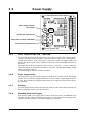
Power Supply ..................................................................................................................................................... 31
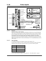
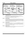
Pulse Inputs ........................................................................................................................................................ 33
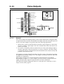
Pulse Outputs ..................................................................................................................................................... 35
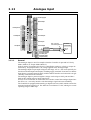
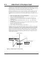
Analogue Input ................................................................................................................................................... 36
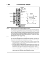
Power Dump Output .......................................................................................................................................... 37
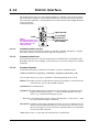
RS232 Interface .................................................................................................................................................. 38
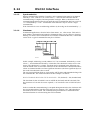
Module Interface ................................................................................................................................................ 41
4
Software .................................................................................................................................... 43
4.1
4.2
4.3
4.4
4.5
4.6
4.7
4.8
4.9
4.10
4.11
4.12
Use of RS232 Commands .................................................................................................................................. 44
Gear Mode (MO=1) ........................................................................................................................................... 45
Positioning Mode (MO=2) ................................................................................................................................. 46
Register Mode (MO=3) ...................................................................................................................................... 47
Velocity Mode (MO=4) ..................................................................................................................................... 50
Torque Mode (MO=5) ....................................................................................................................................... 51
Program Execution in the AMC12 ..................................................................................................................... 52
Mechanical Reset ............................................................................................................................................... 63
Adjustment of Analogue Input ........................................................................................................................... 64
Command Description ....................................................................................................................................... 65
Error Messages ................................................................................................................................................. 113
Alphabetical Overview of Commands ............................................................................................................. 118
5
Appendix ................................................................................................................................. 121
5.1
5.2
5.3
5.4
5.5
5.6
5.7
5.8
5.9
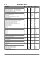
Technical Data ................................................................................................................................................. 122
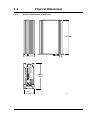
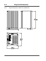
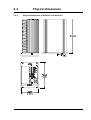
Physical Dimensions ........................................................................................................................................ 123
Servo Loop ....................................................................................................................................................... 126
Error Indication ................................................................................................................................................ 127
Common Errors ................................................................................................................................................ 128
Connection of an unknown motor type ............................................................................................................ 129
Examples of Motor Connection ....................................................................................................................... 141
Typical Applications ........................................................................................................................................ 143
Connector Board .............................................................................................................................................. 144
JVL Industri Elektronik A/S - User Manual - AC servocontroller AMC10/11/12
1
Introduction
JVL Industri Elektronik A/S - User Manual - AC servocontroller AMC10/11/12
1
1.1
Features
15-80VDC
= Extended functions in AMC11 and AMC12
AMC10/12C:
15-80VDC
AMC11B/12B:
230VAC
U=Min.
Filter and
fuse
Power supply
Voltage
monitoring
8
Digital current
regulation
U=Max.
U=Dump
3(2)-phase
MosFet
Driver
4
Brushless
Servo or
Step motor
Current
External
Ballast
Resistor
Power Dump
Transceiver
RS232 Interface
8 Basic inputs
Internal
power
supply
Reset and
temperature
monitoring
Signal processor
Short-circuit
protection
Opto-coupler
Daisy-Chain
Processor
Interface logic
Digital Filter
A/D converter
for digital
current loop
Balanced
input
Analogue output
Motor torque
Encoder input
Hall input
Opto-coupler
Opto-coupler
Pulse inputs /
Encoder input
(electronic gear)
Opto-coupler
Analogue output
(2. axes)
8 Basic outputs
Program Processor
Opto-coupler
2 End-of-travel limit inputs
1 Zero-point seek input
+/- 10V In
Velocity
Torque
Pulse output
Flash PROM
with code
protection
A/D Converter
10-bit + Sign
Opto-coupler
Expansion
Interbus-S module
Field bus
Interbus-S
TT0044GB
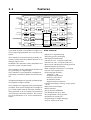
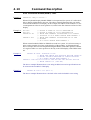
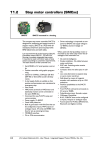
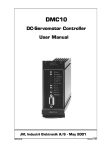
Types AMC10, AMC11 and AMC12 comprise a se- Main Features:
ries of compact programmable AC servo motor controllers.
• Digital servo regulation loop
• Extremely precise positioning
The Controllers are characterised by an ability for • Small physical dimensions
control via either the built-in RS232 interface or an • Current 6A cont., 12A peak (AMCxxB)
analogue input (±10V).
• Current 12A cont., 25A peak (AMCxxC)
In addition, the Controllers can be controlled as in a
• Short-circuit and thermal-overload protection
step motor system via pulse inputs.
• Absolute/Relative positioning
The Controllers can be configured for absolute/rela- • EMC compliant construction - CE marked
• Current overload protection
tive positioning via 6 digital inputs.
• Following input facilities:
The Controllers accept a balanced or unbalanced
Analogue +/-10V
signal from a standard 2-channel incremental encoStep-pulse and direction
der.
Pulse up - pulse down
Incremental encoder
All inputs and outputs are optically isolated and proDigital selection of position
tected against voltage overloads.
• Graphic monitoring of velocity, torque, position, etc.
The Controllers are equipped with 8 general-purpo• End-of-travel limit inputs
se outputs. These can be configured, for example, to
give a ready signal when the motor has reached its • RS232 Interface
desired position, or an error signal if an obstruction • Set-up stored in EEPROM
occurs that prevents motor operation. The Control- • Can handle motors up to 1kW
lers can be mounted in a 19” rack or mounted on a • Pre-programmed velocity profiles
• Automatic zero-point seek
surface.
• Programming via simple language
• Any AC motor can be used
2
JVL Industri Elektronik A/S - User Manual - AC servocontroller AMC10/11/12
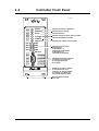
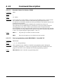
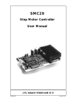
1.2
Controller Front Panel
TT0015GB
Industri Elektronik
IO1
IO2
IO3
IO4
Power
Running
Error
Current
T>80 C
Out Error
IO5
IO6
IO7
IO8
RS232
Indicates Controller is switched on
Indicates motor is running
Indicates fatal error
Indicates average current to motor exceeded
Indicates temperature exceeded
Indicates user output is short-circuited
Indication of levels at user
inputs/outputs
If LED register = 1,
output levels are displayed
If LED register = 0,
input levels are displayed
SUB-D 9 Pole Interface connector.
Connected to PC or terminal
for set up/programming
of Controller
Handle for use when Controller
is removed from 19" rack.
Controller can also be mounted
on a surface in a cabinet, etc.,
using BASE1 mounting plate
Mounting holes for fixture
in 19" rack.
JVL Industri Elektronik A/S - User Manual - AC servocontroller AMC10/11/12
3
1.3
1.3.1
Overview of Operating Modes
Basic Modes of Controller Operation
The AMC series of Servo Controllers includes many individual features for use in a
wide range of applications. The Controllers are operated in one of five basic modes of
operation which are selected using the Mode command MO. The basic modes of operation are as follows:
1. Gear Mode
In Gear Mode, the Controller functions as in a step motor system. The motor will
move one step each time a voltage pulse is applied to the Controller’s pulse inputs.
Velocity and acceleration/deceleration are determined by the externally applied pulse
frequency.
Configuration of these pulse inputs enables the following:
• Connection of an incremental encoder so that the motor operates at a selectable
gearing ratio in relation to the encoder (electronic gearing).
• Connection of a step-pulse and direction signal to the 2 pulse inputs. This represents a typical step motor configuration.
• Connection of a pulse signal to one of the two pulse inputs. If the motor is required
to move forward, pulses are applied to one input; if the motor is required to move
in the opposite direction, pulses are applied to the other input.
2. Positioning Mode
In Positioning Mode, the Controller positions the motor via commands transmitted
over the RS232 interface.
This mode can be used primarily when the Controller is part of a system which is permanently connected to a PC via the RS232 interface. In addition, it is recommended
that Positioning Mode is used during installation and commissioning of systems.
3. Register Mode
In this mode, the Controller’s set of parameter registers (X0-X63) store the position
and velocity values etc. required by the actual system. These registers can be addressed via the User Inputs and are activated by activating a start input. This mode of operation is especially powerful since the Controller itself takes care of the entire
positioning sequence.
4. Velocity Mode
In this mode, the Controller controls the motor velocity via the analogue input.
This mode is typically used for simple applications or applications in which another
device, such as a PC-card or PLC with controller modules, is used for overall control
of velocity and position.
5. Torque Mode
In Torque Mode, the Controller controls the motor torque via the analogue input.
Typical applications for this mode include, for example, spooling or tensioning of
foil, cable etc.
The individual modes of operation are illustrated further in the following pages. These pages provide a quick guide to setting up a functional system. For more detailed documentation of the modes of operation, the individual inputs and outputs and the Controller
command set are described in Hardware, page 19 and Software, page 45.
4
JVL Industri Elektronik A/S - User Manual - AC servocontroller AMC10/11/12
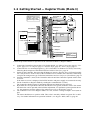
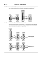
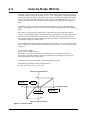
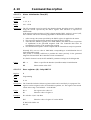
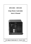
1.4
Getting Started — Gear Mode (Mode 1)
AMC11B/12B does not use
terminals P- and P+ since it
includes a mains supply.
See Power Supply section!
Industry bus in
User Outputs
User Inputs
IA1
IA2
IA3
IA4
O+
O8
O7
O6
O5
O4
O3
O2
O1
OIN8
IN7
IN6
IN5
IN4
IN3
IN2
IN1
IN-
Power Supply in
1C
1A
2C
2A
3C
3A
4C
4A
5C
5A
6C
6A
7C
7A
8C
8A
9C
9A
10C
10A
11C
11A
12C
12A
13C
13A
14C
14A
15C
15A
16C
16A
17C
17A
18C
18A
19C
19A
20C
20A
21C
21A
22C
22A
23C
23A
24C
24A
25C
25A
26C
26A
27C
27A
28C
28A
29C
29A
30C
30A
31C
31A
32C
32A
PP+
FA
FB
FC
FD
PDO
IB1
IB2
IB3
IB4
HLA
HLB
HLC
5VO
EZ1
EZ2
EA1
EA2
EB1
EB2
ECM
XCM
XI
YCM
YI
O5V
AO
BO
OCM
AIN
ACM
26B
27B
28B
30B
31B
32B
NL
PL
HM
AX2
TCM
TAC
+
15-80V DC
Screen
For electronic gearing an
incremental encoder is used
Power Dump output
Industry bus out
Hall Input
Channel A
Ground
Channel B
Screen
PLC or Pulse
Generator
Screen
23A-26A Pulse Inputs
PNP outputs
Pulse Outputs
+/- 10V Input
Pulse output
Ground
Direction output
Note ! : screen only
connected to signal source.
End-of-travel inputs
Home (Reset) input
Secondary axis
Analogue output
(torque monitor)
TT0017GB
Follow the procedure below for operation of the Controller in Mode 1 (Gear Mode)
1. Connect the Controller as shown above. For further details, see: Motor Connection, page 21 / Encoder Input, page 28 / Power Supply, page 31 / Pulse Inputs, page 33.
2. Connect the PC via a terminal program (e.g. JVL’s MotoWare or Windows Terminal), if necessary
following the description of the RS232 interface in RS232 Interface, page 38.
3. Switch on the Controller, but ensure that all inputs are inactive. Only the Power LED and possibly
Out 1 may be active. If one or more of the red LEDs is active or blinks, the Controller is most likely
set up for the wrong motor type. Follow the instructions in General Aspects of Installation, page 12
4. Send the command ? (enter) to the Controller and wait until the Controller responds with a status
overview.
If the status overview is displayed, the RS232 interface and power supply are connected correctly.
5. Set the Controller to Gear Mode by sending the command MO=1 (enter).
The Controller should respond Y, indicating that Gear Mode (Mode 1) has been selected.
6. By default, the servo parameters KD, KP, and KI are set to typical, moderate values. This means
that the motor can be operated without further adjustment. For optimum system operation however, the parameters should be adjusted. See Adjustment of Servo Regulation, page 16.
7. The Controller is now set to Gear Mode.
JVL Industri Elektronik A/S - User Manual - AC servocontroller AMC10/11/12
5
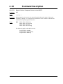
1.5 Getting Started — Positioning Mode (Mode 2)
AMC11B/12B does not use
terminals P- and P+ since it
includes a mains supply.
See Power Supply section!
Industry bus in
User Outputs
User Inputs
IA1
IA2
IA3
IA4
O+
O8
O7
O6
O5
O4
O3
O2
O1
OIN8
IN7
IN6
IN5
IN4
IN3
IN2
IN1
IN-
Power Supply in
1C
1A
2C
2A
3C
3A
4C
4A
5C
5A
6C
6A
7C
7A
8C
8A
9C
9A
10C
10A
11C
11A
12C
12A
13C
13A
14C
14A
15C
15A
16C
16A
17C
17A
18C
18A
19C
19A
20C
20A
21C
21A
22C
22A
23C
23A
24C
24A
25C
25A
26C
26A
27C
27A
28C
28A
29C
29A
30C
30A
31C
31A
32C
32A
PP+
FA
FB
FC
FD
PDO
IB1
IB2
IB3
IB4
HLA
HLB
HLC
5VO
EZ1
EZ2
EA1
EA2
EB1
EB2
ECM
XCM
XI
YCM
YI
O5V
AO
BO
OCM
AIN
ACM
26B
27B
28B
30B
31B
32B
NL
PL
HM
AX2
TCM
TAC
+
15-80V DC
Screen
Power Dump output
Industry bus out
Hall Input
Screen
Pulse Inputs
Pulse Outputs
+/- 10V Input
End-of-travel inputs
Home (Reset) Input
Secondary axis
Analogue output
(torque monitor)
TT0018GB
Follow the procedure below for operation of the Controller in Mode 2 (Positioning Mode)
1. Connect the Controller as shown above. For further details, see: Motor Connection, page 21 / Encoder Input, page 28 / Power Supply, page 31.
2. Connect the PC via a terminal program (e.g. JVL’s MotoWare or Windows Terminal), if necessary
following the description of the RS232 interface in RS232 Interface, page 38.
3. Switch on the Controller, but ensure that all inputs are inactive. Only the Power LED and possibly
Out 1 may be active. If one or more of the red LEDs is active or blinks, the Controller is most likely
set up for the wrong motor type. Follow the instructions in General Aspects of Installation, page 12
4. Send the command ? (enter) to the Controller and wait until the Controller responds with a status
overview.
If the status overview is displayed, the RS232 interface and power supply are connected correctly.
5. Set the Controller to Positioning Mode by sending the command MO=2 (enter).
The Controller should respond Y, indicating that Positioning Mode has been selected.
6. By default, the servo parameters KD, KP, and KI are set to typical, moderate values. This means
that the motor can be operated without further adjustment. For optimum system operation however,
the parameters must be adjusted. See Adjustment of Servo Regulation, page 16.
7. The Controller is now set to Positioning Mode. As a test, the motor can be moved to absolute position 1000 by sending the command SP=1000 (enter). The motor should move to the specified position. By sending the command SP=-1000 (enter), the motor will move in the opposite direction to
position -1000. If this does not occur, or if the motor runs for a very long time, it may be due to the
fact that the position counter either was at position 1000, or that the previous position was far from
1000. See Positioning Mode (MO=2), page 48 and Command Description, page 67 for details of
other commands.
6
JVL Industri Elektronik A/S - User Manual - AC servocontroller AMC10/11/12
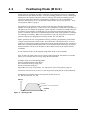
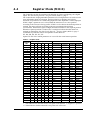
1.6 Getting Started — Register Mode (Mode 3)
AMC11B/12B does not use
terminals P- and P+ since it
includes a mains supply.
See Power Supply section!
Industry bus in
+24VDC Out
PLC or
similar
User Outputs
Position reached
Start
Pause
D5
D4
D3
D2
D1
D0
Ground
User Inputs
IA1
IA2
IA3
IA4
O+
O8
O7
O6
O5
O4
O3
O2
O1
OIN8
IN7
IN6
IN5
IN4
IN3
IN2
IN1
IN-
Power Supply in
1C
1A
2C
2A
3C
3A
4C
4A
5C
5A
6C
6A
7C
7A
8C
8A
9C
9A
10C
10A
11C
11A
12C
12A
13C
13A
14C
14A
15C
15A
16C
16A
17C
17A
18C
18A
19C
19A
20C
20A
21C
21A
22C
22A
23C
23A
24C
24A
25C
25A
26C
26A
27C
27A
28C
28A
29C
29A
30C
30A
31C
31A
32C
32A
PP+
FA
FB
FC
FD
PDO
IB1
IB2
IB3
IB4
HLA
HLB
HLC
5VO
EZ1
EZ2
EA1
EA2
EB1
EB2
ECM
XCM
XI
YCM
YI
O5V
AO
BO
OCM
AIN
ACM
26B
27B
28B
30B
31B
32B
NL
PL
HM
AX2
TCM
TAC
+
15-80V DC
Screen
Power Dump output
Industry bus out
Hall Input
Screen
Pulse Inputs
Pulse Outputs
+/- 10V Input
End-of-travel inputs
Secondary axis
Analogue output
(torque monitor)
From zero-point
sensor
Home (Reset) input
TT0019GB
Follow the procedure below for operation of the Controller in Mode 3 (Register Mode)
1.
2.
3.
4.
5.
6.
7.
Connect the Controller as shown above. For further details, see: Motor Connection, page 21 / User
Inputs, page 24 / User Outputs, page 27 / Encoder Input, page 28 / Power Supply, page 31.
Connect the PC via a terminal program (e.g. JVL’s MotoWare or Windows Terminal), if necessary
following the description of the RS232 interface in RS232 Interface, page 38.
Switch on the Controller, but ensure that all inputs are inactive. Only the Power LED and possibly
Out 1 may be active. If one or more of the red LEDs is active or blinks, the Controller is most likely
set up for the wrong motor type. Follow the instructions in General Aspects of Installation, page 12
Send the command ? (enter) to the Controller and wait until the Controller responds with a status
overview.
If the status overview is displayed, the RS232 interface and power supply are connected correctly.
Set the Controller to Register Mode by sending the command MO=3 (enter).
The Controller should respond Y, indicating that Register Mode has been selected.
By default, the servo parameters KD, KP, and KI are set to typical, moderate values. This means
that the motor can be operated without further adjustment. For optimum system operation however, the parameters must be adjusted. See Adjustment of Servo Regulation, page 16.
The Controller is now set to Register Mode. As a test, connect a voltage to input 1 and 8 (start input).
The motor should move to position 1000. This value is stored by default in register XP1 on delivery. For further information on operation in Mode 3, see Register Mode (MO=3), page 49
JVL Industri Elektronik A/S - User Manual - AC servocontroller AMC10/11/12
7
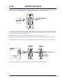
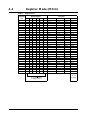
1.7 Getting Started — Velocity Mode (Mode 4)
AMC11 does not use
terminals P- and P+ since it
includes a mains supply.
See Power Supply section!
Industry bus in
User Outputs
User Inputs
IA1
IA2
IA3
IA4
O+
O8
O7
O6
O5
O4
O3
O2
O1
OIN8
IN7
IN6
IN5
IN4
IN3
IN2
IN1
IN-
Power Supply in
1C
1A
2C
2A
3C
3A
4C
4A
5C
5A
6C
6A
7C
7A
8C
8A
9C
9A
10C
10A
11C
11A
12C
12A
13C
13A
14C
14A
15C
15A
16C
16A
17C
17A
18C
18A
19C
19A
20C
20A
21C
21A
22C
22A
23C
23A
24C
24A
25C
25A
26C
26A
27C
27A
28C
28A
29C
29A
30C
30A
31C
31A
32C
32A
PP+
FA
FB
FC
FD
PDO
IB1
IB2
IB3
IB4
HLA
HLB
HLC
5VO
EZ1
EZ2
EA1
EA2
EB1
EB2
ECM
XCM
XI
YCM
YI
O5V
AO
BO
OCM
AIN
ACM
26B
27B
28B
30B
31B
32B
NL
PL
HM
AX2
TCM
TAC
+
15-80V DC
Screen
Power Dump output
Industry bus out
Hall Input
Screen
Pulse Inputs
PC-card or
Potentiometer
Pulse Outputs
+/- 10V Input
Screen
±10V Out
Ground
E
End-of-travel
inputs
Home (Reset) input
Secondary axis
Analogue output
(torque monitor)
Note ! : screen only
connected to signal source.
TT0020GB
Follow the procedure below for operation of the Controller in Mode 4 (Velocity Mode)
1.
2.
3.
4.
5.
6.
7.
8
Connect the Controller as shown above. For further details, see: Motor Connection, page 21 / Encoder Input, page 28 / Power Supply, page 31 / Analogue Input, page 36.
Connect the PC via a terminal program (e.g. JVL’s MotoWare or Windows Terminal), if necessary
following the description of the RS232 interface in RS232 Interface, page 38.
Switch on the Controller, but ensure that the Analogue Input is 0 volt. Only the Power LED and
possibly Out 1 may be active. If one or more of the red LEDs is active or blinks, the Controller is
most likely set up for the wrong motor type. Follow the instructions in General Aspects of Installation, page 12
Send the command ? (enter) to the Controller and wait until the Controller responds with a status
overview.
If the status overview is displayed, the RS232 interface and power supply are connected correctly.
Set the Controller to Velocity Mode by sending the command MO=4 (enter).
The Controller should respond Y, indicating that Velocity Mode has been selected.
By default, the servo parameters KD, KP, and KI are set to typical, moderate values. This means
that the motor normally can be operated without further adjustment. For optimum system operation however, the parameters must be adjusted. If the motor is inoperative, first try setting KI to a
high value (100-1000). See also Adjustment of Servo Regulation, page 16
The Controller is now set to Velocity Mode. When the voltage applied to the analogue input is greater than 0V, the motor will move at a velocity which is proportional to the applied voltage. If the
applied voltage is less than 0V (negative), the motor will move in the opposite direction.
For further information, see Velocity Mode (MO=4), page 52.
JVL Industri Elektronik A/S - User Manual - AC servocontroller AMC10/11/12
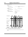
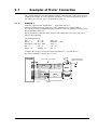
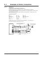
1.8 Getting Started — Torque Mode (Mode 5)
AMC11B/12B does not use
terminals P- and P+ since it
includes a mains supply.
See Power Supply !
Industry bus in
User Outputs
User Inputs
IA1
IA2
IA3
IA4
O+
O8
O7
O6
O5
O4
O3
O2
O1
OIN8
IN7
IN6
IN5
IN4
IN3
IN2
IN1
IN-
Power Supply in
1C
1A
2C
2A
3C
3A
4C
4A
5C
5A
6C
6A
7C
7A
8C
8A
9C
9A
10C
10A
11C
11A
12C
12A
13C
13A
14C
14A
15C
15A
16C
16A
17C
17A
18C
18A
19C
19A
20C
20A
21C
21A
22C
22A
23C
23A
24C
24A
25C
25A
26C
26A
27C
27A
28C
28A
29C
29A
30C
30A
31C
31A
32C
32A
PP+
FA
FB
FC
FD
PDO
IB1
IB2
IB3
IB4
HLA
HLB
HLC
5VO
EZ1
EZ2
EA1
EA2
EB1
EB2
ECM
XCM
XI
YCM
YI
O5V
AO
BO
OCM
AIN
ACM
26B
27B
TT0021GB
28B
30B
31B
32B
NL
PL
HM
AX2
TCM
TAC
+
15-80V DC
Screen
Power Dump output
Industry bus out
Hall Input
Screen
Pulse Inputs
PC-card or
Potentiometer
Pulse Outputs
+/- 10V Input
Screen
±10V Ud
Stel
End-of-travel inputs
Home (Reset) input
Secondary axis
Analogue output
(torque monitor)
Note ! : screen only
connected to signal source.
TT0021GB
Follow the procedure below for operation of the Controller in Mode 5 (Torque Mode)
1.
2.
3.
4.
5.
6.
7.
Connect the Controller as shown above. For further details, see also: Motor Connection, page 21
/ Power Supply, page 31 / Analogue Input, page 36.
Connect the PC via a terminal program (e.g. JVL’s MotoWare or Windows Terminal), if necessary
following the description of the RS232 interface in RS232 Interface, page 38.
Switch on the Controller, but ensure that the Analogue Input is 0 volt. Only the Power LED and
possibly Out 1 may be active. If one or more of the red LEDs is active or blinks, the Controller is
most likely set up for the wrong motor type. Follow the instructions in General Aspects of Installation, page 12
Send the command ? (enter) to the Controller and wait until the Controller responds with a status
overview.
If the status overview is displayed, the RS232 interface and power supply are connected correctly.
Set the Controller to Torque Mode by sending the command MO=5 (enter).
The Controller should respond Y, indicating that Torque Mode has been selected.
By default, the servo parameters KD, KP, and KI are set to typical, moderate values. This means
that the motor can be operated without further adjustment. For optimum system operation however, the parameters must be adjusted. If the motor is inoperative, first try setting KI to a high value
(100-1000). See also Adjustment of Servo Regulation, page 16.
The Controller is now set to Torque Mode. When the voltage applied to the Analogue Input is greater than 0V, the motor will produce a positive torque which is proportional to the applied voltage.
When the input voltage is less than 0V (negative), the motor will produce a negative torque proportional to the applied voltage.
For further information, see Torque Mode (MO=5), page 53.
JVL Industri Elektronik A/S - User Manual - AC servocontroller AMC10/11/12
9
10
JVL Industri Elektronik A/S - User Manual - AC servocontroller AMC10/11/12
2
Installation and Adjustment
JVL Industri Elektronik A/S - User Manual - AC servocontroller AMC10/11/12
11
2.1
General Aspects of Installation
It is recommended that this section is read carefully in conjunction with the installation
of the AC Servo Controller.
When the Controller has been installed, the following check-list should be followed:
1. Ensure that the selection of the Controller’s basic mode of operation (1-5) is correct.
If necessary refer to Overview of Operating Modes, page 4 which explains the overall
use of the various modes of operation.
2. Connect the motor, encoder, any hall-sensor, diverse end-of-travel inputs, inputs and
outputs as required. Details of motor connection, inputs and inputs, powering, etc. are
given in Hardware, page 19.
Note: Connection of motors, encoders, etc.: The Appendix (Examples of Motor Connection, page 143) gives specific connection diagrams for a number of AC servo motors and step motors. These sections also give the associated parameter values that the
Controller should be set to for optimum motor operation.
3. Connect the power to the Controller. Most probably the default parameter settings
will not correspond to the actual motor connected.
This will result in the Controller reporting an error and current to the motor will be
disconnected.
If the actual motor used is one of the types named in the Appendix (Examples of Motor Connection, page 143) or included in Motoware’s parameter list, these parameter
values must be transferred to the Controller. See Transfer of Parameters to the Controller, page 13.
If the motor is recognised, the system should function optimally after transfer of the
associated parameter set. Some fine adjustment may be carried out as described in
this chapter. The basic installation of the Controller is now complete and the specific
function of the Controller can now be set up and tested. See the description of Modes
1 to 5 in the Software section, pages 47 to 53 depending on the required mode of operation.
To optimise the complete system, follow the instructions given in Adjustment of Servo Regulation, page 16.
If the motor is not recognised, follow the instructions given in Connection of an unknown motor type, page 131.
12
JVL Industri Elektronik A/S - User Manual - AC servocontroller AMC10/11/12
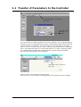
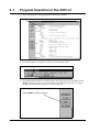
2.2 Transfer of Parameters to the Controller
”Controller Spec." selected in
this menu.
Key “OK” when
"AMC1xx" is
selected
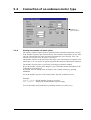
For easy transfer of complete parameter sets to the Controller, JVL’s programming tool
MotoWare can be recommended. The program is started and the RS232 cable connected
to the Controller. Set MotoWare to work with the AC-servo controller by selecting
AMC1xx (AC-Servo) in the Controller Spec. window in the Setup menu. See illustration
above. This adjusts MotoWare to work with the AMC10, 11 and 12, making available
new windows with, amongst others, graphic display of motor running conditions.
Key OK and the following screen is displayed.
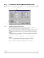
"Parameter Sets" selected in
this menu
TT0048-DK
Select Parameter Sets in the Applications menu.
This gives access to the window containing all the basic parameters in the Controller.
JVL Industri Elektronik A/S - User Manual - AC servocontroller AMC10/11/12
13
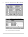
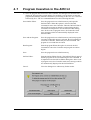
2.2
Transfer of Parameters to the Controller
Select "File" to obtain the motor list
To select a specific motor type, select File. The following window will appear.
Select "Open" to obtain the motor parameters
Select motor type
Select the required motor type and select Open to view the parameters.
14
JVL Industri Elektronik A/S - User Manual - AC servocontroller AMC10/11/12
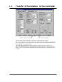
2.2
Transfer of Parameters to the Controller
Send set-up to the Controller
Save set-up in memory
The parameters will now appear on the screen in the parameter window.
These are the default values, which can then be adjusted as required. When all parameters
are set as required, they can be sent to the Controller via this screen. Select Send to transfer the parameters to the Controller.
The Controller will probably prompt to initiate a restart. In this case, answer Yes.
Then select EEPROM to store the parameters permanently in the Controller. The Controller is now set up for the selected motor. Restart the Controller by switching off and
on again.
JVL Industri Elektronik A/S - User Manual - AC servocontroller AMC10/11/12
15
2.3
2.3.1
Adjustment of Servo Regulation
Adjustment of Servo Parameters
The AMC Controller servo regulator is of the PID-type and has therefore 3 parameters
that must be adjusted.
The function of the servo loop is to ensure that the motor operates smoothly with stable
movements and stops at its intended location. The 3 servo parameters must be adjusted
according to the actual conditions of the specific system, since the motor type, load, supply voltage and other factors all have a decisive influence on the required value of the
parameters.
The 3 servo parameters are denoted as follows and have the following functions:
KP Determines the system’s proportional amplification. This parameter is the most important of the 3 since the system will function using this parameter alone.
KD Determines the system’s differential amplification. This parameter determines how
aggressively the system reacts to sudden changes in load or a sudden change in velocity.
KI Determines the integration of positional error. This parameter determines the extent
to which a persistent positional error influences the motor’s position and velocity.
The 3 parameters can be quickly adjusted in the following manner:
Start Motoware and open the On-line editor. Parameter values can be keyed in directly
from the editor.
1. Set all 3 parameters to 0 by keying KP=0 (enter), followed by KI=0 (enter), followed
by KD=0 (enter).
2. The value of KP is then slowly increased until the system begins to become unstable.
KP is then adjusted to half this value.
3. To make the system response quicker, KD can be adjusted.
The value of KD is increased until the system becomes unstable. KD is then adjusted
to 0.5 to 0.7 of this value.
4. The value of KI is then increased until the system is unstable. KI is then set to approximately 0.5 to 0.75 of this value.
5. If the system is required to react quickly to a positioning error, but the summed error
is not allowed to increase indefinitely, the integral summation limit IL should be
used.
6. Adjustment of the servo parameters can be completed by fine tuning the individual
parameters.
7. Remember to store the parameter values in permanent memory by keying MS (enter).
16
JVL Industri Elektronik A/S - User Manual - AC servocontroller AMC10/11/12
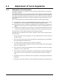
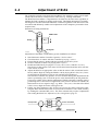
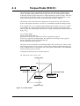
2.4
Adjustment of BIAS
The Controller includes a parameter denoted BIAS. This parameter can be used in applications where the motor is subjected to a static load, e.g. a lifting mechanism.
The BIAS function enables a compensation to be made for the static load, regardless of
whether the load is pushing or pulling on the motor. This BIAS adjustment is normally
advantageous since the load on the PID filter is uniform regardless of the direction of motor rotation and ultimately enables easier adjustment of the complete system and a faster
response time.
Illustration of lifting mechanism:
Motor
Static load
Drive
Kg
90 Degrees
TT0040GB
Adjustment of the BIAS is made during system installation as follows:
1.
2.
3.
4.
5.
Start Motoware and the Controller. Open the “On line editor”.
Check that there is contact with the Controller by keying ? (enter).
Ensure that the motor is loaded with the required load for the system.
Set the Controller to Mode 2 by keying MO=2 (enter).
Disable the PID filter by keying KP=0 (enter) KI=0 (enter) and KD=0 (enter).
Note however that current to the motor will be disconnected and the motor will therefore release its load.
6. Adjust the BIAS to an appropriate value so that the motor is able to hold the load relatively stable. Begin by setting the BIAS to 100 by keying BIAS=100 (enter). Increase the BIAS in increments of 100 or less until the load is balanced.
Note that the Controller may produce an error condition during this adjustment if the
motor’s positioning error exceeds the preset value determined by the PE parameter.
If necessary, adjust PE to 0 during adjustment of BIAS so that the Controller ignores
positioning error. If the load is in opposition to the positive direction of rotation, the
BIAS must be set in a negative range, e.g. BIAS= -100 (enter). Note that if the BIAS
value is set too high, the motor will begin to run.
7. Finally, the filter parameters (KP, KI, KD) are reset to the values used before adjusting the BIAS and the BIAS value is stored in the Controller’s non-volatile memory
by sending the command MS (enter). The filter constants may require re-adjustment
after setting the BIAS. See Adjustment of Servo Regulation, page 16
Desired velocity
KP
Desired position
+
KI
KD
KVFF
+
+
+
+
+
BIAS
TT0041GB
To motor commutation
Actual position
JVL Industri Elektronik A/S - User Manual - AC servocontroller AMC10/11/12
17
18
JVL Industri Elektronik A/S - User Manual - AC servocontroller AMC10/11/12
3
Hardware
JVL Industri Elektronik A/S - User Manual - AC servocontroller AMC10/11/12
19
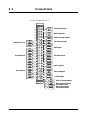
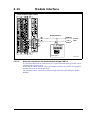
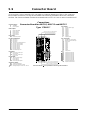
3.1
Connections
(Connector DIN41612 ver. C)
Industry bus in
User Outputs
User Inputs
IA1
IA2
IA3
IA4
O+
O8
O7
O6
O5
O4
O3
O2
O1
OIN8
IN7
IN6
IN5
IN4
IN3
IN2
IN1
IN-
1C
1A
2C
2A
3C
3A
4C
4A
5C
5A
6C
6A
7C
7A
8C
8A
9C
9A
10A
10C
11C
11A
12C
12A
13C
13A
14C
14A
15C
15A
16C
16A
17C
17A
18C
18A
19C
19A
20C
20A
21C
21A
22C
22A
23C
23A
24C
24A
25C
25A
26C
26A
27C
27A
28C
28A
29C
29A
30C
30A
31C
31A
32C
32A
PP+
FA
FB
FC
FD
PDO
IB1
IB2
IB3
IB4
HLA
HLB
HLC
5VO
EZ1
EZ2
EA1
EA2
EB1
EB2
ECM
XCM
XI
YCM
YI
O5V
AO
BO
OCM
AIN
ACM
26B
27B
TT0026GB
28B
30B
31B
32B
20
NL
PL
HM
AX2
TCM
TAC
Power Supply in
Motor Output
Power Dump output
Industry bus out
Hall Input
Encoder Input
Pulse Inputs
Pulse Outputs
+/- 10V Input
End-of-travel inputs
Home (Reset) input
Secondary axis
Analogue output
(torque monitor)
JVL Industri Elektronik A/S - User Manual - AC servocontroller AMC10/11/12
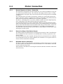
3.2
Motor Connection
3.2.1
General Aspects of Motor Connection
The Controller is designed for use with common AC servo motors (brushless) or step motors with an incremental encoder. The Controller can supply currents of up to 12 Amp
continuous and 25 Amp peak. These current values must be set using software commands
CA and CP.
The Controller Driver uses Mos-Fet transistors, which give exceptionally good performance. The motor voltage is regulated at a frequency of 24.3kHz, which ensures that the
motor does not produce any audible noise as a result of regulation.
The Driver’s switching time is very short (<200nS), which can result in high-frequency
noise components in the cables between the Driver and the motor.
In certain situations this can result in undesirable influences on other electronic equipment in close proximity to the servo motor system. To avoid this problem, the connection
between the Controller and the motor should be made using screened cable, as shown in
the illustrations on pages 22 and 23. Furthermore, it is strongly recommended that
screened cable is also used for the encoder cable to avoid influences from the motor cable
affecting the encoder signal.
3.2.2
Short-circuiting of the Motor Output
The Motor Output can withstand short-circuiting between the FA, FB, FC and FD terminals. In addition, all motor terminals can withstand short-circuiting to ground or to the
positive supply.
If a short circuit occurs, the Controller will stop all activity and report an error condition
by activating the red Current LED. In addition, the Controller’s error register will be activated. See the ES and EST commands.
3.2.3
Allowable Motor Inductance
The Driver can drive motors that have an inductance per phase in the range 0.5 to 20 mH.
If a motor with a lower inductance is used, an inductance of 0.5-1mH must be connected
in series with each motor lead.
This inductance will function as an integrator and ensure that the Controller controls the
current correctly.
JVL Industri Elektronik A/S - User Manual - AC servocontroller AMC10/11/12
21
3.2
Motor Connection
Industry bus in
User Outputs
User Inputs
IA1
IA2
IA3
IA4
O+
O8
O7
O6
O5
O4
O3
O2
O1
OIN8
IN7
IN6
IN5
IN4
IN3
IN2
IN1
IN-
1C
1A
2C
2A
3C
3A
4C
4A
5C
5A
6C
6A
7C
7A
8C
8A
9C
9A
10C
10A
11C
11A
12C
12A
13C
13A
14C
14A
15C
15A
16C
16A
17C
17A
18C
18A
19C
19A
20A
20C
21C
21A
22C
22A
23C
23A
24C
24A
25C
25A
26C
26A
27A
27C
28C
28A
29C
29A
30C
30A
31C
31A
32C
32A
PP+
FA
FB
FC
FD
PDO
IB1
IB2
IB3
IB4
HLA
HLB
HLC
5VO
EZ1
EZ2
EA1
EA2
EB1
EB2
ECM
XCM
XI
YCM
YI
O5V
AO
BO
OCM
AIN
ACM
26B
27B
TT0022GB
28B
30B
31B
32B
3.2.4
NL
PL
HM
AX2
TCM
TAC
Power Supply in
Screen
"FD" is not used for AC servo motors
Power Dump output
Industry bus out
W
V
U
Hall Input
Encoder Input
AC Servo Motor
Pulse Inputs
Pulse Outputs
+/- 10V Input
End-of-travel inputs
Home (Reset) input
Secondary axis
Analogue output
(torque monitor)
Connection of 3-phase Motor
To connect a 3-phase brushless motor to the Controller, terminals FA, FB and FC are
used.
Screened cable must be used to connect the motor to the Controller.
The specific motor’s average current and peak current must be set using the 2 Controller
commands CA and CP. See Adjustment of Motor Current, page 137.
See Examples of Motor Connection, page 143 for connection of various types of motor.
22
JVL Industri Elektronik A/S - User Manual - AC servocontroller AMC10/11/12
3.2
Motor Connection
Industry bus in
User Outputs
User Inputs
IA1
IA2
IA3
IA4
O+
O8
O7
O6
O5
O4
O3
O2
O1
OIN8
IN7
IN6
IN5
IN4
IN3
IN2
IN1
IN-
1C
1A
2C
2A
3C
3A
4C
4A
5C
5A
6C
6A
7C
7A
8C
8A
9C
9A
10C
10A
11C
11A
12C
12A
13C
13A
14C
14A
15C
15A
16A
16C
17C
17A
18C
18A
19C
19A
20C
20A
21C
21A
22C
22A
23C
23A
24A
24C
25C
25A
26C
26A
27C
27A
28A
28C
29C
29A
30C
30A
31C
31A
32C
32A
PP+
FA
FB
FC
FD
PDO
IB1
IB2
IB3
IB4
HLA
HLB
HLC
5VO
EZ1
EZ2
EA1
EA2
EB1
EB2
ECM
XCM
XI
YCM
YI
O5V
AO
BO
OCM
AIN
ACM
26B
27B
TT0023GB
28B
30B
31B
32B
3.2.5
NL
PL
HM
AX2
TCM
TAC
Power Supply in
Screen
Power Dump out
Industry bus out
Hall Input
Step Motor
Encoder Input
Pulse Inputs
Pulse Outputs
+/- 10V Input
End-of-travel inputs
Home (Reset) input
Secondary axis
Analogue output
(torque monitor)
Connection of 2 or 4-phase Step Motors
To connect a 2 or 4-phase step motor to the Controller, terminals FA, FB, FC and FD are
used.
Screened cable must be used to connect the motor to the Controller.
The specific motor’s average current and peak current must be set using the 2 Controller
commands CA and CP. See Adjustment of Motor Current, page 137.
When a standard step motor with a resolution of 200 steps per revolution is used, the encoder used must have a minimum resolution of 4000 pulses per revolution. Similarly it is
recommended that the encoder has an index pulse. See also Encoder Input, page 28
See Examples of Motor Connection, page 143 for connection of various types of motor.
JVL Industri Elektronik A/S - User Manual - AC servocontroller AMC10/11/12
23
3.3
User Inputs
(Connector DIN41612 ver. C)
This diagram is used if an NPN output is connected
Power Supply
+5-30VDC
+
Inductive
sensor
or similar
R
1C
1A
2C
2A
3C
3A
4C
4A
5A
5C
NPN Output
Industry bus in
PNP Output
User Outputs
+
Power Supply
+5-30VDC
Inductive
sensor
or similar
User Inputs
IA1
IA2
IA3
IA4
O+
O8
O7
O6
O5
O4
O3
O2
O1
OIN8
IN7
IN6
IN5
IN4
IN3
IN2
IN1
IN-
6C
6A
7C
7A
8C
8A
9C
9A
10C
10A
11C
11A
12C
12A
13C
13A
14C
14A
15C
15A
16C
16A
17C
17A
18C
18A
19C
19A
20C
20A
21C
21A
22C
22A
23C
23A
24A
24C
25C
25A
26C
26A
27C
27A
28C
28A
29C
29A
30C
30A
31C
31A
32C
32A
PP+
FA
FB
FC
FD
PDO
IB1
IB2
IB3
IB4
HLA
HLB
HLC
5VO
EZ1
EZ2
EA1
EA2
EB1
EB2
ECM
XCM
XI
YCM
YI
O5V
AO
BO
OCM
AIN
ACM
26B
27B
TT0024GB
28B
30B
31B
32B
NL
PL
HM
AX2
TCM
TAC
Power Supply in
Motor Output
Power Dump output
Industry bus out
Hall Input
Encoder Input
Pulse Inputs
Pulse Outputs
+/- 10V Input
End-of-travel inputs
Home (Reset) input
Secondary axis
Analogue output
(torque monitor)
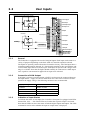
3.3.1
General
The Controller is equipped with a total of 8 digital inputs. Each input can be used for a
variety of purposes depending on the basic mode of Controller operation selected.
The Inputs are optically isolated from other Controller circuitry. All of the Inputs have a
common ground terminal, denoted IN-. Note that this terminal is also used with the endof-travel limit input and reset (Home) input. Each Input can operate with voltages in the
range 5 to 30VDC. Note that the Inputs should normally be connected to a PNP output
since a positive current must be applied for an input to be activated.
3.3.2
Connection of NPN Output
If an Input is connect to an NPN output, a Pull-Up resistor must be connected between
the Input and the + supply. See above illustration. The value of the resistance used depends on the supply voltage. The following resistances are recommended:
3.3.3
24
Supply Voltage
Recommended Resistance
5-12VDC
1kOhm / 0.25W
12-18VDC
2.2kOhm / 0.25W
18-24VDC
3.3kOhm / 0.25W
24-30VDC
4.7kOhm / 0.25W
Indication of Input Status
To indicate the status of each Input, the Controller’s front panel is equipped with LEDs
denoted IO1, IO2,..... IO8. These LEDs are lit when the respective Input is activated.
Note that the LEDs can show the status of both the digital inputs and outputs. The LED
command is used to select whether the input or output status is displayed.
JVL Industri Elektronik A/S - User Manual - AC servocontroller AMC10/11/12
3.4
End-of-travel Limit Inputs
(Connector DIN41612 ver. C)
This diagram is followed if an NPN output is used
1C
Industry bus in
User Outputs
User Inputs
IA1
IA2
IA3
IA4
O+
O8
O7
O6
O5
O4
O3
O2
O1
OIN8
IN7
IN6
IN5
IN4
IN3
IN2
IN1
IN-
1A
2C
2A
3C
3A
4C
4A
5C
5A
6C
6A
7C
7A
8C
8A
9C
9A
10C
10A
11C
11A
12C
12A
13C
13A
14C
14A
15C
15A
16C
16A
17C
17A
18C
18A
19C
19A
20C
20A
21C
21A
22C
22A
23C
23A
24C
24A
25C
25A
26C
26A
27C
27A
28C
28A
29C
29A
30C
30A
31C
31A
32C
32A
PP+
FA
FB
FC
FD
PDO
IB1
IB2
IB3
IB4
HLA
HLB
HLC
5VO
EZ1
EZ2
EA1
EA2
EB1
EB2
ECM
XCM
XI
YCM
YI
O5V
AO
BO
OCM
AIN
ACM
26B
27B
Note that End-of-travel inputs,
IN1-8 and HM input share a
common ground (IN-)
28B
30B
31B
32B
NL
PL
HM
AX2
TCM
TAC
Power Supply in
R
Inductive
sensor
or similar
Motor Output
Power Dump Output
+
Power Supply
+5-30VDC
Industry bus out
NPN Output
Hall Input
Encoder Input
Pulse Inputs
PNP Output
Pulse Outputs
+/- 10V Input
+
End-of-travel Inputs
Home (Reset)Input
Secondary axis
Analogue Output
(torque monitor)
Inductive
sensor
or similar
Power Supply
+5-30VDC
TT0012GB
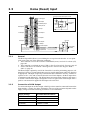
3.4.1
General
The Controller is equipped with end-of-travel limit inputs denoted NL (negative limit)
and PL (positive limit). The Inputs are optically isolated from other Controller circuitry
with the exceptions of IN1 - IN8, and HM (Home input). All of these inputs have a common ground denoted IN-. The End-of-travel Limit Inputs operate with voltages in the range 5 to 30VDC. Note that the Inputs must normally receive a signal from a PNP output
since a positive current must be applied for the Inputs to be activated.
Activation of the PL Input will halt motor operation if the motor is moving in a positive
direction. The motor can however operate in a negative direction even if the PL Input is
activated.
Activation of the NL Input will halt motor operation if the motor is moving in a negative
direction. The motor can however operate in a positive direction even if the NL Input is
activated.
An error message will be set in the Controller’s error register if either the NL or PL Inputs
has been activated. See Error Messages, page 115
3.4.2
Connection of NPN Output
To connect an end-of-travel input to an NPN output, a Pull-Up resistor must be connected
between the Input and the + supply. See above illustration.
The size of the resistance depends on the supply voltage used. The following resistances
are recommended:
Supply Voltage
Recommended Resistance
5-12VDC
1kOhm / 0.25W
12-18VDC
2.2kOhm / 0.25W
18-24VDC
3.3kOhm / 0.25W
24-30VDC
4.7kOhm / 0.25W
JVL Industri Elektronik A/S - User Manual - AC servocontroller AMC10/11/12
25
3.5
Home (Reset) Input
(Connector DIN41612 ver. C)
This diagram is used if an NPN output is connected
Industry bus in
User Outputs
User Inputs
IA1
IA2
IA3
IA4
O+
O8
O7
O6
O5
O4
O3
O2
O1
OIN8
IN7
IN6
IN5
IN4
IN3
IN2
IN1
IN-
1C
1A
2C
2A
3C
3A
4C
4A
5C
5A
6C
6A
7C
7A
8C
8A
9C
9A
10C
10A
11C
11A
12C
12A
13C
13A
14C
14A
15C
15A
16C
16A
17C
17A
18C
18A
19C
19A
20C
20A
21C
21A
22C
22A
23C
23A
24C
24A
25C
25A
26C
26A
27C
27A
28C
28A
29C
29A
30C
30A
31C
31A
32C
32A
PP+
FA
FB
FC
FD
PDO
IB1
IB2
IB3
IB4
HLA
HLB
HLC
5VO
EZ1
EZ2
EA1
EA2
EB1
EB2
ECM
XCM
XI
YCM
YI
O5V
AO
BO
OCM
AIN
ACM
26B
27B
Note that End-of-travel inputs,
IN1-8 and HM input share a
common ground (IN-)
28B
30B
31B
32B
NL
PL
HM
AX2
TCM
TAC
Power Supply in
Motor Output
R
Inductive
sensor
or similar
Power Dump output
+
Power Supply
+5-30VDC
Industry bus out
NPN Output
Hall input
Encoder Input
Pulse Inputs
PNP Output
Pulse Outputs
+/- 10V Input
+
End-of-travel inputs
Secondary axis
Analogue output
(torque monitor)
Home (Reset)Input
Inductive
sensor
or similar
Power Supply
+5-30VDC
TT0013GB
3.5.1
General
The Reset Input HM (Home) is used during the zero-point seek function. A zero-point
seek occurs after one of the following conditions:
1. The Controller receives the seek zero command SZ (reset). See Seek Zero Point (SZ),
page 108
2. The Controller is switched on (only if XR=1). See Zero Point Seek Function, page 65
3. If the Controller is set to Mode 3 and register 0 is selected. See Register Mode
(MO=3), page 49
The Home Input is primarily used if the Controller is used for positioning purposes, although in Velocity or Torque Mode there may be special applications where the function
is appropriate. The Input is optically isolated from other Controller circuitry, with the exceptions of IN1 - IN8, and NL and PL (End-of-travel Limit Inputs). All these inputs have
a common ground denoted IN-. The Home Input can operate with voltages in the range 5
to 30VDC. Note that the Input is designed to receive a signal from a PNP output since a
positive current must be applied for the Input to be activated.
3.5.2
Connection of NPN Output
To connect the Input to an NPN output, a Pull-Up resistor must be connected between the
Input and the + supply. See above illustration. The size of the resistance depends on the
supply voltage used. The following resistances are recommended:
26
Supply Voltage
Recommended Resistance
5-12VDC
1kOhm / 0.25W
12-18VDC
2.2kOhm / 0.25W
18-24VDC
3.3kOhm / 0.25W
24-30VDC
4.7kOhm / 0.25W
JVL Industri Elektronik A/S - User Manual - AC servocontroller AMC10/11/12
3.6
User Outputs
(Connector DIN41612 ver. C)
AMCxx output circuit (PNP output)
O+
O8
O7
O6
O5
O4
O3
O2
O1
O-
14C
15C
1C
1A
16C
2C
2A
17C
3C
3A
18C
4C
4A
19C
5C
5A
20C
6C
6A
7C
7A
21C
22C
AMCxx
23C
Industry bus in
User Outputs
+
Power Supply
5-30VDC
Max. 250mA
Load
User Inputs
IA1
IA2
IA3
IA4
O+
O8
O7
O6
O5
O4
O3
O2
O1
OIN8
IN7
IN6
IN5
IN4
IN3
IN2
IN1
IN-
8C
8A
9C
9A
10C
10A
11C
11A
12A
12C
13C
13A
14C
14A
15C
15A
16C
16A
17A
17C
18C
18A
19C
19A
20C
20A
21C
21A
22A
22C
23C
23A
24C
24A
25C
25A
26C
26A
27C
27A
28A
28C
29C
29A
30C
30A
31C
31A
32C
32A
PP+
FA
FB
FC
FD
PDO
IB1
IB2
IB3
IB4
HLA
HLB
HLC
5VO
EZ1
EZ2
EA1
EA2
EB1
EB2
ECM
XCM
XI
YCM
YI
O5V
AO
BO
OCM
AIN
ACM
26B
27B
TT0025GB
28B
30B
31B
32B
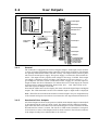
3.6.1
NL
PL
HM
AX2
TCM
TAC
Power Supply in
Motor Output
Power Dump output
Industry bus out
Hall Input
Encoder Input
Pulse Inputs
Pulse Outputs
+/- 10V Input
End-of-travel inputs
Home (Reset) input
Secondary axis
Analogue output
(torque monitor)
General
The Controller is equipped with a total of 8 digital outputs. Each output can be used for
a variety of purposes depending on the Controller’s basic mode of operation. The Outputs
are optically isolated from other Controller circuitry. The output circuitry must be powered from an external power supply. This power supply is connected to the terminals O+
and O-. The output circuitry operates with voltages in the range 5-30VDC. Each output
can supply a continuous current of 250mA. The Outputs are all source drivers, i.e. if a
given Output is activated, contact is made between the +supply (O+) and the respective
output terminal. See above illustration. To indicate the level of each output, the Controller front panel is equipped with LEDs, denoted IO1, IO2,..... IO8. These LEDs are lit
when the respective Output is activated.
Note that the LEDs can be used to display the status of both the digital inputs and digital
outputs. The LED command is used to select whether input or output status is displayed.
Note ! The LEDs do not indicate the actual level at the Outputs. They are coupled directly
to the internal microprocessor and are not connected to the output terminals themselves.
3.6.2
Overload of User Outputs
All of the Outputs are short-circuit protected, which means that the output is automatically disconnected in the event of a short circuit. The Output will first function normally
again when the short-circuit has been removed and the power to the Controller has been
disconnected for at least 5 seconds. The Out Error LED on the Controller’s front panel
is lit when one or more of the Outputs has been short-circuited. The LED also indicates
if the output circuitry has overheated due to an overload.
JVL Industri Elektronik A/S - User Manual - AC servocontroller AMC10/11/12
27
3.7
Encoder Input
(Connector DIN41612 ver. C)
Industry bus in
User Outputs
User Inputs
IA1
IA2
IA3
IA4
O+
O8
O7
O6
O5
O4
O3
O2
O1
OIN8
IN7
IN6
IN5
IN4
IN3
IN2
IN1
IN-
1C
1A
2C
2A
3C
3A
4C
4A
5C
5A
6C
6A
7C
7A
8C
8A
9C
9A
10C
10A
11C
11A
12C
12A
13C
13A
14C
14A
15C
15A
16C
16A
17C
17A
18C
18A
19C
19A
20C
20A
21C
21A
22C
22A
23A
23C
24C
24A
25C
25A
26C
26A
27C
27A
28C
28A
29C
29A
30C
30A
31C
31A
32C
32A
PP+
FA
FB
FC
FD
PDO
IB1
IB2
IB3
IB4
HLA
HLB
HLC
5VO
EZ1
EZ2
EA1
EA2
EB1
EB2
ECM
XCM
XI
YCM
YI
O5V
AO
BO
OCM
AIN
ACM
26B
27B
TT0027GB
Connection of balanced encoder
28B
30B
31B
32B
NL
PL
HM
AX2
TCM
TAC
Power Supply in
Motor Output
Power Dump output
Industry bus out
Incrementalencoder
Hall Input
15A-22AEncoder Interface
5VDC
Z
Z
A
A
B
B
GND
Pulse Inputs
Motor
It is recommended that
screened cable is used to the
encoder.
Pulse Outputs
+/- 10V Input
End-of-travel inputs
Home (Reset)input
Secondary axis
Analogue output
(torque monitor)
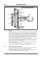
3.7.1
General
An incremental encoder must be used together with the Controller regardless of whether
the Controller is used with an AC servo motor or a step motor. It is recommended that an
encoder with an index channel is used, i.e. that in addition to the A and B channels, the
encoder has a third channel which produces 1 impulse for each motor revolution. This
pulse is used to reset the Controller’s commutation circuitry and ensures that a missing
pulse on either the A or B channel is compensated for. Without an index channel, over a
long period of operation the Controller will produce an error due to incorrect commutation of the motor. Alternatively the system efficiency can be reduced.
The incremental encoder detects the motor’s velocity and position. Almost all types of
encoder can be used providing they are equipped with one of the following types of output: NPN, PNP-, Push-Pull-, or Balanced output.
The Encoder Input can read an encoder signal up to 500kHz. The encoder signal voltage
must be in the range 0 to 5V.
Note ! — The Cable between the encoder and the Controller must be screened and the
screen must only be connected to the encoder chassis terminal (ECM).
For details of general encoder set-up, see Set-up of Encoder Resolution, page 132.
3.7.2
Encoders with Balanced Output
To connect an encoder with a balanced output to the Controller, see the above illustration.
Note that the use of an encoder with balanced outputs is recommended.
It is recommended that 0.3mm2 (minimum) screened cable is used.
The encoder should under no circumstances share a cable with other signal cables as this
can have serious and catastrophic effect on encoder signals.
28
JVL Industri Elektronik A/S - User Manual - AC servocontroller AMC10/11/12
3.7
Encoder Input
(Connector DIN41612 ver. C)
Industry bus in
User Outputs
User Inputs
IA1
IA2
IA3
IA4
O+
O8
O7
O6
O5
O4
O3
O2
O1
OIN8
IN7
IN6
IN5
IN4
IN3
IN2
IN1
IN-
1C
1A
2C
2A
3C
3A
4C
4A
5C
5A
6C
6A
7C
7A
8C
8A
9C
9A
10C
10A
11C
11A
12C
12A
13C
13A
14C
14A
15C
15A
16C
16A
17C
17A
18C
18A
19C
19A
20C
20A
21C
21A
22C
22A
23C
23A
24C
24A
25C
25A
26C
26A
27A
27C
28C
28A
29C
29A
30C
30A
31C
31A
32C
32A
PP+
FA
FB
FC
FD
PDO
IB1
IB2
IB3
IB4
HLA
HLB
HLC
5VO
EZ1
EZ2
EA1
EA2
EB1
EB2
ECM
XCM
XI
YCM
YI
O5V
AO
BO
OCM
AIN
ACM
26B
27B
TT0028GB
28B
30B
31B
32B
NL
PL
HM
AX2
TCM
TAC
Connection of unbalanced encoder
Power Supply in
Motor Output
Power Dump output
Industry bus out
Incrementalencoder
Hall Input
15A-22AEncoder Interface
5VDC
Z
A
Motor
B
GND
Pulse Inputs
It is recommended that
screened cable is used to the
encoder.
Pulse Outputs
+/- 10V Input
End-of-travel inputs
Home (Reset)input
Secondary axis
Analogue output
(torque monitor)
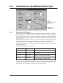
3.7.3
Encoders with Unbalanced Output
As mentioned above, the Controller can be used with almost all types of encoder, including encoders with unbalanced outputs.
Some types of encoder have an NPN or a PNP output. For these types, the Controller ET
command is used to configure the Encoder Input for the specific encoder.
If encoders with balanced/unbalanced outputs of the type push-pull or source/sink are
used, this configuration can be omitted.
3.7.4
Special Encoders/Sensors
JVL currently plans to supply other adaptor modules for other types of encoder and sensor. Contact JVL Industri Elektronik for further details.
It is recommended that screened, twisted-pair (0.3mm2 minimum) cable is used.
The encoder should under no circumstances share a cable with other signal cables as this
can have serious and catastrophic effect on encoder signals.
JVL Industri Elektronik A/S - User Manual - AC servocontroller AMC10/11/12
29
3.8
Hall Input
(Connector DIN41612 ver. C)
1C
Industry bus in
User Outputs
User Inputs
IA1
IA2
IA3
IA4
O+
O8
O7
O6
O5
O4
O3
O2
O1
OIN8
IN7
IN6
IN5
IN4
IN3
IN2
IN1
IN-
1A
2C
2A
3C
3A
4C
4A
5C
5A
6C
6A
7C
7A
8C
8A
9C
9A
10C
10A
11C
11A
12C
12A
13C
13A
14C
14A
15C
15A
16C
16A
17C
17A
18C
18A
19C
19A
20C
20A
21C
21A
22C
22A
23C
23A
24C
24A
25C
25A
26C
26A
27A
27C
28C
28A
29C
29A
30C
30A
31C
31A
32C
32A
PP+
FA
FB
FC
FD
PDO
IB1
IB2
IB3
IB4
HLA
HLB
HLC
5VO
EZ1
EZ2
EA1
EA2
EB1
EB2
ECM
XCM
XI
YCM
YI
O5V
AO
BO
OCM
AIN
ACM
26B
27B
TT0029GB
28B
30B
31B
32B
3.8.1
30
NL
PL
HM
AX2
TCM
TAC
Power Supply in
Motor Output
Power Dump output
Industry bus out
Hall Unit
Hall Inputs
15A-22AEncoder Interface
5VDC
HALL A
HALL B
Motor
HALL C
GND
Pulse Inputs
It is recommended that
screened cable is used to
hall-units.
Pulse Outputs
+/- 10V Input
End-of-travel inputs
Home (Reset)input
Secondary axis
Analogue output
(torque monitor)
General
The Controller is equipped with 3 inputs for connection of a Hall sensor. This feature is
only used if it is required that the motor does not move during start up of the Controller.
The Hall Input can only be used with 3-phase motors and not with step motors.
Almost all types of Hall sensor can be connected, providing they are equipped with one
of the following types of output: NPN-, PNP-, or Push-Pull output.
The Hall sensor signals must be within the voltage range 0 to 5V.
Note ! — The cable between the Hall sensor and the Controller must always be screened
cable and the screen must only be connected to the Controller’s encoder/hall chassis terminal (ECM).
For further details, see Setting the Hall Element, page 139.
JVL Industri Elektronik A/S - User Manual - AC servocontroller AMC10/11/12
3.9
Power Supply
Power Supply in
+
Industry bus in
User Outputs
User Inputs
IA1
IA2
IA3
IA4
O+
O8
O7
O6
O5
O4
O3
O2
O1
OIN8
IN7
IN6
IN5
IN4
IN3
IN2
IN1
IN-
1C
1A
2C
2A
3C
3A
4C
4A
5C
5A
6C
6A
7C
7A
8C
8A
9C
9A
10C
10A
11C
11A
12C
12A
13C
13A
14C
14A
15C
15A
16C
16A
17A
17C
18C
18A
19C
19A
20C
20A
21C
21A
22C
22A
23C
23A
24A
24C
25C
25A
26C
26A
27C
27A
28A
28C
29C
29A
30C
30A
31C
31A
32C
32A
PP+
FA
FB
FC
FD
PDO
IB1
IB2
IB3
IB4
HLA
HLB
HLC
5VO
EZ1
EZ2
EA1
EA2
EB1
EB2
ECM
XCM
XI
YCM
YI
O5V
AO
BO
OCM
AIN
ACM
26B
27B
TT0030GB
28B
30B
31B
32B
NL
PL
HM
AX2
TCM
TAC
15-80V DC
Motor Output
Power Dump output
Industry bus out
Hall Input
Encoder Input
Pulse Inputs
Pulse Outputs
+/- 10V Input
End-of-travel inputs
Home (Reset) input
Secondary axis
Analogue output
(torque monitor)
3.9.1
General Aspects of Power Supply
Powering of the Controller is relatively simple. Types AMC10B, AMC10C and
AMC12C require a supply voltage in the range 15-80VDC. Type AMC11B/12B is equipped with a built-in mains supply and must therefore be connected to 230VAC — see description on page 32.
3.9.2
Power Supply of AMC10B, AMC10C and AMC12C
To ensure that powering of the Controller is as simple as possible, only a single supply
voltage is connected. Internal supply circuitry ensures the correct supply voltages for the
Driver, control circuits, etc. For optimum driver performance, it is recommended that a
capacitance of minimum 2000-5000µF is connected to the supply. Similarly, it is recommended that 1.5mm cable (minimum) is used to connect the power supply to the
Controller. If the driver supply voltage falls below 12V, the internal reset circuitry will
reset the driver. Provision should therefore be made to ensure that the supply voltage is
always maintained at a minimum of 12-15V, even in the event of a mains voltage drop.
3.9.3
Earthing
To ensure proper chassis-earth connection, the chassis, mains earth connector and P- (minus) are internally connected in the Controller.
3.9.4
Power Supply Faults
The Controller is protected against incorrect polarity connection and voltage overload.
If a voltage overload of the Controller supply occurs, or the supply is connected with incorrect polarity, the Controller’s internal fuse will be blown. The fuse can only be replaced by an authorised service centre. Note that AMC 11 has an external fuse — see
description on page 32.
JVL Industri Elektronik A/S - User Manual - AC servocontroller AMC10/11/12
31
3.9
Power Supply
JVL Industri Elektronik A/S - Made In Denmark
1C 1B 1A
Industri Elektronik
Mains Voltage Selection
115 / 230VAC
032
115
Mains
Voltage
Selector
Primary Fuse slow-blow 2A
Serial Number
Mains Power Connector 115/230VAC
Secondary Fuse slow-blow 4A
32C 32B 32A
Fuses
Mains Input
TT0031GB
3.9.5
Power Supply of AMC11B / AMC12B
To ensure that powering of the Controller is as simple as possible, only a single supply
voltage is connected to the Controller. The built-in power supply ensures the required
voltages for the Driver, control circuitry, etc. The power supply can supply 160W (continuous) but allows a peak load of 300W in connection with acceleration/deceleration of
the motor.
The Controller can be powered from either 115VAC or 230VAC (+/-10%). Connection
of the mains supply is made at the Controller’s rear panel, where the mains supply voltage
setting can also be adjusted.
The internal supply voltage is 80VDC (nominal).
3.9.6
Power Supply Faults
The Controller is protected against voltage overload. In the event of overload, the internal
circuitry short-circuits the supply and thus blows the secondary, and possibly the primary, fuse. The Controller is equipped with a mains noise suppression filter which removes
any transients.
3.9.7
Earthing
To ensure proper chassis-earth connection, the chassis, mains earth connector and P- (minus) are internally connected in the Controller.
3.9.8
Extending the Power Supply
If the built-in 160W power supply does not have sufficient capacity, an additional external supply can be connected as illustrated on page 31. Note that the external supply must
operate at the same voltage as the internal supply (80V nominal).
32
JVL Industri Elektronik A/S - User Manual - AC servocontroller AMC10/11/12
3.10
Pulse Inputs
This diagram is used if a PNP output is connected
(Connector DIN41612 ver. C)
PNP Output
Industry bus in
User Outputs
User Inputs
IA1
IA2
IA3
IA4
O+
O8
O7
O6
O5
O4
O3
O2
O1
OIN8
IN7
IN6
IN5
IN4
IN3
IN2
IN1
IN-
1C
1A
2C
2A
3C
3A
4C
4A
5C
5A
6C
6A
7C
7A
8C
8A
9C
9A
10C
10A
11C
11A
12C
12A
13C
13A
14C
14A
15C
15A
16C
16A
17C
17A
18C
18A
19C
19A
20C
20A
21C
21A
22C
22A
23A
23C
24C
24A
25C
25A
26C
26A
27A
27C
28C
28A
29C
29A
30C
30A
31C
31A
32C
32A
PP+
FA
FB
FC
FD
PDO
IB1
IB2
IB3
IB4
HLA
HLB
HLC
5VO
EZ1
EZ2
EA1
EA2
EB1
EB2
ECM
XCM
XI
YCM
YI
O5V
AO
BO
OCM
AIN
ACM
26B
27B
TT0032GB
28B
30B
31B
32B
NL
PL
HM
AX2
TCM
TAC
+
Power Supply in
5-30VDC
Pulse
source
To XI
or YI
R
To XCM
or YCM
Motor Output
Power Dump output
This diagram is used if an NPN output is connected
To XI
or YI
Industry bus out
+
Hall Input
Pulse
source
R
NPN Output
To XCM
or YCM
Encoder Input
PLC or Pulse
Generator
Pulse Inputs
Pulse output
Ground
Direction output
Screen
PNP outputs
Pulse Outputs
+/- 10V Input
End-of-travel inputs
Home (Reset) input
Secondary axis
Analogue output
(torque monitor)
Note ! : screen only
connected to signal source.
Channel A
Ground
Channel B
For electronic gearing an
incremental encoder is used
3.10.1
General
The Pulse Inputs are used in Mode 1.
Each time a voltage pulse is applied to the Inputs, the motor moves a specified amount.
This amount is determined by the GEAR command and the encoder resolution. Both Inputs are equipped with a built-in noise filter which cuts off all frequencies above 1MHz.
The diagram on the following page illustrates minimum durations for the signals.
Note that if the source used for the pulse and/or direction signal has a PNP output, the
Inputs must be connected as shown for PNP above. Similarly if the signal source is of the
NPN type, the Inputs must be connected for NPN above. It is recommended that screened
cable is used.
3.10.2
Input Voltage
As standard, the Inputs are designed to operate with voltages of 5V.
If greater input voltages are used, a resistor R must be connected as shown in the above
illustration. The value of the required resistance is given in the following table.
Voltage
Resistance
5-8V
0 Ohm (short-circuited)
8-12V
470 Ohm / 0.25W
12-18V
1.2 kOhm / 0.25W
18-24V
1.8 kOhm / 0.25W
24-30V
2.2 kOhm / 0.25W
See also the description of Mode 1 Getting Started — Gear Mode (Mode 1), page 5.
JVL Industri Elektronik A/S - User Manual - AC servocontroller AMC10/11/12
33
3.10
Pulse Inputs
Input Configuration 1
Input Configuration 2
Input Configuration 3
Inputs "XI" and "YI" are supplied with
signals from an incremental encoder.
Normally used for "electronic gearing"
Input "XI" is supplied with pulses
and input "YI" determines the direction.
Movement occurs on the rising flanks.
Function and minimum durations :
Function and minimum durations :
Pulses applied to input "XI" move the motor
in a positive direction. Pulses applied to
"YI" move the motor in a negative direction.
Movement occurs on the rising flanks.
Function and minimum durations :
2.0µs
1.0µs
1.0µs
2.0µs
1.0µs
2.0µs
XI
(Pulse)
XI
(A)
XI
(Pulse+)
2µs
90 degrees
2µs
1.0µs
1.0µs
YI
(B)
YI
(Direction)
+Direction
+Direction
+Direction
Motor
Motor
Motor
-Direction
-Direction
-Direction
2µs
1.0µs
YI
(Pulse-)
TT0033GB
3.10.3
Pulse Input Format
The Pulse Inputs can be set to 3 different configurations. See above illustration.
These configurations are selected using the PIF command. See Pulse Input Format
(PIF), page 95. The 3 configurations have the following function.
For further details, see Gear Mode (MO=1), page 47.
3.10.4
Input Format 1
This format is normally used if the Controller is used in a system as an electronic gear.
An incremental encoder is connected to the input to read the motor movement. The GEAR
command is set to select the required gear ratio and the PIF command is used to set Input
Format 1 (PIF=1). The input circuitry will then decode the incoming pulses according to
the above illustration. See also the PRM command.
3.10.5
Input Format 2
This format is normally used if the system receives pulses from a PLC or PC controller
module. The Controller functions as in a step motor system and the motor will move a
specified amount each time a pulse is applied to the XI input. The voltage level at YI determines the direction of motor movement.
3.10.6
Input Format 3
This format corresponds to Format 2, but the direction of motor movement is determined
by which input (XI or YI) pulses are applied to.
34
JVL Industri Elektronik A/S - User Manual - AC servocontroller AMC10/11/12
3.11
Pulse Outputs
(Connector DIN41612 ver. C)
1C
1A
2C
2A
3C
3A
4C
4A
5A
5C
Industry bus in
IA1
IA2
IA3
IA4
6C
6A
7C
7A
8C
8A
9C
9A
10C
10A
11C
11A
12C
12A
13A
13C
User Outputs
User Inputs
O+
O8
O7
O6
O5
O4
O3
O2
O1
OIN8
IN7
IN6
IN5
IN4
IN3
IN2
IN1
IN-
14C
14A
15C
15A
16C
16A
17C
17A
18C
18A
19C
19A
20C
20A
21C
21A
22C
22A
23C
23A
24C
24A
25C
25A
26C
26A
27C
27A
28C
28A
29C
29A
30A
30C
31C
31A
32C
32A
PP+
FA
FB
FC
FD
PDO
IB1
IB2
IB3
IB4
HLA
HLB
HLC
5VO
EZ1
EZ2
EA1
EA2
EB1
EB2
ECM
XCM
XI
YCM
YI
O5V
AO
BO
OCM
AIN
ACM
26B
27B
TT0014GB
28B
30B
31B
32B
3.11.1
AMCxx Pulse Outputs (NPN outputs)
NL
PL
HM
AX2
TCM
TAC
27A
Power Supply in
Motor output
O5V
28A
AO
29A
BO
30A
OCM
Power Dump output
AMCxx
Industry bus out
Hall input
Encoder Input
Load
Pulse Inputs
+
Pulse Outputs
+/- 10V Input
Power Supply
5 VDC +/- 10%
Max. 10mA per output
End-of-travel inputs
Home (Reset) Input
Secondary axis
Analogue output
(torque monitor)
General
The 2 Pulse Outputs AO and BO produce 2 pulse signals which can be configured either
to represent the motor encoder (EA and EB) or the signal connected to the pulse input (XI
and YI). The Pulse Outputs are typically used in the following applications:
1. Master/slave system in which the master-controller’s pulse outputs are connected to
the slave controller’s pulse inputs. The slave controller thus follows the master controller’s movement.
2. PC-system. A Controller which is connected to a PC-card via the analogue input or
the pulse input and exclusively functions as a velocity controller. The Pulse Output
is connected to the PC-card and ensures that information on the current velocity and
position is sent to the PC-card.
The Outputs are optically isolated from other Controller circuitry. The output circuit must
be supplied by an external voltage of 5V. This supply is connected to the O5V and OCM
terminals (see illustration).
Each output can supply up to 10mA and operates with frequencies up to 500kHz.
Both Outputs are NPN, i.e. if a given output is activated, contact is made between the supply (OCM) and the respective output terminal. See above illustration.
Note that Pulse Output configuration must be set using the POF command; see Pulse
Output Format (POF), page 97.
JVL Industri Elektronik A/S - User Manual - AC servocontroller AMC10/11/12
35
3.12
Analogue Input
1C
Industry bus in
User Outputs
User Inputs
IA1
IA2
IA3
IA4
O+
O8
O7
O6
O5
O4
O3
O2
O1
OIN8
IN7
IN6
IN5
IN4
IN3
IN2
IN1
IN-
1A
2C
2A
3C
3A
4C
4A
5C
5A
6C
6A
7C
7A
8C
8A
9C
9A
10C
10A
11C
11A
12C
12A
13C
13A
14C
14A
15C
15A
16C
16A
17C
17A
18C
18A
19C
19A
20C
20A
21C
21A
22C
22A
23C
23A
24C
24A
25C
25A
26C
26A
27C
27A
28C
28A
29C
29A
30C
30A
31C
31A
32C
32A
PP+
FA
FB
FC
FD
PDO
IB1
IB2
IB3
IB4
HLA
HLB
HLC
5VO
EZ1
EZ2
EA1
EA2
EB1
EB2
ECM
XCM
XI
YCM
YI
O5V
AO
BO
OCM
AIN
ACM
26B
27B
TT0034GB
28B
30B
31B
32B
3.12.1
36
NL
PL
HM
AX2
TCM
TAC
Power Supply in
Motor Output
Hall Input
Encoder Input
Pulse Inputs
Pulse Outputs
+/- 10V Input
Note ! : screen only
connected to signal source.
Screen
PC-card or
Potentiometer
±10V out
Ground
End-of-travel inputs
Home (Reset) input
Secondary axis
Analogue output
(torque monitor)
General
The Analogue Input is used for example when the Controller is operated in Velocity
Mode (Mode 4) or Torque Mode (Mode 5).
In these modes of operation, the motor is controlled to produce a velocity or torque determined by, and proportional to, the voltage applied to the Analogue Input.
The Analogue Input accepts input voltages in the range -10V to +10V and is optically isolated from all other inputs and outputs, including supply terminals. Note however that the
Input shares a common internal supply with the RS232 interface and is therefore not galvanically isolated from the interface.
The Analogue Input is protected against voltage overload up to 100V peak and has a
built-in filter which removes input signal noise.
Always use screened cable to connect the source used to control the Analogue Input since
the motor, etc., can easily interfere with the analogue signal and cause instability.
The Controller is equipped with an analog-to-digital converter (ADC) which converts the
measured analogue signal level. The ADC has a resolution of 11 bit, which gives a total
operating range of 2048 steps.
JVL Industri Elektronik A/S - User Manual - AC servocontroller AMC10/11/12
3.13
Power Dump Output
(Connector DIN41612 ver. C)
Power Supply in
+
Industry bus in
User Outputs
User Inputs
IA1
IA2
IA3
IA4
O+
O8
O7
O6
O5
O4
O3
O2
O1
OIN8
IN7
IN6
IN5
IN4
IN3
IN2
IN1
IN-
1C
1A
2C
2A
3C
3A
4C
4A
5C
5A
6C
6A
7C
7A
8C
8A
9C
9A
10C
10A
11C
11A
12C
12A
13C
13A
14C
14A
15C
15A
16C
16A
17C
17A
18C
18A
19C
19A
20C
20A
21C
21A
22C
22A
23C
23A
24C
24A
25C
25A
26C
26A
27C
27A
28C
28A
29C
29A
30C
30A
31C
31A
32C
32A
PP+
FA
FB
FC
FD
PDO
IB1
IB2
IB3
IB4
HLA
HLB
HLC
5VO
EZ1
EZ2
EA1
EA2
EB1
EB2
ECM
XCM
XI
YCM
YI
O5V
AO
BO
OCM
AIN
ACM
26B
27B
TT0035GB
28B
30B
31B
32B
NL
PL
HM
AX2
TCM
TAC
15-80V DC
R
(Min. 15 Ohm)
Power Dump output
Industry bus out
PDO (V)
Hall Input
PDO activated
when voltage
exceeds 89V
Time
Encoder Input
Voltage (V)
Energy fed back from
the motor to the Controller
89V
Nom. 80V
Time
Pulse Inputs
Velocity
Pulse Outputs
+/- 10V Input
Time
End-of-travel inputs
Home (Reset) input
Secondary axis
Analogue output
(torque monitor)
3.13.1
General Aspects of the “Power Dump” Output
If the Controller is used in systems in which there are very large inertial loads (flywheels,
etc.), a problem can arise during deceleration with energy being sent back from the motor
to the Controller supply. This can result in increases in the supply voltage to a critically
high level, above the Controller’s maximum working range. To alleviate this problem,
the “Power Dump” Output (PDO) can be used. This output can be used to sink the energy
to an external shunt resistor and thus avoid that the Controller shuts down and reports an
error. Note that reduction of the velocity VM, acceleration AC, or peak current CP can
minimise the energy surge from the motor.
3.13.2
Detailed Description of “Power Dump”
The value of the PDO shunt resistor will depend on many parameters, such as the max.
rpm of the motor, the supply voltage, how rapidly the motor decelerates, etc. It is however
recommended that the resistor has a minimum value of 15 Ohm / 50W. The rated power
of the resistor can be greater or less depending on the actual load.
1. When the Controller registers that the supply voltage exceeds 89V, the PDO output
is activated and the Error LED is lit. The Controller automatically transmits an error
message E29: Supply Voltage exceeds 89 V.
2. If activation of the PDO output and thus the PD shunt resistor does not stop the increase in supply voltage, the following occurs: When the supply voltage exceeds 95V,
the Controller shuts down completely and the motor is short-circuited (and thus stops
instantaneously). The Controller sends an error message E24: Supply Voltage exceeds 95 V. The PDO output is activated until the voltage falls below 89V, and the
Controller remains in this error state until it receives the RESET command — see Reset Controller (RESET), page 104. If the supply voltage continues to increase due to
other circumstances, the Controller’s internal voltage overload circuitry will be activated and short-circuit the supply so that the internal fuse is blown.
JVL Industri Elektronik A/S - User Manual - AC servocontroller AMC10/11/12
37
3.14
3.14.1
RS232 Interface
Interface Connection
The Controller Interface uses the widespread RS232C standard, offering the advantage
that all Personal Computers and standard terminals can be connected via the interface.
The 3 interface signals Rx, Tx and ground are used. The interface cable length should not
exceed 10 metres.
Controller Interface:
Tx-PD
Notice !
The TX-PD terminal must
be connected to Tx (pin 3)
if the controller is not
using adressing
7
5
Signal ground
3
Tx (Transmit)
Rx (Receive)
Chassis ground
(not isolated)
2
1
TT0016GB
3.14.2
Communication Protocol
The Controller uses the following format: (1 startbit), 7 databit, Odd parity, 1 Stop bit
Note that a startbit is always used in the RS232C/V24 protocol.
3.14.3
Communication Rate
The Controller operates at a fixed communication rate (Baud rate) of 9600 Baud. The
Baud Rate must be set accordingly on the terminal or PC used to communicate with the
Controller.
3.14.4
Command Syntax
Communication with the Controller must follow a specific command syntax:
[Address] Command [=Argument] [; Command [=Argument]] [Checksum] <CR>
Text in square brackets [] may be included or omitted depending on the set-up.
Address:This address must be used when more than one Controller is connected to the
same interface. See also the ADDR command.
Command:The command itself.
Argument:The subsequent numeric argument for the command. An argument always
begins with the equal-to sign “=“. Certain commands do not use arguments. (e.g. commands that display set-ups).
;
More than 1 command can be used in a single command line. A semi-colon “;” must
be used to delimit multiple commands.
Checksum:In situations where long communication lines are used, a checksum can be
used to ensure that the commands are received correctly. If an error occurs,
the error message E9 is received and the command must be re-transmitted.
See also the CHS command.
<CR>:ASCII value 13. This character terminates the command line.
38
JVL Industri Elektronik A/S - User Manual - AC servocontroller AMC10/11/12
3.14
RS232 Interface
3.14.5
Synchronisation
During communication with the Controller, each command string must be terminated
either by a <CR> (ASCII 13) or a semi-colon “;”. This tells the Controller that the
command string is complete and interpretation can begin. When a checksum is used,
command interpretation will not begin until the entire command line has been received,
i.e. is terminated by a <CR>. A maximum of 80 characters may be sent in a single
command line.
If the Controller is set to use addressing (ADDR>0), the string can be terminated by "; ;"
3.14.6
Checksum
In industrial applications, electrical noise from motors, etc., often occurs. This noise is
quite arbitrary and random and cannot be eliminated 100% even by effective electrical
filtering. To ensure correct transmission of Controller commands therefore, a checksum
can be used. A typical command line may be as follows:
2 5 K P = 2 5; KI = 4 7 1 d
Address
Command no. 1
Delimiter
Command no. 2
TT0037GB
Checksum
In this example, addressing is used (address 25). Two commands, delimited by a semicolon “;”, are transmitted followed by a checksum. The checksum consists of two characters. The checksum is a ‘simple’ checksum and is calculated in the following way:
First the ASCII value of each of the characters in the command line is determined. These
values are summed and the two least significant characters (the least significant byte) of
the result’s hexadecimal value are used.
The two least significant digits are converted to ASCII values and transmitted along with
the command line. The actual calculation in this example is as follow:
50+53+75+80+61+50+53+59+75+73+61+52+55 = 797 (decimal) = 31d (hexadecimal)
The checksum is thus 1d which is sent as ASCII 49 (decimal) and 100 (decimal). The
hex.characters a-f can also be sent as capitals, i.e. d can also be sent as ASCII 68 (decimal).
In the event that the command string is corrupted during transmission, the checksum will
not correspond and the Controller will report an error message “E9”, indicating that a
checksum error has occurred. The command string must then be re-transmitted. The
checksum function is activated using the CHS command.
JVL Industri Elektronik A/S - User Manual - AC servocontroller AMC10/11/12
39
3.14
3.14.7
RS232 Interface
Connection to PC
For communication from a PC, the following connection diagrams can be used. These
show the connections between the Controller and an IBM AT or IBM-XT/PS2:
PC-XT/PS2
PC-AT
Controller
Controller
8
7
5
3
7
Gnd
Tx
6
Gnd
5
4
Tx
7
2
1
Rx
Rx
Gnd
5
3
3
2
2
1
1
Rx
Gnd
5
Tx
7
Tx
Rx
3
2
1
TT0038GB
3.14.8
Connection of Several Controllers to a PC
For connection of more than 1 Controller to a PC (i.e. using addressing), the connection
diagrams given below can be used. Note that Tx (pin 3) must be connected to TX-PD (pin
7) on one of the Controllers included in the system. The diagrams show the connections
between Controllers and an IBM AT or IBM-XT/PS2:
PC-XT/PS2
Controller
Address 2
Controller
Address 1
Gnd
Gnd
Gnd
To other Controllers
Addresses 3, 4, 5, ....
Controller
Address 1
PC-AT
Gnd
Gnd
Controller
Address 2
Gnd
To other Controllers
Addresses 3, 4, 5, ....
TT0036GB
40
JVL Industri Elektronik A/S - User Manual - AC servocontroller AMC10/11/12
3.15
RS485 Interface
The controller include RS485 beside the normal RS232 interface. The RS485 interface is intended for
purposes where 1 to 32 controllers are connected at the same line in a noisy environment.
B/Terminator
5
9
Signal ground
A/+
4
8
Connect to A if
Controller is the last
Unit on the line
TT0059GB
The communication protocol is exatly the same as RS232. The only difference is the balanced signallines, end the fact that all communication is half duplex wich means that the controller can not send and
receive at the same time as by use of RS232.
The RS485 interface makes it possible to connect up to 32 units at the same lines.
At the last controller the terminal called Terminator (pin 8) must be shorted to the A terminal (pin 4).
Following illustration shows a typical system with 2 or more units connected to a computer or similar.
Controller
Address 1
Controller
Address 2
Master
GND
B/A/+
5
5
9
9
8
4
To controller 3....32
4
Terminator
Computer, PLC
or similar
Connect to A if
Controller is the last
Unit on the line
TT0060GB
The RS485 feature is available at controllers with serial numbers higher than 5500.
JVL Industri Elektronik A/S - User Manual - AC servocontroller AMC10/11/12
41
3.16
Module Interface
Controller AMC12B/C
Connections :
DIN41612
Connector
CON13
15Pin SUB-D
Pin 9C
Pin 10B
Pin 1
Pin 10
Module Interface
A
B
Controller Adress 0
B A
- B A + O HT
KDM10 Adress 1
A
B
To other
Units
B A
- B A + O HT
KDM10 Adress 2
(Term. switch ON)
TT0058GB
3.16.1
Module Interface
The Controller can be connected to different external modules such as keyboard/displaymodule or input/output modules etc.
Connection to external modules is made via the controllers serial module interface using
the two terminals marked A and B. All external module functions are controlled via this
interface. Up to 31 modules (and at least 1 motor controller) can be connected to the interface bus. The module interface offers several advantages in that the interface operates
with a balanced output and has low impedance. In addition, the Controllers module interface is optically isolated from other Controller circuitry.
The module interface is protected against transients on the cable connecting the Controller to external modules. These factors enable communication at long distances despite the
presence of electrical noise. It is recommended that twisted cable is used for connection
between the Controller and other modules on the interface.
If the communication distance between 2 units in a system exceeds 25 metres, the DIP
switch marked TERM must be set to the ON on those units which are located more than
25 metres apart.
See the User Manual for the module in question for details of DIP switch settings.
3.16.2
Adressering af moduler
I communication systems where several modules are connected together, each unit must
be assigned a unique address in the range 1 to 31. The above illustration shows how addresses in a typical system are set.
Note that care must be taken to ensure no two modules use the same address. If the module addresses are not unique, the Controller will terminate program execution and an error message will occur. Note that the Controller’s address is the same as that used for
RS232 communication -Se section Connection of Several Controllers to a PC, page 40.
The address of each module should be set in accordance with the instructions given in the
respective module’s User Manual.
42
JVL Industri Elektronik A/S - User Manual - AC servocontroller AMC10/11/12
3.16
Module Interface
Connectorboard type CON13
Module Interface
IA1
IA2
IA3
IA4
PTAC
O5V
AO
1
2
3
4
5
6
7
8
9
10
11
12
13
14
15
IB1
IB2
IB3
IB4
OCM
BO
A
A
To other
B
B
units
B A
- B A + O HT
KDM10 Adress 1
3.16.3
TT0057GB
External connection via connectorboard type CON13
If external modules must be connected by use of the connectorboard type CON13 the illustration above must be used.
Notice that the other terminals at the 15 pin SUB-D connector are used to other purposes
and therefore must be left unconnected.
The illustration above shows the connection/setup with the keyboard/display module
KDM10.
JVL Industri Elektronik A/S - User Manual - AC servocontroller AMC10/11/12
43
44
JVL Industri Elektronik A/S - User Manual - AC servocontroller AMC10/11/12
4
Software
JVL Industri Elektronik A/S - User Manual - AC servocontroller AMC10/11/12
45
4.1
Use of RS232 Commands
The AMC Controller can be controlled via its RS232 interface. Controller commands are
sent as ASCII characters terminated by <CR> ASCII 13 (decimal) or “;”. See also RS232
Interface, page 38.
Some of the Controller commands have associated command parameters, others do not.
For those commands which use parameters, transmitting the command alone, without
specifying the parameter, will provoke the Controller to respond with the command and
the currently set value of the parameter. If no addressing is used, the Controller always
responds when a command has been received. If the purpose of the command is to display
a value or set-up, the required information will be sent as a reply, or a ‘Y’ will be
transmitted to indicate that the command has been received. In the event that incorrect
information has been sent to the Controller, for example a command that does not exist
or a value that is out of range, the Controller will respond with an error message. Error
messages consist of an ‘E’ followed by a number, followed by an explanatory text. See
Error Messages, page 115.
Example:Sent to Controller
Received from Controller
VM<CR>
VM=500<CR>
Sent to Controller
Received from Controller
VM=600<CR>
Y<CR>
Sent to Controller
Received from Controller
VM=-5<CR>
E2: Out of range<CR>
When addressing is used, the Controller will not acknowledge receipt of a command. Any
errors in communication will be stored in the error status register 0. This register can be
read using the command EST0 (enter) - see also Error Status Text (EST), page 78
Commands may be sent as both upper-case and lower-case characters. With the exception
of error messages, replies from the Controller are always upper-case.
The following sections described all of the RS232 commands. As mentioned above, all
commands must be terminated by a carriage-return character <CR> or a semi-colon “;”
before they will be interpreted by the Controller. These characters are not included in the
description of the individual commands.
46
JVL Industri Elektronik A/S - User Manual - AC servocontroller AMC10/11/12
4.2
Gear Mode (MO=1)
This mode is primarily intended for use as an electronic gear. The Pulse Input XI and YI
are connected to an incremental encoder and the motor will then follow this encoder.
The system can also be controlled as a step motor system via step-pulse and direction
signals. The motor will move one step each time a voltage pulse is applied to the pulse
input. This feature means that in many applications the Controller can replace a classic
step motor system without encoder. The velocity and acceleration/deceleration are
determined by the externally applied voltage pulses.
MO is set to 1 for operation of the AMC Controller in Gear Mode. See also Getting Started — Gear Mode (Mode 1), page 5.
Example of the use of Gear Mode:
Adjust the servo loop (if necessary, see Adjustment of Servo Regulation, page 16) and any
other parameters required.
Select Gear Mode, MO=1
Select the input format using the PIF command. See Pulse Input Format (PIF), page 95
The motor can now be controlled via the Pulse Inputs XI and YI.
Commands of particular interest for operation in this mode are:
PIF, POF, ET, PR, PE
JVL Industri Elektronik A/S - User Manual - AC servocontroller AMC10/11/12
47
4.3
Positioning Mode (MO=2)
In this mode of operation, the AMC Controller will position the motor via commands
transmitted over the RS232 interface. Various operating parameters can be continuously
adjusted via the interface while the motor is running. This mode is primarily used in
systems in which the Controller is permanently connected to a PC via the RS232
interface. MO must be set to 2 for operation in this mode. See Getting Started — Positioning Mode (Mode 2), page 6.
The position is specified in terms of pulses. Note that the Controller multiplies the
number of encoder pulses by a factor of 4. If for example the encoder has a resolution of
500 pulses per revolution, the complete system will have a resolution of 2000 pulses per
revolution. If an operation of 2000 pulses is specified, this means that the motor will
rotate 1 revolution. The motor’s instantaneous position can be read regardless of whether
it is running or stationary. When a new position is set up, the motor moves to the new
position using the pre-programmed velocity profile. See AC and VM.
Motor operation can use a programmed velocity profile by programming a maximum
velocity and acceleration. In this mode, when the motor is operated to move to a new
position, it will operate using the programmed velocity profile and the profile will always
follow the acceleration/deceleration values. This means that the motor may not always
attain maximum velocity if the distance is short. Motor status can be read us the RS
command.
At any time the motor can be stopped using either the H or SH command.
Note: In order to achieve the correct velocity and acceleration, the number of encoder
pulses per revolution must be set up using the PR command.
Example of the use of Positioning Mode:
Select Positioning Mode using MO=2
Set a maximum velocity using VM
Set an acceleration using AC
Adjust the servo loop. If necessary, see Adjustment of Servo Regulation, page 16
The motor can now be set to move to various positions using the SP or SR commands.
Commands of particular interest for operation in this mode are:
ET, PR, SP, SR, VM, AC, PE
Velocity
VM (RPM)
2
3
AC (RPM/S ) and JERK (RPM/S )
Position
TT0001-GB
Figure -1 - Velocity profile
48
JVL Industri Elektronik A/S - User Manual - AC servocontroller AMC10/11/12
4.4
Register Mode (MO=3)
The Controller can also be configured for absolute or relative positioning via 8 digital
inputs. See also Getting Started — Register Mode (Mode 3), page 7.
The Controller has 64 programmable parameter sets. Each parameter set can be used to
store information about acceleration, position (relative or absolute) and velocity.
Selection of a parameter set is made using inputs IN1-IN6. Input IN8 is a start/stop input.
If IN8 is high, a parameter set is selected and the motor moves to a new position
according to the selected velocity profile. If IN8 is set low before the desired position is
reached, the motor will stop according to the pre-programmed deceleration
(acceleration). When IN8 is again set high, the motor continues to the required position.
When the required position is reached, O1 is set high to indicate that the motor has
reached its destination. See also Getting Started — Register Mode (Mode 3), page 7.
Commands of particular interest for operation in this mode are:
ET, PR, XR, XA, XP, XV, PE
Inputs IN1-IN6 select which parameter set is used for the actual motor operation.
Table -1 - Register Sets
Digital Inputs
Register
set
IN6 IN5 IN4 IN3 IN2 IN1 Acceleration
0
1
2
3
4
5
6
7
8
9
10
11
12
13
14
15
16
17
18
19
20
21
22
23
24
25
26
27
28
29
30
31
32
0
0
0
0
0
0
0
0
0
0
0
0
0
0
0
0
0
0
0
0
0
0
0
0
0
0
0
0
0
0
0
0
1
0
0
0
0
0
0
0
0
0
0
0
0
0
0
0
0
1
1
1
1
1
1
1
1
1
1
1
1
1
1
1
1
0
0
0
0
0
0
0
0
0
1
1
1
1
1
1
1
1
0
0
0
0
0
0
0
0
1
1
1
1
1
1
1
1
0
0
0
0
0
1
1
1
1
0
0
0
0
1
1
1
1
0
0
0
0
1
1
1
1
0
0
0
0
1
1
1
1
0
0
0
1
1
0
0
1
1
0
0
1
1
0
0
1
1
0
0
1
1
0
0
1
1
0
0
1
1
0
0
1
1
0
0
1
0
1
0
1
0
1
0
1
0
1
0
1
0
1
0
1
0
1
0
1
0
1
0
1
0
1
0
1
0
1
0
XA0
XA1
XA2
XA3
XA4
XA5
XA6
XA7
XA8
XA9
XA10
XA11
XA12
XA13
XA14
XA15
XA16
XA17
XA18
XA19
XA20
XA21
XA22
XA23
XA24
XA25
XA26
XA27
XA28
XA29
XA30
XA31
XA32
Function
Velocity
XV0
XV1
XV2
XV3
XV4
XV5
XV6
XV7
XV8
XV9
XV10
XV11
XV12
XV13
XV14
XV15
XV16
XV17
XV18
XV19
XV20
XV21
XV22
XV23
XV24
XV25
XV26
XV27
XV28
XV29
XV30
XV31
XV32
Position
XP0*
XP1
XP2
XP3
XP4
XP5
XP6
XP7
XP8
XP9
XP10
XP11
XP12
XP13
XP14
XP15
XP16
XP17
XP18
XP19
XP20
XP21
XP22
XP23
XP24
XP25
XP26
XP27
XP28
XP29
XP30
XP31
XP32
Relative
XR0**
XR1
XR2
XR3
XR4
XR5
XR6
XR7
XR8
XR9
XR10
XR11
XR12
XR13
XR14
XR15
XR16
XR17
XR18
XR19
XR20
XR21
XR22
XR23
XR24
XR25
XR26
XR27
XR28
XR29
XR30
XR31
XR32
* XP0 indicates the direction for the zero-point seek function. -1=negative, 1=positive
** XR0 indicates whether automatic zero-point seek will occur
JVL Industri Elektronik A/S - User Manual - AC servocontroller AMC10/11/12
49
4.4
Register Mode (MO=3)
Table -1 - Register Sets
Digital Inputs
Register
set
IN6 IN5 IN4 IN3 IN2 IN1 Acceleration
33
34
35
36
37
38
39
40
41
42
43
44
45
46
47
48
49
50
51
52
53
54
55
56
57
58
59
60
61
62
63
1
1
1
1
1
1
1
1
1
1
1
1
1
1
1
1
1
1
1
1
1
1
1
1
1
1
1
1
1
1
1
0
0
0
0
0
0
0
0
0
0
0
0
0
0
0
1
1
1
1
1
1
1
1
1
1
1
1
1
1
1
1
0
0
0
0
0
0
0
1
1
1
1
1
1
1
1
0
0
0
0
0
0
0
0
1
1
1
1
1
1
1
1
0
0
0
1
1
1
1
0
0
0
0
1
1
1
1
0
0
0
0
1
1
1
1
0
0
0
0
1
1
1
1
0
1
1
0
0
1
1
0
0
1
1
0
0
1
1
0
0
1
1
0
0
1
1
0
0
1
1
0
0
1
1
1
0
1
0
1
0
1
0
1
0
1
0
1
0
1
0
1
0
1
0
1
0
1
0
1
0
1
0
1
0
1
XA33
XA34
XA35
XA36
XA37
XA38
XA39
XA40
XA41
XA42
XA43
XA44
XA45
XA46
XA47
XA48
XA49
XA50
XA51
XA52
XA53
XA54
XA55
XA56
XA57
XA58
XA59
XA60
XA61
XA62
XA63
Function
Velocity
XV33
XV34
XV35
XV36
XV37
XV38
XV39
XV40
XV41
XV42
XV43
XV44
XV45
XV46
XV47
XV48
XV49
XV50
XV51
XV52
XV53
XV54
XV55
XV56
XV57
XV58
XV59
XV60
XV61
XV62
XV63
Position
XP33
XP34
XP35
XP36
XP37
XP38
XP39
XP40
XP41
XP42
XP43
XP44
XP45
XP46
XP47
XP48
XP49
XP50
XP51
XP52
XP53
XP54
XP55
XP56
XP57
XP58
XP59
XP60
XP61
XP62
XP63
0 = Low (Inactive)
1 = High (Active)
50
JVL Industri Elektronik A/S - User Manual - AC servocontroller AMC10/11/12
Relative
XR33
XR34
XR35
XR36
XR37
XR38
XR39
XR40
XR41
XR42
XR43
XR44
XR45
XR46
XR47
XR48
XR49
XR50
XR51
XR52
XR53
XR54
XR55
XR56
XR57
XR58
XR59
XR60
XR61
XR62
XR63
0 = No
1 = Yes
4.4
Register Mode (MO=3)
Set-up of parameter set.
Example 1:
Sent to Controller
Received from Controller
Example 2:
Sent to Controller
Received from Controller
Example 3:
Sent to ControllerXV
Received from Controller
XV1=1000 Set velocity in parameter set 1 to
1000 rpm.
Y
XV1
Show parameter set 1
XV1=1000
Show all parameter sets
XV0=0
XV1=1000
XV2=200
.............
XV63=0
Velocity profile
IN1 - IN6
Register X1
Register X18
Register X4
Register X2
Start / stop IN8
End-of-travel
PL/NL
Pause IN7
At position
Output O1
"Running" LED
(Front panel)
TT0052GB
Figure -2 - Time history for selection of parameter set and end-stop
Note that if the end-of-travel is activated, the current motor operation sequence is
stopped.
JVL Industri Elektronik A/S - User Manual - AC servocontroller AMC10/11/12
51
4.5
Velocity Mode (MO=4)
Analogue control of the motor velocity can be achieved using the analogue input (AIN).
The input voltage must be in the range -10V to +10V, with negative voltages producing
motor movement in a negative direction and positive voltages producing movement in a
positive direction. The VM command is used to specify the maximum velocity, i.e. the
velocity at which the motor will rotate for maximum voltage applied to the analogue
input.
The numeric value of the full-scale voltage does not have to be the same in both the
positive and negative direction. Use the VVx commands for adjustment of the Analogue
Input.
Once the servo loop has been adjusted, the Controller will ensure that the required
velocity is maintained regardless of whether the motor is loaded or not. The load however
must not be so great that the current limits are exceeded. If the rated current or peak
current limits begins to regulate, motor operation will be very unsmooth and in extreme
circumstances the motor will resonate.
If for example VM=500 rpm and the analogue input voltage is set to 5V, the motor will
rotate at 250 rpm in a positive direction. See also Getting Started — Velocity Mode (Mode
4), page 8.
Use of Velocity Mode:
Select Velocity Mode (MO=4)
Adjust the servo loop. If necessary see Adjustment of Servo Regulation, page 16
If necessary, adjust the analogue input. See Adjustment of Analogue Input, page 66
Set the maximum velocity using VM
The motor can now be controlled via the analogue input (AIN).
Commands of particular interest in this mode are:
ET, PR, VM, VVH, VVL, VVO, VVU
Velocity in positive direction
+
+VM
Maximum negative
voltage VVL
Zero point
VVO
-10V
+10V Input voltage
Maximum positive
voltage VVU
Hysteresis VVH
-VM
TT0003GB
-
Velocity in negative direction
Figure -4 - Velocity control
52
JVL Industri Elektronik A/S - User Manual - AC servocontroller AMC10/11/12
4.6
Torque Mode (MO=5)
The motor torque can be controlled by an analogue signal using the Analogue Input
(AIN). The input voltage must be in the range -10V to +10V, with negative voltages
producing a negative torque and positive voltages producing a positive torque. The value
of the torque is specified in Amps. CP is used to specify the maximum torque, i.e. the
torque provided by the motor when a maximum input voltage is applied.
The numeric value of the full-scale voltage does not need to be the same in both the
positive and negative directions. Use the VVx commands to adjust the analogue input.
If for example CP is set to 6 Amp and the analogue input voltage is set to 5V, a torque
corresponding to 3 Amps will be produced. The torque is directly proportional to the
motor current. The relationship is specified by a torque constant that is normally denoted
by KT or KA.
Use of Torque Mode:
Select Torque Mode (MO=5)
Adjust the servo loop. See Adjustment of Servo Regulation, page 16
If necessary, adjust the Analogue Input. See Adjustment of Analogue Input, page 66
Set any maximum velocity required using VM
Set the maximum torque using CP
The motor can be controlled via the Analogue Input (AIN). In this mode, VM is used to
ensure that the motor does not exceed a velocity above which mechanical damage may
occur or that the motor is overloaded. The velocity limit in this mode is a precautionary
measure and not a precise control.
Commands of particular interest in this mode are:
CP, VM, VVH, VVL, VVO, VVU
Positive Torque
+
+CA
Maximum negative
voltage VVL
Zero-point
VVO
-10V
+10V Input Voltage
Maximum positive
voltage VVU
Hysteresis VVH
-CA
TT0004GB
-
Negative Torque
Figure -5 - Torque control
JVL Industri Elektronik A/S - User Manual - AC servocontroller AMC10/11/12
53
4.7
4.7.1
Program Execution in the AMC12
General Description
The AMC12 Servo Controller provides the additional feature that it can be programmed
using a simple and flexible programming language which is built up around the interface
command set. Thus all commands can be used for developing or executing programs.
During program execution, all parameters in the Controller can be read or changed. All
values that can be set and read using the same single command are called registers and
can be used in arithmetic expressions.
Program execution is line based. A program can consist of up to 500 program lines,
beginning with line number 0. A program line is executed every 2 milliseconds. The
Controller can thus take care of all the functions required by an AC Servo Controller. For
example, power consumption and average current are monitored and it is possible to
communicate via the RS232 interface when a program is executed.
The programming language itself is very simple and resembles BASIC. The program is
not compiled, but is interpreted during execution. This gives the advantage that in
principle only a terminal program is required to program the Controller.
4.7.2
Use of Commands in a Program
The inclusion of a command, such as one of the "show value" commands, will result in
the returned value being sent over the RS232 interface. For example, if the current
acceleration is 100, the command AC alone will result in the following string on the
interface: AC=100. The command AC=200 however will change the acceleration to 200.
When a command is included in an arithmetic expression, the value of the register is
substituted into the expression. For example, the program line VM=AC+100 will set the
maximum velocity to the value of the acceleration plus 100. When register values are
included in expressions in this way, no account is taken of the implied units (velocity and
acceleration in this case). When, for example, velocity is changed using the VM
command, the effect on motor operation occurs instantaneously. Changes in motor
parameters must therefore be made with great care.
Examples of the use of commands in a program:
AC=330
// Set acceleration to 330 RPM/s
VM=500
// Set max. velocity to 500 RPM
SR=100000
// Advance the motor 100000 pulses
AP
// Show actual position via the RS232 interface
4.7.3
54
User Registers
All registers can be used for temporary storage of values. Since some registers have direct
effect on motor movement, as mentioned above, the Controller is equipped with 100 userdefinable registers denoted R0-R99. These can be used freely to store intermediate
values. can be used and included in arithmetic expressions in the same way as any other
parameter such as the servo parameters (KD, KI, KP) or acceleration (AC). The user
registers can store values in the range -2.147.483.647 to +2.147.483.647 and can be saved
in the Controller’s non-volatile memory using the command MS2. When the contents of
the user registers are saved in non-volatile memory, they must be recalled using the MR1
command before they can be used.
Examples of the use of user registers:
R1=R2
// Set register 1 (R1) equal to register 2 (R2)
R1=-R1
// Negate the value of register 1
R1=-R2
// Negate the value of R2 and save the result in R1
R3=R1*-R2
// Negate R2, multiply by R1 and save result in R3
R1=KP*10
// Multiply KP by 10 and save the result in R1
JVL Industri Elektronik A/S - User Manual - AC servocontroller AMC10/11/12
4.7
Program Execution in the AMC12
The user registers can also be used for indirect addressing by used of square brackets [
and ]. R[3] and R3 will give the same result. [ and ] gives the possibility of using another
register or a equation as index for the register. Following are examples of indirect
addressing:
VM=R[R5]
CA=R[R5+1]
4.7.4
Programming the AMC12 using MotoWare
Using MotoWare, programs can be easily developed and saved in the Controller.
Proceed as follows to create a new program:
1) First, open a new program document: either by selecting FILE and then New... or by
selecting the new document icon.
Open a new program document
2) Select the correct Controller type and, if required, whether addressing and checksum
are to be used.
AMC1xx must be selected here,
otherwise the selected Controller
type is incorrect
If Controller type, checksum status
or addressing is to be
changed, select
SETUP
JVL Industri Elektronik A/S - User Manual - AC servocontroller AMC10/11/12
55
4.7
Program Execution in the AMC12
3) Key in the program in the program document editor window
Key in program here
4) Once the program is complete, it can be saved on the hard disk.
Save program on hard disk
5) Once the program has been saved to hard disk, it must be sent to the Controller. Select
SEND. If an error occurs, an error message will be displayed. See Error messages
during programming and program execution, page 62.
Select SEND to send the program
56
JVL Industri Elektronik A/S - User Manual - AC servocontroller AMC10/11/12
4.7
Program Execution in the AMC12
6) Once the program has been sent to the Controller, the dialogue box shown below is
displayed. This provides several options. For example, you can choose to start the
program automatically when the Controller is powered up. In this case Yes is selected
followed by Save. The six command buttons have the following function:
Save/Online Editor:
Save the program in non-volatile memory and open the
OnLine Editor. When this option is selected, the MS
command is sent to the Controller. Then the OnLine Editor is
started. The program can then be executed using the GO
command. It is important to use the OnLine Editor during
tests. In the event of program errors, the Controller sends
error messages which are automatically displayed in the
OnLine Editor.
Save and run Program:
Save the program in non-volatile memory and start program
execution. When this option is selected, the MS command is
sent to the Controller, followed by the GO command. The
program is saved and then executed.
Run Program:
Start the program.When this option is selected, the GO
command is sent to the Controller and program execution
begins.
Save:
Save the program in non-volatile memory.
OnLine Editor:
Start the OnLine Editor directly. The OnLine Editor is opened
and the program can be executed using the GO command. It
is important to use the OnLine Editor during tests. In the event
of program errors, the Controller sends error messages which
are automatically displayed in the OnLine Editor.
Cancel:
Close the dialogue box without any further action.
JVL Industri Elektronik A/S - User Manual - AC servocontroller AMC10/11/12
57
4.7
Program Execution in the AMC12
4.7.5
Arithmetic expressions
All registers can be assigned a value by following the register name with an "equal to"
sign "=", followed by an absolute value, a register name or an arithmetic expression. Absolute values, register values and the following four operators can be used in arithmetic
expressions:
Arithmetic operators used in expressions:
+
addition
-
subtraction
*
multiplication
/
division
All calculations are performed either as 32-bit integers (-2.147.483.647 to
+2.147.483.647) or as 32-bit decimal numbers ("floating- point") numbers. Integers are
signed and have approximately 10 significant digits. The 32 bits for decimal numbers are
used as follows: 1 bit sign, 8 bit exponent and 23 bit mantissa. Decimal numbers can thus
be calculated with an accuracy of 23 bits, which gives approximately 7 significant digits.
When calculations are made that involve large numbers, integers should be used. As a
general rule, all expressions are calculated as integers. If a decimal number or register
which is expressed as a decimal (e.g. CP) is included anywhere in an expression, the entire calculation is performed as a decimal. The number 3 will be treated in an expression
as an integer, whereas 3.0 will result in the entire expression being calculated as a decimal. For integer calculations, any decimal remainder is discarded, also in intermediate
calculations. Calculation does not automatically occur as a decimal number even if the
register represented by the left-hand side of the expression is a decimal. Conversion of
the result of the right-hand side of the equation occurs first when calculation is complete.
Calculations that involve only integer values are performed much faster then decimal calculations. Therefore use decimal numbers only when necessary. The following examples
illustrate calculations of expressions. The following register values are assumed: IN1= 1,
R1=2, AC=500, CP=1.5 and VM=100
R4=3/2+3/2
R4=3.0/2+3/2
CP=7/3+3/2
CP=7.0/3+3/2
R4=AC/VM*CP
CP=AC/VM*CP
R4=IN1*35+CP*AC
R4=IN1*35+(R1-AC)*2--2*(7+3*(VM-50))
4.7.6
58
// R4 is assigned the value 2
// R4 is assigned the value 3
// CP is assigned the value 3.0
// CP is assigned the value 3.8
// R4 is assigned the value 7
// CP is assigned the value 7.5
// R4 is assigned the value 785
// R4 is assigned the value -647
Operator precedence and order of evaluation
The following table gives the rules of operator precedence and order of evaluation for
operators that can be used in arithmetic and/or logical expressions. Operators on the same
line of the table have the same rank, i.e. multiplication * and division / are ranked
equally and an expression is evaluated from left to right. For example, 2*35/3 results in
a value of 23, and 35/3*2 gives a value of 22 (note integer arithmetic is used here). The
table is listed in order of precedence. Thus * and / have a higher rank than addition + and
subtraction -. This means that multiplication and division are calculated first. For
example, 35+3*2 gives the result 41. Parentheses "( )" can be used to change the order of
evaluation of arithmetic operators. For example the expression (35+3)*2 results in a
value of 76.
JVL Industri Elektronik A/S - User Manual - AC servocontroller AMC10/11/12
4.7
Program Execution in the AMC12
Operators that can be used in arithmetic and logical expressions
4.7.7
Operator
Order of evaluation
* /
left to right
+ -
left to right
< > = <= >= <>
left to right
AND
left to right
OR
left to right
= (value assignment)
right to left
Logical equations
Logical equations are used to evaluate whether one of more conditions are fulfilled in
connection with IF statements. Formally the syntax is as follows:
Logical equation::= logical expression { OR logical expression }
logical expression::= logical factor { AND logical factor }
logical factor::= value rel_op value(where rel_op is <, >, =, <=, >= or <>)
value::= register or arithmetic expression
Logical equations may use ordinary arithmetic expressions, registers, relational operators
(<, >, =, <=, >= or <>) and logical operators (AND and OR). The order of evaluation for
OR and AND cannot be changed using parentheses "( )". A logical expression must be
specified before and after an AND or an OR operator. A logical expression must contain
a relational operator. Thus it is not sufficient to specify an expression such as AC OR VM
but an expression such as AC>0 OR VM>0 is legal. As many relational and logical
operators as required may be used providing the formal requirements are met. A logical
equation may also include arithmetic expressions in which the result is compared to
value, register or another arithmetic expression. The following illustrates examples of
logical equations:
IN1=1 OR IN2=1 OR IN3=1 AND IN4=1
// is true if IN1 or IN2 is 1 or IN3 and IN4 is 1
AC>8*(4-3) AND IN1=IN2*IN3*IN4
// is true if the acceleration is greater than 8 and when IN1 is 1
// at the same time as IN2, IN3 and IN4 are 1 or IN1=0 and only one
// of IN2, IN3 or IN4 is 0
AC<>VM*IN1// is always true when the acceleration is greater than zero and different
// from the velocity
The following are illegal:
(AC>45 OR VM<67) AND AC<>VM
// parentheses cannot be used to change the order of evaluation of OR and AND
// the right bracket is expected after 45
IN1 OR IN2// relational operator missing
JVL Industri Elektronik A/S - User Manual - AC servocontroller AMC10/11/12
59
4.7
Program Execution in the AMC12
4.7.8
IF statement
Logical expressions can be evaluated using an IF statement. Together with ELSE, the IF
statement can be used to express "decisions" within the programming sequence. Formally
the syntax for the IF statement is as follows:
IF expression
action1
ELSE
action2
in which the ELSE clause is optional. The conditional test is performed by evaluating
expression. If it is true, action1 is carried out. If expression is false, and if an ELSE clause
is included, then action2 is carried out. The IF statement is line based: action1 must be
specified on the lines following the IF statement, and if an ELSE clause is used, ELSE
and action2 must be specified on the following lines. action1 can include several
command lines terminated by ELSE or ENDIF. If action2 consist of several lines the
sequence must be terminated by ENDIF, otherwise the IF ELSE statement will only
include first line and the following lines will always be executed. Because of the above,
the following program segment will not work:
IF IN1=1
IF IN2=1
AC
ELSE
VM
// NB this program segment will not work
If IN1 is 1, the program segment will work since the following line IF IN=2 will be
evaluated. If however IN1 is 0, the line IF IN2=1 will be skipped and the AC command
executed. The next line begins an ELSE clause. Lines following an ELSE are only
executed if a preceding IF statement has been evaluated false, which is not the case in this
example.
A solution to the above could be:
IF IN1=0
J:NN
IF IN2=1
AC
ELSE
VM
// Execute next line if IN1 is 0
// Jump to label NN
// Execute next line if IN2 is 1
// Show acceleration on RS232 interface
// Execute next line if IN2 is 0
// Show velocity on RS232 interface
:NN
Or the solution can also be:
IF IN1=1// NB this program segment will not work
BEGIN
IF IN2=1
AC
ELSE
VM
END
60
JVL Industri Elektronik A/S - User Manual - AC servocontroller AMC10/11/12
4.7
Program Execution in the AMC12
The following general construct:
IF expression
action
ELSE
BEGIN
IF expression
action
ELSE
BEGIN
IF expression
action
ELSE
action
END
END
occurs so often, that a brief explanation is given here. This sequence of IF statements is
the most general way of making conditional tests between many possible cases. The
expressions are evaluated in sequence and if one of the expressions is true, the action
associated with that expression is performed and the entire chain terminated. As always,
the code for each action is a program line specifying a command.
The final ELSE clause takes care of the situation when none of the previous conditions
has been met. If no action is required in this case, the final ELSE clause:
ELSE
action
can be omitted. To illustrate a conditional test involving 3 branches, the following
examples shows how a program segment can be used to wait for input from IN1 or IN2.
When IN1 is active (1), the acceleration is set to 500 and the program continues. If IN1
is inactive (0) and IN2 is active (1), the acceleration is set to 900 and the program
continues.
:START
IF IN1=1
AC=500
ELSE
BEGIN
IF IN2=1
AC=900
ELSE
J:START
END
// IN1 active, set AC=500
// IN2 active, set AC=900
// Jump to START if neither IN1 nor IN2 is active
Note: if more IF ELSE statements are used in connection, you must use BEGIN and END
tags. (’{’ and ’}’ can be used instead of BEGIN and END)
JVL Industri Elektronik A/S - User Manual - AC servocontroller AMC10/11/12
61
4.7
Program Execution in the AMC12
4.7.9
Error messages during programming and program execution
Three types of error message can occur during programming and program execution:
grammatical errors, syntactic errors, and errors during execution (runtime errors). A
check for grammatical errors is carried out immediately during transfer of a program to
the Controller. A check is made to ensure that the individual commands and operators
exist, that absolute values are not too large, etc. A check is also made to ensure that
commands are used in the correct context. For example, the following program line:
AC=H
will result in the error message: Error: This command must not be included in an
equation. The H command is not of the register type. When a program is transferred via
the MotoWare program editor and an error occurs, transfer is interrupted and the line
containing the error is highlighted.
When a program is interpreted during execution, any syntax errors are found while the
program is in use. During testing therefore, it is important to use MotoWare with the OnLine editor window open. During execution, the Controller will automatically transmit
any error messages. The following is an example:
VM=500
AC=VM=CP
IF VM>600
VM=900
// This line has incorrect syntax.
The above program segment will result in the error message: Error in line: 1 Des.: Syntax
indicating a syntax error in line number 1.
VM=500
R4=14
AC=VM
IF (VM>600 OR AC<>800 // Right (closing bracket) missing after 600
The above program segment will result in the error message: Error in line: 3 Des.: Right
paraentes expected indicating that a closing bracket is missing in line 3. (Remember that
line numbering begins with line 0). If syntax errors occur, program execution is stopped.
The third type of error is those that occur during normal operation of a program that
functions. These are not program errors as such but errors for example in the use of
registers. Assigning a value which is too great or too small to a register during online
control will normally result in the error message: E2: Out of range. During program
execution however, this type of error will not generate error messages on the RS232
interface. Instead, information about previous errors is stored in a register which can be
read using the ES command. These types of error can thus be handled during program
execution and therefore do not require the program to be stopped. The following example
illustrates how such errors can be avoided:
R1=ES0
AC=100000
IF ES0>0
AC=50000
// Clear any error messages
// Set acceleration to 100000
// If error, ES0 is greater than 0
// Set acceleration to 50000
resulting in the acceleration being set to 50000
62
JVL Industri Elektronik A/S - User Manual - AC servocontroller AMC10/11/12
4.7
Program Execution in the AMC12
4.7.10
Jumping to program lines and the use of labels
The Jump command J provides a facility for program control by jumping to a specified
program line number. The Jump command can only be understood correctly by the
Controller when it is used together with an absolute value, for example J50 (jump to line
number 50). Using absolute line number values can give problems when programs are
modified. When MotoWare is used however, labels can be used. MotoWare interprets and
translates the individual labels and sends the correct command to the Controller. Label
names may in principle consist of all displayable characters, but it is recommended that
only numerals and letters (a-z) are used since problems may occur if programs are moved
between computers with different set-ups. Labels are case sensitive.
The following program segment:
:START
IF IN1=1
J:OK
ELSE
J:FEJL
:OK
OUT5=1
J:START
:ERROR OUT5=0
J:START
// If IN1 is equal to 1, next line is executed
// Jump to label OK
// If IN1 is 0, execute line after ELSE
// Jump to label ERROR
// Set OUT5
// Jump to label START. Begin again
// Clear OUT5
// Jump to label START. Begin again
is translated to:
IF IN1=1
J4
ELSE
J6
OUT5=1
J0
OUT5=0
J0
4.7.11
Call of sub-routine
If the same sequence of commands are used often then it is a goog ide to make a subroutine. A sub-routine is started with a lable and terminated by the RET command. A subroutine is called by the JS (Jump Subroutine) command. When the JS command is
executed the program execution will continue from the line number specified by the
command in the form of a number or a lable. When the RET (Return) command is
encountered in the sub-routine the program returns to the main program at the line
immediately after the JS command and continues from there. Following is a exampel of
the use of a sub-routine:
R5=500
R6=1000
R1=5
JS:TEST
R1=6
JS:TEST
J:END
:TEST
// set accelerationen to 500
// set accelerationen to 1000
AC=R[R1]
RET
:END
JVL Industri Elektronik A/S - User Manual - AC servocontroller AMC10/11/12
63
4.7
Program Execution in the AMC12
4.7.12
Pause in program execution (Delay)
The D command pauses program execution. The break in msec. is defined by writing
D=pause or D(pause). While a program line is executed every 2 msec. the delay specified
will be in even numbers of msec. E.g. D=13 will make a break for 14 msec.
R1=20
D=R1
64
// Set R1 to 20
// Wait for 20 msec.
JVL Industri Elektronik A/S - User Manual - AC servocontroller AMC10/11/12
4.8
4.8.1
Mechanical Reset
Zero Point Seek Function
The motor can be brought to a known mechanical reference position, i.e. reset, using a
zero-point seek function. This is achieved using a sensor connected to the HM (Home or
Reset) Input. Parameter set 0 (IN1 IN2 …. IN6 = 000000) differs from the other parameter sets in that it stores information about how the zero-point seek function is carried
out. The parameter set XA0, XP0, XV0, and XR0 determine how the zero-point seek is carried out. The parameter ZL determines the Home Input’s (HM) active level.
These parameters have the following functions:
Parameter
Function
XA0
Specifies acceleration/deceleration during zero-point seek.
The specified value is expressed in rpm/second. If XA0 is set to 0, the
Controller will use the AC parameter during zero-point seek.
XP0
XP0=-1 results in zero-point seek
in a negative direction.
XV0
Specifies the nominal velocity during zero-point seek. If XV0 is set to
0, the Controller will use the VM parameter during zero-point seek.
XR0
XR0=0 specifies that the
Controller does not perform a
zero-point seek when powered
up.
XR0=1 specifies that the
Controller automatically
performs a zero-point seek when
powered up.
ZL
ZL=0 HM active low.
ZL=1 HM active high.
XP0=1 results in zero-point seek
in a positive direction.
A zero-point seek will be carried out after one of the following conditions is met:
1. After start-up (power up) or after the Controller has received the RESET command.
This only occurs if XR0=1 (see above table).
2. If the Controller receives the seek zero command SZ.
3. If the Controller is set to Mode 3 (Register Mode) and register X0 is selected.
4.8.2
Reset Sequence
When the zero-point seek function is activated, the motor moves in the specified direction
and at the specified velocity until the HM Input becomes active. The motor then
decelerates and stops, after which it moves in the opposite direction to the position where
HM was activated.
The result of the sequence is that the motor is positioned precisely at the zero-point
contact. The zero-point is thus located and the motor’s position AP (Actual Position) is
set to 0.
Level at
HM Input
XV0
XA0 +
JERK
Velocity profile
XA0 +
JERK
TT0002GB
JVL Industri Elektronik A/S - User Manual - AC servocontroller AMC10/11/12
65
4.9
Adjustment of Analogue Input
The motor can be controlled directly using an analogue signal applied to the Controller’s
Analogue Input. Voltages applied to the Analogue Input must be in the range ±10 V. The
Analogue Input is used in Velocity Mode (MO=4) and in Torque Mode (MO=5). See Analogue Input, page 36 for further information about the Analogue Input.
Before the Analogue Input is used, it must be adjusted for the actual application. This
adjustment is necessary because the signal source supplying the control signal to the
Controller may have an offset error or may only be able to supply for example ±9.5V or
less.
1. Select Velocity Mode (MO=4) or Torque Mode (MO=5).
2. Remove the voltage to the motor using the command PO=1, so that the motor does
not move during the adjustment procedure.
3. Adjust the zero point by setting the input to 0V, and send the command VVO.
4. Set the input voltage to the maximum negative value (max. -10V) and send the
command VVL.
5. Set the input voltage to the maximum positive value (max. +10V) and send the
command VVU.
6. Set a hysteresis value using VVH. VVH is set to the number of ADC steps around the
0V point in which the motor must not move.
7. Reset the input voltage (apply 0V).
8. Set the voltage to the motor using the command PO=0.
The motor can now be controlled within the limits set by VVL and VVU, with a range
around the zero point given by VVO and VVH in which the motor remains stationary.
The motor is controlled linearly in the range from the maximum negative voltage to the
hysteresis value below the zero point, and in the range from the zero point plus the
hysteresis level to the maximum positive voltage. Note that if the zero-point is not 0V,
and the negative voltage is not numerically equal to the positive voltage, the control
profile will be asymmetric.
Torque or velocity
+
Maximum negative
voltage VVL
Zero point
VVO
-
+ Input voltage
Maximum positive
voltage VVU
Hysteresis VVH
TT0005GB
-
Figure -6 - Analogue torque or velocity control
66
JVL Industri Elektronik A/S - User Manual - AC servocontroller AMC10/11/12
4.10
Command Description
4.10.1
Show set-up (?)
Command
?
Modes
1, 2, 3, 4, 5
Description
The most important details of status and set-up can be displayed using this single
command.
Usage
?
Example
Sent to Controller?
Received from Controller:
Display values.
Max. Velocity (RPM):
VM=100
Acceleration (RPM/S):
AC=6000
Average current (AMP):
CA=3
Peak current (AMP):
CP=10
Constant KD:
KD=10
Constant KI:
KI=30
Constant KP:
KP=8
Constant IL:
IL=1500
Pulses/Revolution:
PR=5000
Mode:
MO=2
Encoder Type:
ET=1
Input (IN8-IN1):
IN=00000000
Output (8 LEDs - O8-O1): OUT=00000000
Actual Position (PULSES):AP=-1272
4.10.2
Controller Type (!)
Command
!
Modes
1, 2, 3, 4, 5
Description
This command (an exclamation mark) can be used to obtain information about the
Controller type and its address. The Controller will reply to this command regardless of
whether addressing or checksum is used. Thus there must only be 1 Controller connected
to the interface if this command is used without an address. The command can be used
alone, i.e. ! or together with an address.
Usage
!
Example
Sent to Controller
!
Received from Controller AMC10C:ADDR=24
Show Controller type and address.
Note that the above is only an example. If the Controller is a type AMC1xB, the response
would be AMC10B. Similarly the address (24 in the above example) will also depend on
the actual address of the Controller in question.
JVL Industri Elektronik A/S - User Manual - AC servocontroller AMC10/11/12
67
4.10
Command Description
4.10.3
Acceleration (AC)
Command
AC
Modes
2, 3
Range
100 - 100000 rpm/sec.
Description
This command is used to specify the acceleration/deceleration profile. If the motor is
running when the acceleration is changed, the acceleration will first be changed when the
motor has stopped. Note that AC must under no circumstances be used in Modes 1, 4 and
5.
Usage
AC = x
Set acceleration in rpm/sec.
AC
Show acceleration.
4.10.4
Address (ADDR)
Command
ADDR
Modes
1, 2, 3, 4, 5
Range
0 - 255
Description
The Controller can be configured to react to all communication via the interface bus
(Point to Point communication). In this case, the Controller address must be set to 0.
When the address is set to 0, the address must not be transmitted together with any
command during communication with the Controller.
It is also possible to connect several Controllers to the same interface bus. In this case
each Controller must be assigned its own unique address in the range 1-255. The number
of Controllers that can be simultaneously controlled is however dependent on the system
hardware.
Note: If the address of a Controller has been forgotten, the ! (exclamation mark)
command can be used.
Usage
ADDR=x
Set address to x.
ADDR
Show address.
4.10.5
Logical AND operator (AND) - Only AMC12
Operator
AND
Modes
Programming
Description
The Logical AND operator is used in IF statements when two or more conditional
statements must be fulfilled simultaneously. The AND operator can only be used in IF
statements.
Usage
Example
IF expression AND expression
68
IF AC>34 AND IN1=1
JVL Industri Elektronik A/S - User Manual - AC servocontroller AMC10/11/12
4.10
Command Description
4.10.6
Activate flag in external module (AO) - Only AMC12
Command
AO
Mode
Programming
Range
Adress 0-31, Flag 0 - 65535
Description
The Activate command is used to activate a flag in an external module whose address
is specified by "a".
The Flag number is specified by "o". For example, the flag may refer to an output on a
IOM11 module. When the flag is activated, an output will be activated. A flag in a different module may refer to a completely different function. For example if flag 3 in a
KDM10 module is activated, the cursor on the module's LCD display will blink. Flags
with the same number in different modules can have different functions.
See the in-struction manual for the individual module for a description of the function of
the module's flags.
Format:
AO{1<=a<=31}.{1<=o<=255}
Example 1:
A Keyboard-Display Module has address 4. The module display is to be erased so that
new text can be displayed. The following command will erase the display and position
the cursor at the top left-hand corner of the display.
AO4.1
Example 2:
// Erase LCD display
An IOM11 module and the Controller are connected together in a system. The IOM11
module address is 10. Output 4 is to be activated. The following command is used:
AO10.4
JVL Industri Elektronik A/S - User Manual - AC servocontroller AMC10/11/12
69
4.10
Command Description
4.10.7
Actual Position (AP)
Command
AP
Modes
1, 2, 3, 4, 5
Range
-1073741824 - 1073741823 pulses
Description
The motor position can be read at any given time. The position is given in terms of
encoder pulses relative to the zero point. The motor’s position can also be “reset” by
specifying an argument to the AP command.
It is recommended that the position is only changed when the motor is stationary.
Usage
AP = x
Set motor’s current position to x.
AP
Show motor’s position in pulses.
4.10.8
Actual Position of the master axis (APM)
Command
APM
Modes
1, 2, 3, 4, 5
Range
-1073741824 - 1073741823 pulses
Description
The position for the master axis can be read at any given time. The position is given in
terms of encoder pulses relative to the zero point. The position can also be “reset” by
specifying an argument to the APM command.
Usage
APM = x Set current position to x.
APM
Show position in pulses.
4.10.9
Start program block (BEGIN)
Command
BEGIN
Modes
Programming
Description
BEGIN is used in IF statements when more command lines must be connected in a block.
BEGIN can be used in IF statements only. See IF statement page 60.
Usage
IF AC>500
BEGIN
AC=500
VM=1000
END
70
JVL Industri Elektronik A/S - User Manual - AC servocontroller AMC10/11/12
4.10
Command Description
4.10.10
Bias after PID Filter (BIAS)
Command
BIAS
Modes
1, 2, 3, 4, 5
Range
-32767 - 32767
Description
The BIAS command can be used in applications in which the motor is subjected to a
persistent load, such as in a lifting mechanism.
The BIAS command enables the static load to be balanced regardless of whether the load
pushes or pulls on the motor. This counter balancing is usually advantageous since the
load on the PID filter is uniform regardless of whether the motor will move in one
direction or the other, and ultimately use of the BIAS function gives an easier adjustment
of the complete system and thus a faster response time.
Usage
BIAS=xx Set BIAS to xx.
BIAS
Show current BIAS setting.
JVL Industri Elektronik A/S - User Manual - AC servocontroller AMC10/11/12
71
4.10
Command Description
4.10.11
Average (Rated) Current (CA)
Command
CA
Modes
1, 2, 3, 4, 5
Range
0.0 - 6.0 Amp. (AMC1xB)
0.0 - 12.0 Amp. (AMC1xC)
Description
To protect the motor from overload and to ensure that its operational lifetime is not
reduced, a maximum rated current value can be set. The system will automatically shut
down and report an error message “E23: Average Current limit exceeded”, if the
specified average current is exceeded.
See also the CP command for limiting the motor’s peak current.
Usage
CA=xx
Set average current value in Amp.
CA
Show actual setting of max. average current.
4.10.12
Interface Checksum (CHS)
Command
CHS
Modes
1, 2, 3, 4, 5
Selection
0 = no, 1 = yes
Description
As described in Checksum, page 39 a checksum can be used for communication via the
interface.
Usage
CHS=x
0=do not use checksum, 1=use checksum.
CHS
Show checksum status.
4.10.13
Show Motor Current in % (CL)
Command
CL
Modes
1, 2, 3, 4, 5
Range
0 - 100 %
Description
The CL command can be used to monitor the motor load. If the CL command is sent to
the Controller, the Controller will respond to display the actual average motor current,
expressed as a percentage of the motor’s maximum allowable average current specified
using the CA command.
Usage
CL
72
Show percentage load on motor.
JVL Industri Elektronik A/S - User Manual - AC servocontroller AMC10/11/12
4.10
Command Description
4.10.14
Clear flag in external module (CO) - Only AMC12
Command
CO
Mode
Programming
Range
Adress 0-31, Flag 0 - 65535
Description
The Clear command is used to clear a flag in an external module. The number of flags
which that can be cleared in different external modules varies, but each module has at
least 1 flag. For the KDM10 module (Keyboard-Display Module) for example, the Clear
command can be used to clear the LCD display; in the IOM10 module (I/O module) the
Clear command can be used to deactivate one of the module's outputs, etc.
Format:
CO {1<=a<=31}.{1<=o<=255}
Example 1:
The Controller and a KDM10 module are connected in a system via the RS485 interface.
The address of the Controller is 1 and the KDM10 module address is 3. The Cursor on
the KDM10's LCD display is to be switched off. If the cursor is active while text is being
printed using the PRINT command, the display may flicker. This is avoided by switching
off the cursor as follows:
CO3.3
Example 2:
// Deactivate cursor
The Controller and an IOM11 module are connected in a system via the RS485 interface.
The IOM11 module's address is 5. The IOM11's output 7 is to be de-activated. The command is as follows:
CO5.7
// Deactivate output 7 on IOM11 module with address 5.
JVL Industri Elektronik A/S - User Manual - AC servocontroller AMC10/11/12
73
4.10
Command Description
4.10.15
Peak Current (CP)
Command
CP
Modes
1, 2, 3, 4, 5
Range
0.0 - 12.0 Amp. (AMC1xB)
0.0 - 25.0 Amp. (AMC1xC)
Description
To protect the motor from overload and to ensure its operational lifetime is not reduced,
a maximum peak current value can be specified. The system can withstand currents for
short periods that are higher than the maximum allowable rated current, but the motor can
be protected from high current peaks. The CP command is used to set the maximum
allowable peak current to the motor. Typically CP is set to a value 3-4 times greater than
the maximum allowable average current (CA).
The specified current is valid for a single motor phase. See also Adjustment of Motor Current, page 137
Note !
Usage
CP=x.x Set peak current in Amp.
CP
Show actual peak current setting.
4.10.16
Motor Current (CU)
Command
CU
Modes
1, 2, 3, 4, 5
Description
The motor current consumption in Amps can be read using this command.
Usage
CU Show motor current consumption in Amps.
4.10.17
Current Velocity (CV)
Command
CV
Modes
1, 2, 3, 4, 5
Description
The motor velocity can be read at any time using this command.
Usage
CV
74
Show current velocity in rpm.
JVL Industri Elektronik A/S - User Manual - AC servocontroller AMC10/11/12
4.10
Command Description
4.10.18
Delay (D)
Command
D
Modes
Programming
Range
1 - 1073741823
Description
The D command pauses program execution. The break in msec. is defined by writing
D=pause or D(pause). While a program line is executed every 2 msec. the delay specified
will be in even numbers of msec. E.g. D=13 will make a break for 14 msec.
Usage
D(20)
D=20
4.10.19
Digital Input Format (DIF)
Command
DIF
Mode
3
Description
Register Mode (mode 3) provides a facility for moving the motor to a specified position
by setting DIF=1 (default). The position counter can be ignored by setting DIF=2. A
positive or negative value of XP determines in which direction the motor will move. The
motor will run as long as IN8 is active.
Usage
DIF=x
4.10.20
ELSE - Only AMC12
Statement
ELSE
Mode
Programming
Description
The ELSE statement is used in conjunction with the IF statement. The program line
below ELSE will be executed if the IF statement is false.
Usage
IF condition
expression
ELSE
expression
Example
IF AC>(8+7)*2
AC=100
ELSE
AC=VM+98
// Wait for 20 msec.
// Wait for 20 msec.
Set Digital Input Format to x.
JVL Industri Elektronik A/S - User Manual - AC servocontroller AMC10/11/12
75
4.10
Command Description
4.10.21
End program block (END)
Command
END
Modes
Programming
Description
END is used in IF statements when more command lines must be connected in a block.
END can be used in IF statements only. See IF statement page 60.
Usage
IF AC>500
BEGIN
AC=500
VM=1000
END
4.10.22
Terminate program block (ENDIF)
Command
ENDIF
Modes
Programming
Description
ENDIF is used in IF statements when more command lines must be connected in a block.
ENDIF can be used in IF statements only. See IF statement page 60.
Usage
IF AC>500
AC=500
VM=1000
ELSE
AC=600
VM=900
ENDIF
4.10.23
Execute Program flag (EP)
Command
EP
Modes
1, 2, 3, 4, 5
Selection
0 = Do not start program when the Controller is switched on
1 = Start program when the Controller is switched on.
Description
A user program which is stored in the Controller memory can be automatically loaded
and executed at power up. If EP is set to 1, the program is retrieved from non-volatile
memory at power, loaded and executed. If EP is set to 0, the Controller starts up normally
without executing a user program (the MR1 and GO commands can then be used to start
a program). The EP command can only be used with the AMC12x Controller.
Usage
EP=x
Set Execute Program flag.
EP
Show current set-up.
76
JVL Industri Elektronik A/S - User Manual - AC servocontroller AMC10/11/12
4.10
Command Description
4.10.24
Read-out of Error Status (ES)
Command
ES
Modes
1, 2, 3, 4, 5
Selection
0 and 1
Description
During operation of a system, various error conditions can arise. Some errors can be
attributed to communication and set-up (error status register 0) and others attributed to
hardware and motor control errors. The error status can be read using the ES (Error
Status) command. The command invokes the Controller to transmit a series of zeroes (0)
and ones (1). A quick overview of error messages is thus obtained which can also be
interpreted by other software programs. Using the command EST an overview of text
responses is obtained.
There are two error status registers.
Register 0 provides information about RS232 communication and set-up errors. This
register accumulates and stores all errors that have occurred since the register was last
read. When the register is read, the information is automatically erased.
Table -2- Error status bits, Register 0
Bit
no.
0
1
2
3
4
5
6
7
8
9
10
15
E no.
E1
E2
E3
E4
E5
E6
E7
E8
E9
E10
E11
E16
Explanation
Error
Value out of allowable range
Incorrect number of parameters
Unknown command (command does not exist)
Not a command
Error in parameter or value out of allowable range
Error in register number or value out of allowable range
Data cannot be stored in EEPROM
Error in command checksum
Parameter will be truncated
No Program available
See status register 1
Register 1 provides information about Controller and motor errors. Some error conditions
may be temporary, for example the maximum peak current may have been exceeded for
a short duration and the corresponding bit set in the status register. The error indication
is cleared after reading the error status. For critical (vital) errors, motor operation is
interrupted and the error information remains in the register, and O2 is set high (=1). The
user must then either switch the system off and on again to reset the error status, or use
the RESET command.
JVL Industri Elektronik A/S - User Manual - AC servocontroller AMC10/11/12
77
4.10
Command Description
Table -3 - Error status bits, Register 1
Bit no. Error status O2 set
cleared by high
reading
System
must be
reset
E
no.
Explanation
0
No
Yes
Yes
E20 Temperature > 80°C
1
No
Yes
Yes
E21 Current overload
3
No *
Yes
Yes
E23 Average current exceeded
4
Yes
No
No
E24 Supply voltage exceeds 89 V
5
No
No
No
E25 Negative end-of-travel active
6
No
No
No
E26 Positive end-of-travel active
7
No
Yes
Yes
E27 Motor incorrectly connected
8
No
Yes
Yes
E28 Error in encoder signal
9
No
Yes
Yes
E29 Supply voltage exceeds 95 V
10
No
Yes
Yes
E30 Motor not connected
11
No
No
No
E31
12
No
Yes
Yes
E32 Error in Hall signal
15
No
No
No
E16 See status register 0
Average current cannot be
read
* Only software versions higher than 2.4B.
Usage
ES0Show error status register 0.
Example
Sent to Controller
ES0
Received from Controller ES0=0000000001000101
Note: bit 0 is the rightmost bit.
4.10.25
Error Status Text (EST)
Command
EST
Modes
1, 2, 3, 4, 5
Selection
0 or 1
Description
The EST command has exactly the same function as the ES command described above,
with the exception that the error status is reported as plain text. The EST command
produces an English list of the error status. If there are no errors, the error response is E0:
No errors. A list of the error messages is given in Error Messages, page 115.
Usage
EST0 Read out error status register 0 as text.
EST1 Read out error status register 1 as text.
EST
78
Read both registers.
JVL Industri Elektronik A/S - User Manual - AC servocontroller AMC10/11/12
4.10
Command Description
4.10.26
Encoder Type (ET)
Command
ET
Modes
1, 2, 3, 4, 5
Selection
0=PNP or 1=NPN
Description
To achieve correct positioning and precise velocity and acceleration, it is important that
the encoder set-up is correct. The encoder may be either a PNP or an NPN type.
In addition, both a balanced or an unbalanced signal from a standard 2-channel
incremental encoder may be used.
For details of encoder connection, see Set-up of Encoder Resolution, page 132.
The ET command is used to specify the type of encoder connected to the Controller. If
an encoder with a balanced output is used, the setting of ET can be omitted.
If however an unbalanced NPN encoder is used, ET must be set to 1 (ET=1).
If an unbalanced PNP encoder is used, ET must be set to 0 (ET=0).
Usage
ET=x
Set encoder type.
ET
Show encoder type setting.
4.10.27
Leave Programming mode (EXIT)
Command
EXIT
Mode
Programming
Description
When a new program is to be input to the Controller, the sequence is started using the
PROGRAM command. Once programming is complete, the EXIT command is used to
leave programming mode. The program is then ready for execution (GO). Remember to
store the program in the Controller’s permanent memory using the MS1 command.
Usage
EXIT
4.10.28
Gearing (GEAR)
Command
GEAR
Mode
1
Range
0.001 - 32767.999
Description
This commands is used to specify the ratio between the number of pulses at the pulse
input and the number of pulses at the motor’s encoder. The GEAR command can only be
used in Mode 1 and is intended for use when the Controller is used for so-called electronic
gearing.
Usage
GEAR = x
Set gear ratio = x.
GEAR
Show current gear ratio.
Leave Programming mode.
JVL Industri Elektronik A/S - User Manual - AC servocontroller AMC10/11/12
79
4.10
Command Description
4.10.29
Execute Program (GO) - Only AMC12
Command
GO
Modes
1, 2, 3, 4, 5
Description
This command is used to start execution of the program in the program memory.
Usage
GOExecute Program.
4.10.30
Halt of Motor (H)
Command
H
Modes
2, 3, (and 1, 4, 5 for AMC12x in programming mode )
Description
This command is used to stop the motor instantaneously, regardless of velocity,
deceleration etc. For the AMC12x this command will also stop execution of the controller
program.
Usage
H Halt motor.
80
JVL Industri Elektronik A/S - User Manual - AC servocontroller AMC10/11/12
4.10
Command Description
4.10.31
Hall-element Type (HALL)
Command
HALL
Modes
1, 2, 3, 4, 5
Range
0-3
Description
The Controller can be initialised either with or without the use of Hall elements in the
motor. Normally the Hall element is not used if the motor may be allowed to move during
start-up. In this case the HALL command is used to set the Hall register to 0. If however
it is required that the motor remains completely stationary during start-up, a Hall element
must be used and the HALL command is used to set the Hall register to 1, 2 or 3.
The Hall element is used during start-up to tell the Controller the position of the motor so
that the commutation circuitry can lock the applied magnetic field at the motor’s actual
position without the motor moving. The information from the motor’s incremental
encoder cannot be used for this purpose.
The Hall element is only used during start-up.
The following Hall types can be selected:
HALL register:
Function
HALL = 0
Start-up without HALL
HALL = 1
Normal HALL - use HLA, HLB and
HLC inputs
HALL = 2
Yaskawa HALL encoding type 1. Use only
encoder inputs incl. Index channel.
HALL = 3
Yaskawa HALL encoding type 2. Use only
encoder inputs incl. Index channel.
Note that Yaskawa motors have their HALL signals encoded together with the encoder
signals, including the index signal. This minimises the number of cables between the
motor and the Controller. See also Hall Input, page 30
Usage
HALL=xx
Set HALL type.
HALL
Show current setting of HALL type.
4.10.32
Command Overview (HELP)
Command
HELP
Modes
1, 2, 3, 4, 5
Description
The HELP command is used to display an alphabetical list of the commands that can be
used with the Controller.
Usage
HELPShow commands.
Example
Sent to Controller
HELP
Received from Controller Following Instructions can be used
AC ADDR
AP
CHS
CL
.....
.....
JVL Industri Elektronik A/S - User Manual - AC servocontroller AMC10/11/12
81
4.10
Command Description
4.10.33
HALL Level Type (HL)
Command
HL
Modes
1, 2, 3, 4, 5
Selection
0=PNP or 1=NPN
Description
To achieve correct decoding of the HALL element in the motor (if the Hall element is
used), it is vital that the HALL set-up is correct. HALL elements may either be PNP types
or NPN types. In addition, both a balanced or unbalanced signal from the HALL element
can be accepted. For details of HALL element connection, see Hall Input, page 30.
If a HALL element with a balanced output is used, the setting of the HL value can be
omitted. If however an unbalanced NPN Hall element is used, HL must be set to 1
(HL=1). If an unbalanced PNP Hall element is used, HL must be set to 0 (HL=0).
If a Yaskawa motor is used, the setting of the HL parameter is unimportant since the
HALL signal is encoded with the encoder signal itself and the HALL-Input is therefore
not used.
Usage
82
HL=x
Set HALL type.
HL
Show current setting of HALL type.
JVL Industri Elektronik A/S - User Manual - AC servocontroller AMC10/11/12
4.10
Command Description
4.10.34
IF statement (IF) - Only AMC12
Statement
IF
Mode
Programming
Description
Program execution can be controlled using conditional statements. If the condition
specified by the IF statement is true (not 0), the next line in the program is executed. If
the statement is false (=0), the next program line is skipped and program execution
continues. The ELSE statement can also be used in conjunction with the IF statement. All
registers and commands that return a value can be used in IF statements.
The following operators can be used in the statement:
Operator
Description
<
Less than
>
Greater than
=
Equal to
<=
Less than or equal to
>=
Greater than or equal to
<>
not equal to
AND
Logical AND operator
OR
Logical OR operator
Usage
IF statement { OR statement }
statement::= expression { AND expression }
expression::=value rel_op value
(where rel_op is <, >, =, <=, >= or <>)
value::= register or equation
Examples
IF AC>56 AND IN1=1
AC=789
IF IN1=1
IF IN2=1 OR IN3=0 AND IN4=1 OR IN5=1
IF IN5=IN6
IF AC>6+VM-IN1+3*9 OR IN7=1
JVL Industri Elektronik A/S - User Manual - AC servocontroller AMC10/11/12
83
4.10
Command Description
4.10.35
Integral Summation Limit (IL)
Command
IL
Modes
1, 2, 3, 4, 5
Range
0 - 32767
Description
Ki has the same effect on instantaneous errors as Kp. Ki normally determines how the
system reacts to persistent errors, but in order for the system to react quickly to changes,
the value of Ki must be increased. In order that the accumulated error does not reach
unacceptably high levels, an Integral Summation Limit (IL) is specified. For example in
a system with large mass, it can be difficult for the motor to follow the required velocity
profile. It may therefore be desirable to set Ki to a high value so that a quick response to
a positioning error is obtained. When the motor does not follow the velocity profile, and
a high value of Ki is used, the accumulated error must be limited. If the accumulated error
is not limited, the system will become unstable and the motor velocity will be too high
when the desired position is reached. The system should first be adjusted without
adjusting IL. IL can then initially be set to 1500 in Pulse Mode (MO=1), Positioning Mode
(MO=2) and Register Mode (MO=3), and to 10000 in Velocity Mode (MO=4) and
Torque Mode (MO=5).
Usage
IL=x Where x specifies the integral summation limit.
IL
Show current value of IL.
4.10.36
Motor Initialisation Level (IMCL)
Command
IMCL
Modes
1, 2, 3, 4, 5
Range
0 - 25 Amp.
Description
IMCL is used to specify how large a current is used to initialise the motor. The specified
value is expressed in amps per motor phase. If the motor used does not have a HALL
element and the HALL register is set to 0 (see Hall-element Type (HALL), page 81), the
Controller will use the following algorithm to initialise the motor.
1. After start-up, the current level specified by IMCL will be applied to the motor.
2. The current will be applied for the duration specified by the PT register (see Motor
Initialisation Time (PT), page 103)
3. After this time (typically set to 1-3 sec.), the motor is moved to a position of equilibrium and the Controller locks its commutation circuitry to the actual motor position.
Initialisation is then complete and the Controller is ready for operation.
Normally IMCL must be adjusted to a value of 80-100% of the motor’s maximum allowable average current (CA) to ensure that the motor is precisely balanced in the generated
magnetic field and that the Controller is able to commutate the motor optimally.
Usage
IMCL=x Where x specifies the current (in Amps) to be applied to the motor.
IMCL
84
Show current value of IMCL.
JVL Industri Elektronik A/S - User Manual - AC servocontroller AMC10/11/12
4.10
Command Description
4.10.37
Read Status of Inputs (IN1 - IN8)
Command
IN
Modes
1, 2, 3, 4, 5
Description
The Controller has 8 inputs. The status of these inputs can be read using the IN command.
The Inputs have certain pre-defined functions depending on the Controller’s mode of
operation. Inputs can be read individually using the INx command, where x specifies the
input to be read. All inputs can be read simultaneously using the IN command.
Table -4 - Overview of inputs
Input
Usage
Example
Function
Register Mode (MO=3)
All other Modes
IN1
D0 (Least significant bit)
General input
IN2
D1
General input
IN3
D2
General input
IN4
D3
General input
IN5
D4
General input
IN6
D5 (Most significant bit)
General input
IN7
Pause input
General input
IN8
Start / stop input
General Input
IN
Read inputs.
INx
Read input x
Sent to Controller
IN4
Received from Controller IN4=0
Sent to Controller
IN
Received from Controller IN=00010100 Note that IN8 is the leftmost digit (MSB)
4.10.38
Input active level (INAL)
Command
INAL
Modes
3
Range
0 - 1 (00000000 - 11111111)
Description
The active level of the digital inputs can be independently programmed to be active high
(1) or active low (0). If e.g. IN1, IN2 and IN5 are active low and IN3, IN4 and IN6 are
active high, then a combination 111101 on the inputs will select register 46 (101110).
Usage
INAL
INAL=abcdefgh
INALx
INALx=n
Read active level for all inputs
Set active level for all inputs (a is IN8, abc.. can be either 0 or 1)
Read active level for input x
Set active level to n for input x
JVL Industri Elektronik A/S - User Manual - AC servocontroller AMC10/11/12
85
4.10
Command Description
4.10.39
Index pulse active level (INDEX)
Command
INDEX
Modes
1, 2, 3, 4, 5
Range
0-1
Description
If an encoder with index channel is used, the Controller’s Index Input must be set up for
the encoder index polarity. If the index pulse is active high, i.e. that it only becomes high
once per revolution, the index active level must be set to 0 (high).
Usage
INDEX
Read active level for index pulse
INDEX=n
Set active level to n for index pulse
Example
INDEX=1
Set active level to logic high.
4.10.40
Read data from external module (INPUT) - Only AMC12
Command
INPUT
Mode
Programming
Description
The INPUT command is used to read-in data from external modules connected to the
RS485 interface. It can be used to read-in data from modules such a Keyboard, Display,
thumbwheel, BCD data from PLC equipment, printer, extra inputs, digital-to-analogue
modules, etc. All of the above-mentioned external modules are intelligent and will therefore contain registers whose contents can be read into the Controller's registers using the
INPUT command. The size and number of registers in external modules may vary, but
each module has at least 1 register.
Usage
INPUTx.y
Command Format :
x Specifies the address of the external module from which input is required. The address parameter must be specified as a value between 0 and 31. The RS485 interface
enables up to 32 modules to be connected to the interface. The address of each module must be set via DIP switches on the individual module.
y Specifies the register in the external module from which input is to be read. n2 must
be specified in the range 0-255.
Examples
An IOM11 module has 16 inputs and 8 outputs are used. The Module address is 5. All 16
inputs are to be read and tested to determine if the value is 255. If this is the case, the module Counter is read and the program continues. In the instruction manual for the IOM11
module, the Counter register is specified as register 2 and the register for all 16 inputs is 3.
:READINP
R10=INPUT5.2
IF R10=255
J:READ_COUNT
J:READINP
:READ_COUNT R30=INPUT5.3
86
// READ ALL 16 INPUTS AND TRANSFER
// CONTENTS TO R10
// IF INPUTS NOT EQUAL TO 255 READ AGAIN
// ELSE READ COUNTER VALUE AND CONTINUE
// PROGRAM
// READ COUNTER AND TRANSFER TO R30
JVL Industri Elektronik A/S - User Manual - AC servocontroller AMC10/11/12
4.10
Command Description
4.10.41
S-curve profile (JERK)
Statement
JERK
Mode
2, 3
Range
0 - 65535
Description
The JERK command is used in conjunction with the AC command to shape the S-curve
profile.
Usage
JERK
Show the JERK set-up
JERK=x
Set JERK to x RPM/s2
4.10.42
Jump statement (J)
Statement
J
Mode
Programming
Range
0 - 500
Description
Jump statement. The Jump statement causes an unconditional jump to a specified
program line. Program execution continues from there.
Usage
Jx Where x is a line number.
Examples
J50
J:LABEL1
4.10.43
Jump to sub-routine (JS)
Statement
JS
Mode
Programming
Range
0 - 500
Description
Jump Sub-routine statement. The Jump statement causes an unconditional jump to a subroutine at the specified program line. Program execution continues from there. When the
RET (Return) command is encountered the program returns to the main program at the
line immediately after the JS command and continues from there. You can make up to 16
nested sub-routine calls.
Usage
JSx
Where x is a line number.
Examples
JS50
JS:LABEL1
Jump to line 50
Jump to :LABEL1. Can be used while programming via MotoWare.
Jump to line 50
Jump to :LABEL1. Can be used while programming via MotoWare.
JVL Industri Elektronik A/S - User Manual - AC servocontroller AMC10/11/12
87
4.10
Command Description
4.10.44
Show Servo Constants K
Command
K
Modes
1, 2, 3, 4, 5
Description
The K command is used to check the value of the system constants: K, IL, etc.
Usage
K Show all three K values, integral summation limit IL, etc.
Example
Sent to Controller
K
Received from Controller KD=70
KI=10
KP=40
KVFF=10
IL=100
BIAS=0
4.10.45
Constant Kd
Command
KD
Modes
1, 2, 3, 4, 5
Range
0 - 32767
Description
The Differential Constant has particular influence on the system when changes occur,
such as during an acceleration or deceleration.
Usage
KD = x Set Kd to value x.
KD
88
Show Kd set-up value
JVL Industri Elektronik A/S - User Manual - AC servocontroller AMC10/11/12
4.10
Command Description
4.10.46
Constant Ki
Command
KI
Modes
1, 2, 3, 4, 5
Range
0 - 32767
Description
The Integral Constant influences how aggressively the system reacts to persistent errors.
Usage
KI=x
Set Ki to value x.
KI
Show Ki set-up value.
4.10.47
Constant Kp
Command
KP
Modes
1, 2, 3, 4, 5
Range
0 - 32767
Description
The Proportional Constant determines how the system reacts to instantaneous errors. A
high Kp value causes the system to react quickly to a given error.
Usage
KP=x
Set Kp to value x.
KP
Show Kp set-up value.
4.10.48
Velocity-dependent Commutation Offset (KPHASE)
Command
KPHASE
Modes
1, 2, 3, 4, 5
Range
0 - 32767
The KPHASE parameter is decisive for how far commutation of the motor is offset from
the motor’s actual position. KPHASE is velocity dependent, which means that it has
increasing significance as motor velocity increases.
It is of vital importance to system performance that this parameter is adjusted correctly
since poor adjustment will result in the motor not providing optimum torque at high
velocities.
In the worst case, the motor will not be able to run at full velocity and the system will
produce an error when the positioning error exceeds the limit specified by the PE register
— see Maximum Pulse Error (PE), page 94.
Usage
KPHASE =x Set KHASE to value x.
KPHASE
Show current KPHASE set-up value.
JVL Industri Elektronik A/S - User Manual - AC servocontroller AMC10/11/12
89
4.10
Command Description
4.10.49
Feed Forward Constant (KVFF)
Command
KVFF
Modes
1, 2, 3, 4, 5
Range
0 - 32767
Description
The “Feed Forward” constant is normally used when it is required that the motor must
start very quickly. The constant results in instantaneous application of current to the
motor each time it is started or stopped.
Normally a start signal will pass through the PID filter and will therefore also be subject
to the influence of KI, KD, and KP. This affects the response time of the complete system.
KVFF is special compared with these other “normal” regulation constants in that it
determines how great a proportion of the start signal (the error) by-passes the PID filter
and is fed directly to the motor.
Usage
KVFF = x
Set KVFF to value x.
KVFF
Show current KVFF set-up value
4.10.50
LED Status (LED)
Command
LED
Modes
1, 2, 3, 4, 5
Range
0 or 1
Description
The LED register determines whether the 8 LEDs denoted IO1- IO8 on the front panel of
the Controller display input levels or output levels. If LED = 0 the status of the inputs
(IN1-IN8) is given by the LEDs.
If LED = 1 the status of the outputs (O1 - O8) is given by the LEDs.
Usage
LED = x
Set LED to value x.
LED
Show current LED set-up value
4.10.51
Show line number (LINE)
Command
LINE
Modes
Programming
Description
The LINE command returns the line number for the last command executed, even the
program is running or not.
Usage
LINE
90
Show line number
JVL Industri Elektronik A/S - User Manual - AC servocontroller AMC10/11/12
4.10
Command Description
4.10.52
List program (LIST)
Command
LIST
Modes
1, 2, 3, 4, 5, Programming
Description
List the user program in RAM memory.
Usage
LIST
4.10.53
Mode Selection (MO)
Command
MO
Modes
1, 2, 3, 4, 5
Range
1-5
Description
Control of the motor can be made in one of five basic modes of Controller operation, as
given in the table below. The MO command is used to select the Controller mode of
operation.
Usage
MO = x
List the program.
Mode no. Mode
1
Gear
2
Positioning
3
Register
4
Velocity
5
Torque
MO
Show current mode of operation.
JVL Industri Elektronik A/S - User Manual - AC servocontroller AMC10/11/12
91
4.10
Command Description
4.10.54
Recall Set-up (MR)
Command
MR
Modes
1, 2, 3, 4, 5, (Programming)
Range
0-2
Description
Controller set-up data can be permanently stored in non-volatile EEPROM memory, i.e.
without the need for current to retain the data. The Memory Recall command MR is used
to recall data from the EEPROM memory and set-up the Controller and system using
these values.
Usage
MR
Restore all.
For AMC10x and AMC11x this command will restore set-up data.
For AMC12x this command will restore set-up data, program and user registers.
MR0
Restore controller set-up.
MR1
Restore program.
MR2
Restore user registers.
4.10.55
Save Set-up (MS)
Command
MS
Modes
1, 2, 3, 4, 5, (Programming)
Description
The Controller set-up data can be permanently stored in non-volatile EEPROM memory,
i.e. without the need for current to retain the data. The Memory Save (MS) command is
used to store the Controller set-up in permanent memory.
MS0, MS1 and MS2 can be used with a AMC12x only.
Usage
92
MS
Save all.
For AMC10x and AMC11x this command will save set-up data.
For AMC12x this command will save set-up data, program and user registers.
MS0
Save set-up
MS1
Save program.
MS2
Save user registers.
JVL Industri Elektronik A/S - User Manual - AC servocontroller AMC10/11/12
4.10
Command Description
4.10.56
Negative Limit Switch (NLS)
Command
NLS
Modes
1, 2, 3, 4, 5
Selection
0=low or 1=high
Description
The PL and NL Inputs function as end-of-travel limits. If the motor is moving in a
negative direction and NL is activated, the motor is stopped instantaneously. The PL
Input is the positive end-of-travel input. The two limit switches can be independently
programmed to be active high (1=PNP sensor) or active low (0=NPN sensor). The NLS
command is used to set the negative limit switch.
For connection of the end-of-travel inputs, see End-of-travel Limit Inputs, page 25.
Usage
NLS = x Set Negative Limit Switch to level 0=low or 1=high.
NLS
Show Negative Limit Switch level.
4.10.57
Logical OR operator (OR) - Only AMC12
Operator
OR
Mode
Programming
Description
Logical OR operator. OR can only be used in conditional IF statements and is used when
only one of the conditional expressions is required to be fulfilled.
Usage
IF expression OR expression
Example
IF VM<>500 OR AC=750
JVL Industri Elektronik A/S - User Manual - AC servocontroller AMC10/11/12
93
4.10
Command Description
4.10.58
Read/Set Status of Outputs (O1 - O8)
Command
OUT
Modes
1, 2, 3, 4, 5
Description
The Controller has 8 outputs. The status of these outputs can be read or set using the
following commands. When the status of the outputs O1 - O8 is read, information is also
given about the status of the 8 control LEDs.
Table -5 - Overview of outputs
Bit no.
Output
Function
0
O1
1 = in position (only used in modes 2 and 3)
1
O2
0 = no error, 1 = vital error
2
O3
Output 3. Can be used via the OUT command
3
O4
Output 4. Can be used via the OUT command
4
O5
Output 5. Can be used via the OUT command
5
O6
Output 6. Can be used via the OUT command
6
O7
Output 7. Can be used via the OUT command
7
O8
Output 8. Can be used via the OUT command
Usage
OUT
Read status of outputs
OUT n
Read status of output n
OUT n=x
Set output n (On) to x (0 or 1)
OUT =xxxxxxxx Set all outputs to x, where x is 0 or 1 (Only bits 2 to 7 are changed)
Examples
Sent to Controller
OUT
Received from Controller OUT=00000000
Sent to Controller
OUT3=1
Received from Controller Y
Read outputs
Note bit 0 is the rightmost digit
(LSB)
Set O3 to 1
4.10.59
Maximum Pulse Error (PE)
Command
PE
Modes
1, 2, 3
Range
0 - 32767 pulses
Description
As an additional precaution, a maximum allowable pulse error can be specified. If the
error between the desired position and the actual position is too large, the encoder may
be at fault or the motor is blocked. If the pulse error exceeds the specified limit, the motor
is stopped and 4 LEDs flash. The PE command can be used in Gear Mode (MO=1),
Positioning Mode (MO=2) and Register Mode (MO=3). If PE is set to 0, the Controller
will allow an infinitely high error level without stopping motor operation and reporting
an error. The Running, Error, Current, and T>80°C LEDs on the front panel flash
simultaneously if the maximum pulse error is exceeded.
Usage
PE = x
PE
94
Set pulse error
Show current Pulse Error limit
JVL Industri Elektronik A/S - User Manual - AC servocontroller AMC10/11/12
4.10
Command Description
4.10.60
Pulse Input Format (PIF)
Command
PIF
Mode
1
Selection
1, 2, 3, 4, 5, 6, 7
Description
The PIF register determines how the incoming pulse signal at the Pulse Input (XI and YI)
is decoded.
The PIF register is only relevant when the Controller is set to Mode 1 — Gear Mode.
The following Pulse Input Formats can be selected:
Set-up
Function
Typical Application
PIF = 1
Incremental encoder format
The bandwidth at the signal input is 2 MHz (see PIF=5)
The input can be connected to a standard incremental
encoder with 2 channels which are shifted 90 degrees
in phase.
Electronic gear
PIF = 2
Pulse and direction format
The bandwidth at the signal input is 2 MHz (see PIF=6)
A pulse signal is connected to XI to control the motor’s
position and velocity. A direction signal is connect to YI
to determine the direction of motor operation.
Simulation of stepmotor system.
Control from PLC
controller module
PIF = 3
Pulse / Pulse format
The bandwidth at the signal input is 2 MHz (see PIF=7)
A pulse signal is connected to XI to control the motor’s
position and velocity in the positive direction of operation.
If the motor is required to operate in a negative direction,
the pulse signal is connected to YI.
Simulation of stepmotor system.
Control from PLC
controller module
PIF = 4
Reserved for future use. Cannot be selected
PIF = 5
Incremental encoder format
Same as PIF = 1, with a 200 kHz filter at the signal input.
The input can be connected to a standard incremental
encoder with 2 channels which are shifted 90 degrees
in phase.
Electronic gear
PIF = 6
Pulse and direction format
Same as PIF = 2, with a 200 kHz filter at the signal input.
A pulse signal is connected to XI to control the motor’s
position and velocity. A direction signal is connect to YI
to determine the direction of motor operation.
Simulation of stepmotor system.
Control from PLC
controller module
PIF = 7
Pulse / Pulse format
Same as PIF = 3, with a 200 kHz filter at the signal input.
A pulse signal is connected to XI to control the motor’s
position and velocity in the positive direction of operation.
If the motor is required to operate in a negative direction,
the pulse signal is connected to YI.
Simulation of stepmotor system.
Control from PLC
controller module
See also Pulse Inputs, page 33
Usage
PIF = x Set Pulse Input Format = x
PIF
Show current Pulse Input Format.
JVL Industri Elektronik A/S - User Manual - AC servocontroller AMC10/11/12
95
4.10
Command Description
4.10.61
Show power consumption (PL)
Command
PL
Modes
1, 2, 3, 4, 5
Description
The actual total power consumption of the Controller can be read at any time using this
command. The power consumption is integrated over 1 second and expressed in % of the
maximum allowable power consumption, PM. See Power Management (PM), page 96.
Usage
PL
4.10.62
Positive Limit Switch (PLS)
Command
PLS
Modes
1, 2, 3, 4, 5
Selection
0=low or 1=high
Description
The PL and NL Inputs function as end-of-travel limits. If the motor is moving in a
negative direction and NL is activated, the motor is stopped instantaneously. The PL
Input is the positive end-of-travel input. The two limit switches can be independently
programmed to be active high (1=PNP sensor) or active low (0=NPN sensor). The PLS
command is used to set the positive limit switch.
For connection of the end-of-travel inputs, see End-of-travel Limit Inputs, page 25.
Usage
PLS = x Set Positive Limit Switch to level 0=low or 1=high.
PLS
Show power consumption in % (integrated) of PM.
Show Positive Limit Switch level.
4.10.63
Power Management (PM)
Command
PM
Modes
1, 2, 3, 4, 5
Range
10 - 1000
Description
This command specifies the maximum allowable power consumption. If the power
consumption exceeds the value specified by PM, the Controller enters stand-by modes
and error register 1 will contain the message "E22 : Power consumption too high". The
Reset command must then be used to initiate the Controller.
Note that the power consumption is integrated over 1 second. This makes it possible to
increase power consumption to 200-300 % or more within this period, which is useful
during acceleration. Power consumption is measured additively, i.e. reverse power feeds
from the motor during deceleration will be subtracted from the measured value.
The actual power consumption can be shown at any time using the PL command. See
Show power consumption (PL), page 96
Usage
PM = x
Set maximum power consumption to x watts.
PM
Show actual level of the PM register.
96
JVL Industri Elektronik A/S - User Manual - AC servocontroller AMC10/11/12
4.10
Command Description
4.10.64
Number of Motor Phases (PN)
Command
PN
Modes
1, 2, 3, 4, 5
Selection
2-3
Description
This command enables the Controller to be set up to operate together with motors with 2
phases (step motors) or 3 phases (AC servo motors). If PN is set to 2 phases, all 4 motor
outputs, denoted FA, FB, FC and FD are used. If PN is set to 3 phases, only motor outputs
FA, FB, and FC are used. See also Motor Connection, page 21.
Usage
PN = x
Set PN to the number of motor phases
PN
Show current number of phases setting
4.10.65
Motor Current ON/OFF (PO)
Command
PO
Modes
1, 2, 3, 4, 5
Selection
0 = ON (current to motor) or 1 = OFF (no current to motor)
Description
This command enables the motor current to be disconnected or connected. This feature
can be useful for example for operation in Velocity Mode (MO=4) and Torque Mode
(MO=5), when motor current is disconnected while adjusting the analogue input.
Usage
PO=x
PO
4.10.66
Pulse Output Format (POF)
Command
POF
Modes
1, 2, 3, 4, 5
Selection
1, 2
Description
The POF register determines which signal is output at the pulse outputs (AO and BO).
The following two formats can be selected:
Set motor current on/off
Show current PO status
Set-up
Function
Typical Application
POF = 1
Pulse Input (XI and YI) signals are output at AO and BO
respectively.
Monitoring.
POF = 2
Motor’s encoder. Channels A and B of the motor’s encoder
are output in undecoded form at AO and BO.
To overall PC
or PLC controller module
See also Pulse Outputs, page 35
Usage
POF = x Set Pulse Output Format = x
POF
Show current Pulse Output Format.
JVL Industri Elektronik A/S - User Manual - AC servocontroller AMC10/11/12
97
4.10
Command Description
4.10.67
Phase offset angle (POFFSET)
Command
POFFSET
Modes
1, 2, 3, 4, 5
Range
1 - 32767
Description
The POFFSET command sets the phase offset angle used to maintain proper motor
commutation. The value specified is in units of encoder counts, and represents the offset
from the index mark( in encoder counts) to the phase A maximum output value (cosine
of angle 0). This parameter can be changed on the fly if desired.
Usage
POFFSETL = x Set the phase offset angle.
POFFSET
Show phase offset angle setting.
4.10.68
Number of Motor Poles (POL)
Command
POL
Modes
1, 2, 3, 4, 5
Range
2 - 100 poles
Description
In order for the motor to be commutated correctly, it is vital that the POL register is setup for the precise number of motor poles. A typical step motor with 200 steps per
revolution has 100 poles (50 pole sets) and a typical AC servo motor has 2 or 4 poles.
If this parameter is set up incorrectly, the Controller will produce an error. Note however
that the encoder resolution PR can also have the same effect.
Usage
POL = x Set the number of motor poles.
POL
98
Show current POL setting.
JVL Industri Elektronik A/S - User Manual - AC servocontroller AMC10/11/12
4.10
Command Description
4.10.69
Encoder Pulses (PR)
Command
PR
Modes
1, 2, 3, 4, 5
Range
(50 - 20000) - see text
Description
To achieve correct velocity and commutation of the motor, the number of encoder pulses
per revolution must be programmed. The value specified here must be the resolution
specified for the encoder.
Note that the Controller internally multiplies this resolution by a factor of 4, so that for
example an encoder/motor with a resolution of 500 pulses per revolution effectively has
a resolution of 2000 pulses per revolution. If the motor is to rotate 1 revolution, the
positioning command must be based on the effective resolution of 2000 pulses.
PR cannot be set to a value lower than the number of motor poles times 128. If PR is set
lower, the Controller responds with an error message: E2: Out of range
Usage
PR = x
Set encoder pulses per revolution
PR
Show encoder pulses per revolution.
JVL Industri Elektronik A/S - User Manual - AC servocontroller AMC10/11/12
99
4.10
Command Description
4.10.70
Print to external module (PRINT) - Only AMC12
Command
PRINT
Mode
Programming
Range
Address 0-31, Register 0-65535, Value 0-65535 (or text)
Description
The Print command is used to print out the contents of registers to external modules. At
present, print-out to 4 external modules is possible: to a PC via the RS232 interface and
to DIS10, KDM10 and IOM11 Modules via the RS485 interface.
Usage
PRINTn1.n2.n3
n1 Specifies the address of the module to be printed to (1-31). Address 255 is reserved for a PC.
n2 Specifies the register or cursor position to be printed to in the external module.
n3 Specifies the register, numeric value or text string in the Controller to be printed. When n3 is a string, then the string contains two types of objects: ordinary characters, which are simply copied to the display, and conversion specifications, each
of which causes conversion and printing of the next successive argument to
PRINT. Each conversion specification is introduced by the character % and ended
by a conversion character. If a decimal number is included in the successive argument, then the argument must be surrounded by parentheses. E.g. (CA*1.5).
The conversion characters and their meanings are:
%To print a singel ’%’ include two ’%’ in the string like "%%"
cThe argument is taken to be a single character
iThe argument is taken to be a 16-bit integer in the range (-32768 to 32767)
lThe argument is taken to be a 32-bit integer (-2.147.483.647 to
+2.147.483.647)
fThe argument is taken to be a 32-bit decimal number ("floating- point")
number with one decimal.
.nfThe argument is taken to be a 32-bit decimal number ("floating- point")
number with n numbers of decimals. n must be in the range 0 to 4.
Example 1:
PRINT1.0.R23
Prints the contents of register R23 to the module whose interface address is 1. Since transmission via the RS485 interface is balanced, it is possible to locate external modules up
to 500 metres from the Controller.
Example 2:
PRINT255.0."TEST"
Prints the text "TEST" to a PC via the RS232 interface. Address 255 is reserved as the
address for PCs. Note that the Print command can be used to print out register contents
at run-time. It is especially well-suited for debugging a program. If JVL's MotoWare program is used, once the Controller program has been transferred, the online feature can be
used to display when a Print command is executed at run-time.
100
JVL Industri Elektronik A/S - User Manual - AC servocontroller AMC10/11/12
4.10
Command Description
Print to external module (PRINT) Cont.
Example 3:
PRINT3.41."Key in Value: "
When a Keyboard-Display Module KDM10 is incorporated in a system, it is often desirable to display information to the user. The above example illustrates how text can be
written to the module's LCD display. In the example, the address of the module is 3. The
second parameter value is cursor position 41, which is the first character on line 2 of the
display.
Example 4:
R1=5555
R30=333
PRINT5.41.R1
PRINT2.0.R30
//
//
//
//
//
//
//
ASSIGN A VALUE OF 5555 TO REGISTER R1
ASSIGN A VALUE OF 333 TO REGISTER R30
PRINT THE CONTENTS OF REGISTER R1 TO CURSOR
POSITION 41 OF A KDM10 MODULE WITH ADDRESS 5
PRINT THE CONTENTS OF REGISTER R30 TO THE
DISPLAY
OF A DIS10 MODULE WITH ADDRESS 2
When external modules DIS10 or KDM10 are used in a system, it is often necessary to
print out the contents of register on the displays of the modules. As illustrated in the
above example, this is best accomplished using the PRINT command to print the contents
of a register either to a cursor position or directly to the LED display of the DIS10 module.
Example 5:
PRINT3.41."ACT. POSITION:%l".AP
// PRINT THE STRING ACT.POSITION AND THE VALUE OF
// ACTUAL POSITION REGISTER TO CURSOR POSITION
// OF A KDM10 MODULE WITH ADDRESS 3
PRINT3.1."IN:%i%i%i%i%i%i%i%i".IN8.IN7.IN6.IN5.IN4.IN3.IN2.IN1
// PRINT INPUTS 8-1 (IN8-IN1)
The above example illustrates how a text string included conversion specifications can
be written to the module's LCD display.
Example 6:
PRINT3.41."CP=%.1f".(CP*1.5)
The above example illustrates how a decimal value can be included in a text string.
JVL Industri Elektronik A/S - User Manual - AC servocontroller AMC10/11/12
101
4.10
Command Description
4.10.71
Encoder Pulses for Master (PRM)
Command
PRM
Modes
1
Range
50 - 20000
Description
If the Controller is used in Mode 1 (electronic gear) the PRM register is used to define
the resolution of the master encoder connected to the pulse input (XI and YI).
As with the case of the PR command, the value specified here is the number of pulses (the
resolution) of the encoder.
Note that the Controller internally multiplies this resolution by a factor of 4.
The Controller uses the PRM register to calculate the correct gear ratio between the
incoming pulses at X1 and Y1 and the movement the motor is required to make.
Note that PRM is not only significant when an encoder is connected to the pulse input but
also is significant if a pulse and direction signal are connected to the pulse input (format
2/ PIF=2) or a pulse and pulse signal (format 3 / PIF=3)
Usage
PRM = x
Set pulses per revolution on master encoder
PRM
Show encoder pulses per revolution on master encoder
4.10.72
Start programming mode (PROGRAM) - Only AMC12
Command
PROGRAM
Modes
1, 2, 3, 4, 5 (Programming)
Description
This command sets the AMC12x Controller in programming mode. Subsequent
commands, statements etc. (with a few exceptions) will then be included in the user
program. The EXIT or GO commands will end the programming sequence.
Usage
PROGRAM Set the Controller in programming mode.
102
JVL Industri Elektronik A/S - User Manual - AC servocontroller AMC10/11/12
4.10
Command Description
4.10.73
Motor Initialisation Time (PT)
Command
PT
Modes
1, 2, 3, 4, 5
Range
100 - 17694
Description
The PT command is used to specify the duration during which the motor is initialised
using the current specified by the IMCL register. This duration is expressed in
milliseconds.
If the motor used does not have a HALL element and the HALL register is set to 0 (off),
the Controller will use the following algorithm for initialisation of the motor:
1. After start-up, the current specified by the IMCL register is applied to the motor.
2. This current is applied for the duration specified by the PT register.
3. After this time, which is typically set to 1000-3000 ms, the motor moves to a position
of equilibrium in the generated magnetic field. The Controller then locks its
commutation circuitry to the actual motor position.
4. The initialisation sequence is then complete and the Controller is ready for operation.
Normally PT is set to a value of 1000-3000, corresponding to an initialisation time of
1000-3000 milliseconds.
This period is normally sufficient to position the motor precisely in the generated
magnetic field and allow the Controller to lock commutation.
If a HALL element is used, the PT and IMCL parameter settings can be disregarded.
Usage
PT = x
Where x specifies the duration (in milliseconds) for initialisation.
PT
Show current value of PT.
4.10.74
User registers (R) - Only AMC12
Register
R
Mode
Programming
Range
0 - 99
Description
The Controller includes 100 user registers which can be used freely in a program. The
registers can be assigned a value, be included in equations, etc. The registers can contain
values in the range -2147483648 - +2147483648.
Usage
Rx=v
Rx
Examples
R1=100+R1-2*(AC-34)+R99
R67
Set register x the value of v
Show the value of register x
Show the value of register 67 on the RS232
IF R45>666 OR R1=99
R2=AC
JVL Industri Elektronik A/S - User Manual - AC servocontroller AMC10/11/12
103
4.10
Command Description
4.10.75
Reset Controller (RESET)
Command
Reset
Modes
1, 2, 3, 4, 5
Description
If a system overload occurs, for example if the supply voltage is too high (see the ES
command), the system must be reset before motor control is possible again. The Reset
command has the same effect as turning the Controller off and then on again. The
Controller’s set-up values can be stored (using the MS command) before the Reset
command is used.
Warning ! - When using the Reset command do always keep a minimum delay of 1
second before sending additional commands.
Usage
RESET Reset Controller.
4.10.76
Terminate sub-routine (RET)
Command
RET
Modes
Programming
Description
RET (Return) is used to terminate a sub-routine. See Call of sub-routine page 63.
Usage
RET
4.10.77
Report Motor Status (RS)
Command
RS
Modes
1, 2, 3, 4, 5
Range
0-3
Description
During operation, the system can report information about the status of the motor
(stationary, running, etc.) using the RS command.
Usage
RS
104
Return to main program.
Motor Status: 0=stationary
1=accelerating
2=max velocity
3=decelerating
JVL Industri Elektronik A/S - User Manual - AC servocontroller AMC10/11/12
4.10
Command Description
4.10.78
Report Motor/Program Status in text (RST)
Command
RST
Modes
1, 2, 3, 4, 5
Description
During operation, the system can report information about the status of the motor
(stationary, running, etc.) using the RST command. For the ACM12x controller this
command will report program status also.
Usage
RST
Motor Status: Stationary
Motor Status: Accelerating
Motor Status: Running
Motor Status: Decelerating
The following apply to the AMC12x only:
Program Mode: Standby
Program Mode: Programming
Program Mode: Running
JVL Industri Elektronik A/S - User Manual - AC servocontroller AMC10/11/12
105
4.10
Command Description
4.10.79
System Default (SD)
Command
SD
Modes
1, 2, 3, 4, 5
Description
The SD command is used to recall the Controller’s factory default set-up.
Note however that after recalling the factory default set-up, the Controller will almost
certainly report an error since the motor parameters (POL, PN, HALL, etc.) most likely
will not correspond to the actual motor used. The values originally keyed-in can be
recalled using the MR (Memory Recall) command, providing these were stored in the
Controller memory.
The factory default set-up is as follows:
AC = 500
KI = 2
PR = 2048
ADDR = 0
KP = 2
PRM = 500
BIAS = 0
KPHASE = 500
PT = 2000
CA = 5
KVFF = 0
VM = 100
CHS = 0
LED = 1
VVH = 5
CP = 10
MO = 2
VVL = -1024
DIF = 1
NLS = 1
VVO = 0
ET = 1
OUT = 00000001
VVU = 1023
GEAR = 1.000
PE = 32767
XA0-63 = 0
HALL = 2
PIF = 1
XP0 = 1
HL = 0
PLS = 1
XP1 = 1000
IL = 200
PN = 3
XP2-63 = 0
IMCL = 2.0
PO = 0
XR0-63 = 0
INDEX = 1
POF = 1
XV0-63 = 0
KD = 2
POL = 8
ZL = 1
Usage
SD
4.10.80
Smooth Halt of Motor (SH)
Command
SH
Modes
2, 3
Description
This command is used to perform a controlled halt of the system. The motor is stopped
in accordance with the pre-programmed deceleration (acceleration).
Usage
SH
106
Recall factory default set-up
Smooth halt of motor.
JVL Industri Elektronik A/S - User Manual - AC servocontroller AMC10/11/12
4.10 Command Description
4.10.81
Set new Position (SP)
Command
SP
Modes
2, 3
Range
-1073741824 - 1073741823 pulses
Description
In Positioning Mode (MO=2) and Register Mode (MO=3), the motor can be set to move
to a new position specified in terms of pulses.
Note that the number of pulses refers to the number of encoder pulses times 4.
For example, an encoder/motor with 500 pulses per revolution effectively has a
resolution of 2000 pulses per revolution. If the motor is to rotate 1 revolution, the SP
command is based on a value of 2000 pulses.
Usage
SP = x
Move to new Position.
SP
Show new position.
Example
Sent to Controller
SP=-1000
Received from Controller Y
Move to absolute position -1000
4.10.82
Relative Positioning (SR)
Command
SR
Modes
2, 3
Range
-1073741824 - 1073741823 pulses
Description
In Positioning Mode (MO=2) and Register Mode (MO=3) the motor can be set to move
a specified number of pulses in a positive or negative direction. For movement in a
negative direction, the parameter value is specified with a minus sign.
Note that the number of pulses refers to the number of encoder pulses times 4.
For example, an encoder/motor with 500 pulses per revolution effectively has a
resolution of 2000 pulses per revolution. If the motor is to rotate 1 revolution, the SR
command is based on a value of 2000 pulses.
Usage
SR = x
Example
Sent to Controller
SR=5000 Move 5000 pulses in positive direction
Received from Controller Y
Set relative position
JVL Industri Elektronik A/S - User Manual - AC servocontroller AMC10/11/12
107
4.10
Command Description
4.10.83
Seek Zero Point (SZ)
Command
SZ
Modes
1, 2, 3, 4, 5
Description
This command is used to reset the motor position to a known zero point.
See also Home (Reset) Input, page 26
Usage
108
SZ
Begin zero point seek.
JVL Industri Elektronik A/S - User Manual - AC servocontroller AMC10/11/12
4.10
Command Description
4.10.84
Firmware Version (VE)
Command
VE
Modes
1, 2, 3, 4, 5
Description
The VE command provides information about the Controller firmware version and date.
Usage
VE
4.10.85
Maximum Velocity (VM)
Command
VM
Modes
2, 3, 4, 5
Range
0 - 65535 rpm
Description
The VM command is used to set the maximum velocity.
Show version and date.
In Positioning Mode (MO=2), VM is used to set the velocity to which the motor will
accelerate and maintain until it is decelerated. Note that VM is also used in Register
Mode (MO=3) if a given XV register is set to 0.
In Velocity Mode (MO=4), VM sets the limit for the velocity corresponding to maximum
input at the analog input. If for example VM is set to 1000 and the analogue input is
adjusted to an input voltage in the range -10V to +10V, the motor will rotate at 500 rpm
in a negative direction for an applied voltage of -5V.
In Torque Mode (MO=5), VM is used to set a limit for the motor. Regulation of the
velocity in this mode is not precise and is used only as an additional precautionary
measure.
VM has no effect in Gear Mode (MO=1).
Usage
VM = x Set maximum velocity in rpm.
VM
Show current max. velocity
4.10.86
Supply Voltage (VOL)
Command
VOL
Modes
1, 2, 3, 4, 5
Range
10 - 100
Description
The VOL command is used to check the voltage applied to the Controller.
Usage
VOL
Show voltage in Volts
JVL Industri Elektronik A/S - User Manual - AC servocontroller AMC10/11/12
109
4.10
Command Description
4.10.87
Read Analogue Input (VV)
Command
VV
Modes
1, 2, 3, 4, 5
Description
This command is used to read the Controller’s analogue input directly. The returned
value is given in AD-converter steps.
Usage
VV
4.10.88
Analogue Input — Hysteresis (VVH)
Command
VVH
Modes
4, 5
Range
0 - 200 ADC steps
Description
The VVH command is used to define a range around the zero point of the analogue input
voltage in which the motor must not move. The hysteresis range is symmetrical around
the zero point (twice the value specified). The VVH value is specified in terms of a
number of AD-converter steps. The ADC has an operating range of 2048 steps (11 bit),
i.e. with an adjustment of -10V to +10V at the input, a resolution of approximately 10 mV
per step is obtained. See Adjustment of Analogue Input, page 66 for further information
about the use of this command.
Usage
VVH = x Where x specifies the hysteresis value
VVH
Read analogue input in ADC steps.
Show current hysteresis value and current values of the three calibration
commands (VVL, VVO and VVU).
4.10.89
Analogue Input — Maximum Negative (-10V) Value (VVL)
Command
VVL
Modes
4, 5
Description
Calibrate full-scale — set negative voltage (max. -10V) at the analogue input and send
the VVL command. The Controller will then calibrate the analogue input’s negative
value. The negative input voltage must not be greater than the zero-point voltage. See Adjustment of Analogue Input, page 66 for further information about the use of this command.
Usage
VVL
110
Maximum negative voltage is calibrated
JVL Industri Elektronik A/S - User Manual - AC servocontroller AMC10/11/12
4.10
Command Description
4.10.90
Analogue Input — Zero-point Voltage (VVO)
Command
VVO
Modes
4, 5
Description
This command is used to calibrate the analogue input’s zero-point voltage. To calibrate
the Controller, the zero-point voltage should be applied to the input and the command
sent to the Controller. The Controller will then reset the input. In the majority of cases,
the zero-point voltage will be 0 Volt, but this is not a requirement however. The zeropoint voltage must lie within the range from the maximum negative voltage to the
maximum positive voltage. See Adjustment of Analogue Input, page 66 for further information about the use of this command.
Usage
VVO
4.10.91
Analogue Input — Maximum Positive (+10V) Value (VVU)
Command
VVU
Modes
4, 5
Description
Calibrate full-scale — set positive voltage (max. +10V) at the analogue input and send
the VVU command. The Controller will then calibrate the analogue input’s positive
voltage. The positive voltage must not be less than the zero-point voltage. See Adjustment
of Analogue Input, page 66 for further information about the use of this command.
Usage
VVU
4.10.92
Show all Parameter Set Values (X)
Command
X
Mode
3
Description
The X command can be used to obtain a quick overview of all the values in the 64
parameter sets.
Usage
X Show all parameter sets
The Controller responds as follows:
Zero-point voltage is calibrated.
Maximum positive voltage is calibrated
X0:A=0,V=0,P=1,R=0
X1:A=0,V=0,P=1000,R=0
X2:A=0,V=0,P=0,R=0
......
......
X63:A=0,V=0,P=0,R=0
Note that these values are default values and can vary if the set-up has changed.
JVL Industri Elektronik A/S - User Manual - AC servocontroller AMC10/11/12
111
4.10
Command Description
4.10.93
Acceleration in Parameter Sets (XA)
Command
XA
Mode
3
Range
(0) 100 - 100000 rpm/sec.
Description
A required acceleration can be set for each parameter set. If the acceleration is set to 0,
the acceleration will not be changed by selecting the parameter set in question, i.e. the
previous acceleration value will be used.
Usage
XAn=xxxxx Set acceleration in parameter set n to xxxxx rpm/sec.
XAn
Show acceleration in parameter set n
XA
Show all acceleration values
4.10.94
Position in Parameter Sets (XP)
Command
XP
Mode
3
Range
-1073741824 to 1073741823 pulses
Position register 0: -1=negative direction, 1=positive direction.
Description
A required position can be set for each parameter set. If the position is set to null, no
change in position will occur but the acceleration and velocity will be changed. Note!
XP1-63 do not have the same meaning as XP0, which is used in conjunction with zeropoint seek. The set-up of the position variable in parameter set 0 (XP0) determines in
which direction the zero-point seek will occur: -1=negative direction, 1=positive
direction. See Mechanical Reset, page 65.
Usage
XPn=xxxxx Set Position parameter to xxxxx pulses for parameter set n
112
XPn
Show position
XP
Show position values for all parameter sets.
JVL Industri Elektronik A/S - User Manual - AC servocontroller AMC10/11/12
4.10
Command Description
4.10.95
Relative Positioning in Parameter Sets (XR)
Command
XR
Mode
3
Selection
0=absolute, 1=relative, for register 0: 0=do not seek, 1=seek zero-point
Description
The relative positioning parameter set (XR) contains information about whether the
required position is relative or absolute. XR0 has a different function than the other
registers. XR0 determines whether a zero-point seek should be carried out when the
Controller is turned on: 0=do not seek, 1=seek. If the Controller is set to Register Mode
(MO=3) and XR0=1, at power up an automatic zero-point seek will be performed in
either a positive or negative direction (as specified by the value of XP0). See Mechanical
Reset, page 65.
Usage
XRn = x
x specifies whether the position is absolute (0) or relative (1)
XRn
Show relative positioning set-up in parameter set n
XR
Show all relative positioning values
4.10.96
Velocity in Parameter Sets (XV)
Command
XV
Mode
3
Range
1 - 65535 rpm.
Description
A required velocity can be set for each parameter set. If the velocity is set to null, the
velocity will not be changed when the parameter set is selected, i.e. the previous velocity
setting will be re-used.
Usage
XVn = x
Set maximum velocity in parameter set n to x rpm.
XVn
Show velocity value in parameter set n
XV
Show all velocity values for all parameter sets.
JVL Industri Elektronik A/S - User Manual - AC servocontroller AMC10/11/12
113
4.10
Command Description
4.10.97
Zero-point Input (ZL)
Command
ZL
Modes
1, 2, 3, 4, 5
Selection
0 or 1
Description
The zero-point contact is connected to the HM input. The contact can be active high (1),
e.g. if a PNP sensor is used, or low (0), if an NPN sensor is used.
Note that a resistor must be connected between HM and a voltage source if an NPN
sensor is used.
Usage
ZL=x
Set the active level for zero-point contact, 0 = low, 1 = high.
ZL
Show current level.
4.10.98
Zero-point Status (ZS)
Command
ZS
Modes
1, 2, 3, 4, 5
Range
0 or 1
Description
Show the actual level of the zero-point contact, high (1) or low (0). Note that the ZS
command does not show whether the contact is active or not, but whether the input is high
(1) or low (0).
Usage
ZS
114
Show current level.
JVL Industri Elektronik A/S - User Manual - AC servocontroller AMC10/11/12
4.11
Error Messages
When an error occurs in communication with the Controller or when an internal error
occurs, the Controller transmits an error message. The error message consists of an ‘E’,
followed by an error number, followed by a colon ‘:’, followed by a descriptive English
text. The following illustrates an example of an error message:
Example: E2: Out of range
4.11.1
Description of Error Messages
E0: No errors
No errors have occurred since the last request.
E1: Error
The command string cannot be understood.
Example:
KP 8 K
Results in error E1.
Correction:
Carefully check the command sent to Controller and compare with the description of
the command given in this manual.
E2: Out of range
The parameter value specified with the command is out of the allowable range.
Example:
CP=100
The above command attempts to set the peak current to 100 Amps, which is outside
the allowable range. The Controller therefore reports an E2 error.
Correction:
Specify a parameter value within the allowable range for the actual command.
E3: Number of parameters is wrong
The number of parameters specified with the command is incorrect.
Example:
KP8 or ES0=9
Both of the above command examples will produce an E3 error.
Correction:
The KP command has only 1 register associated with it and can therefore only be
called by specifying KP.
The ESO command is only used to show information and therefore specifying a
parameter has no meaning.
E4: Instruction does not exist
The command does not exist.
Example:
ABCDEF
Correction:
Use a valid Controller command. See the description of the command for details of
the required command syntax.
JVL Industri Elektronik A/S - User Manual - AC servocontroller AMC10/11/12
115
4.11
Error Messages
E5: It is not an instruction
The Controller has not received a proper command.
Example:
4R
If the Controller is not using addressing, this example will result in error E5.
Correction:
Use a proper command.
E6: Parameter error or out of range
There is an error in the specified parameter or the parameter value is out of the allowable
range.
Example:
SP=111111111111 or KP=8G7
Correction:
The Controller cannot handle values as great as 111111111111 in the first example.
Use a value within the allowable range.
In the second example: parameter values must not contain alphabetic characters.
E7: Register number error or out of range
Error in register number.
Example:
XP7777 or XP4F
Correction:
In the first example: use a register number in the allowable range.
In the second example: register number must not contain alphabetic characters.
E8: Data can not be saved in EEPROM
The set-up cannot be saved in EEPROM. A hardware error has occurred that prevents the
CPU from communicating with EEPROM.
E9: Checksum error
The Controller’s (receiver’s) calculated checksum is not the same as the transmitted
checksum.
Example:
255KP=25F3
Correction:
Send the command as 255KP=25DB.
E10: Parameter will be truncated
The Controller has received a parameter value which must be an integer.
Example:
VM=1000.8
Correction:
Send the command specifying an integer value VM=1000.
E11: No Program available
There is no program in the program (RAM) memory.
Example:
GO
Correction:
Use MR to retrieve the program from EEPROM or enter a new program.
E16: Check other Status Register
An error has been detected in the other status register. Read this register.
116
JVL Industri Elektronik A/S - User Manual - AC servocontroller AMC10/11/12
4.11
Error Messages
E20: Temperature too high
The Controller’s internal temperature is too high.
Correction:
Turn off the Controller. Ensure better cooling of the Controller’s environment or
reduce the maximum velocity (VM).
E21: Current Overload
The Controller has been overloaded/short-circuited.
Correction:
Use another motor or insert an inductance of approximately 1mH in series with the
motor leads. For 3-phase motors the inductances must be placed in the FA, FB, FC
leads. For 2-phase motors (step motors) the inductances are placed in the FA and FC
leads.
E22 : Power consumption too high
The Controller/motor has been drawing too much power from the supply.
This limit is set by the PM command.
Correction:
Decrease the motor speed / load or increase the value of the PM register.
Notice that AMC11B can only handle up to 200 W continuously.
See also Power Management (PM), page 96
E23: Average Current limit exceeded
The maximum allowable average current has been exceeded.
Example:
The velocity is very high.
Correction:
Reduce velocity until the error disappears.
E24: Supply Voltage exceeds 89 V
The power supply voltage has exceeded 89V.
Example:
The power supply voltage is too high or the motor has been decelerated too quickly.
Correction:
If the supply voltage is too high, it should be reduced.
During deceleration the motor can send current back to the Controller, causing the
supply voltage to increase. The deceleration (AC) should be reduced until the error
disappears. If required a “Power Dump” shunt resistor should be inserted as described
in Power Dump Output, page 37.
E25: Negative Limit Switch active
The negative end-of-travel limit is active. Motor movement in the negative direction is
stopped. Only positive movement is now possible.
E26: Positive Limit Switch active
The positive end-of-travel limit is active. Motor movement in the positive direction is
stopped. Only negative movement is now possible.
E27: The motor is not mounted correctly
The motor is not connected correctly.
Example:
The motor is moving in the wrong direction.
Correction:
Read the section dealing with motor connection.
JVL Industri Elektronik A/S - User Manual - AC servocontroller AMC10/11/12
117
4.11
Error Messages
E28: Encoder error or position error limit exceeded
The encoder is not connected or the motor is jammed.
Example:
The motor is blocked by a brake when the Controller is switched on. The encoder
can therefore not be checked. The encoder may also be connected incorrectly or not
connected at all.
Correction:
Ensure that the motor is free to move when the Controller is switched on. Also check
the encoder connections.
E29: Supply Voltage exceeds 95 V
The power supply voltage has exceeded 95V.
Example:
The power supply voltage is too high or the motor is being decelerated too quickly.
Correction:
If the power supply voltage is too high, it must be reduced.
During deceleration the motor can send current back to the Controller, causing an
increase in the supply voltage. The deceleration (AC) must be reduced until the error
disappears.
The problem can also be alleviated by using a “Power Dump” shunt resistor. See
Power Dump Output, page 37.
E30: The motor is not connected
The motor is not connected.
Example:
The motor does not move.
Correction:
Check the motor connections.
E31: Average Current cannot be measured correctly
The average current value cannot be measured correctly.
Correction:
Turn the Controller off and then on again. If the error condition persists, a hardware
error has occurred.
It is important to note that the motor must not be moving when the Controller is
switched on.
E32: HALL element is not connected properly
The Hall element’s signals are not connected or are faulty.
Correction:
Check the Hall element connections and check that the Hall register and HL are
adjusted correctly. If operation without the use of a Hall element is required, the Hall
register is set to 0 (normal). See Hall-element Type (HALL), page 81
E33: Position counter overflow
The position counter has exceeded its maximum range from -1073741824 to
+1073741823.
Correction:
Avoid repeated use of the SR command or perform frequent system resets. Possibly
use SP (absolute positioning instead of SR)
118
JVL Industri Elektronik A/S - User Manual - AC servocontroller AMC10/11/12
4.11
Error Messages
E34: Motor controller communication error
Internal error. The main processor is not able to communicate with the motor
processor that takes care of the motor.
Correction:
Consult JVL.
JVL Industri Elektronik A/S - User Manual - AC servocontroller AMC10/11/12
119
4.12
Alphabetical Overview of Commands
Command
Description
AC
Limits
Mode
1
3
x
x
x
x
4
Page
rpm/s
68
Min.
Max.
Acceleration
100
100000
ADDR
Address
0
255
AND
Logical AND operator
AO
Activate flag in external module -
-
x
x
x
x
x
AP
Motor’s Actual Position
-1073741824
1073741823
x
x
x
x
x
Pulses
70
APM
Actual Position of master axis
-1073741824
1073741823
x
x
x
x
x
Pulses
70
BEGIN
Begin program block
BIAS
Bias after PID filter
-32767
32767
x
x
x
x
x
CA
Motor’s allowable average current
1
12 (6)
x
x
x
x
x
CHS
Use Checksum
0=no
1=yes
x
x
x
x
x
CL
Show motor current (%) re CA
0
100
x
x
x
x
x
CO
Clear flag in external module
-
-
x
x
x
x
x
CP
Set motor’s max. peak current
1
25 (12)
x
x
x
x
x
Amp
74
CU
Show motor current
x
x
x
x
x
Amp
74
CV
Show Current Velocity
x
x
x
x
x
rpm
74
D
Delay in program
1
1073741823
DIF
Digital input format
1 (position)
2 (Velocity)
ELSE
ELSE statement
END
End program block
76
ENDIF
Terminate program block
76
EP
Execute Program flag
0=no
1=yes
x
x
x
x
x
76
ES
Error status
0
1
x
x
x
x
x
77
EST
Error status in text
0
1
x
x
x
x
x
78
ET
Encoder type
0=PNP
1=NPN
x
x
x
x
x
79
EXIT
Exit programming mode
x
x
x
x
x
79
GEAR
Gearing between master and slave
GO
Execute program
H
Halt motor
HALL
Motor initialisation, hall-based
HELP
Show commands
HL
Hall element type
IF
IF statement
IL
Integral Summation Limit
0
32767
x
x
x
x
x
84
IMCL
Motor initialisation level
0
100
x
x
x
x
x
84
IN
Read input port status
00000000
11111111
x
x
x
x
x
x
2
Units
x
5
x
68
68
69
70
71
Amp
72
%
32766.999
75
x
75
x
x
0
0=PNP
3
1=NPN
75
79
x
x
x
x
80
x
x
x
x
x
x
x
81
x
x
x
x
x
81
x
x
x
x
x
82
80
83
Bit
Continued on following page
120
72
73
v
0.001
72
JVL Industri Elektronik A/S - User Manual - AC servocontroller AMC10/11/12
85
4.12 Alphabetical Overview of Commands
Command
Description
Limits
Mode
Min.
Max.
1
2
Units
3
4
Page
5
INAL
Input active level
00000000
11111111
x
85
INDEX
Index active level
0
1
x
x
x
x
x
86
INPUT
Read data from external module
-
-
x
x
x
x
x
86
J
Jump statement
0
500
JERK
S-curve profile
0
65535
JS
Jump Sub-routine
0
500
K
Show all K and IL values
KD
Constant Kd
0
KI
Constant Ki
KP
Line
x
x
87
87
Line
87
x
x
x
x
x
87
32767
x
x
x
x
x
88
0
32767
x
x
x
x
x
89
Constant Kp
0
32767
x
x
x
x
x
89
KPHASE
Velocity-dep. commutation offset
0
32767
x
x
x
x
x
89
KVFF
“Feed forward” constant
0
32767
x
x
x
x
x
90
LED
LED status
0=Inputs
1=Outputs
x
x
x
x
x
90
LINE
Show program line number
0
500
LIST
Show user program
MO
Mode: 1=Gear, 2=Position,
3=Register, 4=Velocity, 5=Torque
1
MR
Recall data from EEPROM
MS
Save set-up in EEPROM
NLS
Negative Limit Switch
OR
Logical OR operator
OUT
90
x
x
x
x
x
91
5
x
x
x
x
x
91
0
2
x
x
x
x
x
92
0
2
x
x
x
x
x
92
0=low
1=high
x
x
x
x
x
93
Show / set levels at User Outputs
00000000
11111111
x
x
x
x
x
PE
Maximum Pulse Error
0
32767
x
x
x
PIF
Pulse Input Format
1
3
x
PL
Show power level in % of PM
0
200
x
x
x
x
x
PLS
Positive Limit Switch
0=low
1=high
x
x
x
x
x
PM
Power management
10
2000
x
x
x
x
x
Watt
96
PN
Number of motor phases
2
3
x
x
x
x
x
Phases
97
PO
Motor current
0=on
1=off
x
x
x
x
x
97
POF
Pulse Output Format
1
2
x
x
x
x
x
97
POFFSET
Phase offset
1
32767
POL
Number of motor poles
2
100
x
x
x
x
x
Poles
PR
Encoder pulses per revolution
50
20000
x
x
x
x
x
Pulses/rev. 99
PRINT
Print to external module
-
-
x
x
x
x
x
PRM
Encoder pulses per revolution, master 50
20000
x
PROGRAM Enter programming mode
93
Bit
94
pulses
94
95
%
96
96
98
x
98
100
Pulses/rev. 102
x
x
x
x
102
Continued on following page
JVL Industri Elektronik A/S - User Manual - AC servocontroller AMC10/11/12
121
4.12 Alphabetical Overview of Commands
Command
Description
Limits
Min.
Mode
Max.
1
2
3
4
5
x
x
x
x
x
PT
Algorithmic motor initialisation time 100
17694
R
User registers
99
RESET
Reset Controller
RET
Return from sub-routine
RS
Status: 0=stop,1=acc.,2=max.,3=dec. 0
RST
0
Units
Page
103
103
x
x
x
x
x
104
104
x
x
x
x
x
104
Report status in text
x
x
x
x
x
105
SD
Default set-up
x
x
x
x
x
106
SH
Smooth Halt of motor
x
x
SP
Set new position
-1073741824
1073741823
x
x
Pulses
107
SR
Set relative position
-1073741824
1073741823
x
x
Pulses
107
SZ
Seek zero-point
x
x
x
x
x
108
VE
Show firmware version and date
x
x
x
x
x
109
VM
Maximum velocity
0
65535
x
x
x
x
rpm
109
VOL
Show supply voltage
12
100
x
x
x
x
x
Volt
109
VV
Show analogue input value
-1024
1023
x
x
x
x
x
ADC steps
110
VVH
Hysteresis for analogue input
0
200
x
x
ADC steps
110
VVL
Negative voltage for analogue input
-10V
Zero-point
x
x
ADC steps
110
VVO
Zero-point for analogue input
-10V
+10V
x
x
ADC steps
111
VVU
Positive voltage for analogue input
Zero-point
+10V
x
x
ADC steps
111
X
Show parameter sets
none or 0
64
x
XA
Acceleration in parameter sets
100
65535
x
rpm/s
112
XP
Position in parameter sets
-1073741824
1073741823
x
Pulses
112
XR
Relative positioning
0=no
1=yes
x
pulses
113
XV
Velocity in parameter sets
1
65535
x
rpm
113
ZL
Level for zero-point contact
0
1
x
ZS
Show Zero-point status
0=low
1=high
!
?
122
3
106
111
114
x
x
x
x
x
114
Show Controller type and address
x
x
x
x
x
67
Show set-up
x
x
x
x
x
67
JVL Industri Elektronik A/S - User Manual - AC servocontroller AMC10/11/12
5
Appendix
JVL Industri Elektronik A/S - User Manual - AC servocontroller AMC10/11/12
123
5.1
Technical Data
Description
Min.
Supply
Supply Voltage (AMC10+AMC12)(pin 1A, 2A/P+ and P-) 15
Supply Voltage (AMC11) - Mains 230V 47-60Hz
200
Supply Voltage (AMC11) - Mains 115V 47-60Hz
90
Power Consumption (unloaded)
Motor Output FA, FB, FC and FD
Output Voltage (dependent on supply)
Continuous Motor Current
Peak Current
Power Loss in Driver (at full motor current)
PWM Frequency
Encoder/Hall-Input
Supply to encoder (pin 15A/5VO)
Allowable load on encoder supply (pin 15A/5VO)
Encoder Frequency (50% duty-cycle)
Pulse Inputs (pins 23A to 26A/XI, YI)
Allowable Input Frequency (50% duty-cycle)
Positive pulse width
Negative pulse width
Logic “0”
Logic “1”
User Inputs IN1-IN8 / CW, CCW, HM :
Input Impedance
Logic "0"
Logic "1"
Logic "0"
Logic "1"
Typical
230
115
8
0
0
0
Max.
Units
80
246
130
V DC
V AC
V AC
W
85
(6) 12
(12) 25
25
V RMS
A
A
W
kHz
5.2
200
500
V DC
mA
kHz
500
kHz
µs
µs
V DC
V DC
24.5
4.8
0
1.0
1.0
1.8
3.8
3.2
-1
4.5
2.0
3.6
2.5
30
1.0
-
kOhm
V DC
V DC
mA DC
mA DC
User Outputs O1 - O8:
Supply Voltage
Loaded Current per Output
6
28
250
V DC
mA DC
Analogue Input AIN:
Input Voltage (nominal)
Input Impedance
-10.0
10.0
V DC
kOhm
Power Dump Output:
Voltage
Shunt Resistor
20
0
15
100
V DC
Ohm
Diverse:
Operating Temperature Range
Weight (AMC10B and AMC12B)
Weight (AMC10C and AMC12C)
Weight (AMC11B)
0
45
720
1100
3100
( ) = Values valid for AMC1xB
124
JVL Industri Elektronik A/S - User Manual - AC servocontroller AMC10/11/12
°C
grams
grams
grams
5.2
5.2.1
Physical Dimensions
Physical Dimensions of AMC10B
171mm
Industri Elektronik
IO1
IO2
IO3
IO4
Power
Running
Error
Current
T>80 C
Out Error
IO5
IO6
IO7
IO8
128.5
(3HE)
RS232
50.1
(10TE)
TT0010GB
JVL Industri Elektronik A/S - User Manual - AC servocontroller AMC10/11/12
125
5.2
5.2.2
126
Physical Dimensions
Physical Dimensions of AMC11B and AMC12B
JVL Industri Elektronik A/S - User Manual - AC servocontroller AMC10/11/12
5.2
5.2.3
Physical Dimensions
Physical Dimensions of AMC10C and AMC12C
JVL Industri Elektronik A/S - User Manual - AC servocontroller AMC10/11/12
127
5.3
Servo Loop
The Controller uses a PID (Proportional-Integral-Differential) servo loop, as illustrated in the
figure below.
Desired velocity
KP
Desired position
+
KI
KD
KVFF
+
+
+
+
To motor commutation
+
BIAS
TT0041GB
Actual position
Figure -7 - AC servo
5.3.1
Mathematical Description of the Servo Loop
The servo loop can be mathematically described as follows:
P = En * KP
I =(S+En) * KI
S= S+En
D =(En-E(n-1)*KD
Where:
En = Instantaneous error level
E = Previous error level
S = Sum of all previous measurements
Note that S is limited by the integral summation limit, IL.
The servo loop can be adjusted using the IL, KP, KI, KD, KVFF, BIAS parameters.
128
JVL Industri Elektronik A/S - User Manual - AC servocontroller AMC10/11/12
5.4
Error Indication
In addition to their normal function, the Controller LEDs are also used to indicate vital
error conditions. The following describes the normal functions of the LEDs and then their
additional functions. See also Error Status Text (EST), page 78, concerning Controller error messages.
5.4.1
Error LED
The Error LED is lit when a fatal error occurs. A fatal error is an error which prevents
motor operation, e.g. a fault in an encoder cable, the motor is jammed, a temperature
overload, short-circuiting of the motor output, voltage overload, average current
exceeded.
5.4.2
Current LED
The Current LED is lit if the specified average (rated) current (CA) is exceeded for any
length of time.
The Error LED is also lit.
The Current LED is also lit if an overload occurs. The system must be reset after an
overload. See Reset Controller (RESET), page 104.
5.4.3
T>80°C LED
The T>80°C LED is lit when the Controller’s internal temperature exceeds 80°C. The
Controller must be reset.
5.4.4
Out Error LED
The Out Error LED is lit when an error occurs at one of the eight Outputs O1-O8.
5.4.5
Four LEDs Blinking in Sequence
If the four LEDs Running, Error, Current and T>80°C blink in sequence, it is an
indication of a PROM error. When the Controller is switched on, the checksum in the
Controller’s program memory (PROM) is verified. If the pre-programmed checksum
does not match the calculated checksum, the Controller will not operate the motor.
The PROM may be defective. Try resetting the Controller.
5.4.6
Four LEDs Blinking Simultaneously
If the four LEDs Running, Error, Current and T>80°C blink simultaneously, a motor
error or encoder error has occurred. When the Controller is switched on, a check is carried
out to ensure that the motor and encoder are connected correctly. The PWM signal to the
motor is gradually increased until movement is registered or the PWM signals reach 50%.
In this way the Controller can check whether:
1. The motor is correctly connected, i.e. moves in the right direction.
2. The motor is blocked, i.e. draws a lot of current without the motor moving.
3. The encoder is connected incorrectly.
Check that the motor or encoder is connected correctly. Use the EST command (Error
Status Text (EST), page 78) for further information from the Controller.
JVL Industri Elektronik A/S - User Manual - AC servocontroller AMC10/11/12
129
5.5
Common Errors
During installation and use of the Controller, various errors may occur. Information about
many of these can be obtained from the Controller itself using the EST command (see Error Status Text (EST), page 78). Some error conditions are similar to other errors. The
following describes some of the most common errors and possible solutions.
The Encoder is not connected.
Use the ET command and select the correct encoder type.
Four LEDs Blinking in Sequence.
See preceding section.
Incorrect Velocity.
It is important that the servo constants are adjusted correctly. The system cannot maintain
the correct velocity if the servo loop is not adjusted.
Incorrect Velocity even though the servo constants have been adjusted.
It is important that the specification of the encoder resolution (pulses/revolution) is set
correctly. Use the PR command; see Encoder Pulses (PR), page 99.
The motor does not move to the correct position by selecting XP0.
XP0 is used for the zero-point seek function and has therefore a different function than
the other position registers.
The motor and encoder are connected correctly but still report an error.
Check that the encoder type is set correctly using the ET command (page 79).
The motor does not supply the correct torque
It is important that the servo constants are adjusted. The system cannot produce the
correct torque if the servo loop is not adjusted.
Four LEDs blink simultaneously.
A problem has occurred with either the encoder or the motor. The encoder has fallen off
or the motor is jammed. If the error occurs when the system is switched on, see Set-up of
Encoder Resolution, page 132. The error may also occur during motor operation. In cases
where the encoder and motor appear to be connected correctly, check the maximum
allowable pulse error using the PE command (Maximum Pulse Error (PE), page 94).
Check also the encoder type using the ET command; see Encoder Type (ET), page 79.
130
JVL Industri Elektronik A/S - User Manual - AC servocontroller AMC10/11/12
5.6
Connection of an unknown motor type
This section should be followed if the Controller is to be adjusted for an unknown motor
type which is not included in the MotoWare parameter list.
Proceed as follows:
1. Find the following data for the actual motor and adjust the Controller accordingly:
— Number of Poles: parameter POL. See Setting the number of motor poles, page
135.
— Number of Phases: parameter PN. See Setting the number of motor phases, page
136.
— Number of encoder pulses per revolution and encoder type: parameters PR, ET,
and INDEX. See Set-up of Encoder Resolution, page 132.
— Values of the motor’s allowable average current/peak current: parameters CA and
CP. See Adjustment of Motor Current, page 137
It is recommended that the Controller is adjusted without using Hall elements, even
if the motor is equipped with Hall elements. These should first be connected after
adjustment.
If the motor does not have Hall elements, follow the instructions in Start-up of Motor
without Hall Element, page 142.
If the motor has Hall elements, these may be used. See Setting the Hall Element, page
139.
2. Adjust the other critical parameters for the actual type of motor, including:
— KP, KD and KI. See Adjustment of Servo Regulation, page 16.
— Velocity dependent commutation offset: parameter KPHASE. See Setting
KPHASE, page 141.
For set up of other Controller functions, see Software, page 45
JVL Industri Elektronik A/S - User Manual - AC servocontroller AMC10/11/12
131
5.6
Connection of an unknown motor type
Select Basics here
1
on index input
Save set-up in memory 6
5 Send set-up to the Controller
Set up of active level
on index input 4
2
5.6.1
132
Encoder resolution set here
Encoder type set here
3
Set-up of Encoder Resolution
To achieve correct velocity and commutation of the motor, the number of encoder pulses
per revolution (the encoder resolution) must be programmed. Here the resolution
specified for the encoder must be used. Note that the Controller internally multiplies this
resolution by a factor of 4 so that an encoder with a resolution of e.g. 500 pulses per
revolution in effect has a resolution of 2000 pulses per revolution. If the motor is to rotate
1 revolution, the positioning command must be based on the resolution of 2000 pulses.
The encoder resolution cannot be set to a value less than the number of motor poles
multiplied by 128. If the encoder resolution is set to a lower value, the Controller will
respond with an error message: E2 Out of range.
JVL Industri Elektronik A/S - User Manual - AC servocontroller AMC10/11/12
5.6
Connection of an unknown motor type
The encoder resolution must be set to a value in the range 256 to 20000 pulses per
revolution.
Set the encoder resolution in the Pulse/rev (S) field and send the information by pressing
Send. If required, store the value in the Controller’s non-volatile memory by pressing
EEPROM.
If the encoder resolution is set via the on-line editor, the PR command is used.
Example:
PR=2048(enter) Sets the encoder resolution to 2048 pulses per revolution.
PR(enter)
Displays the current encoder resolution set-up.
To store the value in the Controller’s permanent memory, key MS (enter).
5.6.2
Setting the Encoder Type
The encoder used with the AMC Controller can be of either a PNP or NPN type. In
addition, the Controller accepts both a balanced and unbalanced signal from a standard
2-channel incremental encoder. For connection of the encoder, see Encoder Input, page
28.
The Encoder Type field determines which type of encoder is connected to the Controller.
If an encoder with a balanced output is used, this setting can be omitted.
If however an unbalanced NPN type encoder is used, the field must be set to NPN. If the
encoder is a PNP type, the field is set to PNP.
Send the information to the Controller by pressing Send. If required, save the setting in
the Controller’s non-volatile memory by pressing EEPROM.
If the encoder type is set via the on-line editor, the ET command is used.
Example:
ET=0(enter)Set encoder type to PNP.
ET=1(enter)Set encoder type to NPN.
ET(enter)Display current setting for encoder type
To store the setting in the Controller’s permanent memory, key MS (enter).
JVL Industri Elektronik A/S - User Manual - AC servocontroller AMC10/11/12
133
5.6
5.6.3
Connection of an unknown motor type
Setting the Index Input
It is recommended that an encoder with an index channel is used. If an encoder with index
channel is used, the Controller’s Index Input (EZ1 and EZ2) must be set up for the
encoder index polarity. If the index pulse is active high, i.e. that it only becomes high
once per revolution, the High field should be crossed; otherwise the Low field should be
crossed.
Illustration of active levels:
Encoder with active high index
Encoder with active low index
Encoder
A channel
Encoder
A channel
90 degrees
90 degrees
Encoder
B channel
Encoder
B channel
Encoder
Index channel
Encoder
Index channel
TT0009GB
If the index input level is set via the on-line editor, the INDEX command is used.
Example:
INDEX=1(enter)Set active level to logic high.
INDEX(enter)Display current active level setting.
134
JVL Industri Elektronik A/S - User Manual - AC servocontroller AMC10/11/12
5.6
Connection of an unknown motor type
Number of
poles set here.
5.6.4
Setting the number of motor poles
The motor’s number of poles must be specified for the Controller to function correctly.
If the number of poles is specified incorrectly, the Controller will produce an error after
start-up or during the first motor operation, and report the error message “E28: The
encoder is not connected or the motor is blocked”.
The number of poles can be specified in the range 2-100. The majority of 3-phase servo
motors have 2, 4, 6 or 8 poles. A typical step motor has 100 poles (200 steps/revolution).
The number of motor poles is most easily set using the parameter window.
Key in the number of poles in the Magnetic poles field and send the information to the
Controller by pressing Send.
If required, save the setting in the Controller’s non-volatile memory by pressing
EEPROM.
To set the number of poles via the on-line editor, the POL command is used.
Example:
POL=8 (enter)Set the number of poles to 8 (4 sets).
POL (enter) Display the current number of poles setting.
To save the setting in the Controller’s permanent memory, key MS (enter).
JVL Industri Elektronik A/S - User Manual - AC servocontroller AMC10/11/12
135
5.6
Connection of an unknown motor type
Number of phases set here
5.6.5
Setting the number of motor phases
The Controller enables the connection of motors with 2 or 3 phases. A step motor
typically has 2 phases; an AC servo motor typically has 3 phases.
If the Controller is set up for 2 phases, all 4 motor outputs, denoted FA, FB, FC and FD,
are used. If the Controller is set up for 3 phases, only motor outputs FA, FB and FC are
used.
To set the number of phases, either the “2” or “3” check-box is crossed in the parameter
window.
To send the information to the Controller, press Send. Press EEPROM to save the setting
in the Controller’s non-volatile memory.
See also Motor Connection, page 21 for details of motor connection.
To set the number of phases via the on-line editor, the PN command is used.
Example:
PN=2 (enter)Set the number of motor phases to 2 (step motor typically).
PN (enter)Display current setting for number of phases.
To save the setting in the Controller’s permanent memory, key MS (enter).
136
JVL Industri Elektronik A/S - User Manual - AC servocontroller AMC10/11/12
5.6
Connection of an unknown motor type
5.6.6
Adjustment of Motor Current
An AC servo motor or a step motor has 2 current limits which must not be exceeded in
order to avoid overheating the motor or reducing its operational lifetime. These current
limits are the maximum allowable average current and the maximum allowable peak
current and are specified in the following manner.
5.6.7
Adjustment of Motor Current for AC Servo Motors
Adjustment of Average Current
Consult the data sheet for the actual motor in question to determine the max. allowable
average current. This value may be specified as “Continuous Current”, “Rated Current”,
or “Nominal Current”.
The average current is set using the Controller command CA.
Example:
To set the average current value to 1Amp., key CA=1 (enter).
The Controller will then under no circumstances allow the motor to draw a continuous
current greater than 1.0 Amp for a long duration.
Note that the average current can be adjusted with a resolution of 1 tenth of an Amp
(xx.x).
Adjustment of Peak Current
Consult the data sheet for the actual motor in question to determine the specified
allowable peak current. This value may be specified as “Peak Current”, “Instantaneous
max. Current”, or “Stall Current”. Most motor types can withstand a peak current that is
3-4 greater than the average current value.
The peak current is set using the Controller command CP.
Example:
To set the peak current to 4 Amp., key CP=4 (enter).
The Controller will then under no circumstances allow the motor to draw a peak current
greater than 4.0 Amp.
Note that the peak current can be adjusted with a resolution of 1 tenth of an Amp (xx.x).
JVL Industri Elektronik A/S - User Manual - AC servocontroller AMC10/11/12
137
5.6
Connection of an unknown motor type
5.6.8
Adjustment of Motor Current for Step Motors
Adjustment of Average Current
Consult the data sheet for the actual motor in question to determine the specified average
current. This is normally specified as the Rated Phase Current.
The average current is set using the Controller command CA.
Example:
To set the average current to 1Amp., key CA=1 (enter).
The Controller will then under no circumstances allow the motor to draw an average
current greater than 1.0 Amp for any duration.
Note that the average current can be adjusted with a resolution of 1 tenth of an Amp
(xx.x).
Adjustment of Peak Current
The peak current must be set to a value 20% greater than that set for CA.
The peak current is set using the Controller command CP.
Example:
To set the peak current to 4 Amp., key CP=4 (enter).
The Controller will then under no circumstances allow the motor to draw a peak current
greater than 4.0 Amp.
Note that the peak current can be adjusted with a resolution of 1 tenth of an Amp (xx.x).
138
JVL Industri Elektronik A/S - User Manual - AC servocontroller AMC10/11/12
5.6
Connection of an unknown motor type
2
Set up of active level
on hall input
1 Set up of
hall type
5.6.9
Setting the Hall Element
The Controller can be initialised with or without Hall elements in the motor. Normally
the Hall element is not used if the motor may be allowed to move during start-up. In this
case the Hall register is set to 0. If however the motor is required to remain completely
stationary during start-up, the motor’s Hall element must be used and the Hall register is
set to 1, 2 or 3.
The Hall element is used during start-up to tell the Controller the motor position so that
the commutation circuitry can lock the applied magnetic field to the motor’s actual
position without the motor moving. The information obtained from the motor’s
incremental encoder cannot be used to determine this position. The Hall element is only
used during start-up.
The following Hall types can be selected.
HALL register
Motoware field Function
HALL = 0
Off
Start-up without HALL
HALL = 1
Normal
Normal HALL - use HLA, HLB and
HLC inputs
HALL = 2
Yaskawa 1
Yaskawa HALL encoding type 1. Use only
encoder inputs incl. Index channel.
HALL = 3
Yaskawa 2
Yaskawa HALL encoding type 2. Use only
encoder inputs incl. Index channel.
Note that Yaskawa motors have their HALL signals encoded together with the encoder
signals incl. index-signal. This minimises the number of cables between the motor and
the Controller. See also Examples of Motor Connection, page 143
JVL Industri Elektronik A/S - User Manual - AC servocontroller AMC10/11/12
139
5.6 Connection of an unknown motor type
Set the Hall type in the Hall elements field and send the information to the Controller by
pressing Send. If required, save the setting in the Controller’s non-volatile memory by
pressing EEPROM.
To set the Hall type via the on-line editor, the HALL command is used.
Example:
HALL=1 (enter)Set Hall type to normal hall sensor.
HALL (enter)Display current setting for Hall type.
To save the setting in the Controller’s permanent memory, key MS (enter).
5.6.10
Adjustment of Hall type.
In order to achieve correct decoding of the motor Hall element (if this is used), it is vital
that the Hall set-up is correct. Hall elements can either be PNP or NPN types. In addition,
both a balanced and unbalanced signal can be accepted from the Hall element. For
connection of the Hall element, see Hall Input, page 30.
If a Hall element with a balanced output is used, the setting of the hall type can be
omitted. If however an unbalanced NPN or PNP Hall element is used, the setting must be
made in the parameter window’s Hall field.
For an NPN type Hall element, the field is set to High. For a PNP type Hall element, the
field is set to Low.
If a Yaskawa motor is used, the setting of the Hall type is unnecessary since the Hall
signal is encoded with the encoder signal and the Hall input is therefore not used.
Send the information to the Controller by pressing Send. If required, save the setting in
the Controller’s non-volatile memory by pressing EEPROM.
To set the Hall type via the on-line editor, the HL command is used.
Example:
HL=0 (enter)Set Hall type to PNP.
HL=1 (enter)Set Hall type to NPN.
HL (enter)Display the current setting for Hall type.
To store the setting in the Controller’s permanent memory, key MS (enter).
140
JVL Industri Elektronik A/S - User Manual - AC servocontroller AMC10/11/12
5.6
Connection of an unknown motor type
5.6.11
Setting KPHASE
The Controller includes a parameter denoted KPHASE. This determines how far the
commutation of the motor is offset in relation to the motor’s actual position. KPHASE is
velocity dependent, i.e. it becomes more significant the faster the motor is running.
It is of vital importance for system performance that KPHASE is adjusted correctly.
Incorrect adjustment will result in the motor not being able to supply sufficient torque at
high velocities. In the worst case, the motor will not run at full speed and the system will
produce an error when the positioning error becomes too great. See illustration below.
Motor limiting
due to limited
voltage
Torque
KPHASE=500
KPHASE=0
Velocity
TT0046-GB
Adjustment of KPHASE is made during system installation as follows:.
1. Start Motoware and the Controller. Open the "On line editor”.
2. Check that there is contact with the Controller by keying ? (enter).
3. Ensure that the motor can run at an arbitrary speed and distance without any
mechanism connected being damaged.
4. Set the Controller to Mode 2 by keying MO=2 (enter).
5. Set the max. velocity on the Controller so that it corresponds to that specified by the
motor manufacturer for the maximum velocity with load, typically 3000 rpm. This is
done by keying VM=3000 (enter).
Also, set KPHASE to a value of 400 by keying KPHASE=400 (enter)
6. Allow the motor to run for a good distance by keying SP=99999999.
7. The motor should now run. If the Controller produces an error after only running a
short time, KPHASE is set incorrectly or the supply voltage to the system is not set to
the same value as the motor’s nominal voltage. If necessary repeat from step 5 and
specify a lower velocity or use a higher supply voltage that corresponds to the
motor’s nominal voltage.
8. When the motor is running at as high a velocity as possible, KPHASE can then be
adjusted as follows. Check the motor current by sending the command CU (enter).
The Controller will respond with the message, for example, CU=1.0, indicating that
the actual motor current is 1.0 A. Adjust KPHASE up or down until the motor
current is a minimum.
9. Finally, save the determined value of KPHASE in the Controller’s non-volatile
memory by sending the command MS (enter).
Motor current (CU)
0
0
Optimum KPHASE
TT0047-GB
Phase Offset
(KPHASE)
JVL Industri Elektronik A/S - User Manual - AC servocontroller AMC10/11/12
141
5.6
Connection of an unknown motor type
1 Set up of hall type
- Set to “OFF” - no hall.
2
5.6.12
Set up of
initial level
3
Set up of
initial
duration
Start-up of Motor without Hall Element
The Controller can be initialised with or without the use of a Hall element in the motor.
A step motor for example has no hall element and in this case initialisation must be made
according to the following procedure.
1. The Controller’s hall input must be disabled. Set Hall Elements to OFF, or send the
command Hall=0.
2. After start-up, the motor will be supplied with a current specified by the Init. Motor
Level field or the IMCL command.
3. The current will be applied for the duration specified by the Init. Time field or the PT
command. The duration is specified in milliseconds.
4. After this duration, which is typically set to 1000-3000 ms, the motor is moved to a
position of equilibrium in the generated magnetic field and the Controller locks its
commutation circuitry to the actual motor position.
Initialisation is then complete and the Controller is operational.
Set the parameters mentioned above and send the set-up to the Controller by pressing
Send. To save the settings in the Controller’s non-volatile memory, press EEPROM.
If the motor is required to remain completely stationary during start-up, the motor’s Hall
element must be used and the Hall register is set to 1, 2 or 3. In this case the setting of the
PT and IMCL parameters can be omitted. See Setting the Hall Element, page 139
142
JVL Industri Elektronik A/S - User Manual - AC servocontroller AMC10/11/12
5.7
Examples of Motor Connection
This section illustrates several examples of motor connection for 2 and 3 phase motors,
including the settings for vital Controller parameters. For details of general set-up and
fine tuning, see General Aspects of Installation, page 12.
5.7.1
Example 1
Yaskawa 3-phase motor: 200W/200V — Type SGM-02A3xxx
Filename in Motorware for parameter set-up: "SGM-02A3xxx (200V/200W)"
If set-up is performed without Motoware parameter set-up, the parameter settings given
below should be followed.
Set all parameters to default values from the “On Line Editor” by keying SD (enter).
Then set the following:
Controller parameter:
KP = 7
KI = 20
KVFF = 0
IL = 100
POFFSET = 220 PR = 2048
PN = 3
CA = 4
HALL = 2
INDEX = 0
KD = 70
KPHASE = 1500
POL = 8
CP = 13
HL = 0
Complete the set-up by saving the keyed-in parameters — key MS (Enter).
Reset the Controller by keying Reset (enter).
Motor cable screened as close
to the motor as possible
Controller
P-
1A
FA
FB
FC
3A
5VO
EZ1
EZ2
EA1
EA2
EB1
EB2
ECM
15A
Green
Red
Blue
White
Screen
4A
5A
16A
17A
18A
19A
20A
21A
22A
Red
Green
Green/black
Blue
Blue/black
Yellow
Yellow/black
Grey
TT0053GB
Motor connected to
ground on machine
Orange - Do not connect
Screen
Encoder screen terminated
at ECM
JVL Industri Elektronik A/S - User Manual - AC servocontroller AMC10/11/12
143
5.7
5.7.2
Examples of Motor Connection
Example 2
MAE step motor: Type HY200-3437-460-A8
A 4000-pulse encoder with index channel is used.
Filename in Motoware for parameter set-up: "MAE HY200-3437-460-A8"
If set-up is performed without Motoware parameter set-up, the parameter settings given
below should be followed.
Set all parameters to default values from the “On Line Editor” by keying SD (enter).
Then set the following:
Controller parameter:
KP = 7
KVFF = 0
POFFSET = 0
PN = 2
HALL = 0
KI = 20
IL = 100
PR = 2048
CA = 4
INDEX = 0
KD = 70
KPHASE = 1500
POL = 100
CP = 13
-
Complete the set-up by saving the keyed-in parameters — key MS (Enter).
Reset the Controller by keying Reset (enter).
Motor cable screened as close
to the motor as possible
Controller
PFA
FB
FC
5VO
EZ1
EZ2
EA1
EA2
EB1
EB2
ECM
TT0042GB
144
Motor connected to
ground on machine
1A
Green
Red
Blue
White
3A
4A
Screen
5A
15A
16A
17A
18A
19A
20A
21A
22A
Red
Green
Green/Black
Blue
Blue/Black
Yellow
Yellow/Black
Gray
Screen
Encoder screen terminated
at ECM
JVL Industri Elektronik A/S - User Manual - AC servocontroller AMC10/11/12
5.8
Typical Applications
Inductive Sensor
(PNP type)
For "home" sensing
Inductive Sensor
(PNP type)
For "home" sensing
+24VDC
+24VDC
Shield
Shield
Shield
Shield
MCE
2 BE
1 BE
2 AE
1 AE
2ZE
1ZE
OV5
XCM
X1
YI
YCM
DF
CF
BF
AF
MH
Shield
AMC11B AC-Servo Controller
Master
Slave
Mode 3 (MO=3)
DIF=2
Mode 1 (MO=1)
GEAR=1.000
- O
2O
+O
WC
WCC
- O
2O
+O
- NI
8 NI
+24VDC
O5V
AO
BO
OCM
-P
MCE
2 BE
1 BE
2 AE
1 AE
2ZE
1ZE
OV5
DF
CF
BF
AF
MH
-P
AMC11B AC-Servo Controller
" START "
" STOP "
SW1
" ERROR "
The "ERROR" output will go high if the slave or
the master controller has a position error greater
than the value specified by the PE command.
Copyright JVL Industri Elektronik A/S - 1996
Typical application with Master/Slave
Using 2 AMC11B AC Motor Controllers
TT0008GB
JVL Industri Elektronik A/S - User Manual - AC servocontroller AMC10/11/12
145
5.9
Connector Board
As an accessory to the Controller, JVL can supply a Connector Board type CON13. This connector
board enables connection via snap-lock terminals. The following illustration shows the connection
facilities. The Connector Board can either be mounted at the rear of a 19” rack or on the Controller itself.
Connections
Connector Board for AMC10, AMC11 and AMC12
Controller-Supply
P+
P-
+15-80V In
Ground (power)
Type: "CON13"
Motor Outputs
PFA
FB
FC
FD
Motor cable shield
Motor, phase A
Motor, phase B
Motor, phase C
Motor, phase D
Holes for mounting on Controller (Ø2.6mm)
Holes for rack mounting (Ø2.6mm)
Power dump
PDO Power dump output
PL
NL
HM
IN1
IN2
IN3
IN4
IN5
IN6
IN7
IN8
IN-
Hall-input A
Hall-input B
Hall-input C
+5V Out for encoder/Hall-sensor
Encoder, input Z1 (index)
Encoder, input Z2 (index)
Encoder, input A1
Encoder, input A2
Encoder, input B1
Encoder, input B2
Encoder-/Hall ground
Pulse Inputs
XCM
XI
YCM
YI
IA1
IA2
IA3
IA4
PTAC
O5V
AO
Ground for X-pulse input
X-Pulse input
Ground for Y-Pulse input
Y-Pulse input
Pulse Outputs
O5V
AO
BO
OCM
2
3
4
5
6
7
8
9
10
11
12
13
14
15
IB1
IB2
IB3
IB4
OCM
BO
Holes for rack mounting (Ø2.6mm)
Analogue In-/output
146
1
+5V In for output supply
Pulse output A
Pulse output B
Ground for pulse outputs
AIN +/-10V Analogue input
ACM Ground for analogue in-/output
AX2 Analogue output +/- 5V for 2nd. axis etc.
O+
O1
O2
O3
O4
O5
O6
O7
O8
O-
+5-30V Output supply
Output 1
Output 2
Output 3
Output 4
Output 5
Output 6
Output 7
Output 8
Output ground
User -/stop inputs
Encoder- and Hall-input
HLA
HLB
HLC
5VO
EZ1
EZ2
EA1
EA2
EB1
EB2
ECM
User Outputs
Positive end-of-travel input
Negative end-of-travel input
Home input
Input 1
Input 2
Input 3
Input 4
Input 5
Input 6
Input 7
Input 8
Input ground
Misc.
IA1
IA2
IA3
IA4
IB1
IB2
IB3
IB4
PTAC
Field bus, terminal IA1
Field bus, terminal IA2
Field bus, terminal IA3
Field bus, terminal IA4
Field bus, terminal IB1
Field bus, terminal IB2
Field bus, terminal IB3
Field bus, terminal IB4
Ground for field bus etc.
Torque monitor 0-5VDC
Holes for mounting on Controller (Ø2.6mm)
Terminals marked with "
" are only available on Controllers type AMC11 and AMC12
JVL Industri Elektronik A/S - User Manual - AC servocontroller AMC10/11/12
6
Index
Symbols
G
! 65
? 65
Galvanic isolation 24, 25, 26
Gear Mode 5, 45
GO 78
Ground 24, 25, 26
A
AC 66
Acceleration 66, 110
ADDR 66, 73, 74
Address 38, 66
AIN 50, 51
Analogue Input 36
AND 66
APM 68
B
Baud rate 38
BEGIN 68
C
CA 51
Capacitor 31
Checksum 38, 39, 70
CHS 70
CLK terminal 33
Command 38
Alphabetical overview of 118
Command Description 65
Command syntax 38
Communication protocol 38
Communication rate 38
CP 79
CR 38
D
D (Delay) 73
Deceleration 66
Digital Inputs 24
Direction input 33, 34
E
ELSE 73
Encoder Input 28, 29
END 74
ENDIF 74
End-of-travel Limit Inputs 25
EOT 25
Error messages 114
ES 76
EST 76
ET 77
Exclamation mark 65, 66
EXIT 77
H
Hall Input 30
Home Input 26
I
IF 81
IN 83
IN1 47
IN2 63
IN3 63
IN4 63
IN6 63
INAL 83
INDEX 84
INPUT 84
Input voltage 33
Inputs
Analogue Input 36
Digital Inputs 24
Direction Input 33, 34
Encoder Input 28, 29
End-of-Travel Limit Inputs 25
Hall Input 30
Home (Reset) Input 26
Pulse/Step-Pulse Input 33, 34
User Inputs 24, 26
J
J (Jump statement) 85
JERK 85
JS 85
JS (Jump sub-routine) 85
K
K 86
KD 88, 89
KP 87
Kp 87
L
LINE 88
LIST 89
M
Master/Slave Control 35
Modes of Operation
Gear Mode 5, 45
Positioning Mode 6, 46
JVL Industri Elektronik A/S - Brugermanual AC servocontroller AMC10/11/12
145
6
Index
Register Mode 7, 47
Torque Mode 9, 64
Velocity Mode 8, 50, 64
MR 90
Step pulse 45
Step pulse input 33, 34
N
U
Negative Limit Switch 91
NLS 91, 100
NPN 33
NPN output 24, 25, 26
User Inputs 24, 25, 26
User Outputs 27
O
O1 47
OR 91
OUT 92
Outputs
Power Dump Output 37
Pulse Outputs 35
User Outputs 27
Overload
Voltage 31
Overview of 118
P
P- terminal 31
P+ terminal 31
PE 92
Peak current 79
PL 94
PLS 94
PM 94
PNP 24, 25, 26
PO 95
POFFSET 96
Positioning Mode 6, 46
Positive Limit Switch 94
Power Dump Output 37
Power Supply 31
PROGRAM 100
PROM error 127
Pull-Up resistor 24, 25, 26
Pulse input 33, 34
Pulse Outputs 35
T
Torque Mode 9, 64
V
Velocity 107
Velocity Mode 8, 50, 64
VM 50, 107
VOL 107
Voltage Overload 31
VVL 108
X
XAn 110
XPn 110
XRn 111
Z
Zero-point seek function 63
Zero-point Status 112
ZS 112
R
R 101
Register Mode 7, 47
RS232 118
RS232 Interface 38, 39, 40
RST 103
S
Servo 126
JVL Industri Elektronik A/S - Brugermanual AC servocontroller AMC10/11/12
146
JVL Industri Elektronik A/S — User Manual — AC Servo Controller AMC10/11/12
147