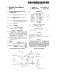
1
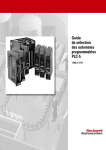
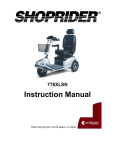
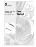
US006105341A
United States Patent [19]
[11] Patent Number:
Campbell
[45] Date of Patent:
[54]
PROCESS THAT USES LIQUID NITROGEN
FOR DISPLACING AIR FROM A
CONTAINER PRIOR TO SEAMING A LID TO
THE CONTAINER
Inventor:
Robert H. Campbell, Brookhaven, Pa.
Assignee: ABC Seamer Technologies, Inc.,
Aston, Pa.
OTHER PUBLICATIONS
“Cost Effective Conversion from Vacuum Packing to Gas
Flushing,” Jescorp Packaging Machinery & Electronics,
copyright dated 1996, downloaded from Jescorp website
(www.jescorp.com/canco.html) on Sep. 8, 1997, 3 pages.
Product catalog description of 3 can seaming machines:
Irregular Can Seaming Machine—BMT: SPS 200; Round
Can Seaming Machine—SRS 200; Can Seaming Machine
(www.optimal—india.com/bubber/catalog.htm) on Sep. 8,
Nov. 20, 1998
1977, 3 pages.
International Search Report for PCT/US98/27254 mailed
Apr. 28, 1999, 6 pages.
Related US. Application Data
Division of application No. 08/996,874, Dec. 23, 1997, Pat.
NO. 5,860,782.
Int. Cl.7 ........................... .. B21D 51/26; B65B 7/28;
B65B 31/04; B65B 55/18; B65B 55/19
US. Cl. ................................. .. 53/432; 53/98; 53/239;
53/402; 53/431; 53/471; 53/488; 53/511;
Assembly view (vertical cross—section thru valves and hoist)
of CAN CO 117 seaming machine, Canco, Greenwich, Con
necticut, date unknown, 1 page (numbered —53—).
Catalog pages for Step Motor Drivers. Introduction to Step
Motor Drivers; SD8055 Microstep Motor Driver; SD8055
Installation. AMCI, pp. 4 and 10—17.
413/6; 413/27; 413/31
(List continued on neXt page.)
Field of Search ............................ .. 53/432, 433, 511,
53/510, 111 R, 400—403, 431, 471, 486,
488, 75, 97, 98, 88, 89, 86, 79, 239; 413/2—7,
26, 27, 31, 40, 41, 43
References Cited
[56]
Aug. 22, 2000
SRS:200:SB with Control Unit BMT: P—200 for Round
Cans, downloaded from Bubber Machine Tools website
Appl. No.: 09/196,810
Filed:
6,105,341
Primary Examiner—James F. Coan
Attorney, Agent, or Firm—Akin, Gump, Strauss, Hauer &
Feld, L.L.P.
[57]
ABSTRACT
A process is provided for displacing air from containers
U.S. PATENT DOCUMENTS
prior to seaming a lid to a container. In the process, a
635,608
648,037
1,862,290
10/1899 Steward .
4/1900 Lef?er .
6/1932 Anderson .
2,150,002
3/1939 Link.
2,216,082
9/1940 Kronquest et al. .
container body is ?lled with contents and is then injected
with liquid nitrogen. A lid is immediately placed on the
container body, and a biasing force is immediately applied
against the lid to maintain the lid on the liquid nitrogen ?lled
container bodies until the container body reaches the seam
ing mechanism. The biasing force is suf?cient to allow a
2,391,684 12/1945 DieZel.
3,033,264
4,633,553
5/1962 Hendrikson .
1/1987 Chronis et al. .
4,662,153
5/1987 Wozniak.
4,961,300
5,228,274
portion of nitrogen gas from vaporization of the liquid
nitrogen to escape from the container body, and to allow air
originally present in the container body to escape from the
10/1990 Mihara et al. .
7/1993
De Man et al. ........................ .. 53/510
5,251,424
10/1993 Zenger et al.
.
5,271,207
5,358,369
5,584,634
12/1993 Epstein et al. .......................... .. 53/432
10/1994 Katou et al. .
12/1996 Okabe et a1. ......................... .. 53/75 X
container body, while preventing surrounding air from enter
ing the container body.
8 Claims, 13 Drawing Sheets
82
OPERATOR
TERMINAL
6,105,341
Page 2
OTHER PUBLICATIONS
Catalog for ET Series Electro—Thrust Electric Cylinder
Catalog, 1890, Parker Motion & Control, Parker Hanni?n
Corporation, Automation Actuator Division, Wadsworth,
Ohio, Jul. 1994.
SLC SOOTM Family of Small Programmable Controllers,
System OvervieW catalog, Publication 1747—2.30,
Allen—Bradley, Milwaukee, Wisconsin, Aug. 1993.
User’s Manual for Allen—Bradley Stepper Controller Mod
ule, Catalog No. 1746—HSTP1, Allen—Bradley, MilWaukee,
Wisconsin, Jun. 1996.
Brochure for PanelvieWTM 550 Operator Terminals/Panel
builderTM 550 SoftWare, Publication 2711—1.3, Allen—Bra
dley, MilWaukee, Wisconsin, Jan. 1994.
“Double Seam Terminology”, date unknoWn, 1 page.
U.S. Patent
mm
Aug. 22,2000
A
Sheet 1 0f 13
6,105,341
U.S. Patent
Aug. 22,2000
Sheet 2 0f 13
6,105,341
Fig. 2
3
FROM
CONTROLLER
54
42
U.S. Patent
Aug. 22,2000
Sheet 3 0f 13
6,105,341
U.S. Patent
Aug. 22, 2000
CONTRQLE
F68ROM 454/42
Sheet 4 0f 13
6,105,341
U.S. Patent
Aug. 22,2000
wow
Sheet 13 0f 13
6,105,341
V
@.mE
6,105,341
1
2
PROCESS THAT USES LIQUID NITROGEN
FOR DISPLACING AIR FROM A
CONTAINER PRIOR TO SEAMING A LID TO
THE CONTAINER
?rst drive may include a servomotor and a linear actuator.
The servomotor receives control data related to the desired
position of the seaming roller With respect to the circum
ferential edge of the container body, and the container lid.
The linear actuator translates a servomotor output to cause
movement of the seaming roller.
CROSS REFERENCE TO RELATED
APPLICATION
This application is a division of application Ser. No.
08/996,874, ?led Dec. 23, 1997, now US. Pat. No. 5,860,
782, originally entitled “CONTAINER SEAMING APPA
RATUS AND METHODS,” the entire disclosure of Which is
Another embodiment of the invention provides a con
tainer seaming machine for performing a seaming operation
10
and a pressure sensor. The seaming chuck holds the lid
?rmly against an end of the container body during a seaming
operation. The other end of the container body is placed on
incorporated herein by reference.
BACKGROUND OF THE INVENTION
on a container body and lid by using a seaming roller. The
machine includes a seaming chuck, a base surface, a drive
the base surface. The drive causes the base surface to move
15
toWard the seaming chuck so that the end of the container
The present invention-relates generally to seaming
body and the lid are held ?rmly against the seaming chuck
machines. A seaming machine is used to seam a lid to a
contents-?lled container body so as to form a sealed con
performing the seaming operation. The end of the container
and so that the container body and lid are in position for
tainer. The seaming machine typically has tWo seaming
rollers associated With the seaming machine to form a
sanitary seam, also called a double seam, betWeen the
container body and the lid.
Conventional seaming rollers are positioned by mechani
cal cams controlled by mechanical drives, gear trains and the
like, all of Which are carefully coordinated and interlinked
20
associated With an output of the drive. The pressure sensor
25
With a drive that rotates the container body With respect to
the seaming rollers. Due to the complex linkages uses in
conventional seaming machines and reliance on primarily
mechanical drives, it is very time-consuming to make
adjustments to a seaming machine When the machine
30
force is immediately applied against the lid to maintain the
lid on the liquid nitrogen ?lled container bodies until the
35
container. As the liquid nitrogen vaporiZes, the resultant
nitrogen gas drives out the air. This process requires precise
timing to ensure that substantially all of the liquid nitrogen
container body reaches the seaming mechanism. The biasing
force is suf?cient to alloW a portion of nitrogen gas from
virtue of its inherent design, is also limited in the range of
different container siZes that it can be adjusted to handle.
When packaging goods Which spoil due to eXposure to air,
Another embodiment of the invention provides a process
to displace air from containers prior to seaming a lid to a
container. In the process, a container body is ?lled With
contents and is then injected With liquid nitrogen. A lid is
immediately placed on the container body, and a biasing
different container siZe is used. The changeover results in
the air is removed from the container before the lid is sealed
thereon. One process for removing the air and Which avoids
the necessity to seam under a vacuum, is to inject liquid
nitrogen into the container before the lid is seamed onto the
measures the force eXerted betWeen the container body and
the lid. The measured force is used to determine the ?nal
position of the drive.
becomes out of tolerance, or if a different siZe container is
used. For example, it may take as long as an entire Workday,
as Well as the swapping of parts, to change a machine if a
lost production time and requires skilled, hard to ?nd,
machine operators. A conventional seaming machine, by
body and the lid eXert a force against each other Which is
determined by the ?nal position of the drive. In this manner,
the ?nal position of the drive is adjustable so that the drive
may cause varying degrees of force to be eXerted betWeen
the container body and the lid. The pressure sensor is
vaporiZation of the liquid nitrogen to escape from the
container body, and to alloW air originally present in the
container body to escape from the container body, While
40
preventing surrounding air from entering the container body.
The biasing force is applied for a period of time Which is
suf?cient to alloW substantially all of the liquid nitrogen to
vaporiZe, and thereby displace substantially all of the air
originally present in the container body. The biasing force
45
may be applied by a spring loaded rail. An apparatus for
performing this process is also provided.
vaporiZes and that no air leaks back into the container before
the lid is seamed on. It is very dif?cult to achieve the precise
BRIEF DESCRIPTION OF THE DRAWINGS
timing.
The foregoing summary, as Well as the folloWing detailed
description of preferred embodiments of the invention, Will
Accordingly, there is a need for seaming machines and
processes Which overcome the problems discussed above.
be better understood When read in conjunction With the
appended draWings. For the purpose of illustrating the
BRIEF SUMMARY OF THE INVENTION
A container seaming machine is provided Which includes
55
a seaming chuck, a seaming roller and a ?rst and a second
drive. The seaming chuck holds a lid ?rmly against an end
of a container body during a seaming operation. The ?rst
drive is connected to the seaming roller and positions the
seaming roller With respect to a circumferential edge of the
lid. The second drive causes rotation of the seaming chuck,
thereby causing rotation of the container body and container
lid. The ?rst drive and the second drive are independently
controllable from each other. A programmable controller
provides the separate control and coordination of the tWo
drives. A method of seaming a lid to a container body by
using the container seaming machine is also provided. The
invention, there are shoWn in the draWings embodiments
Which are presently preferred. It should be understood,
hoWever, that the invention is not limited to the precise
arrangements and instrumentalities shoWn. In the draWings:
FIG. 1 is a schematic illustration of an assembly line
process Which uses a container seaming machine in accor
60
dance With the present invention;
FIG. 2 is an enlarged front elevational vieW of a portion
of the seaming machine of FIG. 1;
FIG. 3 is a top plan vieW of a seaming roller drive for the
seaming machine of FIG. 2, taken along line 3—3 of FIG.
65
2;
FIG. 4 is an elevation vieW of the seaming roller drive of
FIG. 3, taken along line 4—4 of FIG. 3;
6,105,341
3
4
FIGS. 5A—5H are sample display screens and their
respective screen summary reports for a programmable
controller Which is shoWn in FIG. 1 and Which controls the
end of the container body. A ?rst mechanical drive positions
the tWo seaming rollers With respect to a circumferential
edge of the lid. A second drive on the seaming machine
rotates the seaming roller With respect to the chuck, con
tainer body and container lid. There is typically one motor
Which has tWo poWer takeoffs, one for each of the drives. In
seaming machine of FIG. 1; and
FIG. 6 is a schematic illustration of an assembly line
process for removing air from containers prior to seaming
the containers, in accordance With the present invention.
DETAILED DESCRIPTION OF THE
INVENTION
one conventional con?guration, the chuck, container body
and lid remain stationary, and the second drive rotates the
seaming roller around the container body and lid. In another
10
conventional con?guration, a second drive on the seaming
machine rotates the chuck, Which, in turn, rotates the con
In the draWings, the same reference numerals are
tainer body and lid. There are typically tWo seaming rollers
employed for designating the same elements throughout the
on a seaming machine used for food products. The tWo
seaming rollers form a sanitary seam, called a double seam,
several ?gures.
FIG. 1 shoWs an assembly line 10 for moving content
?lled container bodies 12 through a seaming station 14
15
Which seams lids 16 to the container bodies 12 to form
lidded, sealed containers 18. The assembly line 10 includes
a conveyor 20 for moving the container bodies 12 and the
seamed containers 18. The seaming station 14 de?nes a
vacuum chamber 22 having a seaming machine 24 therein.
The individual components of the seaming machine 24 are
described in detail beloW.
The container seaming machine 24 described herein
seams lids to container bodies under a vacuum state. To
accomplish this task, the assembly line 10 further includes
not described in detail herein. The shafts 36 and 38 are
described in detail beloW. While the seaming machine 24 has
tWo seaming rollers, the present invention is equally appli
25
an inlet or entrance feed valve 26 and a discharge or eXit feed
cal cams controlled by mechanical drives, gear trains and the
like, all of Which are carefully coordinated and interlinked
With the second drive that rotates the container body With
respect to the seaming rollers. To change the settings of a
entrance feed valve 26 introduces the container bodies 12 to
the vacuum chamber 22 of the seaming station 14. Vacuum
begins to be pulled on the container bodies 12 as the
conventional seaming machine, such as to accommodate a
container bodies 12 pass through the feed valve 26. The eXit
feed valve 28 removes the lidded, sealed containers 18 from
different container diameter or to correct a “seam out-of
35
The region of FIG. 1 labeled as 30 is a vacuum region, the
highest vacuum occurring in the vacuum chamber 22. Thus,
While not illustrated in FIG. 1, the outlet of the entrance feed
valve 26 and the inlet of the eXit feed valve 28 are in ?uid
tolerance” condition, the entire machine must be shut doWn
and a very time-consuming resetting procedure must be
performed. A changeover to a different container diameter
may take several hours. Furthermore, conventional seaming
machines typically require thousands of dollars of change
parts to handle a different container siZes.
communication With each other and are sealed from the
One important feature of the present invention is that the
seaming rollers 32 and 34 are positioned by drives that are
surrounding environment. An integrated seaming mecha
nism Which has an entrance feed valve 26, a seaming station
14 under vacuum, and an eXit feed valve 28 is conventional,
and thus is not described in detail herein. One eXample of
such a mechanism is a CAN CO 117 seaming machine, made
cable to a seaming machine Which has only one seaming
roller.
Conventional seaming rollers are positioned by mechani
valve 28, each of Which have respective inlets and outlets in
?uid communication With the seaming station 14. The
the seaming station 14.
betWeen the container body and the lid. The ?rst roller
begins to roll the lid and the container body, forming a ?rst
operation roll seam, and the second roller completes the
seam, forming the second operation roll seam. The resultant
seam is airtight.
The seaming machine 24 has tWo such seaming rollers 32
and 34 linked to respective seaming roll shafts 36 and 38.
The rollers 32 and 34 are of conventional design, and thus
independently controllable from, or independent of, the
drive that rotates the seaming rollers 32 and 34 With respect
to a circumferential edge of the lid 16 to be seamed to the
45
by Canco, GreenWich, Conn. The feed valves 26 and 28 in
container body 12. That is, the tWo drives are separate,
such a mechanism use turrets to move the container bodies
mechanically unlinked motive means. There are no
mechanical cams. Adjustments may be made to one drive
12 from the valve inlets to the valve outlets. The feed valves
26 and 28 may be similar to the feed valves in the Canco
machine, or they may be similar to feed valves of other types
Without affecting the other. In this manner, the seaming
roller drive (or seaming roller drives if there are tWo seaming
rollers) may be positioned more easily, and Without having
of conventional vacuum-operated seaming mechanisms.
to shut doWn the machine or adjust any gears or the like
seams under vacuum, the vacuum environment is not a
Within the seaming machine. The seaming roller drives may
even be adjusted While the seaming machine is in operation
necessary feature of the invention, and the seaming may
(i.e., “on-the-?y”) and Without having to stop the seaming
While the disclosed embodiment of the present invention
occur at atmospheric pressure. Thus, the vacuum chamber 55 machine at all. Furthermore, different container siZes may be
run through the same seaming machine With a minimum of
22 is optional, the feed valve 26 need not necessarily draW
eXtra tooling.
a vacuum, and the outlet of the feed valve 26 and the inlet
of feed valve 28 need not necessarily be in ?uid communi
The seaming roller drives must be coordinated With the
drive that rotates the seaming rollers 32 and 34 With respect
cation to maintain a vacuum. A less complex feed process
may also be used in place of the feed valves 26 and 28 to
deliver container bodies 12 to, and remove lidded containers
to a circumferential edge of the lid 16 to be seamed to the
container body 12. In the present invention, this coordina
tion is performed by a controller, preferably, a program
18 from, the seaming station 14.
mable controller Which eXecutes a programmable logic
Seaming machines use seaming heads Which have seam
ing rolls or seaming rollers attached thereto for performing
the seaming function. In one type of seaming machine, a
seaming chuck holds a lid ?rmly against a top end of a
container body so that the lid is held in contact With the top
65
control (PLC) program. The programmable controller pro
vides signi?cantly more ?exibility than the conventional
approach of mechanically synchroniZing seaming machine
drives.
6,105,341
6
5
Referring again to FIG. 1, the seaming machine 24
and 34 for the particular container height, or it Would be
necessary to independently move the seaming rollers 32 and
34 in a vertical direction using drives similar to the drive 50.
The lid 16 is placed on the top end of the container body
includes a ?rst seaming roller drive 40 and a second seaming
roller drive 42. The ?rst seaming roller drive 40 is linked via
the roll shaft 36 to the seaming roller 32, and the second
seaming roller drive 42 is linked via the roll shaft 38 to the
12 before the tWo items enter the feed valve 26. The
mechanism for placing the lids 16 on the succession of
container bodies 12 is not shoWn in FIG. 1. In the embodi
seaming roller 34. The drives 40 and 42 adjustably position
the circumferential edge of the respective seaming rollers 32
and 34 toWard and aWay from a center aXis Acb of the
ment of the invention Which does not seam in a vacuum
container body 12, thereby positioning the seaming rollers
environment, the lid 16 is placed on the container body 12
32 and 34 With respect to the circumferential edge of the lid
16 to perform a seaming operation.
The seaming machine 24 is of the type Wherein a seaming
chuck holds the lid 16 ?rmly against the top end of the
container body during the seaming operation, and a drive
rotates the chuck, thereby causing rotation of the container
body 12 and container lid 16 (and the chuck) in unison. The
before the tWo items are placed on the base plate 48.
To alloW for independent controlling of the respective
15
seaming chuck and drive are schematically shoWn and are
labeled as 44 and 46, respectively. The present invention
may alternatively be used With a seaming machine 24
Wherein a chuck, container body and lid remain stationary,
program, shoWn as a ladder diagram, appears in the Appen
diX. Based on the program, control data is output from the
controller 54 and sent to the respective drives 40, 42, 46 and
50. One purpose of the programmable controller 54 is to
appropriately position the seaming rollers 32 and 34 With
respect to the circumferential edge of the lid 16 during
and a drive rotates the seaming roller around the container
body and lid. In either con?guration, the ?rst and second
seaming roller drives 40 and 42 are independently control
lable from the drive Which rotates the seaming rollers 40 and
42 With respect to the chuck. In the disclosed eXample of the
present invention, the ?rst and second seaming roller drives
drives, the assembly line 10 preferably includes a program
mable controller 54 Which eXecutes a programmable logic
control (PLC) program stored therein. A sample PLC
rotation of the container body 12, lid 16 and chuck 44 so as
25
40 and 42 are thus independently controllable from the drive
to perform a seaming operation. Another purpose of the
programmable controller 54 is to control the base plate drive
50 so that the base plate 48 is lifted to the appropriate ?nal
position. The program thus coordinates the seaming opera
tion in accordance With the stored program and thereby
replaces conventional mechanical linkages Which perform
46 that rotates the chuck 44, as described in more detail
hereafter.
The seaming machine 24 also has a vertically movable
base surface or base plate 48 for receiving the container
similar functions.
The programmable controller 54 includes an operator
body 12 and for lifting it toWards the chuck 44. The base
plate 48 is lifted by a base plate drive 50 Which is linked via
values to be entered into the program, and a display 58 for
shaft 52 to the base plate 48. In use, a container body 12 and
an unattached lid 16 resting on the top end of the container
body 12 are placed on the base plate 48, and the container
body 12 and unseamed lid 16 move toWard the chuck 44 a
input panel 56 for alloWing at least some of the operating
interfacing With the operator during inputting and for com
municating operating status. The programmable controller
35
predetermined vertical distance until the top end of the
container body 12 and lid 16 are held ?rmly against the
chuck 44. The top end of the container body 12 and the lid
16 thus eXert a force against each other Which is determined
by the ?nal position of the base plate 48, as determined by
the action of the drive 50. The container body 12, lid 16 and
chuck 44 remain in the ?nal position during the seaming
operation. After the seaming operation is completed, the
45
54 may optionally receive input data from automated mea
suring devices or sensors placed along the assembly line 10.
For example, there may be a container body diameter sensor
60 and a container height sensor 62 located prior to the
seaming station 14. Data from these sensors may be used in
place of an operator input values or preset values to set
parameters of the program Which Will control the drives. In
particular, the diameter sensor 60 may be used to control the
roller drives 40 and 42 and the chuck drive 46, Whereas the
height sensor 62 may be used to control the base plate drive
50.
base plate drive 50 moves the base plate 48 doWnWard to
Roller drives 40 and 42 may periodically require ?ne
alloW the lidded container 18 to be released and to alloW a
position adjustments due to Wear at contact surfaces or due
neW container body 12 to be placed on the base plate 48. The
to play in linkage components. An additional feedback
base plate drive 50 is independently controllable from the
sensor 64 may be located after the seaming station 14 to
roller drives 40 and 42, and from the chuck drive 46, as
obtain data regarding the quality of the seam (e.g., its Width,
body hook and cover hook) of seamed containers 18. The
feedback data may be analyZed, compared to desired values,
and used to make the ?ne position adjustments to the
appropriate drives. Seamed containers may also be manually
described in more detail hereafter.
In an alternative embodiment of the invention, the base
plate 48 is ?Xed, and the chuck 44 moves vertically doWn
Ward to hold the container body 12 and lid 16 ?rmly together
against the base plate 48. In this alternative embodiment, the
55
drive 50 Would be linked via the shaft 52 to the chuck 44.
In the preferred embodiment of the invention shoWn in the
ally entered into the operator input panel 56.
Each production run of containers requires speci?c drive
instructions based upon the container siZe (e.g., diameter
?gures, the seaming rollers 32 and 34 do not move vertically.
Accordingly, When a container body is properly positioned
in the seaming machine 24, it is only necessary to move the
seaming rollers 32 and 34 toWard the center aXis of a
container body 12 to properly position the rollers 32 and 34
to perform a seaming operation. HoWever, if the ?Xed base
plate alternative embodiment is used, it Would be necessary
to either link the seaming rollers 32 and 34 (and related
parts) together With the vertically movable chuck 44 to
obtain the proper vertical position for the seaming rollers 32
eXamined by quality control personnel, and based upon
visual inspection, ?ne position adjustments may be manu
and height), and desired qualities of the seam (e.g., Width,
body hook and cover hook). These factors are processed by
the programmable controller 54 and used to create a set of
instructions. The set of instructions are used to output drive
65
control data for each of the seaming machine drives. For
eXample, a container body having a three inch diameter and
a siX inch height requires a ?rst set of instructions, including
position instructions for the roller drives 40 and 42 (to
6,105,341
7
8
appropriately position the seaming rollers 32 and 34), rota
84 is ?xed to a housing 86 of the seaming machine 24. The
tion instructions for the chuck drive 46 and ?nal position
instructions for the base plate drive 50, Whereas a container
body having a tWo inch diameter and a four inch height
requires a second set of instructions that Will be completely
drive 42 includes a servomotor 68 and a linear actuator 70.
The servomotor 68 has an input for receiving control data
from the programmable controller 54 related to the desired
position of the seaming roller 34 With respect to the circum
ferential edge of the container body 12 and the container lid
16, and an output. The output of the servomotor 68 is
different from the ?rst set of instructions.
The set of instructions may be initiated at the start of a
production run of similar containers to be seamed in the
same manner. Alternatively, the set of instructions may be
modi?ed during the production run based upon feedback
10
connected to the linear actuator 70 Which translates the
servomotor output. The linear actuator 70 has an output shaft
72 Which is pivotally connected to one end of a linking plate
74. The other end of the linking plate 74 is ?xedly secured
to the top surface of the roll shaft 38. Another linking plate
data from the sensor 64. Another alternative embodiment
uses the diameter and/or height sensors 60 and 62 to de?ne
a neW set of instructions “on the ?y” Without having to stop
the seaming machine 24. In this manner, a single production
run may include containers of different siZes and/or seam 15
88 is ?xedly secured at one end to the bottom surface of the
roll shaft 38 and at the other end to the seaming roller 34. In
this manner, movement of the output shaft 72 out of the
linear actuator 70 causes rotation of the roll shaft 38 in a
types.
counterclockWise direction, Which, in turn, causes the seam
ing roller 34 to move toWard the center axis Acb of the
The container diameter may also be used to automatically
select “on-the-?y” the appropriate chuck 44 from a plurality
of chucks for automatic mounting to a seaming machine.
The seaming machine 24 shoWn in the ?gures does not have
this capability, although it could be provided, if desired. In
container body 12. FIG. 2 shoWs the seaming roller 34 in
contact With the circumferential edge of the lid 16 and thus
in the position for performing a seaming operation.
this manner, a very Wide range of container diameters can be
LikeWise, movement of the output shaft 72 into the linear
processed continuously by the same seaming machine With
out requiring any doWntime for manually changing chucks.
clockWise direction, Which, in turn, causes the seaming
Since the programmable controller 54 has complete con
actuator 70 causes rotation of the roll shaft 38 in the
25
trol over the drive 46, and because the drive 46 is not
roller 34 rotates about its center axis in a conventional
mechanically linked to the drives 40 and 42, the direction of
the seaming process can be selected. In the seaming machine
24 of FIG. 1, this means that the container body 12 can be
spun in reverse during a seaming operation, if desired,
manner.
To obtain precise control of the drive 42, the servomotor
68 is preferably a stepper motor Which accepts control data
from a programmable controller, and the linear actuator 70
is preferably a ball screW mechanism. Alternatively, the
linear actuator 70 may be a pneumatic cylinder. Such
thereby maximiZing the strength of certain composite con
tainers depending upon hoW the composite material is
Wound (e.g., clockWise or counterclockWise around a
mandrel). Such composite containers Would otherWise be
Weakened by a forWard rotation during a seaming operation.
servomotor and linear actuator combinations 68 and 70 are
35
Poor seams are sometimes the result of insuf?cient or
With a remote operator terminal 82. This alloWs an operator
at a remote site to operate the seaming machine 48, program
excessive force being applied betWeen the container body 12
and the lid 16 during the seaming operation. Also, When the
or reprogram the controller 54, and to remotely perform
container bodies 12 are made of cardboard or a soft poly
meric material, excessive force may cause crushing or
diagnostics.
To simplify the subsequent explanation of the invention,
the seaming machine 24 is described With respect to only a
45
34 and its corresponding drive 42. The remaining discussion
of these components is equally applicable to the seaming
roller 32 and its drive 40. Also, the position coordination of
tWo seaming rollers With respect to each other Which is
the output shaft 72 of the linear actuator 70 associated With
the drive 50 is directly connected to the shaft 52 Which
extends from the base plate 48. The connection is along a
common vertical axis. In FIG. 1, the shafts 52 and 72 appear
described in detail herein.
HoWever, the process generally Works as folloWs:
as one continuous shaft, even though there are actually tWo
55
in contact With the lid.
of the base plate 48. As a result, the drive 50 is program
mable to cause varying degrees of force to be exerted
betWeen the container body 12 and the lid 16. Data obtained
into contact With the lid to complete the seam.
about its center axis Am. The roll shaft 38 rotates Within a
bushing (not shoWn) of a shaft housing 84. The shaft housing
shafts linked together. Alternatively, the shaft 52 may be
eliminated, and the linear actuator’s output shaft 72 may be
directly connected to the base plate 48. This con?guration
alloWs for precise, computer-controlled height adjustments
(2) Next, the ?rst roller is moved aWay from (and out of
contact With) the lid, and the second roller is brought
(3) When the seam is completed, the second roller is
moved aWay from the lid.
FIGS. 2—4 shoW detailed vieWs of one preferred embodi
ment of the drive 42 and its linkages to the seaming roller 34.
Referring to FIG. 2—4, the drive 42 is linked via the roll shaft
38 to the seaming roller 34. The roll shaft 38 is rotatable
bulging of the seamed container sideWalls. All of these
problems can be minimiZed or eliminated by the present
invention.
Referring to FIG. 1, the drive 50 associated With the base
plate 48 is preferably similar to the drive 42, and thus also
includes a servomotor 68 and a linear actuator 70. HoWever,
required to create a double seam is Well knoWn and thus not
(1) The ?rst roller is brought into contact With the lid, and
begins to roll the lid and the container body. While the
?rst roller is contacting the lid, the second roller is not
Well-knoWn to those skilled in the art. Accordingly, further
description thereof is omitted for purposes of brevity and
convenience only and is not limiting.
The programmable controller 54 also includes a remote
communication module 80 for bidirectional communication
single seaming roller and drive, particularly, seaming roller
roller 34 to move aWay from the center axis Acb of the
container body 12. During a seaming operation, the seaming
from the feedback sensor 64 may also be used to make ?ne
adjustments to the ?nal position of the base plate 48.
To obtain even better control of the force exerted betWeen
the container body 12 and the lid 16, a pressure sensor 76
65
may be associated Within the drive 50 so that an immediate
indication of the force may be detected and used for feed
back control. In this scheme, a desired force is preset by the
6,105,341
9
10
U0 Analog Module—NIO4I and NIO4V
Operator Terminal—2711 PanelVieW 550 Operator
Terminal, Panelbuilder 550 SoftWare
programmable controller 54. In operation, the program
mable controller 54 sends instruction data to the drive 50 to
cause movement of the base plate 48 toWard the chuck 44.
The output of the pressure sensor 76 is continuously trans
Remote communication module—1746-BAS Basic Mod
mitted to the programmable controller 54 and compared to
the desired force. The comparison data is used to set the ?nal
position of the drive 50.
ule or 1747-KE Interface Module
The 1746-BAS Basic Module provides limited remote
capability. The 1747-KE Interface Module provides full
The pressure sensor 76 may be a strain gage attached to
remote capability so that all of the functions of the program
the linear actuator’s output shaft 72. Alternatively, the
mable controller 54, including the functions of adjusting
pressure sensor 76 may be an air pressure sensor if the linear 10 drive instructions based on sensed container types and seam
actuator 70 is a pneumatic cylinder.
feedback data, can be performed remotely.
Controller-driven drives provide signi?cant advantages
for the seaming machine 24, some of Which are discussed
beloW.
It is sometimes desirable to spot clinch containers during
A sample ladder diagram for implementing seaming
machine control via the Stepper Controller Module is shoWn
15
a seaming operation. Spot clinching is performed on a
1. Con?gure the Stepper Controller Modules.
2. Start, stop and jog the seaming machine 24 (sends
seaming machine by intermittently engaging and disengag
ing the seaming rollers from a seaming position during
rotation of the seaming rollers With respect to the chuck,
container body and lid. It is dif?cult, if not impossible, to use
a conventional seaming machine for both spot clinching and
complete airtight seaming. In one knoWn technique, a rail
substation is used When spot clinching With a conventional
seaming machine.
The seaming machine 24 is easily adaptable to spot
25
complete seaming operations. To perform spot clinching, it
roller engaging and disengaging instructions during rotation
30
the seaming roller 34 is controlled independent of the
seaming chuck drive 46, it is not necessary to make any
35
spot clinching, to miX spot clinching and complete seaming
operations in the same machine, or to perform spot clinching
folloWed by complete seaming on the same container.
REFERRED COMPONENTS OF
PROGRAMMABLE CONTROLLER 54
40
45
These display screens may be generated using a PV550
Keypad and Touch Screen With softWare version FRN
200-2XX, available as Allen-Bradley Catalog Part no. 2711
B5A3.
COMPONENTS OF DRIVES 40, 42, 50
Electric Cylinder, available from Parker Motion & Control,
Parker Hanni?n Corporation, Automation Actuator
Division, WadsWorth, Ohio. Each of these drives have a ball
One preferred embodiment of the invention requires a
total of ?ve container revolutions to seam a container, 21/2
revolutions for the ?rst (initial) seam and 21/2 revolutions for
the second (?nal) seam. The precise number of revolutions
depends upon a myriad of factors, including the desired
55
properties of the containers and the seams.
LIQUID NITROGEN INJECTION
Many types of containers are seamed under vacuum so
SLC 500 Modular Controller With an SLC 5/03 processor.
60
that the container interiors have substantially no air after
they are seamed. In this manner, the container contents
cannot become spoiled by eXposure to oXygen in air trapped
in the sealed container. Nuts are one product Which is easily
1746-IV16
120/240 VAC, 16 output Discrete Output Module—
Catalog No. 1746-OW16
VAC/VDC Relay, 16 output Discrete Output Module—
Catalog No. 1746-OW16
tive screen summary reports are shoWn in FIGS. 5A—5H.
ROTATIONS FOR SEAMING OPERATION
50
Catalog No. 1746-HSTP1. Alternatively, one or three or
Memory Module—Catalog No. 1747-M11 12K Words
PoWer Supply—Catalog No. 1746-P2
24 VDC, 16 input Discrete Input Module—Catalog No.
loWered for cleaning and maintenance.
Referring to function 2 above, the chuck drive 46 may
also be controlled by a stepper motor Which Would require
more precise control signals than poWer on/off signals used
in the present embodiment of the invention.
Sample PanelVieW 550 display screens and their respec
screW and a stepper motor.
cation No. 1747-230. A User’s Manual for the Stepper
Controller Module is available from Allen-Bradley and has
more Stepper Controller Modules may be used, depending
upon the needs of the overall system.
One preferred con?guration of the SLC 500 program
mable controller has the folloWing components:
Terminal to alloW for seaming roll adjustments.
drives 40, 42 and 50 are the ET Series Electro-Thrust
Controller Modules are both available from Allen-Bradley,
MilWaukee, Wis. The output of the Stepper Controller
Module provides the control data for the respective drives.
Asystem overvieW of the SLC 500 family of programmable
controllers is available from Allen-Bradley and has Publi
. Provide an interface With PanelVieW 550 Operator
One family of drives Which are suitable for use as the
One preferred embodiment of the present invention is
implemented using an SLC 500 programmable controller,
equipped With preferably tWo Stepper Controller Modules.
The SLC 500 programmable controller and the Stepper
GUI-P)
. SynchroniZe machine speeds and stepper motors.
. Provide safety stops to protect machinery.
. Track production and machine running hours.
7. Provide circuitry to alloW valves to be raised and
is only necessary to program the controller 54 With seaming
internal adjustments to the seaming machine 24 to perform
signal to AC motor inverter, also controls machine
speed). This function also includes controlling poWer to
the chuck drive 46 and the feed valves 26 and 28.
20
clinching, and to a combination of spot clinching and
of the seaming chuck drive 46. For eXample, if four clinches
are desired, the controller 54 Would be programmed to
engage the seaming roller 34 at 0°, 90°, 180° and 270°. Since
in the AppendiX. The ladder diagram performs the folloWing
machine control functions:
spoiled by eXposure to oXygen. Seaming machines Which
operate in a vacuum environment, such as the seaming
65
machine of FIG. 1, are complex, expensive, and dif?cult to
operate, compared to seaming machines Which do not oper
ate in a vacuum environment.