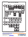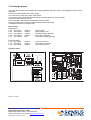
1
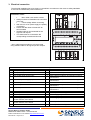
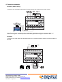
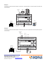
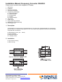
Installation Manual Frequency Converter FM-2D/K
Pulse-current converter with integrated LC-Display
1.
2.
3.
4.
5.
6.
7.
8.
9.
10.
Description
Installation
Electrical connection
Connection examples
Programming and display
5.1 Menu description
5.2 Menu structure
5.3 Programming
5.4 Pulsers
5.5 Factory settings
Limit points
M-Bus output
Surge / lightning protection
Maintenance / Troubleshooting
Exchanging fuses
1. Description
The FM-2D/K is a microprocessor controlled frequency converter with integrated display for programming
and flow values. It transforms input pulses of one or two meters into proportional current for flow indication.
The pulses are converted to:
● Standardised current (0/4 ... 20mA)
● Pulse totalisation
● M-Bus data protocol
● LC-Display values
2. Installation
● Top hat rail mounting
● Wall mounting
Sensus Metering Systems GmbH
Hannover D-30880 Laatzen • Meineckestraße
Further information on our website http://www.sensus.com
MS 5200 GB • Page 1 of 11
3. Electrical connection
The electrical installation has to be done by a specialist in accordance to the common safety standards.
It must not be installed with power switched on.
Installation notice:
•
•
•
•
•
•
Max. cable cross section 2.5mm²
Always connect an Earth/Ground, even when
using 24V
•
Check voltage before connecting
With 24V AC or DC power supply the polarity
is irrelevant
Please see data sheet LS 5200 INT for
technical data
Shielded cable is recommended for the
signal in and outputs
The shield must be connected to the
corresponding terminals and Ground
* when cable length exceeds 3m we recommend
using shielded cable for all signal input and outputs
1
2
3
4
5
6
7
8
9
10
11
12
13
14
15
Terminal description
Lower terminals (from right to left)
1 Screen / Shield
2 M-Bus / MiniBus output
3 M-Bus / MiniBus output
4 Open Collector output for flow direction signal or
limit switch B
24V AC/DC power supply input
5 Open Collector output for flow direction signal or
limit switch B
Current output 0/4-20mA Forward flow
6 Screen / Shield
Current output 0/4-20mA Reverse flow
7 Open Collector output for flow direction signal or
limit switch A
Current output 0/4-20mA Common
8 Open Collector output for flow direction signal or
limit switch A
Pulse output forward flow
9 Pulse input Sensor 2 Common
Pulse output forward flow
10 Pulse input Sensor 2 Signal
Pulse output reverse flow
11 Power supply output +12V 10mA for Sensor 2
Pulse output reverse flow
12 Screen / Shield
Power supply output + ; for electromechanical
13 Power supply output +12V 10mA for Sensor 1
remote counters; 24V 120mA
Power supply output - ; for electromechanical
14 Pulse input Sensor 1 Common
remote counters; 24V 120mA
Screen / Shield
15 Pulse input Sensor 1 Signal
Upper terminals (from left to right)
Mains power input 115/230V
Mains power input 115/230V
Ground / Earth
24V AC/DC power supply input
Sensus Metering Systems GmbH
Hannover D-30880 Laatzen • Meineckestraße
Further information on our website http://www.sensus.com
MS 5200 GB • Page 2 of 11
4. Connection examples
Example 1 (default setting)
Connection of a combination watermeter, flowrate indicator and a passive 24V-remote counter
Note: There can be no reverse flow with a combination meter due to the built in non-return valves and
ratchet in the register. If an HRI pulser is used on the bypass meter the type A1 should be used.
Example 2
Connection to 2 water meters with forward/reverse flow, 2 flowrate indicators, balance counter and inductive
MiniPad.
Supply
24V AC/DC
forward
reverse
+20
+20
0
24V
N
AC/DC
Uout
12345678
FM-2D/K
L
0
Flowrate
indicator
Ground
A
M-Bus
Ground
B
Direction
Sensor 2
U+
Pulse
Sensor 1
U+
+/- 123456
WPD with
Opto OD 01
WPD with
Opto OD 01
Sensus Metering Systems GmbH
Hannover D-30880 Laatzen • Meineckestraße
Further information on our website http://www.sensus.com
MS 5200 GB • Page 3 of 11
Electronic
balance counter
MiniPad
Example 3
Connection to a water meter with forward / reverse flow, 1 flowrate indicator, 2 remote counters, limit switch and
electrical M-Bus.
counter
forward
0
0
1232456
reverse
+20
-20
24V
N
AC/DC
Uout
12345678
FM-2D/K
L
1232456
Flowrate
forward/
reverse
Power supply
230V/AC
or
115V/AC
Ground
WPD with
Opto OD 01
Sensor 1
U+
Sensor 2
U+
A
M-Bus
B
M-Bus
Repeater
+
U
Limit switch
Example 4
Connection to a water meter with forward / reverse flow, a SPC or PLC system with current and pulse input and
2 limit switches.
Power supply
230V/AC
or
115V/AC
Ground
N
SPC
Pulse
SPC
4 … 20 mA
24V
AC/DC
12345678
Uout
FM-2D/K
L
Flowrate
WPD with
Opto OD 01
Sensor 1
U+
Sensor 2
U+
A
B
+
U
-
+
U
-
above
below
Limit switch
Sensus Metering Systems GmbH
Hannover D-30880 Laatzen • Meineckestraße
Further information on our website http://www.sensus.com
MS 5200 GB • Page 4 of 11
M-Bus
5. Programming and Display
5.1. Menu description
The menu structure of the FM-2D/K has 4 loops, which are assigned with symbols.
By pressing the 5 buttons the user can move through the menu. The menu loops are rotating. The particular
menu function is displayed as a symbol in the status line (bottom line) of the LC-display.
In the right hand side of the display up to 5 dots are displayed, indicating which buttons are active and can be
pressed to navigate through the menu. The buttons have the following functions:
top
bottom
left
ahead
right
middle
move one loop above / change a digit or a parameter
move one loop below / change a digit or a parameter
within a loop move one function ahead / within a menu function move one digit/parameter
within a loop move one function back / within a menu function move one digit/parameter back
open a menu function for changing or storing parameters
Symbols
100
100
Symbols of status line (bottom line)
Loop programming
Loop reading of programming values
Loop reading of meter values
Loop reading of statistics values
A
B
C
D
Loop programming
Loop reading programming data
Loop reading meter values
Loop statistics values
Programming data stored
Programming data can be changed
Summation of pulse inputs
Subtraction of pulse inputs
Choice of sensor type
E
Pulse value sensor 1
E1=
Pulse value sensor 2
E2=
- 100 Qmax (corresponds to 20mA)
+
- … Current output and damping
+
Limit switches and hysteresis
Pulse value Open collector output
=
0=
Start index
Pulse value and status of relais output
=
K=?
Open collector output
Test mode
Test
Reading balanced volume and current flowrate
+
Reading balanced volume
Reading current flowrate
+
R
Reading reverse volume
Extreme value Maximum (resetable)
+
Extreme value Minimum (resetable)
+
- 1 Extreme value Maximum 3 hour value
+
- 1 Extreme value Minimum 3 hour value
+
upper limit is passed
lower limit is passed
current value is within the limits
Display of active buttons
Sensus Metering Systems GmbH
Hannover D-30880 Laatzen • Meineckestraße
Further information on our website http://www.sensus.com
MS 5200 GB • Page 5 of 11
5.2. Menu structure
Menu structure FM-2D/K
5
1
Programming
loop
Password
Input E1
Pulse value
Pulse inputs
Qmax
(corresponds to
20mA)
Input E2
Pulse value
A
“1234”
default
setting
E1
Opto uni
Opto uni
Opto bi
Opto bi
Inductive in1 (0°)
Inductive in2 (90°)
Inductive in1(pulse)
Inductive in2 (F/R)
Reed
Reed
Namur o.c.
Namur o.c.
Limit switch
Hysteresis
Open collectoroutputs
Limit switch A
Limit switches
A: GW o
B: GW u
0 … 110 %
Hysteresis A
0 … 110 %
0,001 … 9999
0,001 … 9999
ltr
ltr
E2
New password?
XXXX
Pulses
A: variable pulse
B: direction
Current output
Damping
0,001 … 9999
m³
h
cft
cft
ltr
min
Imp Gal
Imp Gal
cft
s
US Gal
US Gal
Imp Gal
Current
+
+/0 - 20
4 - 20
US Gal
Damping
0
.
..
15
Pulse output
open collector
Start index
XXXXXXXX m³
Pulse output
Relay
Test mode
+
On
Start
+/-
Off
Stop
0,001 … 9999
+
Limit switch B
m³
+/-
ltr
0,001 … 9999
cft
m³
0 … 110 %
Imp Gal
ltr
Hysteresis B
US Gal
cft
0 … 110 %
Imp Gal
US Gal
2
View
programming
values loop
Type of pulsers
Pulse value
E1
B
Open collector
outputs
3
Pulse value
E2
View meter
values loop
Index (balanced)
and flow rate
Index (balanced)
(big digits)
Serial Number
and Version
Qmax
(absolute)
Qmax
(corresponds to
20mA)
Output pulse value
balance counter
and
1
Open collector output
Current flowrate
(big digits)
Limit switch
high/low
and Hysteresis
Current output
and Damping
Start index
Reverse volume
Relay output
on/off and pulse values
Current flowrate
(% of Qmax)
2
3
C
4
View statistical
values loop
Qmin
(absolute)
Qmax
(0 … -3h)
Qmin
(0 … -3h)
4
D
5
XXXX m³/h
XXXX m³/h
XXXX m³/h
XXXX m³/h
xx h : xx min
xx h : xx min
xx h : xx min
xx h : xx min
Qmax
(-3 … -6h)
Qmin
(-3 … -6h)
Reset
yes/no
Reset
yes/no
XXXX m³/h
XXXX m³/h
xx h : xx min
xx h : xx min
Qmax
(-21 … -24h)
Qmin
(-21 … -24h)
XXXX m³/h
XXXX m³/h
xx h : xx min
xx h : xx min
Notice: The time data displayed in the statistics loop are based on the time of reading, e.g.: if the time of
reading is 8:00 am and the FM-2D/K displays 02h:45 min. This means time of the event was 5:15 am.
Sensus Metering Systems GmbH
Hannover D-30880 Laatzen • Meineckestraße
Further information on our website http://www.sensus.com
MS 5200 GB • Page 6 of 11
1
5.3. Programming
All parameters of the FM-2D/K are freely programmable. In loop A the programming is done. After entering the
password (factory setting: 1234) the programming may be done. By pressing the middle button the lock for
programming of the first menu function is opened. All possible settings are listed in the menu. By pressing the
middle button again the changed parameters are stored. Pressing the right button moves to the next parameter.
The following parameters must be set:
● Type of pulser, combination of sensors and input pulse value
● Qmax (value, which corresponds to 20mA, full-scale)
Once these settings have been entered the FM-2D/K is ready for operation. All further settings only have to be
setup, if the particular function is used.
Notice:
● The unit chosen for the open collector output and position of the decimal point is used also for the internal
display of volumes.
Example:
Open collector output:
00.01 m³
Display:
XXXXXX.XX m³
● The Input types and the Pulser description:
Input type
Opto uni
Opto bi
In1 0˚ / In2 90˚
In1 puls / In2 VR_
Reed
Namur o.c.
Pulser description
Sensus pulser OPTO 01-04 or OD 01-04 (totalisation only in one direction) DIN 19234
Sensus pulser OPTO 01-04 or OD 01-04 (totalisation forward / reverse) DIN 19234
Pulser with 2 inductive probes with 90˚ offset signal for forward/reverse totalisation eg.
Sensus pulser K07/08/11/12
Pulser with 2 channels, channel 1 for pulses channel 2 for direction signal (contact open
= forward, contact closed = reverse)
Potential free contact (Reed or relay)
All pulsers that conform to DIN 19234 or open collector pulsers.
Under ‘Pulse inputs’ between E1 and E2 a “+” or “-” can be set. This indicates the type of channel combination,
“+” means both channels will be added together, “-” means that E2 will be subtracted from E1
5.4. Pulsers
Pulser
Relay contact or Reed pulser
eg. RD 01; RD 02; REED 01; REED 02; K01; K02
Sensus optical pulser with flow direction
recognition . OD 01 ... 04; OPTO 01 ... 04
Sensus optical pulser with flow direction
recognition but with reverse pulse suppression eg.
OD AM
Sensus Inductive pulser
eg. K06; K10
Sensus Inductive pulser
eg. K08; K12
Sensus Inductive pulser
HRI Type A2 (One forward and one reverse pulse
output)
Sensus Inductive pulser
HRI Type A1 (balanced forward pulses) The type
A1 should be used for combination meters if the
bypass meter of a combination meter has an HRI
output and the main meter uses an optical or reed
pulser.
Pulser that conforms to DIN 19234
Open Collector outputs
3-wire Pulser*
Terminal
(Bottom row)
14/15 or 9/10
FM-2D/K setting
14/15 or 9/10
Opto bi
14/15 or 9/10
Opto uni
14/15 or 9/10
Namur o.c.
Sensor 1: 14/15; Sensor 2: 9/10
induktiv 0°/90°
14/15 and 9/10
Namur o.c.
14/15 or 9/10
Namur o.c.
14/15 or 9/10
Namur o.c.
U+: 13 ; pulse: 14/15 or
U+: 11; pulse 9/10
* with 3-wire pulsers, the transistor output must switch to earth / ground
Sensus Metering Systems GmbH
Hannover D-30880 Laatzen • Meineckestraße
Further information on our website http://www.sensus.com
MS 5200 GB • Page 7 of 11
Reed
Namur o.c.
5.5. Factory settings
Input 1 programmed as Opto bi, pulse value 1 liter
Input 2 programmed as Opto bi, pulse value 1 liter; channel combination +
Qmax (represents 20mA) = 360 m3/h
Current output 4…20mA, Damping 6
Open collector output: variable pulse, pulse value +/- 1 m3
Relay pulse output activated, pulse value +/- 1 m3
M-Bus primary address 0
6. Limit points
The limit point A is switched on when the flow falls short of the programmed value. The limit point B is switched
on when the flow exceeds the programmed value. The switching hystersis can be set for each of the limit points.
The limit point and hysteresis can be set separately for each contact. The limit switch points and the hysteresis
points correspond to the programmed Qmax value in percent. The points refer to the value set as Qmax
(As a percentage)
Example:
Qmax = 200 m3/h
Limit value = 10%
Hysteresis = 1%
With these values the limit point is 20m³/h and the Hysteresis is 2m³/h. This means:
for upper limit:
switch-on at flow over 20m³/h, switch-off at flow under 18m³/h.
for lower limit:
switch-on at flow under 20m³/h, switch-off at flow over 22m³/h.
7. M-Bus output
The FM-2D/K can be readout via M-Bus or MiniBus. See point 3 for the connection terminals. The M-Bus
transmission protocol corresponds to IEC 870.
M-Bus Readout values:
FM-2D/K serial number
volume
current flowrate
minimum flowrate
time of minmum flowrate
maximum flowrate
time of maximum flowrate
reverse volume
The FM-2D/K supports Primary and Secondary addresses (Manufacturer, Meter ID, Device version number and
device type coding). The baud rate is automatically set to either 300 or 2400 baud. Programming of the M-Bus
settings is done either with M-Bus compatible Collecting station or service software (eg.Sensus MiniCom),
through a level converter. Alternatively a Minipad connected to the MiniBus output of the FM-2D/K can be
connected to a PC using a PC-serial cable MDK (inductive readout), can be used to program the FM-2D/K. The
command to set the primary address of the FM-2/K is described in the M-Bus specifications. After setting up the
primary address, the FM-2D/K is ready to be read out via M-Bus eg. with the DOKOM CS collecting station
software. After receiving the readout command “REQ_UD2”, the FM-2D/K will transmit its data telegram. The
telegram complies with the “variable protocol” of the M-Bus standard and consists of the Data header followed
by 10 data fields. Its structure remains constant.
The data fields that follow the header:
No.
Description
Data type
1
Serial number
8 digit BCD
2
Current balanced volume
8 digit BCD
3
Current flowrate
4 byte Integer
4
Minimum flowrate
4 byte Integer
5
Time in hours since minimum
1 byte Integer
6
Time in minutes since minimum
1 byte Integer
7
Maximum flowrate
4 byte Integer
8
Time in hours since maximum
1 byte Integer
9
Time in munutes since maximum
1 byte Integer
10 Reverse flow volume
8 digit BCD
The minimum and maximum values can only be reset on the FM-2D/K’s LC-Display.
The secondary address is factory set as the FM-2D/K serial number.
Sensus Metering Systems GmbH
Hannover D-30880 Laatzen • Meineckestraße
Further information on our website http://www.sensus.com
MS 5200 GB • Page 8 of 11
MiniBus Readout values: Serial number of FM-2D/K
Current balanced volume
8. Surge / lightning protection
In high lightning / surge risk areas or using long cables the following over-voltage protection is
recommended:
Sensus Metering Systems GmbH
Hannover D-30880 Laatzen • Meineckestraße
Further information on our website http://www.sensus.com
MS 5200 GB • Page 9 of 11
9. Maintenance / Troubleshooting
The FM-2D/K operates without any necessity of maintenance. The table below shows a selection of possible
errors and their elimination.
Error symptom
Cause
LC display is not working
Power supply failure
No current output
Display indicates a flowrate
No pulse output but internal
display counts the volume
Flowrate display “0” and no
output pulses but the water
meter is working and the
pulser is connected
FM-2D/K refuses
programming
Display shows “over”
1. Check supply voltage
2. if 230V: check internal voltage selector and
fuse F 921
3. if 24 V: check fuse F922 and replace if fused
Break in the current output 1. Check cable connection
circuit
2. Check current output using the test mode
3. Check the connected indicator
4. Check fuse F 38 and replace if fused
Break in the pulse output
1. Check cable connection
circuit
2. Check pulse output using the test mode
3. Check the external totaliser and its power
supply
4. Check fuse F 99
Relay output is set as “off” Activate the relay pulse output
Break in the pulse input
1. Check the settings of FM-2D/K
circuit
2. Disconnect the pulser, set the pulser to ‘Reed
o.c.’ and repeatedly short-circuit the sensor
terminals (+) and (-) with a wire or paperclip.
DO NOT SHORT-CIRCUIT THE POWER
SUPPLY!!
- If then flowrate is displayed: replace pulser
- If not: check fuses F 18, F111 and F121
1. Wrong parameters
1. Check parameters
2. The wrong password
2. Check password
has been entered
The input frequency is
1. Check settings (increase Qmax and check
above 1kHz. Possibly due
pulse value)
to a contact bounce of a
2. Exchange pulser (Opto or inductive)
reed switch
3. Use contact protection relay to prevent
bounce
Exchanging fuses is described in section 10 of this manual.
Sensus Metering Systems GmbH
Hannover D-30880 Laatzen • Meineckestraße
Further information on our website http://www.sensus.com
MS 5200 GB • Page 10 of 11
Remedy
10. Exchanging fuses
The Inputs and outputs of the FM-2D/K are protected against damage by fuses. Exchanging the fuses is done
as follows:
● Disconnect the FM-2D/K from power supply
● unscrew the 4 screws at the front of the device
● remove electrical connection terminals above and below (wires can be connected)
● remove housing from top hat rail
● remove display and printed circuit boards from the housing
● open the fuse holder, check fuse and change the fuse if necessary
● assemble the device in reverse order
Size of fuses
Supply board
F 38
fuse 32mA
F 99
fuse 315mA
F 921 fuse 630mA
F 922 fuse 630mA
F 91
fuse 100mA
medium
medium
medium
medium
slow
current output
output supply circuit
secondary supply (internal)
24V supply (external)
mains power supply (primary)
Processor board
F 111 fuse 32mA
F 18
fuse 32mA
F 121 fuse 32mA
medium
medium
medium
input circuit sensor 1
12V supply for sensors
input circuit sensor 2
Layout of fuses
edition 14.10.2004
Sensus Metering Systems GmbH
Hannover D-30880 Laatzen • Meineckestraße
Further information on our website http://www.sensus.com
MS 5200 GB • Page 11 of 11