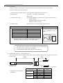
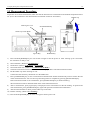
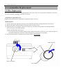
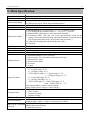
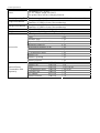
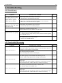
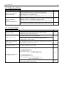
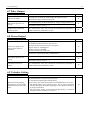
1
Light Scattering Digital Dust Monitor MODEL 3443 Operation Manual Please read this operation manual carefully and understand the warnings described within before operating this instrument. Keep this manual handy for future reference. 01001 10.06 Component List ■ Standard Item Model Qty Function Main Unit AC Adapter Filter Shoulder Strap Operation Manual Manganese Batteries Measurement Software Communication Cable LCD Protective Sheet Rubber Cap Rubber Cap String Rubber Protector 3443 6113-02 S344-30 3443-02 1 1 2 1 1 6 1 1 1 1 1 1 Spare Filter (For cleaning) Size AA batteries (for testing) CD-R USB Communication Cable Spare Sheet - ■ Optional Extras Item Model Function Output Cable Carrying Case 3442-01 3442-05 For Analog, Pulse and Alarm Output - ■ Consumables (sold separately) Item Model Unit (Qty) Rubber Cap Filter LCD Protective Sheet AC adapter Rubber Protector 3431-02 3431-03 3442-04 6113-02 3443-02 1 pc 1 Set (10 pc) 1 Set (2 pc) 1 pc 1 set Important Safety Information i Important Safety Information Warning types and classifications are defined as follows in this manual. [Classification] WARNING: To Prevent Serious Injury or Death It indicates a potentially hazardous situation which, if not avoided, may result in serious injury or death. CAUTION: To Prevent Damage to the Product It indicates a potentially hazardous situation which, if not avoided, may result in damage to the product that may void the product warranty. [Description of Symbols] △ indicates the condition (including danger) that requires caution. The subject of each caution is illustrated inside the triangle (e.g., the symbol shown on the left is high temperature caution). indicates prohibition. Do not take the prohibited action shown inside or near this symbol (e.g., the symbol shown on the left prohibits disassembly.) z indicates a mandatory action. A specific action is given near the symbol. WARNING ¤ Do not disassemble, modify or repair the instrument. …… Failure to observe the above may result in short circuit and malfunction. Do not modify/disassemble ¤ Use the instrument properly by carefully following this operation manual. …… Misuse of the instrument may result in electric shock, fire, damage to the instrument. Handle Properly ¤ If any abnormal noise, unusual odor or smoke is emitted, or any liquid enters into the instrument, turn the power off immediately, remove the battery and disconnect the power cable. …… It may result in electric shock, fire or damage to the instrument. Contact your distributor or your KANOMAX service center for repair. ¤ Do not use this instrument in an ambient temperature above 40 ˚C. …… Dielectric degradation may occur, which may result in short circuit of fire. Prohibited Installation Important Safety Information ii WARNING ¤ Unplug the power cable when the instrument is not in use. …… Failure to observe the above may result in electric shock, fire or damage to the internal circuitry. ¤ When using the AC adapter, ensure there is no dust on the power plug. The AC outlet used must be within the specified power requirement of 100 ~ 240 V. …… Failure to observe the above may result in fire. ¤ When using the AC adapter, make sure to use the one provided with this instrument. …… Other commercially available adapters may have different polarity and specifications, which could result in short circuit, fire or damage to the instrument. CAUTION ¤ Prohibited Installation Do not perform measurements in an environment exceeding the specified temperature and RH level of the instrument. Also the instrument should not be exposed to direct sunlight for prolonged periods. …… The instrument may not function properly outside the specified environment. (5 ~ 40 ˚C, 95 %RH or lower, non condensing) ¤ Do not wipe the instrument with volatile solvents. Prohibition …… The body may be deformed or deteriorated. Use soft dry cloth to remove stains. If stains persist, soak the cloth in a neutral detergent or water and wipe the instrument with the cloth. Never use volatile solvents such a thinner or benzene. ¤ Do not subject the instrument to strong shock. Do not place heavy objects on the instrument. Prohibition …… Failure to observe the above may cause damage to the instrument. ¤ Do not touch the instrument when it is or you are electrically charged. …… Failure to observe the above may affect measurement value and cause damage to the instrument circuitry. ¤ After using the instrument in the highly concentrated environment (100 CPM), make sure to perform a cleaning every time. …… Leaving the instrument without cleaning after a measurement, inside the optical system gets dirty and ZERO point may not be able to be adjusted. Cleaning Table of Contents 1. Part Names and Functions ..............................................................................1 1.1 General Outline ..................................................................................................1 1.2 Measurement Principle.......................................................................................1 1.3 Laser Handling ...................................................................................................1 1.4 Part Names .........................................................................................................2 2. Getting Started .................................................................................................4 2.1 Setting batteries or AC adapter ..........................................................................4 2.1.1 Setting batteries ....................................................................................................... 4 2.1.2 Setting AC Adapter.................................................................................................. 5 2.2 Precautions for Storing and Transporting the Instrument ..................................6 2.3 Cleaning..............................................................................................................7 2.4 Calibration ..........................................................................................................8 3. Display Description and Operation Procedure.............................................9 3.1 Boot Screen ........................................................................................................9 3.2 Initial Screen.......................................................................................................9 3.3 Screen While Measuring ..................................................................................10 3.4 MENU ..............................................................................................................12 3.4.1 Measurement Mode ............................................................................................... 12 A) Standard Mode (STD. MODE) ................................................................................. 13 B) Free Setting Mode ..................................................................................................... 15 C) Manual Mode ............................................................................................................ 15 3.4.2 Calculation Mode................................................................................................... 16 A) Measurement Start Date & Time............................................................................... 16 B) Sampling Time .......................................................................................................... 16 C) The Number of Sampling Trials................................................................................ 16 D) To Start a Measurement ............................................................................................ 16 3.4.3 Data Display .......................................................................................................... 18 3.4.4 Deleting Data ......................................................................................................... 20 A) To Delete Only the Selected Measurement Data....................................................... 20 B) To Delete All Measurement Data.............................................................................. 20 3.4.5 Calibration ............................................................................................................. 21 3.4.6 Utility..................................................................................................................... 23 A) Cleaning .................................................................................................................... 23 B) Time Adjustment....................................................................................................... 24 C) K Factor..................................................................................................................... 25 D) LCD / Beep Sound Setting ........................................................................................ 26 E) Analog Output & Alarm Setting ............................................................................... 28 F) Pulse Output .............................................................................................................. 31 G) Output Cable (3442-01) -external appearance- ......................................................... 31 H) TWA MODE ............................................................................................................. 32 3.4.7 USB Communication Connector ........................................................................... 33 3.5 Measurement Procedure ...................................................................................34 4. Consumables Replacement .......................................................................... 35 4.1 Filter Replacement ...........................................................................................35 4.2 Protective LCD Sheet Replacement .................................................................36 5. Main Specification ........................................................................................ 37 6. Troubleshooting ............................................................................................ 39 6.1 Check Power.....................................................................................................39 6.2 Check while Measuring....................................................................................39 6.3 Zero Check .......................................................................................................40 6.4 Sensitivity Check..............................................................................................40 6.5 Calibration Check.............................................................................................41 6.6 Analog Output ..................................................................................................41 6.7 Pulse Output .....................................................................................................42 6.8 Alarm Output....................................................................................................42 6.9 Calendar Setting ...............................................................................................42 7. Warranty and After-sales Service ............................................................... 43 8. Contact Information ..................................................................................... 45 1. Part Names and Functions 1 1. Part Names and Functions 1.1 General Outline This instrument (Model 3443) is a light scattering portable dust monitor using a semiconductor laser radiation light source. The measurement data is displayed on the LCD and can be saved to internal memory. The measurement data can be retrieved using the provided software. <Features> - Dimensions are reduced significantly compared to previous models - User-friendly menu. - Calibration operation can be handled from the display screen. - Data logging function allows users to redisplay saved data. - Using nonvolatile memory secures a worry-free measurement and saves measurement data and correction memory such as calibration parameters indefinitely. - USB is standard for communications. - The instrument can interface with an external device via analog output, pulse output and alarm output which are equipped standard. (The output cables are sold separately.) 1.2 Measurement Principle When dust is irradiated, the scattered light intensity from the dust is proportional to the mass concentration. Using this mechanism, this dust monitor measures the mass concentration of airborne dust. 1.3 Laser Handling Laser Classification This instrument is classified as a Class 1 Laser Product. * Class 1 Laser: Laser that is considered to be safe under reasonably foreseeable conditions of operation, including the use of optical instruments for intrabeam viewing. Laser Safety Instruction This instrument employs a laser inside the unit as the light source of the sensor. Never open/remove the case of the unit or disassemble the optical sensor inside the unit. Caution: The laser diode used inside this instrument is classified as class 3B by laser safety standard. Directly viewing or touching the laser beam is hazardous. Therefore never disassemble or modify the instrument. 1. Part Names and Functions 2 1.4 Part Names Inlet This is where sample air is taken in. A filter is built-in in order to remove coarse particles. Unit: mm Approx. 162 Sensitivity Check Knob Filter Holder Display Approx. 60 Strap Mount The shoulder strap shall be attached here. POWER Key To turn ON/OFF the power MENU Key To display the menu screen SET Key mg/m3 Key To execute the To convert the unit of the selected operation concentration between mg/m3 and and set numeric value CPM (count per minutes). START/STOP Key To start/stop measuring and cleaning ▲▼ Key To select an item and to increase / decrease numeric value Rubber Cap Approx. 73 Approx. 102 Approx. 131 Cleaning Air Vent DC-in Jack for AC Adapter USB Cable Jack Output Terminal Exhaust Port 1. Part Names and Functions 3 <Part Description> Name Function Sensitivity Check Knob This is a changeover switch to check sensitivity. When checking sensitivity, turn the knob to the “FULL” side and check if there is any significant change in the standard count value. (Refer to 2.4 Calibration) At times other than the sensitivity check, turn the knob to the “ZERO” side. To turn the knob to the “ZERO” side, press the knob and turn it to the “ZERO” side. Inlet This is where sample air is taken in. A filter is built-in to remove coarse particles. Filter Holder A filter to be used during ZERO point check and cleaning is built-in. See page 35 for the replacement procedure. Rubber Cap Strap Mount When measuring, remove it from the inlet and put it on the filter holder. When performing ZERO check, sensitivity check and cleaning, leave the rubber cap on the inlet. The shoulder strap shall be attached here. Exhaust Port This is where the air is exhausted from the internal pump. When the instrument is in use, never block the exhaust port. Cleaning Air Vent This is where air is taken in upon cleaning. When the filter is significantly dirty, replace the filter by the provided spare filter or purchase a new filter (3431-03). See page 35 for more details. Output Terminal Connect the output cable (3442-01) sold separately. - Analog Output: The voltage equivalent to 0 ~1 V is output for 0 ~ 1,000 CPM or 0 ~ 10,000 CPM. Set the load impedance to 1 kΩ or higher. The output is linear in the output range. Instantaneous value is output. - Pulse Output: The pulse equivalent to 0.0166Hz ~ 166.6 Hz is output for 1 ~ 10,000 CPM. This is photocoupler output. (no-voltage contact output) - Alarm Output: Output will be on when the value exceeds the alarm setting value. Photocoupler output is applied (no-voltage contact output). When the alarm is detected, the phototransistor will be ON. DC-in Jack for AC Make sure to use the provided AC adapter (MODEL 6113-02). Adapter USB Cable Jack Connect the provided communication cable to a PC for data download and to perform a measurement. Rubber Protector This is a protective cover for the instrument in case the instrument falls over or is hit by something. This rubber protector is also required to fix the instrument on a tripod. AC adapter, output connector and communication connector can be used even when the rubber protector is on. Tripod Screw 1/4 – 20UNC Use this screw to fix the instrument on a tripod. 2. Getting Started 4 2. Getting Started 2.1 Setting batteries or AC adapter This instrument can use batteries or AC adaptor for its power. Set batteries in the instrument or connect the AC adaptor. 2.1.1 Setting batteries 1. Slightly push the latch of the battery compartment lid in the direction of an arrow. 2. While pushing the latch, lift the lid in the direction of an arrow. Types of batteries that can be used ・ ・ ・ Manganese batteries (AA) Alkaline batteries (AA) NiMH batteries (AA) 3. Insert batteries ensuring that the battery polarity is correct. This instrument requires six (6) AA sizes batteries. Types of batteries that can be used are: Manganese, Alkaline or NiMH batteries. The six (6) batteries must be of the same type. Do NOT mix different types of batteries. Mixing different types of batteries may cause battery leakage or damage to the instrument. * Batteries CANNOT be recharged by the AC adapter. 4. Put the cover back on by reversing the above procedure. 2. Getting Started 5 2.1.2 Setting AC Adapter Connect the supplied AC adapter into the DC-in Jack on the side of the main unit. When the AC adapter is connected, the power is supplied by the AC adapter. It is OK to leave batteries in the battery compartment. However, if the instrument is not used for a prolonged time, please remove the batteries to prevent the contact failure caused by corrosion of the battery. <AC Adapter> MODEL 6113-02 INPUT: 100 ~ 240 V OUTPUT: 9V/2A Polarity DC-in Jack for AC Adapter CAUTION: Make sure to use the provided AC adapter (MODEL 6113-02). Other commercially available adapters may have different polarity and specifications, which could result in short circuit, fire or damage to the instrument. Battery Level Indicator Battery level indicator is displayed on the upper right corner of the display. The below shows how the indicator changes as the battery runs low. <<Caution>> The remaining capacity of the battery is indicated in 10 levels. When “×” is displayed on the indicator, the remaining capacity of the battery is very low. Connect the provided AC adapter immediately or finish a measurement once and replace the batteries with new ones. When the batteries die, the display will be turned off and the power will also be off. 2. Getting Started 6 2.2 Precautions for Storing and Transporting the Instrument Precautions for Storing the Instrument Caution: If the unit is not used for a prolonged time, do not leave the batteries in the battery compartment. Otherwise, the batteries may corrode, causing contact failure. Precautions for Transporting the Instrument Caution: For long periods of transporting the instrument, as mentioned above, do not leave the batteries in the battery compartment. 2. Getting Started 7 2.3 Cleaning To maintain the accuracy, make sure to perform cleaning before using the instrument. (When measuring for all day, please perform cleaning before and after measuring.) Sensitivity Check Knob MENU Key Rubber Cap START/STOP Key ▼ Key (1) Confirm that the surrounding atmosphere is clean. Put the rubber cap on the inlet as shown in the above picture and press [POWER] key to turn the power ON. (2) Confirm that the sensitivity check knob is at the “ZERO” side. (3) Press [MENU] key to display the menu. (4) Press [▼] key (or [▲] key) to move the cursor to “UTILITY” and press [SET] key to display the UTILITY screen. (5) Confirm that the cursor is on “CLEANING”, and then press [SET] key to display the CLEANING screen. (Refer to A)Cleaning in 3.4.6 Utility.) (6) Press [START/STOP] key to start cleaning. (7) Perform cleaning for about 5 minutes. * The required time for cleaning varies depending on the usage environment. (8) Press [START/STOP] key to finish cleaning. * To shorten the cleaning time as much as possible, perform a cleaning following the above procedure right after measuring and especially after measuring in a highly concentrated environment (100 CPM or higher) or after performing a long-term continuous measurement. >>> If you leave the instrument without cleaning, the remaining dust will become deposited inside the optical system, which can deteriorate the measurement accuracy and may affect accurate calibration. * Perform cleaning in a clean atmosphere. If you perform a cleaning in a dirty environment, it can cause discrepancies. Therefore, make sure to perform a cleaning in a clean environment. 2. Getting Started 8 2.4 Calibration In order to ensure accuracy you should perform a calibration before use. (When measuring all day, please perform calibration before a measurement.) For calibration there are background adjustments and sensitivity adjustments (SPAN). Rubber Cap START/STOP Key Sensitivity Check Knob MENU Key ▼ Key (1) Going to CALIBRATION Mode from MENU Key. (2) To perform an accurate calibration make sure that the instrument is acclimatized to the ambient temperature of the place where the calibration work is performed. (Leave the instrument in the environment at least for 20 minutes.) An accurate calibration cannot be performed without sufficient warm-up operation. (3) Leave the rubber cap on the inlet. (4) Turn the Sensitivity Check Knob to the “ZERO” side when adjusting BACK GROUND, and to the “FULL” side when performing SPAN CALIBRATION. (5) Press [MENU] key to display the MENU screen. (6) Press [▼] key (or [▲] key) to move the cursor to “CALIBRATION”. Then press [SET] key to display the CALIBRATION screen. (See 3.4.5 Calibration) (7) Perform the background adjustment first followed by the sensitivity adjustment. (8) After calibration is done following the above procedure, move the Sensitivity Check Knob back to the “ZERO” side. * After using the instrument under harsh conditions (high concentration) or when using the instrument frequently, be sure to perform a calibration prior to measurement. Before performing a calibration, make sure that the instrument is acclimatized to the ambient temperature. (Leave the instrument in the calibration environment for at least 20 minutes.) An accurate calibration cannot be performed without sufficient warm-up operation. * If calibration cannot be performed properly, a “CALIBRATION ERROR” will be displayed on the screen. If this is the case, start from cleaning again. ※ Calibration date is updated after “SPAN CALIBRATION”. It doesn’t track the date for “BACK GROUND” calibration. 3. Display Description and operation Procedure 9 3. Display Description and Operation Procedure 3.1 Boot Screen Press [POWER] button to turn ON the instrument. Then the boot screen will be displayed and start warming up for 10 seconds. On the screen the version information and remaining time for warming up will be displayed. 3.2 Initial Screen After the warm-up, the screen will be displayed as below. (1) (2) (3) (4) (5) (6) (7) <Operation> [START/STOP] Key: [mg/m3] Key: [MENU] Key: (8) <Display Description> (1) Date & Time (2) Remaining battery level (For details, please refer to 2.1 Setting batteries or AC adapter.) (3) Relative concentration bar(instantaneous value) (4) Indicated value (5) Unit (6) Time graph display while measuring Once a measurement starts, the bar graph will be updated. When the measurement finishes, the bar graph will disappear. In Manual Mode the graph will not be displayed. (7) Remaining measurement time Once a measurement starts, the remaining time will be displayed while the bar graph is being updated. In Manual Mode the elapsed time will be displayed. (8) Measurement mode The selected measurement mode will be displayed. Standard Mode: STD. MODE Free Setting Mode: FRE. MODE Manual Mode: MANUAL Calculation Mode: CALC. MODE To start a measurement or to halt a measurement while measuring To stop a measurement in Manual Mode To end a measurement, press and hold [START/STOP] key for approximately 2 seconds. Press this button to convert unit between “mg/m3” and “CPM”. To move to the menu screen. Refer to 3.4 MENU. 3. Display Description and operation Procedure 10 <Measurement Mode> There are four different measurement modes. You can select a measurement mode on the menu screen. Refer to 3.4.1 Measurement Mode and 3.4.2 Calculation Mode. 1) Standard Mode: Perform a measurement based on a pre-selected measurement time. You can select a measurement time from 6sec, 10sec, 30sec, 1min, 2min, 3min, 5min, 10min or TWA. 2) Free Setting Mode: Perform a measurement based on the pre-set measurement time. The settable measurement time is 1 ~ 59 sec or 1 ~ 99 min. 3) Manual Mode Manually start and stop a measurement. After starting a measurement, press [START/STOP] button to finish a measurement. 4) Calculation Mode: Repeat measuring based on the set conditions. The measurement result is saved in the memory. The conditions to be set are; - Date and time to start a measurement - Measurement time - Number of measurements To view the stored data, go to the menu screen. Refer to 3.4.3 Data Display. 3.3 Screen While Measuring During a measurement the integrated amount of particles is displayed as an indicated value, and the bar graph indicates the instantaneous value of relative concentration (CPM: Count Per Minute). The measurement time bar graph and the remaining time display indicate the remaining time of the measurement. When the bar graph display disappears, the measurement is finished. This instrument’s measurable count number is 0 ~ 999,999. If the count number exceeds this measurable range, “OVER” will be displayed on the screen. * When “OVER” is displayed on the screen, the value cannot be converted even if you press [mg/m3] button. * After measuring high concentration where “OVER” is displayed or measuring for a prolonged time, be sure to perform a cleaning to keep the inside opical system cell clean. In MANUAL Mode the elapsed time is displayed. In CALCULATION Mode, [the number of measurements performed / total number of measurements] will be displayed where the selected measurement mode is displayed in other modes. <Operation> [START/STOP] Key: [▲] [▼]Key: To stop a measurement To finish a measurement in MANUAL Mode To display a graph in CALCULATION Mode 3. Display Description and operation Procedure 11 In Calculation Mode the measurement result can be displayed successively on the graph. The vertical axis indicates CPM and the horizontal axis indicates measurement time. Up to 110 data points can be displayed. Once the number of data points exceeds 110, the graph will be scrolled so that the latest 110 data points will be displayed. When all of the measurements finish and the graph is displayed, it will go back to the initial screen automatically. <Operation> [▲] [▼] Key: [MENU] Key: To go back to the screen to display numeric value When all measurement finishes in graph display mode, press [MENU] key to go back to the screen displaying numeric values. 3. Display Description and operation Procedure 12 3.4 MENU Press [MENU] key on the initial screen to display the menu screen. On the menu screen you can select the followings; MODE: Measurement Mode To set a measurement mode => 3.4.1 Measurement Mode CALCULATION: Calculation Mode To set calculation mode and to start a measurement => 3.4.2 Calculation Mode DATA DISPLAY To display measurement data saved in the memory of the instrument on the screen => 3.4.3 Data Display DATA CLEAR To delete measurement data saved in the memory of the instrument => 3.4.4 Deleting Data CALIBRATION To perform background adjustment and sensitivity adjustment => 3.4.5 Calibration UTILITY To perform cleaning and calibration and to configure each setting => 3.4.6 Utility <Operation> [MENU] Key: [▲][▼] Key: [SET] Key: To go back to the initial screen To move the cursor up and down To display the screen that is indicated by the cursor 3.4.1 Measurement Mode Select “MODE” on the menu screen to display the screen shown on the left. On this screen, select one measurement mode out of three options. The options are; STD. SET: Standard Mode FREE SET: Free Setting Mode MANUAL: Manual Mode Move the cursor up and down by using [▲] [▼] keys, and select the item by pressing [SET] key. * Please note that unless you press [SET] key when [SAVE INFO] is pointed at by [►] on the setting screen of the each mode, setting will not be saved. 3. Display Description and operation Procedure 13 A) Standard Mode (STD. MODE) In the Standard Mode select the time from the pre-set measurement time. The selectable measurement time is 6 sec, 10 sec, 30 sec, 1 min, 2 min, 3 min, 5 min 10 min or TWA (Time Weighted Average) mode. While the measurement time is highlighted, you can change the time by using [▲] [▼] keys. Measurement Time Transition 06sec [▲] Key ↓ ↑ [▼] Key 10sec [▲] Key ↓ ↑ [▼] Key 30sec [▲] Key ↓ ↑ [▼] Key Move the cursor to STD. SET, and then press [SET] key to highlight the measurement time to configure the setting. Once a measurement time is selected, press [SET] key. The measurement time will stop being highlighted. Use [▲] [▼] keys to move the cursor to “SAVE INFO”, and press [SET] key to save the setting. Then a measurement screen will be displayed To go back to a measurement screen before you complete the setting, press [MENU] key. 01min [▲] Key ↓ ↑ [▼] Key 02min [▲] Key ↓ ↑ [▼] Key 03min [▲] Key ↓ ↑ [▼] Key 05min [▲] Key ↓ ↑ [▼] Key 10min [▲] Key ↓ ↑ [▼] Key 06sec mg/m3 (Instantaneous Value) <6 sec, 10 sec, 30 sec, 1 min, 2 min, 3 min, 5 min 10 min or TWA mode> A measurement is performed for the set measurement time. Press [START/STOP] key to start a measurement. After a measurement finishes, the measurement result will be displayed. The remaining measurement time will be indicated at the lower left and also indicated in the bar graph below the measurement value. You can stop a measurement before it completes by pressing and holding [START/STOP] key for about 2 seconds. 3. Display Description and operation Procedure 14 You can switch over the indicated value as described below by pressing [mg/m3] key in real time. Switching over measurement value mg/m3 (Instantaneous Value) Mg/m3 [mg/m3] key ↓ CPM (COUNT) [mg/m3] key ↓ mg/m3 (Instantaneous Value) CPM(COUNT) mg/m3 (Instantaneous Value) <TWA Mode> In TWA mode you can perform a measurement based on the settings referring to H) TWA MODE in 3.4.6 Utility. Press [START/STOP] key to start a measurement. After a measurement completes, the measurement result will be displayed. The remaining measurement time is indicated on the bottom of the screen and also shown in the bar graph. You can forcibly finish a measurement by pressing and holding [START/STOP] key for about two seconds. In TWA mode you can switch over the indicated value as described below by pressing [mg/m3] key during and after a measurement. mg/m3 (T) Switching over measurement value mg/m3 (Instantaneous Value) [mg/m3] key ↓ mg/m3 (TWA) [mg/m3] key ↓ mg/m3 (STEL) mg/m3 (S) [mg/m3] key ↓ mg/m3 (C) [mg/m3] key ↓ CPM (COUNT) [mg/m3] key ↓ mg/m3 (C) CPM(COUNT)01min mg/m3 (Instantaneous Value) 3. Display Description and operation Procedure 15 B) Free Setting Mode In Free Setting Mode you can set the measurement time in the range of 1~59 sec in increments of one second or in the range of 1 ~ 99 minutes in increments of one minute. While a measurement time is highlighted, you can change it by using [▲] [▼] keys. Measurement Time Transition 01sec Press [▲] key to increase 1 sec ↓ ↑ Press [▼] key to decrease 1 sec 01min Press [▲] key to increase 1 min ↓ ↑ Press [▼] key to decrease 1 min 99min Move the cursor to “FREE SET”, and then press [SET] key to highlight the measurement time to configure the setting. Once a measurement time is set, press [SET] key. The measurement time will stop being highlighted. Use [▲] [▼] keys to move the cursor to “SAVE INFO” and press [SET] key to save the setting. Once the setting is saved, it will go back to the measurement screen. To go back to the measurement screen before you complete the setting, press [MENU] key. C) Manual Mode In Manual Mode you can finish a measurement any time by pressing [START/STOP] key. When YES/NO is highlighted, you can select to measure in the Manual Mode or NOT by using [▲] [▼] keys. To perform a measurement in Manual Mode, select YES in the setting. Move the cursor to “MANUAL” and press [SET] key to highlight it to configure the setting. After selecting YES or NO, press [SET] key. The selected item will stop being highlighted. Move the cursor to “SAVE INFO” by using [▲] [▼] keys, and then press [SET] key to save the settings. Then it will go back to the menu screen. To go back to the measurement screen before you complete the setting, press [MENU] key. 3. Display Description and operation Procedure 16 3.4.2 Calculation Mode Select “CALCULATION” mode on the menu screen to display the screen shown on the left. In the CALCULATION MODE you can set date & time to start a measurement, sampling time and number of sampling trials. Use [▲] [▼] keys to move the cursor to the item to be set. Then press [SET] key to configure each setting. START DATE/TIME: Date & time to start a measurement SAMPLING TIME: Sampling time (1 sec ~ 99 min 59 sec) No. TRIAL (N): No. of sampling trials (1 ~ 30,000 times) SET TO START: To start a measurement To go back to the menu screen before you complete the setting, press [MENU] key. A) Measurement Start Date & Time Set each figure in the order of Year→Month→Date→Hour→Min→Sec if JP is selected for date mode. (Refer to 3.4.6 Utility B)Time Adjustment) Use [▲] key to increase the value of the highlighted item and [▼] key to decrease the value. Press [SET] key to move the cursor to the next item. After setting the second, the date and time will stop being highlighted, and now you can select the next item to be configured. B) Sampling Time Set sampling time. Use [▲] key to increase the value of the highlighted item and [▼] key to decrease the value. The settable range is 1 sec ~ 99 min 59 sec. After setting the sampling time, press [SET] key. Then the time will stop being highlighted, and now you can select the next item to be configured. C) The Number of Sampling Trials The number of sampling trials will be highlighted. Use [▲] to increase the value and [▼] key to decrease. The settable measurement cycle is up to 30,000 times. Press [SET] key to complete setting. The set value will stop being highlighted, and now you can select the next item to be configured. D) To Start a Measurement Press [SET] key to go back to the initial screen and the instrument will start stand-by for starting a measurement. When the configured date and time comes, a measurement will start. 3. Display Description and operation Procedure 17 <Stand-by Screen> Press [SET] key to start stand-by for a measurement. When the configured date and time comes, a measurement will start. User also starts measurement manually by pushing START/STOP Key. CALCILATOIN Mode shows the error message when the data storage is full. Make available space after deleting some data, and select CALCULATION Mode. (See 3.4.4 for Deleting Data) <Screen While Measuring> During a measurement use [▲] [▼] keys to change the numerical display to graph display. Press the key again to go back to the numerical display. Measurement stops and shows “REC: FULL” when the data storage gets full. Measurements are saved until the point. <Graph Display> During a measurement use [▲] [▼] keys to change the graph display to count value display. Press the key again to display the graph. Unit used in vertical axis: mg/m3 Unit used in vertical axis: CPM The unit selected on the numerical display applies to the vertical axis. The range changes as the measurement value increases in three steps. * mg/m3 0-0.1mg/m3 range 0-1mg/m3 range 0-10mg/m3 * CPM 0-100CPM range (10^2) 0-1000CPM range (10^3) 0-10000CPM range (10^4) 3. Display Description and operation Procedure 18 After a measurement, use [▲] [▼] keys to scroll the graph display. The number of data points that can be displayed in one screen is 110. To switch the graph display to the count display after a measurement, press [MENU] key. Press [MENU] key 3.4.3 Data Display <data list display screen> Select DATA DISPLAY on the menu screen to display the data list display screen shown on the left. A list of data points taken in the CALCULATION MODE will be displayed. Use [▲] [▼] keys to move the cursor to the data point you want to display, and press [SET] key to select it. Press [MENU] key to go back to the menu screen. The calculation result of the selected data point is displayed. TIME: Measurement time (MM:SS) K: K Factor CYCLES: Number of measurement cycles MAX: Maximum concentration MIN: Minimum concentration AVE: Average concentration Press [SET] key to display a list of each measurement data. Press [MENU] key to go back to the previous screen. Each measurement data will be displayed. A measurement data is displayed in one line in the order of the measurement time and concentration (unit: CPM). Press [▲] [▼] keys to scroll the screen. Press [SET] key to display a graph. Press [MENU] key to go back to the data list display screen. 3. Display Description and operation Procedure 19 Time-line graph of the measurement data will be displayed. Up to 110 data points can be displayed on one screen. The unit selected on the numerical display applies to the vertical axis. The range changes as the measurement value increases in three steps. * mg/m3 0-0.1mg/m3 range 0-1mg/m3 range 0-10mg/m3 * CPM 0-100CPM range (10^2) 0-1000CPM range (10^3) 0-10000CPM range (10^4) Press [▲] [▼] keys to scroll the screen. Press [MENU] key to go back to the data list display screen. 3. Display Description and operation Procedure 20 3.4.4 Deleting Data Select DATA CLEAR on the menu screen to display the screen shown on the left. You can select to delete either only the selected data or all measurement data. Press [▲] [▼] keys to move the cursor and press [SET] key to select the item. Press [MENU] key to go back to the menu screen. A) To Delete Only the Selected Measurement Data Set the first and the last measurement data numbers to be deleted. The item to be set will be highlighted. Press [▲] key to increase the figure and [▼] key to decrease the figure. Press [SET] key to fix the value. The set value will stop being highlighted. After setting the data number, YES/NO for SET will be highlighted. To perform deletion, select [YES] using [▲] [▼] keys and then press [SET] key. Then the data in the selected range will start to be deleted. When the data deletion completes, the display will go back to the DATA CLEAR screen where you can select to delete only selected data or all data. “DATA Cleared” will appear after deleting data. To go back to the MENU screen, press [MENU] key. B) To Delete All Measurement Data YES/NO will be highlighted. To perform deletion, select [YES] using [▲] [▼] keys and then press [SET] key. Then all of the data will start to be deleted. When the data deletion completes, the display will go back to the DATA CLEAR screen where you can select to delete only selected data or all data. “DATA Cleared” will appear after deleting data. To go back to the MENU screen, press [MENU] key. 3. Display Description and operation Procedure 21 3.4.5 Calibration To perform an accurate calibration make sure that the instrument is acclimatized to the ambient temperature of the place where the calibration work is performed. (Leave the instrument for at least 20 minutes.) An accurate calibration cannot be performed without sufficient warm-up operation To calibrate the instrument → Refer to 2.4 Calibration. Before starting calibration, perform cleaning. Leave the rubber cap on the inlet. Move the sensitivity check knob to the “ZERO” side. Perform the background adjustment first followed by the sensitivity adjustment. Press [▲] [▼] keys to move the cursor to the item to be set, and then press [SET] key to configure the setting. BACK GROUND: Background Adjustment SPAN CALIBRATION: Sensitivity Adjustment To go back to the MENU screen before completing the setting, press [MENU] key. <Background Adjustment> To perform the background adjustment Press [START/STOP] key to start a measurement. [START/STOP] Key A measurement will be performed for 6 seconds. During a measurement the instantaneous value of the background (CPM) will be displayed. The remaining measurement time will be displayed on the bottom of the display. The measurement will finish in 6 sec. When a measurement is finished, the average background value (CPM) at the time will be displayed. To perform the background adjustment with this value, select SET. If not, select CANCEL. Press [▲] [▼] keys to move the cursor, and press [SET] key to configure the setting. After the adjusted value is displayed for about 2 seconds, the unit will go back to the CALIBRATION screen. 3. Display Description and operation Procedure 22 <Sensitivity Adjustment (SPAN)> To perform sensitivity adjustment Before performing a sensitivity adjustment, be sure to do the background adjustment. After background adjustment, turn the sensitivity knob to the “FULL” side. The date of the last sensitivity adjustment and standard count value are displayed. Press [START/STOP] key to start a measurement. [START/STOP] Key A measurement will be performed for 6 seconds. During a measurement the instantaneous value of the standard count (CPM) will be displayed. The remaining measurement time will be displayed on the bottom of the display. The measurement will finish in 6 sec. The standard count value (CPM) at the time is displayed on the screen. To perform Sensitivity Check with this value, select SET. If not, select CANCEL. Press [▲] [▼] keys to move the cursor, and press [SET] key to configure the setting. After the adjusted value is displayed for about 2 seconds, the display will go back to the CALIBRATION screen. *Calibration date is updated after “SPAN CALIBRATION”. It doesn’t track the date for “BACK GROUND” calibration. * To perform an accurate calibration make sure the instrument is acclimatized to the ambient temperature of the place where the calibration work is performed. (Leave the instrument at least for 20 minutes.) An accurate calibration cannot be performed without sufficient warm-up operation. * Background Adjustment Performing Background Adjustments in a highly concentrated environment or making an operation error will influence a measurement value significantly. Therefore, please pay attention when performing a background adjustment. When the background adjustment value differs from the manufacturer’s calibrated value by ±20 counts, it is considered as an error and the adjustment value cannot be stored. If that is the case, please contact your sales representative or KANOMAX service center. * Sensitivity Adjustment Just as the Background Adjustment, performing Sensitivity Adjustment in the highly concentrated environment or making an operation error will influence a measurement value significantly. Therefore, please pay attention when performing a background adjustment. When the sensitivity adjustment range differs from the manufacturer’s calibrated range by more than ±20%, the adjustment value cannot be stored. If that is the case, please contact your sales representative or KANOMAX service center. 3. Display Description and operation Procedure 23 3.4.6 Utility Select UTILITY on the menu screen to display the screen shown on the left. In UTILITY you can perform preparation for a measurement and configure settings. Press [▲] [▼] keys to move the cursor to the item to be set, and then press [SET] key to configure the setting. CLEANING TIME ADJUST: Time Setting K FACTOR: The Mass Concentration Conversion Coefficient setting LCD/BEEP: LCD & Beep Sound setting ANALOG OUT/ALARM: Analog Output & Alarm setting TWA MODE: TWA Measurement Mode Setting To go back to the MENU screen, press [MENU] key. A) Cleaning To clean the instrument → Refer to 2.3 Cleaning. To start cleaning, put the rubber cap on the inlet. Confirm that the sensitivity check knob is at the “ZERO” side. Press [START/STOP] key to start cleaning. Press [MENU] key to go back to the UTILITY screen. [START/STOP] Key Push “START/STOP” Key to stop cleaning. Push MENU Key to go back to UTILITY Menu. Perform cleaning for approximately 5 minutes. * Required cleaning time is different depending on the use environment. * If an error occurs during calibration and background adjustment after cleaning for more than 10 minutes, the internal cleaning is required. Please contact your distributor or KANOMAX service center. 3. Display Description and operation Procedure 24 B) Time Adjustment To configure the date format and time setting STYLE: Date Format Selection DATE: Date Setting TIME: Time Setting Press [▲] [▼] keys to move the cursor, and press [SET] key to select it. Press [MENU] key to go back to the UTILITY screen. <Date Format Selection> For the date format select one among JP, US or EU. Each format is as follows; JP: YYYY/MM/DD US: MM/DD/YYYY EU: DD/MM/YYYY YYYY: Year, MM: Month, DD: Date JP/US/EU will be highlighted. Press [▲] [▼] keys to change the setting. Press [SET] key to fix the setting and the set item will stop being highlighted. The display will go back to the screen where you can select the item to be configured. To go back to the UTILITY screen, press [MENU] key. <Date Setting> Configure the value in the order of Year → Month → Date. (This is in case of selecting JP for the data display format. The setting order differs depending on the data display format.) Use [▲] key to increase the figure of the highlighted item and [▼] key to decrease it. Use [SET] key to highlight the next item. Once the date setting is complete, all items will stop being highlighted and the display will go back to the screen where you can select the item to be configured. <Time Setting> Configure the value in the order of Hour → Minute → Second. Use [▲] key to increase the figure of the highlighted item and [▼] key to decrease it. Use [SET] key to highlight the next item. After setting second, the time will stop being highlighted, and the display will go back to the screen where you can select the item to be configured. <To Store the Setting> Press [SET] key to store the setting and go back to the UTILITY screen. 3. Display Description and operation Procedure 25 C) K Factor Set the factor of Mass Concentration Conversion Coefficient (K FACTOR). Move the cursor to K FACTOR and press [SET] key to highlight the value. Press [▲] key to increase by 0.0001 and [▼] key to decrease by 0.0001. The range of the settable factor is 0.0001 ~ 0.0099. Select a value for K FACTOR, and then press [SET] key. The factor will stop being highlighted. Use [▲] [▼] keys to move the cursor to SAVE INFO, and then press [SET] key to store the setting and go back to the UTILITY screen. To stop configuring the setting and go back to the UTILITY screen, press [MENU] key. * The settable factor range is K = 0.0001 ~ 0.0099. * Before shipping, 1 CPM = 0.0010 mg/m3 is assigned for calibration particle. Therefore, K factor is set to 0.0010. * Example: K = 0.0010: 100 CPM → 0.1 mg/m3 K = 0.0020: 100 CPM → 0.2 mg/m3 To convert the value indicated by the instrument into the mass concentration (mg/m3) the Mass Concentration Conversion Coefficient (K factor) shall be obtained. The K-factor is determined by performing a parallel measurement based on a filtration instrument which uses particle size analyzer. How to obtain K-factor is as follows: Prepare the instrument (Model 3443) and a filtration instrument which uses a particle size analyzer. When placing these two units, keep their suction direction and the height of the suction points same. Select “MANUAL” mode on the instrument and start measuring using those units at the same time. To calculate K-factor, divide the mass concentration (C) measured by the filtration instrument by the count per minute (R). In order to obtain (R) divide the count you get using this instrument by the measurement time (min). K = C/R To convert the factor into mass concentration (mg/m3), multiply the K-factor by CPM that you obtain at each measurement point using this instrument. * The ranges of corresponding value of mass concentration are 0 to 10,000 counts. The counts above the range won’t be converted accurately. 3. Display Description and operation Procedure 26 D) LCD / Beep Sound Setting You can set the screen contrast, the backlight-out time and to turn ON/ OFF the beep sound. CONTRAST: To set contrast of the display BACKLIGHT OFF: To set the backlight-out time BEEP: To turn ON/OFF beep sound Press [▲] [▼] keys to move the cursor, and then press [SET] key to select it. Press [MENU] key to go back to the UTILITY screen. <Contrast of the display> The numeric value for the screen contrast will be highlighted. Press [▲] key to increase the value by 1 and [▼] key to decrease the value by 1. The range of the contrast is 20 ~ 54. After setting the value, press [SET] key. Then the value will stop being highlighted, and now you can select the next item to be configured. <Backlight-Off Time> For battery saving purpose, set the time to activate the automatic backlight OFF function when the instrument is not in operation. The automatic backlight OFF time will be highlighted. Press [▲] key to increase the numeric figure and press [▼] key to decrease the figure. The settable range for backlight OFF time is 1 ~ 99 min or you can set to turn ON the backlight all the time. After setting the value, press [SET] key. Then the value will stop being highlighted, and now you can select the next item to be configured. Press [▼] key when the value is 1 to select “Always ON” setting to turn the backlight ON all the time. To select “Always ON”, you can also press [▲] key when the value of 99 is selected. After 1 min [▲] key to increase by 1 min ↓ ↑ [▼] key to decrease by 1 min After 99 mins [▲] key ↓ ↑ [▼] key キー Always ON 3. Display Description and operation Procedure 27 <Beep Sound Setting (On/OFF)> You can set whether to activate the beep ON or OFF for key operation. When ON/OFF setting is highlighted, you can change the setting by using [▲] [▼] keys. After setting, press [SET] key. The setting will stop being highlighted, and now you can select the next item to be configured. <Saving the settings> Press [SET] key to save the settings and go back to the UTILITY screen. 3. Display Description and operation Procedure E) 28 Analog Output & Alarm Setting Set the analog output and alarm range. ANALOG OUT: Analog Output Setting ALARM: Alarm ON/OFF Setting Press [▲] [▼] keys to move the cursor and select the item pressing [SET] key. Press [MENU] key to go back to the UTILITY screen. <Analog Output Setting> Set the relation between the measured concentration value (mg/m3) / measured relative concentration value (CPM) and the voltage output from the output terminal. The concentration range which corresponds to the output of 0 ~ 1 V will be highlighted. 0-1 mg/m3: When the concentration is 1mg/m3, 1V is output. 0-10 mg/m3: When the concentration is 10mg/m3, 1V is output. AUTO mg/m3: The output voltage will be switched over automatically; When the concentration is 0~1mg/m3, 0~1V is output. When the concentration is 1~10mg/m3, 0.1~1V is output. 0-1,000 CPM: When the concentration is 1,000 CPM, 1V is output. 0-10,000 CPM: When the concentration is 10,000 CPM, 1V is output. AUTO CPM: The output voltage will be switched over automatically; When the concentration is 0 ~ 1,000 CPM, 0 ~ 1V is output. When the concentration is 1,000~10,000 CPM, 0.1~1V is output. Use [▲] [▼] keys to change the setting. 0-1 mg/m3 [▲] Key↓ ↑ [▼] Key 0-10 mg/m3 [▲] Key↓ ↑ [▼] Key AUTO mg/m3 [▲] Key↓ ↑ [▼] Key 0-1000 CPM [▲] Key↓ ↑ [▼] Key 0-10000 CPM [▲] Key↓ ↑ [▼] Key AUTO CPM After setting the value, press [SET] key. The setting will stop being highlighted and the screen will go back to the display where you can select the item to be configured. 3. Display Description and operation Procedure 29 (1) Data Update Interval: The output data is output every one second. (2) Load Impedance: 1 KΩ or higher (3) Output Cable: Please purchase our optional output cable (3442-01). Method to output measurement data (in case of analog output) Explanation Voltage Concentration value (mg/m3 or CPM) will be converted to the output voltage. 0 1 2 3 4 sec(Measurement Time) * Use the dedicated output cable (3442-01) sold separately. <Alarm Setting> When the reading exceeds the set concentration value during a measurement, the alarm will be turned ON. And when the reading becomes lower than the set concentration value, the alarm will be OFF. This alarm will be activated only during a measurement. (Even if the alarm is ON during a measurement, it will be OFF once the measurement finishes.) When alarm mode setting is OFF, the alarm function is not activated. Use [▲] [▼] keys to change the mode setting. mg/m3 [▲] key to CPM setting ↓ ↑ [▼] key to mg/m3setting CPM [▲] key to OFF setting ↓ ↑ [▼] key to CPM setting OFF After setting the alarm mode, press [SET] key. The RANGE setting value will be highlighted. Use [▲] [▼] keys to set the value. After setting, press [SET] key. Then the RANGE setting value will stop being highlighted. 10.000 [▼] key to decrease ↓ ↑ [▲] key to increase 9.999 3. Display Description and operation Procedure 30 The range setting is also required in CPM mode as well. 10000 [▼] key to decrease ↓ ↑ [▲] key to increase 9999 Use [▲][▼] keys to move the cursor and select [SAVE INFO]. Then press [SET] key. The set value will be saved and the screen will go back to the UTILITY screen. “AlarmOver” will appear when measurement hits over the range (1) Data Update Interval: The output data is updated every one second. (2) Effective Range of the Output: From when a measurement starts until the measurement finishes. (3) Output Format, Spec: Photocoupler Output (no-voltage contact output: collector emitter) Model: TLP127 Maximum Applied Voltage: DC300V Maximum Current: 150mA (4) Output Cable: Please use the optional analog / alarm output cable (3442-01). Alarm Output Explanation 3 CPM(mg/m ) ON Alarm Setting OF Alarm is activated based on the value of concentration (mg/m3 or CPM). (Output Terminal Circuit) Finish + output 1 2 n n+1 n+2 n+3 n+4 n+5 n+6(Measurement Time) Start * Use the dedicated output cable (3442-01) sold separately. − 3. Display Description and operation Procedure F) 31 Pulse Output With this instrument the pulse that corresponds to CPM value (instantaneous value) can be output. Connect the output cable sold separately. (1) Pulse Frequency Update Interval: The output data is updated every one second. (2) Pulse Range: 0.0166 Hz – 166.6 Hz (1-10,000 CPM) DUTY 50% (3) Output Format, Spec: Photocoupler Output (no-voltage contact output: collector emitter) Model: TLP127 Maximum Applied Voltage: DC300V Maximum Current: 150mA (4) Output Cable: Please purchase our optional output cable (3442-01). Pulse Output CPM (Instantaneous Value) 1 CPM 60 CPM 600 CPM 6,000 CPM 10,000 CPM Explanation The pulse equivalent to the CPM value (instantaneous value) is output. Pulse Frequency 0.0166 Hz 1 Hz 10 Hz 100 Hz 166.6 Hz (Output Terminal Circuit) + output * The pulse output is more than 1 CPM and the resolution is 1 CPM. When CPM is 0 CPM, there is no pulse output. − * The CPM value (instantaneous value) used for pulse output differs from the COUNT value on the LCD display. * Use the dedicated output cable (3442-01) sold separately. G) Output Cable (3442-01) -external appearanceThis is the dedicated cable for analog output, pulse output and alarm output. This is an option at the time of Cable 2 Cable 1 purchase only. 1000 mm 150 mm Connector at the dust monitor side Relay Connector Bare crimping terminal – Y type (forM3) Signal Name * Supplied as a set of cable 1 and cable 2. Analog Output Alarm Output Pulse Output Sig GND + − + − Wiring Color ‐ Cable 2 Red Black White Blue Yellow Green Marking ANALOG + ANALOG − ALARM + ALARM − PULSE + PULSE − 3. Display Description and operation Procedure 32 H) TWA MODE If you select TWA on the menu screen, the screen shown on the left will be displayed. You can configure TWA measurement setting and alarm setting. TWA TIME (m): TWA VALUE: STEL VALUE: C VALUE: ALARM SET: SAVE INFO: Measurement time setting (1 min ~ 48 hrs, settable by minutes) Time-weighted average (0.001 ~ 10.000, STEL>TWA) Short-term exposure limit (0.001 ~ 10.000, C>STEL>TWA) Upper limit tolerance (0.001 ~ 10.000, C>STEL) Alarm ON/OFF setting Save settings Use [▲][▼] keys to move the cursor and press [SET] key to set it. Press [MENU] key to go back to the UTILITY screen. If an error is detected in the settings for TWA VALUE, STEL VALUE, C VALUE, [ERROR!] will be indicated on the lower right of the screen for two seconds. <Time-weighted average (TWA)> Input Range: The short term exposure limit (STEL) or less in the range of [0.001-10.000] mg/m3 Time-weighted average (TWA) is the time-weighted average concentration for the regular working hours of 8 hours a day and 40 hours a week. When the average concentration (mg/m3) from the beginning to the ending of the TWA mode measurement exceeds this set value, an alarm will be activated. The TWA measurement value is displayed in real time. If the measurement time is less than 8 hours, the time length till the end of the measurement is subject to this measurement. <Short term exposure limit (STEL)> Input Range: Between the time-weighted average (TWA) and the upper limit tolerance (C) in the range of [0.001-10.000] mg/m3 If the latest moving average concentration (mg/m3) for 15 minutes exceeds this setting value, an alarm will be activated. The short term exposure limit (STEL) is displayed in real time. The alarm will also be activated if the concentration exceeds the time-weighted average (TWA) 5 times or more within 8 hours or the concentration exceeds TWA twice or more within 60 minutes. If the measurement time is less than 8 hours, the time length till the end of the measurement is subject to this measurement. <Upper limit tolerance (C)> Input Range: The short-term exposure limit (STEL) or less in [0.001-10.000]mg/m3 If the instantaneous concentration (one sampling) (mg/m3) exceeds this set value, an alarm will be indicated. The upper limit tolerance (C) is displayed in real time. 3. Display Description and operation Procedure 33 <Alarm Classification> The alarm sound will be different depending on the content of an alarm. The alarm in the TWA measurement mode will be indicated on the measurement screen and beep will sound. Please note that it will not output to the external output terminal. Time-weighted average (TWA) alarm Short beeps Short-term exposure limit (STEL) alarm Long beeps Upper limit tolerance (C) alarm Continuous beep * Upper limit tolerance alarm is given the highest priority followed by short-term exposure limit (STEL) alarm and then time-weighted average (TWA) alarm. For example, if the upper limit tolerance (C) alarm occurs during the Short-term exposure limit (STEL) alarm, the upper limit tolerance (C) alarm will be prioritized. <Clear Alarm> When alarm occurs, press [▲] or [▼] key to clear alarm. If another alarm condition is detected right after an alarm is cleared, alarm will output. An alarm can only be cleared individually. If you do not clear an alarm during a measurement, the alarm will keep outputting until you clear an alarm. An alarm can only be cleared by the user clearing an alarm or starting a next measurement. 3.4.7 USB Communication Connector By connecting the provided USB cable, you can communicate with a computer. (1) Use the provided USB communication cable. (2) Install the provided measurement software in your computer. (3) For details on the measurement software including the installation procedure, please refer to the operation manual for Measurement Software for Light Scattering Digital Dust Monitor (Model S344-20). 3. Display Description and operation Procedure 34 3.5 Measurement Procedure To perform an accurate measurement, make sure that the instrument is acclimatized to the ambient temperature before use. (Leave the instrument in the measurement environment at least for 20 minutes.) Rubber Cap Cleaning Air Vent 6) START/STOP Key Sensitivity Check Knob mg/m3 Key 1) POWER Key Press and hold [POWER] key for one second or longer to turn the power on. After warning up for 10 seconds, the instrument is ready to run. 2) Start calibration. (Refer to 2.4 Calibration.) 3) Set K factor. (Refer to (c) K Factor in 3.4.6 Utility.) 4) Set measurement time. (Refer to 3.4.1 Measurement Mode.) 5) Check the measurement time at the lower left of the display and the selected measurement mode. 6) Put the rubber cap on the cleaning air vent. Confirm that the sensitivity check knob is at the ZERO side. 7) Press [START/STOP] key to start a measurement. Measurement finishes automatically when it reaches the end of the measurement time. You can also stop measuring before it completes by pressing [START/STOP] key. If the measurement mode is set to MANUAL, press [START/STOP] key to finish measuring. The measurement result is obtained based on the actual measurement time. 8) After a measurement, press [mg/m3] key to display the mass concentration to take the reading. To perform the next measurement, press [START/STOP] key again and repeat the instruction described above. 9) After all measurements are done, put the rubber cap on the inlet. 10) Perform cleaning. (Refer to 2.3 Cleaning.) 11) Press and hold [POWER] key for 2 sec or longer to turn the power off. 4. Consumables Replacement 35 4. Consumables Replacement 4.1 Filter Replacement Please replace the filter following the procedure below when error occurs even if you perform calibration several time, you can see the filter is damaged or the filter is very dirty. <Preparing for replacement part> Prepare the provided filter for replacement or purchase the filter (3431-03). <Replacing filter> (1) Turn the filter fixing ring on the cleaning air port to the direction shown in the picture below and remove it. (2) Remove the rubber packing and filter in the filter holder by using tweezers. (3) Prepare the filter for replacement. Then put it all the way in the holder being careful not to damage the filter. Next set the filter on the rubber packing. Finally tighten the filter fixing ring on. * If you forget to place the rubber packing or fail to tighten the lid fully, leaking may occur which will prevent an accurate measurement. Therefore, when replacing parts, be sure not to lose anything. (4) After replacing the filter, start performing cleaning. (Refer to 2.3 Cleaning) Rubber Packing Filter (2) ZOOM (1) Filter Fixing Ring Filter Holder 4. Consumables Replacement 36 4.2 Protective LCD Sheet Replacement When the protective LCD sheet becomes dirty or is damaged, replace it. <Preparing for replacement part> Prepare the provided protective LCD sheet for replacement or purchase the provided protective LCD sheet (3442-04). <Replacing protective LCD sheet> (1) Remove the protective sheet that is to be replaced. (2) Wipe out the dirt and dust on and around the LCD. (3) Put the new protective sheet for replacement on the LCD. 4.3. Rubber Protector Replacement When the rubber protector becomes dirty or is damaged, you can replace the rubber protector. <Preparing for replacement part> Purchase the rubber protector (3442-02). <Replacing rubber protector> (1) Remove the AC adapter and output cable. (2) Pull the instrument up to remove it from the rubber protector. (3) Insert the instrument into the new rubber protector. For the insertion direction, refer to the picture below. Make sure that the top corners of the rubber protector are fit with the instrument. (2) Pull the instrument out from the protective cover. (3) Insert the instrument into the new protective cover. Make sure that the cleaning air vent side of the instrument and the logo on the rubber protector are facing the same direction. 5. Main Specification 37 5. Main Specification Product Name Model Name Light Scattering Digital Dust Monitor MODEL 3443 0.001 ~ 10.000 mg/m3 Measurement Range (1 CPM=0.001 mg/m3 when using standard particle) Measurement Accuracy ±(10% of reading + 1) count Linearity ±5% of reading (1) Standard Mode (6, 10, 30 seconds, 1, 2, 3, 5, 10 minutes, TWA) (2) Free Setting Mode (Settable range is 1 ~ 59 sec or 1 ~ 99 min) (3) Manual Mode (Start and stop a measurement manually.) (4) Calculation Mode (The user can repeat measurements based on the Measurement Mode settings of measurement start/stop time and the number of measurements. The measurement data can be saved in the built-in memory.) (5) Calibration (background and standard count value) (6) Cleaning Light Source Semiconductor Laser Diode Detector System Photodiode Measuring Method Light Scattering Display Graphic LCD (128×64 dot) with backlight (1) Remaining Battery Level (10 levels) (2) Measurement Time (Remaining Measurement Time) (3) Measurement Value Displayed Items (4) Measurement Mode (5) K Factor (6) Graph Analog Output (The output range setting can be switched over.) - 0 – 1 mg/m3 range: 0-1V - 0 – 10 mg/m3 range: 0-1V - AUTO mg/m3 range: 0 – 1 mg/m3 range: 0-1V 1 – 10 mg/m3 range: 0.1-1V - 0 – 1,000 CPM range: 0-1 V Output Terminal - 0 – 10,000 CPM range: 0-1 V - AUTO CPM range: 0 – 1,000 CPM range: 0-1 V 1,000 – 10,000 CPM: 0.1 – 1 V Pulse Output (Photo-coupler Contact Output) Alarm Output (Photo-coupler Contact Output) USB Port - Data Transfer Communication - Parameter Setting - Remote Setting Calibration Function Auto Background Factor of Mass Concentration Settable on operation panel Conversion Coefficient (Settable range: 0.0001 ~ 0.0099, in increments of 0.0001) Up to 100,000 data points can be saved. Data log & Calculation Data Readout, Data Display Function Calculation Function 5. Main Specification AA batteries (1.5 × 6 pcs) AC: AC adapter (Input 100-240 V) The product does not have charging function. Battery Operating Time Continuous operation time: 12 hours (when alkaline batteries are used.) Temperature: 5 ~ 40 ˚C Usage Environment Humidity: 95 %RH or lower (Non condensing) Temperature 0 ~ 45 ˚C Storage Environment Humidity: 95 %RH or lower (Non condensing) Dimensions 162 × 60 × 102 mm (excluding projections) Weight Approximately 1.1 kg (excluding batteries) AC Adapter 1 pc Filter 2 pc Shoulder Strap 1 pc Operation Manual (Main Unit) 1 pc Manganese Batteries 6 pc Measurement Software (CD) 1 pc Accessories Communication Cable 1 pc LCD Protective Sheet 1 pc Rubber Cap 1 pc Rubber Cap String 1 pc Rubber Protector 1 pc For analog, pulse & alarm output Output Cable (3442-01) Rubber Cap (3431-02) 1 pc Filter (3431-03) 1 set (10 pc) Optional Extras, LCD Protective Sheet (3442-04) 1 set (2 pc) Consumables Sold Carrying Case (3442-05) 1 pc Separately 1 pc AC Adapter (6113-02) 1 pc Rubber Protector (3443-02) Power 38 6. Troubleshooting 39 6. Troubleshooting 6.1 Check Power Symptom Even when the power switch is turned ON, on-screen display does not appear or display goes off quickly. Possible Cause / Solution Refer to - When using battery: The battery is exhausted. => Turn the power off and charge the battery. 4 - When using AC adapter: The dedicated adapter is not being used. => Make sure to use the dedicated AC adapter. 5 Even after replacing batteries with new ones, the screen - The polarity of the batteries may be reversed. => Check if the batteries are inserted properly. does not show up. Batteries die very quickly. Different type of batteries may be used. Exhausted batteries and new batteries may be mixed. 4 4 When using NiMH batteries, The batteries may not have been charged fully. the batteries die very quickly. => Charge the batteries fully referring to the operation manual supplied with the NiMH batteries. 4 The NiMH batteries may be deteriorated. => Purchase new NiMH batteries. 4 6.2 Check while Measuring Symptom Count value remains 0. Count value is too low. Count value is too high. Possible Cause / Solution Refer to Rubber cap may be put on the inlet. Remove the rubber cap and then insert the removed rubber cap to the cleaning air vent to perform a measurement. 2 The exhaust port may be blocked. Remove the things that block the exhaust port. 2 The rubber cap may not be inserted to the cleaning air vent. Insert the rubber cap properly before starting a measurement. 2 Compare the count value upon checking the sensitivity to the standard count value. If the count value upon checking the sensitivity is more than 5% lower than the standard value, calibrate the unit to check the sensitivity. 8 The sensitivity check knob may still be at “FULL” side. Turn the knob fully to the “ZERO” side. 2 Compare the count value upon checking the sensitivity to the standard count value. If the count value upon checking the sensitivity is more than 5% higher than the standard value, calibrate the unit to check the sensitivity. 8 6. Troubleshooting 40 6.3 Zero Check Symptom Zero is not stable Zero adjustment cannot be performed. Possible Cause / Solution Refer to Rubber cap may not be put on the inlet or may not be inserted properly. Put the rubber cap on properly. 2 Filter may be clogged. Replace the filter with a new one. 35 Inside the optical system may be dirty. Relatively light particles such as carbon or resin could enter inside the optical system, which could result in Zero point rise. Perform a cleaning well (for at least 10 minutes). If it does not become stable even after cleaning, the instrument needs to be disassembled for further cleaning. Please contact your distributor or KANOMAX service center. The instrument may not be used under the specified usage environment. Operating temperature limit is 5 ~ 40 ˚C and humidity limit is 95 %RH or lower. 7 36 The sensitivity check knob may not be at the “ZERO” side. Put it back to “ZERO” side. 2 The instrument may not be used under the specified usage environment. Operating temperature limit is 5 ~ 40 ˚C and humidity limit is 95 %RH or lower. 36 6.4 Sensitivity Check Symptom The value is lower than the standard count value. The reproducibility is not good. Sensitivity cannot be adjusted. Possible Cause / Solution The sensitivity check knob may not be at the “FULL” side. Put it back to “FULL” side. The instrument may not be used under the specified usage environment. Operating temperature limit is 5 ~ 40 ˚C and humidity limit is 95 %RH or lower. The instrument may not be used under the specified usage environment. Operating temperature limit is 5 ~ 40 ˚C and humidity limit is 95 %RH or lower. The sensitivity may be beyond the specified sensitivity adjustment range or the light source may be deteriorated. Please contact your distributor or KANOMAX service center. Refer to 2 36 36 8 6. Troubleshooting 41 6.5 Calibration Check Symptom ZERO cannot be adjusted. (BACK GROUND) Sensitivity cannot be adjusted. (SPAN CALIBRATION) Possible Cause / Solution The zero adjustment range may exceed the specified range. If the ZERO adjustment range exceeds the standard range ± 20 counts before shipping, it is a calibration error. Please contact your distributor or KANOMAX service center for repair. The sensitivity may be beyond the specified sensitivity adjustment range. When the sensitivity adjustment range is beyond the range before shipping by ±20%, it is considered as calibration error. Please contact your distributor or KANOMAX service center for repair. The scattering plate or light source may be deteriorated. Please contact your distributor or KANOMAX service center for repair. Refer to 8 8 - 6.6 Analog Output Symptom There is no output. Possible Cause / Solution The plug may not be firmly inserted into the output terminal. The dedicated output cable must be used. Refer to 28 The output cable may not be inserted properly. Output value is wrong. The load impedance may be set lower than the specified value. (Load impedance: 1 kΩ or higher) 28 Output value exceeds the specified value. The instantaneous value may exceed the concentration equivalent to 10,000 CPM of the instantaneous value. 28 The response is slow. The output is updated every 1 second. 28 The output range may not be set properly. ・0 – 1 mg/m3 range: 0-1V ・0 – 10 mg/m3 range: 0-1V ・AUTO mg/m3 range: 0 – 1 mg/m3 range: 0-1V 1 – 10 mg/m3 range: 0.1-1V ・0 – 1,000 CPM range: 0-1 V ・0 – 10,000 CPM range: 0-1 V ・AUTO CPM range: 0 – 1,000 CPM range: 0-1 V 1,000 – 10,000 CPM: 0.1 – 1 V 28 The CPM of analog output is instantaneous value. It differs from the counts (integrated value) on the LCD. 28 The display and the output voltage do not match. 6. Troubleshooting 42 6.7 Pulse Output Symptom There is no output. The output signal level is wrong. Output value exceeds the specified value. Possible Cause / Solution The plug may not be firmly inserted into the output terminal. The dedicated output cable must be used. The instrument may not be used within the rating (voltage and current). The polarity may be wrong (+, -). The instantaneous value may exceed the concentration equivalent to 10,000 CPM of the instantaneous value. Refer to 31 31 31 6.8 Alarm Output Symptom There is no output or the timing of the output is uncertain. Possible Cause / Solution The plug may not be firmly inserted into the output terminal. The dedicated output cable may not be used. The alarm setting value may not be set properly. ・mg/m3 range: 0-10.000mg/m3 ・CPM range: 0-10,000CPM The alarm setting may not be ON. The alarm is output only during a measurement. The output signal level is wrong. The alarm is left to be output. The instrument may not be used within the rating (voltage and current). Refer to 28 28 28 The polarity may be wrong (+, -). The instantaneous value may exceed the concentration equivalent to 10,000 CPM of the instantaneous value. 28 6.9 Calendar Setting Symptom Possible Cause / Solution Refer to Date and time are lagging dramatically, or after setting the date and time, they both reset. The backup battery may start becoming weak. We recommend replacing the backup battery. Please contact your sales representative or KANOMAX service center. * The backup battery life is about 10 years. This is just an indication because the battery life differs depending on the operation frequency or usage environment. Since a primary battery is used for the backup battery, it cannot be charged when the instrument is turned on. 24 7. Warranty and After-sales Service 43 7. Warranty and After-sales Service KANOMAX Limited Warranty The limited warranty set below is given by KANOMAX with respect to the KANOMAX brand Light Scattering Digital Dust Monitor and other accessories (hereafter referred to as “PRODUCT”) that you have purchased. PRODUCT you have purchased shall be the only one that the limited warranty stated herein applies to. Your PRODUCT, when delivered to you in new condition in its original container, is warranted against defects in materials or workmanship as follows: for a period of one (1) year from the date of original purchase, defective parts or a defective PRODUCT returned to your sales representative, as applicable, and proven to be defective upon inspection, will be exchanged for a new or comparable rebuilt parts, or a refurbished PRODUCT as determined by your sales representative. Warranty for such replacements shall not extend the original warranty period of the defective PRODUCT. This limited warranty covers all defects encountered in normal use of the PRODUCT, and does not apply to the following cases: (1) Use of parts or supplies other than the PRODUCT sold by your sales representative, which cause damage to the PRODUCT or cause abnormally frequent service calls or service problems. (2) If any PRODUCT has its serial number or date altered or removed. (3) Damage to the PRODUCT due to abuse, mishandling, improper packaging by the owner, alteration, accident, electrical current fluctuations, failure to follow operating, maintenance or environmental instructions prescribed in the PRODUCT's instruction manual provided by KANOMAX, or service performed by other than KANOMAX. NO IMPLIED WARRANTY, INCLUDING ANY IMPLIED WARRANTY OF MERCHANTABILITY OR FITNESS FOR A PARTICULAR PURPOSE, APPLIES TO THE PRODUCT AFTER THE APPLICABLE PERIOD OF THE EXPRESS LIMITED WARRANTY STATED ABOVE, AND NO OTHER EXPRESS WARRANTY OR GUARANTY, EXCEPT AS MENTIONED ABOVE, GIVEN BY ANY PERSON OR ENTITY WITH RESPECT TO THE PRODUCT SHALL BIND KANOMAX. KANOMAX SHALL NOT BE LIABLE FOR LOSS OF STORAGE CHARGES, LOSS OR CORRUPTION OF DATA, OR ANY OTHER SPECIAL, INCIDENTAL OR CONSEQUENTIAL DAMAGES CAUSED BY THE USE OR MISUSE OF, OR INABILITY TO USE, THE PRODUCT, REGARDLESS OF THE LEGAL THEORY ON WHICH THE CLAIM IS BASED, AND EVEN IF KANOMAX HAS BEEN ADVISED OF THE POSSIBILITY OF SUCH DAMAGES. IN NO EVENT SHALL RECOVERY OF ANY KIND AGAINST KANOMAX BE GREATER IN AMOUNT THAN THE PURCHASE PRICE OF THE PRODUCT SOLD BY KANOMAX AND CAUSING THE ALLEGED DAMAGE. WITHOUT LIMITING THE FOREGOING, THE OWNER ASSUMES ALL RISK AND LIABILITY FOR LOSS, DAMAGE OF, OR INJURY TO THE OWNER AND THE OWNER'S PROPERTY AND TO OTHERS AND THEIR PROPERTY ARISING OUT OF USE OR MISUSE OF, OR INABILITY TO USE, THE PRODUCT NOT CAUSED DIRECTLY BY THE NEGLIGENCE OF KANOMAX. THIS LIMITED WARRANTY SHALL NOT EXTEND TO ANYONE OTHER THAN THE ORIGINAL PURCHASER OF THE PRODUCT, OR THE PERSON FOR WHOM IT WAS PURCHASED AS A GIFT, AND STATES THE PURCHASER'S EXCLUSIVE REMEDY. 7. Warranty and After-sales Service 44 After-sales Service If the PRODUCT is malfunctioning, please check with “Troubleshooting” to find possible cause first. Repair parts are retained for a minimum period of five (5) years after production cessation of the PRODUCT. This storage period of repair parts is considered as the period during which KANOMAX can provide repair service. For more information, please contact your sales representative. When you make a call, please have the following information of your PRODUCT at hand. (1) PRODUCT name (2) Model number (3) Serial number (4) Description of Symptom (5) Date of purchase 8. Contact Information 8. Contact Information U.S.A. KANOMAX USA, INC. 219 US Hwy. 206, PO Box 372, Andover, NJ 07821 U.S.A. Tel: (800)-247-8887 / (973)-786-6386 FAX: (973)-786-7586 URL: http://www.kanomax-usa.com/ E-Mail: info@kanomax-usa.com JAPAN KANOMAX JAPAN, INC. 2-1 Shimizu Suita City, Osaka 565-0805, Japan TEL: 81-6-6877-0183 FAX: 81-6-6877-5570 URL: http://www.kanomax.co.jp/ E-Mail: sales@kanomax.co.jp CHINA Shenyang Kano Scientific Instrument Co., Ltd # 2610, 51 Wulihe Street, Heping District Shenyang City PRC TEL: 86-24-23845309 FAX: 86-24-23898417 URL: http://www.kanomax.com.cn/ E-mail: sales@kanomax.com.cn 45 46 47