1
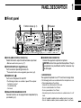
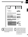
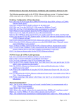
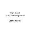
INSTRUCTION MANUAL VHF MOBILE TRANSCEIVER iF5022 UHF MOBILE TRANSCEIVER iF6022 IMPORTANT READ ALL INSTRUCTIONS carefully and completely before using the transceiver. SAVE THIS INSTRUCTION MANUAL — This instruction manual contains important operating instructions for the IC-F5022 VHF MOBILE TRANSCEIVER and the IC-F6022 UHF MOBILE TRANSCEIVER. Icom, Icom Inc. and the Icom logo are registered trademarks of Icom Incorporated (Japan) in the United States, the United Kingdom, Germany, France, Spain, Russia and/or other countries. All other products or brands are registered trademarks or trademarks of their respective holders. EXPLICIT DEFINITIONS WORD RWARNING CAUTION NOTE DEFINITION Personal injury, fire hazard or electric shock may occur. Equipment damage may occur. If disregarded, inconvenience only. No risk of personal injury, fire or electric shock. PRECAUTIONS RWARNING! NEVER connect the transceiver to an AC outlet. This may pose a fire hazard or result in an electric shock. RWARNING! NEVER connect the transceiver to a DO NOT operate the transceiver without running the vehicle’s engine. The vehicle’s battery will quickly run out when the transceiver transmits while the vehicle’s engine is OFF. power source of more than 16 V DC such as a 24 V battery. This connection will ruin the transceiver. DO NOT place the transceiver in excessively dusty envi- RWARNING! NEVER cut the DC power cable between the DC plug and fuse holder. If an incorrect connection is made after cutting, the transceiver might be damaged. DO NOT place the transceiver against walls. This will obstruct heat dissipation. RWARNING! NEVER place the transceiver where when cleaning, as they damage the transceiver surfaces. normal operation of the vehicle may be hindered or where it could cause bodily injury. CAUTION! NEVER allow children to touch the trans- ceiver. CAUTION! NEVER expose the transceiver to rain, snow or any liquids. USE the specified microphone only. Other microphones have ronments. DO NOT use chemical agents such as benzine or alcohol BE CAREFUL! The transceiver will become hot when operating continuously for long periods. Icom optional equipment is designed for optimal performance when used with this transceiver. We are not responsible for the transceiver being damaged or any accident caused when using non-Icom optional equipment. different pin assignments and may damage the transceiver. DO NOT use or place the transceiver in areas with temperatures below –25°C or above +55°C, or in areas subject to direct sunlight, such as the dashboard. ii TABLE OF CONTENTS IMPORTANT........................................................................... i EXPLICIT DEFINITIONS........................................................ i PRECAUTIONS..................................................................... ii TABLE OF CONTENTS........................................................ iii 1. ................. PANEL DESCRIPTION.................................................1−6 ■ Front panel....................................................................1 ■ Function display............................................................2 ■ Programmable function keys.........................................3 3 CONNECTION AND MAINTENANCE.....................14−16 ■ Rear panel connection................................................14 ■ Supplied Accessories..................................................15 ■ Mounting the transceiver.............................................15 ■ Antenna.......................................................................16 ■ Fuse replacement.......................................................16 ■ Cleaning......................................................................16 ■ Options........................................................................16 4.... DOC..........................................................................17−18 2................ BASIC OPERATION...................................................7−13 ■ Turning power ON.........................................................7 ■ Channel selection..........................................................7 ■ Call procedure...............................................................8 ■ Receiving and transmitting............................................8 ■ User set mode.............................................................11 ■ Scrambler function......................................................12 ■ Emergency transmission.............................................12 ■ Stun function...............................................................12 ■ Priority A channel selection.........................................12 ■ MDC 1200 system operation.......................................13 iii PANEL DESCRIPTION 1 ■ Front panel q Function display (p. 2) w e Speaker t r qAF VOLUME CONTROL KNOB [VOL] Rotate the knob to adjust the desired audio output level. • Minimum audio level is pre-set. (p. 11) wUP/DOWN KEYS [CH Up]/[CH Down] Push to select an operating channel, etc. * The desired function can be assigned by your dealer. (p. 3) ePOWER KEY [ ] Push to turn the power ON and OFF. • The following functions are available at power ON as options: - Automatic scan start - Password prompt - Set mode rDEALER-PROGRAMMABLE KEYS Desired functions can be programmed independently by your dealer. (p. 3) tMICROPHONE CONNECTOR Connect the supplied or optional microphone. NEVER connect non-specified microphones. The pin assignments may be different and the transceiver may be damaged. D MICROPHONE The supplied microphone has a PTT switch and a hanger hook. • The following functions are available when the microphone is on or off hook (depending on the setting): - Automatic scan starts when it is on hook. - Scan is cancelled when it is off hook. - Scan is paused when it is off hook. - Automatic priority channel selection is available when it is off hook. - Sets to ‘Inaudible’ condition (mute condition) when it is on hook. - Sets to ‘Audible’ condition (unmute condition) when it is off hook. 1 2 3 4 5 6 7 8 9 10 11 12 13 14 15 16 1 PANEL DESCRIPTION ■ Function display q w e r t y u ySCRAMBLER INDICATOR Appears when the voice scrambler function is activated. i o uBELL INDICATOR Appears/blinks when the specific 2/5-tone/MDC* code is received, according to the pre-programming. iSCAN INDICATOR Blinks during scan. qTRANSMIT INDICATOR Appears while transmitting. wBUSY INDICATOR Appears while the channel is busy. eSIGNAL STRENGTH INDICATOR Indicates relative signal strength level as below. Weak Receive Signal level Strong rLOW POWER INDICATOR Appears when low output power is selected. tAUDIBLE INDICATOR ➥ Appears when the channel is in the ‘Audible’ (unmute) condition. ➥ Appears when the specific 2/5-tone/MDC* code is received. oALPHANUMERIC DISPLAY Displays an operating channel number, channel name, Set mode contents, DTMF code, etc. * MDC operation only (p. 13) PANEL DESCRIPTION 1 ■ Programmable function keys The following functions can be assigned to [UP], [DOWN], [P0], [P1], [P2] and [P3] programmable function keys. Consult your Icom dealer or system operator for details concerning your transceivers programming. If the programmable function names are bracketed in the following explanations, the specific key is used to activate the function depends on the programming. SCAN A START/STOP KEY ➥Push to start and cancel scanning operation. CH UP AND DOWN KEYS ➥Push to select an operating channel. ➥Push to select a transmit code channel after pushing [TX Code CH Select]. ➥Push to select a DTMF channel after pushing [DTMF Autodial]. ➥Push to select a scan group after pushing and holding [Scan A Start/Stop]/[Scan B Start/Stop] for 1 sec. SCAN B START/STOP KEY ➥Push to start and cancel scanning operation. The scan restarts after the specified time period has passed when the scan (started with this key) is cancelled by except for this key operation. ➥Push and hold this key for 1 sec. to indicate the scan list, then push [CH Up] or [CH Down] to select the desired list. ZONE KEY Push this key, then select the desired zone using [CH Up]/ [CH Down]. hat is “zone”?— Selected channels are assigned to a W zone according to how they are to be used in a group. For example, ‘Staff A’ and ‘Staff B’ are assigned into a “Business” zone, and ‘John’ and ‘Cindy’ are assigned into a “Private” zone. • When Power ON Scan function is activated, push to pause the scanning operation. And the paused scan resumes after the specified time period has passed. ➥Push and hold this key for 1 sec. to indicate the scan list, then push [CH Up] or [CH Down] to select the desired list. SCAN ADD/DEL (TAG) KEY ➥Push to add/delete the selected channel to/from the scan list. 1. P ush to indicate the scan group, then push [CH Up] or [CH Down] to select the desired list. 2. P ush to add or delete the channel to/from the selected scan list. 3. Push and hold for 1 sec. to exit the scan list selection mode. 1 2 3 4 5 6 7 8 9 10 11 12 13 14 15 16 ➥Push this key while scan is paused (a signal is detected) on a channel (except for priority channel), the channel is cleared from the scan list. D epending on the setting, the cleared channel is added to the scan list again after the scan is cancelled. 1 PANEL DESCRIPTION PRIO A/B KEYS ➥Push to select Priority A or Priority B channel. ➥Push and hold [Prio A (Rewrite)] or [Prio B (Rewrite)] for 1 sec. to rewrite the operating channel as the Priority A or Priority B channel. LOCK KEY Push and hold to electronically lock all programmable keys except the following: MR-CH 1/2/3/4 KEYS Push to select the memory channel 1 to 4 directly. LONE WORKER KEY Push to turn the Lone Worker function ON or OFF. MONI (AUDI) KEY ➥Push to mute and release the CTCSS (DTCS) or 2-tone squelch mute. Open any squelch/deactivate any mute while pushing and holding this key. (LMR operation only) ➥A ctivates one of (or two of) the following functions on each channel independently: (PMR operation only) • Push and hold to unmute the channel (audio is emitted; ‘Audible’ condition). • Push to mute the channel (sets to ‘Inaudible’ only). • Push after the communication is finished to send a ‘reset code’. (5-tone operation only) OTE: The un-mute condition (‘Audible’ condition) may N automatically return to the mute condition (‘Inaudible’ condition) after a specified period depending on programming. [Moni(Audi)], [Lock], [Call] (incl. Call A and Call B), [Emergency], [Surveillance], [Siren], [Lone Worker] and [OPT 1/2/3]. • If the Lone Worker function is activated, Emergency function is automatically turned ON after the specified time period has passed with no operation is performed. HIGH/LOW KEY Push to select the transmit output power temporarily or permanently, depending on the pre-setting. • Ask your dealer for the output power level for each selection. C.TONE CH ENT KEY Push to enter the continuous tone channel selection mode. Then, push [CH Up]/[CH Down] to change the tone frequency/ code setting. The selected channel remains set as the continuous tone channel until another channel is designated as such. TALK AROUND KEY Push to turn the talk around function ON and OFF. • The talk around function equalizes the transmit frequency to the receive frequency for transceiver-to-transceiver communication. PANEL DESCRIPTION WIDE/NARROW KEY Push to toggle the IF bandwidth between wide and narrow. • The wide passband width can be selected from 25.0 or 20.0 kHz using the CS-F3020/F5020 cloning software. (PMR operation only) Ask your dealer for details. DTMF AUTODIAL KEY ➥P ush to enter the DTMF channel selection mode. And then select the desired DTMF channel using [CH Up]/ [CH Down]. ➥After selecting the DTMF channel, push again to transmit the selected DTMF code. RE-DIAL KEY Push to transmit the last-transmitted DTMF code. • TX memories are cleared after turning the transceiver OFF. CALL KEYS Push to transmit a 2/5-tone ID code. • C all transmission is necessary before calling another station depending on your signalling system. • [ Call A] and/or [Call B] may be available when your system employs selective ‘Individual/Group’ calls. Ask your dealer which call is assigned to each key. 1 EMERGENCY KEY Push and hold this for specified period to transmit an emergency call. 1 • The emergency call transmits with beeps; the display does not change. • The transceiver can transmit an emergency call with no beep emission and LCD indication change depending on the pre-setting. Ask your dealer for details. • If you want to cancel the emergency call, push and hold the key again before transmitting the call. • The emergency call is transmitted one time only or repeatedly until receiving a control code, depending on the pre-setting. SURVEILLANCE KEY Push to turn the surveillance function ON or OFF. When this function is turned ON, the beep is not emitted and the LCD backlight does not light when a signal is received or a key is pushed, etc. SIREN Push to emit a siren. TX CODE ENTER KEY (PMR operation only) Push to enter the TX code edit mode directly. Then set the desired digit using [CH Up]/[CH Down]. (p. 10) 1 PANEL DESCRIPTION TX CODE CHANNEL SELECT KEY ➥Push to enter the TX code channel selection mode. Then set the desired channel using [CH Up]/[CH Down]. (p. 9) ➥While in the TX code channel selection mode, push and hold this key for 1 sec. to enter the TX code edit mode. Then set the desired digit using [CH Up]/[CH Down]. (p. 10) TX CODE CHANNEL UP/DOWN KEYS Push to select a TX code channel directly. ID-MR SELECT KEY (PMR operation only) ➥Recalls detected ID codes. • P ush this key, then select the ID code using [CH Up]/ [CH Down]. • Up to 5 ID’s are memorized. ➥Push and hold this key for 1 sec. to erase the selected ID’s. SCRAMBLER KEY ➥P ush to turn the voice scrambler function ON and OFF. USER SET MODE KEY ➥Push and hold for 1 sec. to enter user set mode. • During user set mode, push this key to select an item*, and change the value or condition using [CH Up]/[CH Down]. *Selectable items may differ depending on the pre-setting. ➥Push and hold this key for 1 sec. again to exit user set mode. User set mode is also available via the ‘Power ON’ function. In this case, all set mode items are available. Refer to p. 11 also. OPT 1/2/3 OUT KEYS Push to control the output signal level from the optional unit connector. OPT 1/2/3 MOMENTARY KEYS Control the output signal level from the optional unit connector while pushing and holding this key. Ext. CH Sel Mode KEY Push to turn the Ext. CH Select function ON or OFF. When the function is turned ON, memory channels can be selected with external input operation only. When the function is turned OFF, memory channels can be selected with [CH Up] or [CH Down] operation, and cannot with external input operation. • This function is available when the external unit, such as a dimmer control is connected to the transceiver with an optional cable, OPC-1939 (p. 16). • Ask your dealer for details of external input operation. BASIC OPERATION 2 ■ Turning power ON ■ Channel selection qPush [ ] to turn the power ON. wIf the transceiver is programmed for a start up password, input the digit codes as directed by your dealer. Several types of channel selections are available. Methods may differ according to your system set up. • The keys as below can be used for password input: The transceiver detects numbers in the same block as identical. Therefore “01234” and “56789” are the same. NON-ZONE TYPE: Push [CH Up] or [CH Down] to select the desired operating channel, in sequence; or, push one of [MR-CH 1] to [MR-CH 4] keys to select a channel directly. KEY NUMBER 0 1 2 3 4 5 6 7 8 9 eWhen the “PASSWORD” indication does not clear after inputting 4 digits, the input code number may be incorrect. Turn the power off and start over in this case. ZONE TYPE: Push [Zone], then push [CH Up] or [CH Down] to select the desired zone. AUTOMATIC SCAN TYPE: Channel setting is not necessary for this type. When turning power ON, the transceiver automatically starts scanning. Scanning stops when receiving a call. 1 2 3 4 5 6 7 8 9 10 11 12 13 14 15 16 2 BASIC OPERATION ■ Call procedure ■ Receiving and transmitting When your system employs tone signaling (excluding CTCSS and DTCS), a call procedure may be necessary prior to voice transmission. The tone signalling employed may be a selective calling system which allows you to call specific station(s) only and prevents unwanted stations from contacting you. Receiving: qPush and hold [ ] for 1 sec. to turn the power ON. wPush [CH Up] or [CH Down] to select a channel, in sequence. eWhen receiving a call, rotate [VOL] to adjust the audio output level to a comfortable listening level. qSelect the desired TX code channel, 2/5-tone code according to your System Operator’s instructions. Transmitting: Wait for the channel to become clear to avoid interference. qTake the microphone off hook. • This may not be necessary depending on programming. • Refer to pages 9–10 for selection. wPush [Call] (assigned to one of the dealer programmable keys). eAfter transmitting, the remainder of your communication can be carried out in the normal fashion. Selective calling Non-selective calling • The ‘audible’ condition is selected. • A priority channel may be selected automatically. wWait for the channel to become clear. • The channel is busy when BUSY indicator appears on the LCD. eWhile pushing and holding [PTT], speak into the microphone at your normal voice level. rRelease [PTT] to return to receive. IMPORTANT: To maximize the readability of your signal; 1. Pause briefly after pushing [PTT]. 2. Hold the microphone 5 to 10 cm (2 to 4 inches) from your mouth, then speak into the microphone at a normal voice level. BASIC OPERATION D Transmitting notes •Transmit inhibit function The transceiver has several inhibit functions which restrict transmission under the following conditions: - The channel is in mute condition (‘Inaudible’ condition; “ ” (Audible indicator) does not appear.) - The channel is busy. - Un-matched (or matched) CTCSS is received. (Depending on the pre-setting) - The selected channel is a ‘receive only’ channel. •Time-out timer After continuous transmission for the pre-programmed time period, the time-out timer is activated, causing the transceiver to stop transmitting. •Penalty timer Once the time-out timer is activated, transmission is further inhibited for a period determined by the penalty timer. •PTTID call The transceiver sends the ID code (5-tone, DTMF or digital ANI) automatically when [PTT] is pushed (beginning of the transmission) and/or released (end of transmission) depending on the setting. P TTID call is also available with the MDC 1200 signaling system. (p. 13) 2 D TX code channel selection If the transceiver has [TX Code CH Select] assigned to it, the indication can be toggled between the operating channel number (or name) and TX code channel number (or name). When the TX code channel number (or name) is displayed, [CH Up] or [CH Down] selects the TX code channel. USING [TX CODE CH SELECT] KEY: qPush [TX Code CH Select]— a TX code channel number (or name) appears. wPush [CH Up] or [CH Down] to select the desired TX code channel. eAfter selecting, push [TX Code CH Select] to set. • Return to the stand-by mode. rPush [Call] to transmit the selected TX code. USING [TX CODE CH UP]/[TX CODE CH DOWN] KEY: If the transceiver has a [TX Code CH Up] or [TX Code CH Down] key assignment, the programmed TX code channel can be selected directly when pushed. 1 2 3 4 5 6 7 8 9 10 11 12 13 14 15 16 2 BASIC OPERATION D TX code number edit (PMR operation only) If the transceiver has [TX Code CH Select] or [TX Code Enter] assigned to it, TX code contents can be edited within the allowable digits. USING [TX CODE CH SELECT] KEY: qPush [TX Code CH Select] to enter the TX code channel selection mode. • Select the desired operating channel before entering the TX code channel selection mode if necessary. wPush [TX Code CH Select] for 1 sec. to enter the TX code edit mode. • The digit to be edited blinks. ePush [TX Code CH Select] to select the desired digit to be edited. rPush [CH Up] or [CH Down] to select the desired digit. tPush [TX Code CH Select] to set. The digit to the right will blink automatically. yRepeat r and t to edit all allowable digits. uAfter editing, push [TX Code CH Select] to set. • Return to the stand-by mode. iPush [Call] to transmit. 10 USING [TX CODE ENTER] KEY: qPush [TX Code Enter] to enter the TX code edit mode. • The digit to be edited blinks. wPush [TX Code Enter] to select the desired digit to be edited. ePush [CH Up] or [CH Down] to select the desired digit. rPush [TX Code Enter] to set. The digit to the right will blink automatically. tRepeat e and r to edit all allowable digits. yAfter editing, push [TX Code Enter] to set. • Return to the stand-by mode. uPush [Call] to transmit. D DTMF transmission If the transceiver has [DTMF Autodial] assigned to it, the automatic DTMF transmission function is available. Up to 8 DTMF channels are available. qPush [DTMF Autodial]— a DTMF channel appears. wPush [CH Up] or [CH Down] to select the desired DTMF channel. ePush [DTMF Autodial] to transmit the DTMF code. BASIC OPERATION 2 ■ User set mode User set mode can be accessed with ‘Power ON’ function. In this case, all set mode items are available. User set mode allows you to set seldom-changed settings and you can “customize” the transceiver operation to suit your preferences and operating style. Entering the user set mode: qWhile pushing and holding [P1] and [P2], push [ the power ON. [ • Available set mode functions are Backlight, Beep, Beep Level, SQL Level, AF Min Level, Mic Gain, Horn, Battery Voltage, Signal Moni and Lone Worker. [P0] [Up]/[Down] rPush and hold [ ] for 1 sec. to turn power OFF, then ON again to exit set mode. ] wPush and hold [P0] for 1 sec. to enter user set mode. [P0] 2 ] to turn • Turn power OFF in advance. • Push and hold [P1] and [P2] continuously until “SET MODE” appears on the display. [P1] [P2] ePush [P0] several times to select the appropriate item. Then, push [Up] or [Down] to set the desired level/condition. [ ] User set mode is also available using a programmable key. Please refer to p. 6 [User Set Mode] section for instructions regarding using the key assigned for user set mode. [User Set Mode] is allowed for the quick item selection. Set “Enable” for the often used items with the CS-F3020/F5020 cloning software. 11 2 BASIC OPERATION ■ Scrambler function ■ Stun function The voice scrambler function provides private communication between stations. All versions have a built-in frequency inversion type scrambler, moreover, the optional Rolling or Non-rolling type can be available. When the specified ID, set as a stun ID or kill ID, is received, the stun function is activated. When the stun ID is received, the transceiver becomes unusable. Entering of the password (p. 8) or receiving a specified ID, set as a revive ID, is necessary to operate the transceiver again in this case. When the kill ID is received, the transceiver switches to the cloning required condition. Cloning the transceiver is necessary to operate the transceiver again in this case. qPush [Scrambler] to turn the scrambler function ON. •“ ” (Scrambler indicator) appears. wP ush [Scrambler] again to turn the scrambler function OFF. •“ ” disappears. ■ Emergency transmission The emergency call can be performed using [Emergency]. (p. 5) When [Emergency] is pushed for the specified time period, the DTMF or 5-tone emergency signal is transmitted once or repeatedly on the emergency channel depending on the channel. However, when no emergency channel is specified, the signal is transmitted on the previously selected channel. If you want to cancel the emergency call, push and hold the key again before transmitting the call. Emergency call is also available with the MDC 1200 signaling system. (p. 13) 12 Stun function is also available with the MDC 1200 signaling system. (p. 13) ■ Priority A channel selection When one of the following operations is performed, the transceiver selects the Priority A channel automatically. •Turning the power ON The Priority A channel is selected each time the transceiver power is turned ON. •Off hook. The Priority A channel is selected when the microphone is took off from its hanger. BASIC OPERATION 2 ■ MDC 1200 system operation The MDC 1200 signaling system enhances your transceiver’s capabilities. It allows PTT ID*, Emergency signaling, and receiving Radio Check. Also, the dispatcher can stun and revive transceivers on the system. An additional feature of MDC 1200 system found in Icom transceivers is called aliasing. Each transceiver on the system has a unique ID number. Aliasing allows the substitution of an alphanumeric name for this ID number. For transmit, you can use this alias to select a transceiver to call. For receive, the alias of the calling station is displayed instead of the ID. *When [PTT] is pushed and/or released, the transceiver transmits your own station ID. D Receiving an Emergency Call qWhen an emergency call is received; • Beeps sound. • The calling station ID (or alias) and “EMG EMG” are displayed alternately. wTurn power OFF, change the channel, push [PTT] for replying the call, etc. to stop the beep and display indication. D Transmitting an Emergency Call The MDC 1200 system Emergency feature can be accessed using the [Emergency] key (p. 5). The transceiver will send an Emergency MDC 1200 system command once or repeatedly for a programmed number of times until it receives the acknowledgement signal. The emergency call can be transmitted without a beep emission, and the LCD indication change depends on how emergency is programmed. Ask your dealer for details. D Receiving a Stun and Revive The dispatcher can send MDC 1200 system signals that will stun or revive your transceiver. If a Stun command is received that matches your station ID, the transceiver will display “SORRY” (default) and you can not receive or transmit. When a Revive command is received that matches your station ID, normal operation is restored. 1 2 3 4 5 6 7 8 9 10 11 12 13 14 15 16 13 3 CONNECTION AND MAINTENANCE ■ Rear panel connection Antenna q ANTENNA CONNECTOR Connects to an antenna. Contact your dealer about antenna selecton and placement. w EXTERNAL S.EAKER JACK Connect a 4–8 ø external speaker. e MICRO.HONE HANGER Connect the suppled mcrophone hanger to the vehcle’s ground for mcrophone on/off hook functons. (See p. 1) q Optonal speaker e w CAUTION: NEVER remove the fuse-holder from the DC power cable. t Red Black 1.2V Battery 14 NOTE: Use the termnals as shown below for the cable connectons. Crmp Solder r r O.TIONAL CABLE (O.C-1.939) Connect an external modem, dmmer control, etc. t DC .OWER RECE.TACLE Connects to a 12 V DC battery. Pay attenton to polartes. NEVER connect to a 24 V battery. Ths could damage the transcever. CONNECTION AND MAINTENANCE ■ Supplied Accessories Microphone Microphone hanger and screw set Microphone hanger cable DC power cable Function name stickers* Mounting bracket ■ Mounting the transceiver The universal mounting bracket supplied with your transceiver allows overhead mounting. • Mount the transceiver securely with the 4 supplied screws to a thick surface which can support more than 1.5 kg. Flat washer Felt* Spring washer Flat washers Nuts Mounting screws (M5×12) Spring washers Bracket bolts Self-tapping screws (M5×20) * Used for labelling the programmable function 3 Felt* When using self-tapping screws 1 2 3 4 5 6 7 8 9 10 11 12 13 14 15 16 *Felts reduce the vibration effects. keys according to their assinged functions. 15 3 CONNECTION AND MAINTENANCE ■ Antenna A key element in the performance of any communication systems is an antenna. Contact your dealer for more information regarding antennas and how to install them. ■ Options • OPC-1132A/OPC-347 dc power cable 2 fuse holders are attached. USE the 20 A fuse only. OPC-1132A: 3 m (9.8 ft) OPC-347: 7 m (23 ft) ■ Fuse replacement • OPC-1939 acc cable Allows you to connect to an external terminal. A fuse is installed in the supplied DC power cable. If a fuse blows or the transceiver stops functioning, track down the source of the problem if possible, and then replace the damaged fuse with a new rated one. • HM-152/HM-152T/HM-148G/HM-148T hand microphone HM-152 : Hand microphone HM-152T : DTMF microphone HM-148G : Self ground heavy duty microphone HM-148T : Self ground heavy duty microphone with 10-keypad ❑ Fuse rating: 10 A USE the 10 A fuse only. • SM-25 desktop microphone • SP-5/SP-10/SP-22 external speaker Input impedance :4ø Max. input power : 5 W SP-5 : Large speaker for good audio quality. SP-10 : For all-round mobile operation. SP-22 : Compact and easy-to-install. ■ Cleaning If the transceiver becomes dusty or dirty, wipe it clean with a soft, dry cloth. 16 AVOID the use of solvents such as benzene or alcohol, as they may damage the transceiver surfaces. • UT-108R dtmf decoder unit Provides pager and code squelch capabilities. • UT-109R/UT-110R scrambler units Non-rolling type (UT-109R)/Rolling type (UT-110R) voice scrambler unit provides higher communication security. DOC 4 DECLARATION OF CONFORMITY We Icom Inc. Japan 0168 1-1-32, Kamiminami, Hirano-ku Osaka 547-0003, Japan Declare on our sole responsibility that this equipment complies with the essential requirements of the Radio and Telecommunications Terminal Equipment Directive, 1999/5/EC, and that any applicable Essential Test Suite measurements have been performed. Kind of equipment: VHF TRANSCEIVER Type-designation: iC-f5022 Version (where applicable): 136–174 MHz 12.5 kHz/25 kHz 136–174 MHz 12.5 kHz/20 kHz This compliance is based on conformity with the following harmonised standards, specifications or documents: i) EN 301 489-1 v1.6.1 (September 2005) ii) EN 301 489-5 v1.3.1 (August 2002) iii) EN 300 086-2 v1.1.1 (March 2001) iv) EN 300 219-2 v1.1.1 (March 2001) v) EN 300 113-2 v1.3.1 (December 2003) vi) EN 60950-1: 2001 vii) viii) CE Versions of the IC-F5022 which display the “CE” symbol on the serial number seal, comply with the essential requirements of the European Radio and Telecommunication Terminal Directive 1999/5/EC. Düsseldorf 15th Jan. 2009 Place and date of issue Authorized representative name Y. Furukawa General Manager Signature This warning symbol indicates that this equipment operates in non-harmonised frequency bands and/or may be subject to licensing conditions in the country of use. Be sure to check that you have the correct version of this radio or the correct programming of this radio, to comply with national licensing requirement. 1 2 3 4 5 6 7 8 9 10 11 12 13 14 15 16 17 4 DOC • List of Country codes (ISO 3166-1) 1 2 3 4 5 6 7 8 9 10 11 12 13 14 15 16 17 Country Codes Austria Belgium Bulgaria Croatia Czech Republic Cyprus Denmark Estonia Finland France Germany Greece Hungary Iceland Ireland Italy Latvia AT BE BG HR CZ CY DK EE FI FR DE GR HU IS IE IT LV 18 19 20 21 22 23 24 25 26 27 28 29 30 31 32 33 Country Codes Liechtenstein Lithuania Luxembourg Malta Netherlands Norway Poland Portugal Romania Slovakia Slovenia Spain Sweden Switzerland Turkey United Kingdom LI LT LU MT NL NO PL PT RO SK SI ES SE CH TR GB About e-marking: Detailed installation notes for Icom mobile transceivers to be fitted into vehicles are available. Please contact your Icom dealer or distributor. 18 MEMO 1 2 3 4 5 6 7 8 9 10 11 12 13 14 15 16 < Intended Country of Use > AT FI IT PL GB RO BE FR LV PT IS TR A-6732D-1EU Printed in Japan © 2009 Icom Inc. Printed on recycled paper with soy ink. CY DE LT SK LI HR CZ GR LU SI NO DK HU MT ES CH EE IE NL SE BG 1-1-32 Kamiminami, Hirano-ku, Osaka 547-0003, Japan