1
Air-To-Water Heat Exchangers
WCHE Models
INSTRUCTION MANUAL
Rev. G
© 2013 Pentair Equipment Protection
P/N 89087983
89087984
TABLE OF CONTENTS
HOW TO CONSULT THIS MANUAL..................................................................................................................................................................... 3
THIS MANUAL IS INTENDED FOR THE FOLLOWING:..........................................................................................................................................................3
PURPOSE OF THE INFORMATION CONTAINED IN THIS MANUAL:.....................................................................................................................................3
RESTRICTIONS TO THE USE OF THIS MANUAL...................................................................................................................................................................3
WHERE AND HOW TO STORE THIS MANUAL.......................................................................................................................................................................3
CURRENT TECHNOLOGY.......................................................................................................................................................................................................3
UPDATES................................................................................................................................................................................................................................3
IN THE EVENT OF SALE OF THE PRODUCT..........................................................................................................................................................................3
UNPACKING AND INSPECTION......................................................................................................................................................................... 4
Included in the carton:...........................................................................................................................................................................................................4
UNIT IDENTIFICATION...........................................................................................................................................................................................................4
SAFETY REMARKS............................................................................................................................................................................................. 5
PRECAUTIONS WHEN HANDLING THE UNIT.......................................................................................................................................................................5
OPERATING PRINCIPLE..................................................................................................................................................................................... 6
COOLING CAPACITY...............................................................................................................................................................................................................7
Performance Data WCHE019 Series.....................................................................................................................................................................................7
Design Data WCHE019 Series............................................................................................................................................................................ 8
Performance Data WCHE049 Series.....................................................................................................................................................................................9
Design Data WCHE049 Series.......................................................................................................................................................................... 10
Performance Data WCHE069 Series...................................................................................................................................................................................11
Design Data WCHE069 Series.......................................................................................................................................................................... 12
Performance Data WCHE149 Series...................................................................................................................................................................................13
Design Data WCHE149 Series.......................................................................................................................................................................... 14
INSTALLATION INSTRUCTIONS....................................................................................................................................................................... 15
Installation............................................................................................................................................................................................................................15
WATER CONNECTIONS........................................................................................................................................................................................................16
MECHANICAL PARTS....................................................................................................................................................................................... 18
STRUCTURE.........................................................................................................................................................................................................................18
HEAT EXCHANGE BANK......................................................................................................................................................................................................18
CONDENSATE COLLECTION BASIN....................................................................................................................................................................................18
FLOW CONTROL SOLENOID VALVE.....................................................................................................................................................................................18
MOTORS............................................................................................................................................................................................................ 19
FANS.....................................................................................................................................................................................................................................19
CONTROL, MONITORING AND SAFETY COMPONENTS................................................................................................................................. 19
REGULATING THERMOSTAT FOR SOLENOID VALVE..........................................................................................................................................................19
Adjustments.................................................................................................................................................................................................................19
ELECTRICAL CONNECTIONS........................................................................................................................................................................... 20
WCHE019 only......................................................................................................................................................................................................................20
WCHE049, WCHE069, WCHE149.........................................................................................................................................................................................21
START-UP......................................................................................................................................................................................................... 21
TEMPERATURE CONTROL............................................................................................................................................................................... 21
PRELIMINARY CHECKS AFTER STARTING THE UNIT.................................................................................................................................... 21
TURNING OFF THE UNIT................................................................................................................................................................................. 21
MAINTENANCE................................................................................................................................................................................................. 22
PREVENTATIVE MAINTENANCE SCHEDULE......................................................................................................................................................................22
Twice a year.................................................................................................................................................................................................................22
Annually.......................................................................................................................................................................................................................22
REPLACEMENT OF COMPONENTS............................................................................................................................................................................22
HOW TO CLEAN THE UNIT..........................................................................................................................................................................................22
INACTIVITY...................................................................................................................................................................................................................22
INFORMATION ON RESIDUAL HAZARDS AND EMERGENCY SITUATIONS................................................................................................... 23
GENERAL SAFETY PROVISIONS.................................................................................................................................................................................23
HAZARDS ARISING FROM THE PRODUCT COMING INTO CONTACT WITH THINGS OR PERSONS��������������������������������������������������������������������������������23
SAFETY STANDARDS FOR ELECTRICAL EQUIPMENT.......................................................................................................................................................23
Introduction..................................................................................................................................................................................................................23
TASKS ASSIGNED TO OFFICERS-IN-CHARGE....................................................................................................................................................................23
HIGH VOLTAGE......................................................................................................................................................................................................................23
SAFETY STANDARDS TO COMPLY WITH WHEN THE EQUIPMENT IS TURNED OFF........................................................................................................24
SAFETY STANDARDS TO COMPLY WITH WHEN SERVICING LIVE EQUIPMENT...............................................................................................................24
SAFETY STANDARDS TO COMPLY WITH WHEN SERVICING THE UNIT............................................................................................................................24
FIRE HAZARDS.....................................................................................................................................................................................................................24
TOXIC SUBSTANCES............................................................................................................................................................................................................24
DANGERS ARISING FROM FLUIDS......................................................................................................................................................................................24
DISASSEMBLING THE UNIT............................................................................................................................................................................ 25
TROUBLE SHOOTING....................................................................................................................................................................................... 26
Symptoms and Possible Causes:........................................................................................................................................................................................26
Replacement Parts...............................................................................................................................................................................................................27
WARRANTY....................................................................................................................................................................................................... 30
RETURN AND REPAIR POLICY........................................................................................................................................................................ 30
LIMITATION OF LIABILITY................................................................................................................................................................................ 31
NOTE: Please read this manual carefully before installing the unit. This user manual is an
integral part of the product and should accompany it until it is eventually disassembled.
-2-
© 2013 Pentair Equipment Protection
89087984
HOW TO CONSULT THIS MANUAL
This document contains general information applicable to all models. In the event of any information updates
becoming necessary, such updates shall be inserted in the enclosures.
THIS MANUAL IS INTENDED FOR THE FOLLOWING:
•
•
•
•
•
Owner of the appliance
Person responsible for its installation
Person responsible for managing the product
Person responsible for ordinary maintenance
Person responsible for its disassembly
PURPOSE OF THE INFORMATION CONTAINED IN THIS MANUAL:
•
•
•
•
•
CORRECT HANDLING: performed by unskilled personnel
CORRECT INSTALLATION: performed by skilled personnel
CORRECT MANAGEMENT: performed by skilled personnel
CORRECT MAINTENANCE: performed by skilled personnel
CORRECT ORDER FOR SPARE PARTS: CORRECT DISPOSAL OF THE PRODUCT: made by skilled personnel
RESTRICTIONS TO THE USE OF THIS MANUAL
They apply to any operations that must be performed by highly skilled personnel.
WHERE AND HOW TO STORE THIS MANUAL
Inside the electric cabinet or together with any other literature concerning the equipment which utilizes
the product, provided it is a dry and clean place.
In the event of the manual being misplaced or damaged, the customer may require, for a fee, a new
manual, by quoting the model and serial number shown on the technical name- plate, by contacting:
Pentair Equipment Protection
2100 Hoffman Way
Minneapolis MN 55303 USA
1-763-323-8200
CURRENT TECHNOLOGY
This manual reflects the state of the art existing at the time the product is marketed and shall not
be deemed to be inadequate for the sole reason that it has not been updated as a result of any new
experience.
UPDATES
Pentair Equipment Protection reserves the right to update the product and relevant manual without being
required to update previous products and manuals other than in exceptional circumstances. To require or
receive any updates of the instructions manual or amendments thereto, which shall be deemed to be an
integral part of the manual, please contact Pentair Equipment Protection.
Any suggestions or recommendations made by installers or users of the product for the purpose of
improving the product or the contents of this manual, will be greatly appreciated by the Manufacturer.
IN THE EVENT OF SALE OF THE PRODUCT
Please advise Pentair Equipment Protection of the address of the new owner so as to enable the dispatch
of any updates to the manual, otherwise Pentair Equipment Protection shall be relieved of any subsequent
liabilities.
89087984
© 2013 Pentair Equipment Protection
-3-
UNPACKING AND INSPECTION
Hoffman® cooling branded products are shipped ex-works. All units have been individually inspected and carefully
packaged.
Immediately inspect the unit upon receipt, making sure it has been shipped in its proper position. Note improper
shipment on the shipping document. We recommend accepting merchandise subject to inspection.
Check for damage and, if any, note this immediately on the shipping document.
Remove packing and check that the exterior casing is not scratched, marked or have signs of blows and that no
components are missing.
Before throwing the packaging away, check that it does not contain documents or additional parts of the unit.
Any damage that is encountered must be communicated to the carrier by registered letter within 8 days of receipt.
The carrier is responsible for any damage caused during shipment.
Pentair Equipment Protection is not responsible for damage caused to the merchandise by the shipper but will do
all in its power to assist customers in these situations.
INCLUDED IN THE CARTON:
•
•
•
•
•
Heat Exchanger
Mounting fastener kit
Mounting gasket
G-NPT Adapting Valves (2)
User Manual
NOTE: This product may not be returned without prior written approval by Pentair Equipment
Protection.
NOTE: If installation of the product is not immediately required or the product needs to be
transported to its final destination, repackage it after your initial inspection, and store it in a
safe place.
UNIT IDENTIFICATION
This unit can be correctly identified by the technical nameplate containing all the information for its
correct use.
The technical name-plate is embossed on a plastic support which ensures high endurance of the text even
in particularly difficult environments.
Note: The serial number is required for any assistance or information concerning the unit
described in this manual.
-4-
© 2013 Pentair Equipment Protection
89087984
SAFETY REMARKS
Operation and maintenance of the heat exchangers can be dangerous if not carried out with the same care as
given to other appliances that have moving parts and electric components next to water.
Only skilled personnel may repair, inspect or maintain the heat exchangers.
Before servicing this unit, refer to the instructions contained in this manual, check the data on the name-plate
and follow any other precaution to ensure absolute safety.
WARNING
Disconnect power before working on the unit.
PRECAUTIONS WHEN HANDLING THE UNIT
Metal edges may be sharp. Be careful handling the unit, and always wear gloves.
89087984
© 2013 Pentair Equipment Protection
-5-
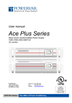
OPERATING PRINCIPLE
Hoffman cooling branded air-to-water heat exchangers are designed for cooling electric cabinets with
either a Type 12 or IP55 protection and are suitable for operating in industrial environments. These
models eliminate problems caused by high temperatures of the cabinet and prevent dirt and dust from
penetrating inside the electric board.
CAUTION
It is required that the water temperature be lower than the
cabinet temperature for the air-to-water heat exchanger to work
properly.
Cooling water, a constant flow of which must be furnished by the user at a temperature that is lower than the
temperature in the cabinet, passes through the tubes in a heat exchanger with copper tubes and aluminum fins
and back into the cabinet.
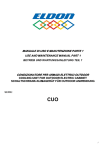
Heat is transferred through the walls of the copper tubes, exchanging heat from the fins to the cold water so that
the air exits cooler and the water hotter.
Note: The greater the difference between these two temperatures the more heat is
exchanged.
Tem perature trend
°C 60
50
40
∆t
30
20
10
0
tim e
internal temp.
w ater temp.
CABINET
AMBIENT
WATER
-6-
© 2013 Pentair Equipment Protection
89087984
COOLING CAPACITY
This depends on the specific exchange factor of the heat exchanger (indicated on the label) and the
temperature difference between the interior of the cabinet and the cooling water.
FOR EXAMPLE:
Model: WCHE04916
Capacity noted on label: 2200W @ 25 C ∆T
Specific heat transmission: 2200 / 25 = 88W/°C
Application:
Maximum internal cabinet temperature desired: 40 C
Maximum estimated water temperature: 20 C
∆T Difference: 20 C
Cooling capacity: 88 x 20 = 1760W
PERFORMANCE DATA WCHE019 SERIES
Parameter
Voltage / Phase / Frequency
Units
WCHE01916002
WCHE01926002
V/ph/Hz
115/1/50-60
230/1/50-60
Cooling capacity L35W10 (25°C dT)
W
870
Power absorbed
W
28
Current absorbed
A
0.5
CFM (m3/h)
118 (200)
Recommended water flow
gpm (l/h)
0.66 (150)
Pressure drop at recommended water
flow
psi (kPa)
0.3 (2)
Max water pressure
psi (kPa)
73 (500)
Water connections (using valves)
NPT
3/8 inch
Operating temperature Min/Max
°F (°C)
50/122 (10/50)
Noise level (measured at 1m)
dB(A)
58
%
100
Max airflow through heat exchanger
Duty cycle
Protective system side cabinet
Type 12 / IP55
Protective system side ambient
IP55
Weight
Electrical connection
89087984
lb (kg)
20 (9)
6 foot (1.8m) cord with
NEMA 5-15P
© 2013 Pentair Equipment Protection
6 foot (1.8m) cord with
NEMA 6-15P
-7-
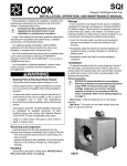
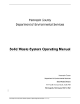
DESIGN DATA WCHE019 SERIES
)5217
002817,1*+2/(6
%$&.
(1&/2685(
$,5,1
)705()
32:(5&25':,7+3/8*
(1&/2685(
$,5287
89090291
&21'(16$7(
'5$,178%(
:$7(5
287
:$7(5
,1
5()
%336*)(0$/(
:$7(5&211(&7,21
5()
5()
5()
&87287
-8-
© 2013 Pentair Equipment Protection
89087984
PERFORMANCE DATA WCHE049 SERIES
Parameter
Voltage / Phase / Frequency
Units
WCHE04916002
WCHE04926002
V/ph/Hz
115/1/50-60
230/1/50-60
Cooling capacity L35W10 (25°C dT)
W
Power absorbed
W
90
Current absorbed
A
0.8
CFM (m3/h)
247 (420)
Recommended water flow
gpm (l/h)
0.66 (150)
Pressure drop at recommended water
flow
psi (kPa)
4.4 (30)
Max water pressure
psi (kPa)
145 (1000)
Max airflow through heat exchanger
2200
Water connections (using valves)
NPT
1/2 inch
Operating temperature Min/Max
°F (°C)
50/122 (10/50)
Noise level (measured at 1m)
dB(A)
58
Protective system side cabinet
Type 12 / IP55
Protective system side ambient
IP55
Duty cycle
Weight
Electrical connection
89087984
%
100
lb (kg)
44 (20)
6 foot (1.8m) cord with
NEMA 5-15P
© 2013 Pentair Equipment Protection
6 foot (1.8m) cord with
NEMA 6-15P
-9-
DESIGN DATA WCHE049 SERIES
002817,1*+2/(6
)5217
(1&/2685(
$,5,1
)705()
32:(5&25':,7+3/8*
(1&/2685(
$,5287
89090292
&21'(16$7(
'5$,178%(
:$7(5 :$7(5
,1
287
5()
%336*)(0$/(
:$7(5&211(&7,21
5()
5()
5()
5()
&87287
- 10 -
© 2013 Pentair Equipment Protection
89087984
PERFORMANCE DATA WCHE069 SERIES
Parameter
Voltage / Phase / Frequency
Units
WCHE06916002
WCHE06926002
V/ph/Hz
115/1/50-60
230/1/50-60
Cooling capacity L35W10 (25°C dT)
W
3100
Power absorbed
W
115
Current absorbed
A
1
CFM
(m3/h)
265 (450)
Recommended water flow
gpm (l/h)
2.2 (500)
Pressure drop at recommended water flow
psi (kPa)
9.1 (63)
Max water pressure
psi (kPa)
145 (1000)
Max airflow through heat exchanger
Water connections (using valves)
NPT
1/2 inch
Operating temperature Min/Max
°F (°C)
50/122 (10/50)
Noise level (measured at 1m)
dB(A)
58
Protective system side cabinet
Type 12 / IP55
Protective system side ambient
IP55
Duty cycle
Weight
Electrical connection
89087984
%
100
lb (kg)
46 (21)
6 foot (1.8m) cord with
NEMA 5-15P
© 2013 Pentair Equipment Protection
6 foot (1.8m) cord with
NEMA 6-15P
- 11 -
DESIGN DATA WCHE069 SERIES
)5217
002817,1*+2/(6
(1&/2685(
$,5,1
)705()
32:(5&25':,7+3/8* (1&/2685(
$,5287
89090293
&21'(16$7(
'5$,178%(
%336*)(0$/(
:$7(5&211(&7,21
5()
5()
5()
5()
5()
:$7(5 :$7(5
,1
287
&87287
- 12 -
© 2013 Pentair Equipment Protection
89087984
PERFORMANCE DATA WCHE149 SERIES
Parameter
Voltage / Phase / Frequency
Units
WCHE14916002
WCHE14926002
V/ph/Hz
115/1/50-60
230/1/50-60
Cooling capacity L35W10 (25°C dT)
W
Power absorbed
W
200
245
Current absorbed
A
2
1.3
Max airflow through heat exchanger
6700
CFM (m3/h)
500 (850)
Recommended water flow
gpm (l/h)
3.8 (860)
Pressure drop at recommended water flow
psi (kPa)
5.8 (40)
Max water pressure
psi (kPa)
145 (1000)
Water connections (using valves)
NPT
1/2 inch
Operating temperature Min/Max
°F (°C)
50/122 (10/50)
Noise level (measured at 1m)
dB(A)
58
Protective system side cabinet
Type 12 / IP55
Protective system side ambient
IP55
Duty cycle
Weight
Electrical connection
89087984
%
100
lb (kg)
86 (39)
6 foot (1.8m) cord with
NEMA 5-15P
© 2013 Pentair Equipment Protection
6 foot (1.8m) cord with
NEMA 6-15P
- 13 -
DESIGN DATA WCHE149 SERIES
002817,1*+2/(6
(1&/2685(
$,5,1
)5217
)705()
32:(5&25':,7+3/8*
(1&/2685(
$,5287
89090294
&21'(16$7(
'5$,178%(
5()
:$7(5 :$7(5
,1
287
%336*)(0$/(
:$7(5&211(&7,21
5()
5()
5()
5()
5()
&87287
- 14 -
© 2013 Pentair Equipment Protection
89087984
INSTALLATION INSTRUCTIONS
Before installing, check the following:
•
•
•
•
•
•
The cabinet is Type 12 or IP55 type, depending on the overall rating required
There is enough room for an easy application and installation, both inside and outside the cabinet
The cabinet is clean on the inside
The cabinet is not in the vicinity of heat sources or warm air flows
The inside of the cabinet allows a proper air circulation, preventing any recirculation
There is enough clearance to remove the outer cover and access the components.
For wall-mount applications, the following safety instructions must be complied with:
•
•
•
•
•
The heat exchanger must be installed as high as possible
If it is installed on a door, make sure that the hinges are strong enough to support the unit
Make sure that the electric cable does not get torn or damaged with the door closed
If the depth of the heat exchanger blocks the entire door opening clearance, provide a door stop for it
Cabinet panel must be flat and rigid to form a tight seal with the mounting gasket.
INSTALLATION
NOTE: Prior to drilling holes or making cuts on the cabinet, make sure that holes, screws,
cables, etc. do not interfere with the equipment which has already been installed.
1. Identify the proper cutout drawing for the model being installed. Paper templates (included with
the unit) are marked with EXW## designations. The cross reference below indicates the template
for each model. Cutout drawings are also shown in this manual.
Model
Template Marking
WCHE019
EXW06
WCHE049
EXW15
WCHE069
EXW25
WCHE149
EXW50
2. Make cuts on the cabinet panels by following the relevant template. Remove any chips, burrs or
sharp edges.
3. Attach the adhesive gasket (included) to the mounting surface of the heat exchanger as shown.
4. Place the heat exchanger against the cabinet and secure it with the appropriate screws (included).
Verify cabinet panel forms a tight seal with the mounting gasket.
3/$&(*$6.(76+(5(
3/$&(*$6.(76
+(5(
29(5/$3%27720*$6.(7
,16,'(723*$6.(7PP
89086208
29(5/$3*$6.(76PP
WCHE019 ONLY
89087063
ALL OTHER MODELS
),(/'$33/,&$7,212)02817,1**$6.(7
89087984
© 2013 Pentair Equipment Protection
- 15 -
WATER CONNECTIONS
1. Make plumbing connections using the on/off valves included. The connections on the unit are ‘G’
thread. ‘G’ to NPT adapting valves are included. Do not connect NPT fittings directly to the heat
exchanger, as the threads are not compatible and the connection will leak.
Note: Once unit is connected to water, PROTECT THE UNIT FROM FREEZING. Even after it is
disconnected, the heat exchanger will hold water and could be severely damaged by freezing
temperatures.
2.
3.
4.
5.
Make sure the pressure in the plumbing circuit does not exceed admissible values.
Introduce water into the circuit, making sure there are no leaks from pipelines.
Install an inlet and an outlet pressure gauge on the plumbing circuit plus a gate valve.
This will permit you to control the speed of the water inside the heat exchange coil and avoid
dangerous corrosion of the copper piping.
6. This is done by adjusting the gate valve so that the pressure gauges show a pressure difference
that is approximately equal to the stated load losses.
Note: If the unit contains a solenoid valve, it will allow flow of water only when the unit is
powered and calling for cooling.
For example: WCHE06916 stated pressure drop: 9.1 psi. The difference between inletpressure value and out-pressure value ~9 psi.
7. For correct use of the heat exchanger and to avoid corrosion, the water used for the heat
exchanger must have hydrological values as listed:
- 16 -
© 2013 Pentair Equipment Protection
89087984
Chemical parameters of the circuit water
Characteristic
Parameter
Langelier index
-0.2 < L < +0.4
Chloride ions [Cl-]
< 10 mg/l (ppm)
Sulfate ions [SO4 2-]
< 30 mg/l (ppm)
Nitrates and nitrites[NO3-]
< 30 mg/l (ppm)
Iron
< 0.5 mg/l (ppm)
Cooper
< 0.5 mg/l (ppm)
Resistivity
2000 < R < 5000 Ohm cm
pH value
6.9 < pH < 8
Alkalinity [HCO]
< 300 mg/l (ppm)
[Ca2+ , Mg2+] / [HCO3-]
> 0.5
Oxygen
4 < [O2] < 9 mg/l (ppm)
[CO2]
< 30 mg/l (ppm)
CAUTION
Failure to comply with these instructions, in addition to
compromising proper machine operation, causes cancellation of
guarantee coverage.
89087984
© 2013 Pentair Equipment Protection
- 17 -
MECHANICAL PARTS
STRUCTURE
Made with self-supporting sheet metal panels, passivated and with primer coat to ensure good resistance
to corrosion, easily inspected and at the same time giving suitable protection to internal components.
Components inside the structure are only accessible by removing the front cover. This is done by
removing screws using appropriate tools.
HEAT EXCHANGE BANK
This is where heat exchange takes place between cabinet air and cooling water. It is composed of copper
pipes with aluminum fins.
CONDENSATE COLLECTION BASIN
This is built into the unit’s frame and is made of galvanized sheet or stainless steel. It comes standard with
a condensate drain pipe that exits from the heat exchanger.
cabinet
ambient
FLOW CONTROL SOLENOID VALVE
This is a normally-closed two-way type (ON/OFF).
Controlled by an internal thermostat, this valve opens the flow of water when the preset temperature is
reached. It stops the flow when cooling is no longer needed, or when power is disconnected from the unit.
- 18 -
© 2013 Pentair Equipment Protection
89087984
MOTORS
FANS
Fans run full speed to constantly circulate enclosure air, they are not controlled by the thermostat.
These may be of different types depending on the model. They are either:
- multi-blade axial, with outside rotor on bearings, dynamically balanced.
- compact axial, on bearings
- radial, with plastic or metal rotor, on bearings
These fans are manufactured in accordance with Standard EN 60 335 1. They are treated with rustinhibiting plastic materials, with class B insulation and class 1 protection.
The motor protection is IP44, in accordance with Standard DIN40500 whereas the safety degree complies
with Standards DIN30110.
Noise levels are consistent with Standard DIN 45635.
CONTROL, MONITORING AND SAFETY COMPONENTS
REGULATING THERMOSTAT FOR SOLENOID VALVE
This is a gas-loaded mechanical thermostat. It measures the air temperature entering the heat
exchanger, and upon reaching the setpoint, activates the solenoid valve to open the flow of cooling water.
In some models the mechanical thermostat may be replaced with an electronic thermostat, whose
specifications are outlined in the supplements to the manual.
ADJUSTMENTS
To adjust the thermostat setting, first interrupt power to the unit. Remove the heat exchanger’s
front cover to access the thermostat.
The thermostat is set at 35 C (95 F) at the factory. It can be adjusted using a screwdriver to turn
its pin. The thermostat can be set to temperatures from 20 C to 46 C (68 F to 115 F). Contact our
service department for temperatures other than those in the pre-set range.
Note: The thermostat has a 4 C (7 F) hysteresis, therefore the solenoid valve will open at a
temperature 4 C (7 F) greater than the set temperature.
Temperature Conversion
°C
°F
20
68
25
77
30
86
35
95
40
104
45
113
After making the adjustment, replace the front cover and resupply voltage.
89087984
© 2013 Pentair Equipment Protection
- 19 -
ELECTRICAL CONNECTIONS
WARNING
Check supply voltage before making any connections. Supply
voltage must be as specified on the unit’s nameplate.
Connect the power cord to a properly grounded power source. Use of an extension cord is not recommended.
Electrical connections must be made according to local applicable codes and standards.
WARNING
An automatic circuit breaker with a capacity as indicated on the
unit’s nameplate must be installed.
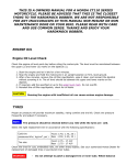
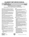
WCHE019 ONLY
)$1
767$7
%/.
%/.
%/.
%/.
&
62/(12,'
9$/9(
32:(5
&25'
*51<(/
%51
%/.
%/8
%/.
*51<(/
89086208
:,5(',$*5$0
- 20 -
© 2013 Pentair Equipment Protection
89087984
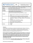
WCHE049, WCHE069, WCHE149
%/.
%51
%/8
0,
&$3
5('
5('
%/.
&
%/.
%/.
%51
%/8
*51<(/
767$7
32:(5
&25'
62/(12,'
9$/9(
89087061
:,5(',$*5$0
START-UP
Power the heat exchanger by turning on the circuit breaker or switch installed upstream from the unit. Fan(s) will
start up.
TEMPERATURE CONTROL
This device performs its function only when the cooling water is flowing, and its temperature is lower than the air
temperature in the cabinet. The bigger the temperature difference, the higher the cooling performance of the system.
PRELIMINARY CHECKS AFTER STARTING THE UNIT
Check that the air inside the cabinet is circulating as evenly as possible.
Check the unit while operating and verify the supply voltage maintains its rated values.
Verify water is flowing at the prescribed rate (when thermostat calls for cooling).
TURNING OFF THE UNIT
To turn off the unit, cut off the voltage to the system. The internal solenoid valve will automatically stop the water
flow.
89087984
© 2013 Pentair Equipment Protection
- 21 -
MAINTENANCE
Moving parts are totally automatic and highly reliable and ordinary maintenance is reduced to a minimum. This
maintenance, however, must be performed at the prescribed intervals.
Failure to perform maintenance compromises heat exchanger operation and durability and invalidates guarantee
coverage.
PREVENTATIVE MAINTENANCE SCHEDULE
TWICE A YEAR
Check that the heat exchange bank and fan protection grilles are clean and that dirt does not
prevent the passage of air.
Verify there are no abnormal noises during operation.
ANNUALLY
Check that fan motors and other components do not show abnormal vibrations or show signs of
overheating.
Check that water passage through the pipelines is not clogged by dirt.
REPLACEMENT OF COMPONENTS
We recommend replacing fans every 40,000 operating hours (with mean temperature of 40 C / 104
F).
HOW TO CLEAN THE UNIT
Open the unit by removing the panel fastening screws and clean it using compressed air.
To clean the heat exchange bank, blow compressed air in the direction opposite the flow of air that
normally passes through it (blow with compressed air at pressures not exceeding 60 psi / 4 bar).
Clean the pipelines inside the heat exchange coil by circulating clean water with detergent
designed to eliminate scale.
The detergent must not contain substances that can corrode copper.
WARNING
Use of an unsuitable detergent could cause damage to the heat
exchanger. Do not use acid or caustic substances to clean any
part of the exchanger
INACTIVITY
There is no problem as long as the liquid is expelled from the heat exchanger circuits and the
pipelines are sealed.
- 22 -
© 2013 Pentair Equipment Protection
89087984
INFORMATION ON RESIDUAL HAZARDS AND EMERGENCY SITUATIONS
This unit has been designed to minimize any dangerous situations. Such situations arise mainly from an improper
use of the product and the failure to comply with installation, use and maintenance standards. This information
must be made known to all personnel operating this unit and in the proximity thereof.
GENERAL SAFETY PROVISIONS
All personnel responsible for testing, operating and servicing this unit, must be familiar with the
following safety provisions:
•
•
•
•
•
•
•
•
•
•
Hazard tags and notices must be readily visible in any potential hazardous areas
A monitoring service must be arranged in such hazardous areas
Supervisors must keep in constant touch with monitors
Transit areas, doorways and stairways, in proximity of the unit must be kept clear
Emergency exits must be kept clear at all times.
Slippery areas which are hazardous to personnel must be covered with anti-slip material.
For any specific activity, specific tools and procedures must be used.
Testing tools and equipment must be kept in good working order.
Personnel must have a thorough knowledge of methods and procedures used in the event of a fire (make fire
extinguishers readily accessible).
The following steps must be taken at the outbreak of a fire:
»» turn off the electric power supply from the part affected by fire
»» increase ventilation capacity to evacuate combustion gases
»» inform appropriate department.
HAZARDS ARISING FROM THE PRODUCT COMING INTO CONTACT WITH THINGS OR
PERSONS
•
•
•
Danger point 1a) is fan movement. The fan’s protective grille prevents passage of bodies with dimensions greater
than
0.4 in / 10 mm.
Danger point 1b) is accidental contact with the heat exchange bank which has aluminum fins with sharp cutting
edges.
Danger point 1c) is contact with sharp sheetmetal edges. Gloves should be worn and caution taken to avoid injury.
SAFETY STANDARDS FOR ELECTRICAL EQUIPMENT
INTRODUCTION
Causes of electrical hazards are well known and prevention is not difficult provided constant care
is applied.
In order to reduce such risks, operators must be informed of potential hazards and trained on the
use of safety procedures.
TASKS ASSIGNED TO OFFICERS-IN-CHARGE
Officers-in-charge must be informed of any potential hazards existing in the system and must monitor
electric equipment operators. This monitoring function involves identifying possible dangerous situations
and investigating problems encountered by personnel during maintenance procedures.
Each faulty part must be repaired or replaced immediately.
An officer-in-charge must enforce the use of safety procedures without tolerating or accepting any
shortcuts, as this can cause harm to persons and equipment.
HIGH VOLTAGE
Contact with high voltage circuits can cause burns, shock, loss of consciousness and even the victim’s
electrocution.
This may happen due to lack of awareness of the dangers associated with the use of electrical equipment.
The injury suffered by the human body depends on the amount of power as well as on the duration and
path followed by the current inside the body.
89087984
© 2013 Pentair Equipment Protection
- 23 -
SAFETY STANDARDS TO COMPLY WITH WHEN THE EQUIPMENT IS TURNED OFF
Before servicing the equipment, disconnect all circuits.
Make sure that no voltage whatsoever is present in the circuit.
Clean and dry the whole area.
Remove pins, rings, brackets or any accessories which may hinder operations or turn into a potential
electrical conductor.
Ground discharge to earth or short circuit the capacitor terminals connected with the deactivated circuit.
Remove the fuses only after the circuit has been deactivated.
SAFETY STANDARDS TO COMPLY WITH WHEN SERVICING LIVE EQUIPMENT
Add the following provisions to those under items 2, 3 and 4 above:
•
•
•
•
•
•
•
•
Personnel must never operate alone
If possible, use only one hand to perform work required
Check wires and instruments regularly
Use only approved procedures to bypass the interlocks
Ensure that operators are familiar with equipment parts and maintenance procedures, before servicing the unit
Use a pair of safety gloves
Open all contacts which feed power to the equipment before measuring resistance levels; verify there is no high
voltage in the low voltage circuits
Do not use magnetic tools RDXC in the proximity of strong magnetic fields
SAFETY STANDARDS TO COMPLY WITH WHEN SERVICING THE UNIT
If continuous duty is not required, the system must be turned off. Before commencing work, the following
is required:
•
•
•
•
•
Check that the maintenance technician is not carrying any objects which may act as conductors
Inspect the work area to make sure the floor is clean and dry
Check work tools. They must be suitable for their designated task and in good working order to ensure safe
maintenance operations
Check that all gauges are regularly calibrated
Check servicing procedures before commencing work by inspecting the wiring diagram and visualizing the system
structure
When carrying out electrical maintenance operations, the following is required:
•
•
•
•
•
The maintenance technician must be familiar with high voltage circuits
No resistance measurements are to be carried out on live circuits
Use only one hand to take measurements on live circuits
Earth all instrument terminals before taking measurements on live circuits
The above recommendations must be strictly adhered to
Maintenance operations shall be deemed to have been completed only when all parts have been reinstalled and the product has regained its original appearance
FIRE HAZARDS
No direct danger
TOXIC SUBSTANCES
None
DANGERS ARISING FROM FLUIDS
Danger only arises if the fluid is dispersed in the installation site. This creates danger for passage by
persons.
The same danger exists if condensate, generated by the unit, is not collected and discharged to a suitable
drain.
- 24 -
© 2013 Pentair Equipment Protection
89087984
DISASSEMBLING THE UNIT
WARNING
Dismantling of this unit must always be done by expert personnel.
Make sure the electrical supply to the unit is interrupted before
starting to dismantle it.
Note: The heat exchanger will hold water and could be severely damaged by freezing
temperatures.
89087984
© 2013 Pentair Equipment Protection
- 25 -
TROUBLE SHOOTING
SYMPTOMS AND POSSIBLE CAUSES:
SYMPTOM
POSSIBLE CAUSE
No voltage to the unit
Check that the power cord is plugged in securely
No part is working
Check the main voltage and make sure that the doors,
switches and circuit breakers are closed
Obstructed fan blades
- Verify fan spins freely
Fan faulty
- Change the fan
Fan is not working
Fan capacitor (if any) faulty
- Change the capacitor
Thermostat is set too high
- Adjust thermostat to a lower temperature.
The fans are working but no heat exchange takes place
Insufficient cooling fluid.
- Check that the flow rate corresponds to the prescribed flow
rate on the unit nameplate
- Thermostat faulty
-Solenoid valve faulty
Water temperature too high
- Check the water temperature
Obstructed airflow in cabinet
- Verify sufficient airflow
For additional technical information, contact Pentair Equipment Protection at 800-896-2665.
- 26 -
© 2013 Pentair Equipment Protection
89087984
REPLACEMENT PARTS
WCHE019
Item
115 V Part Numbers
230 V Part Numbers
Air Mover
26037
26032
Thermostat
26034
26034
Solenoid Valve
26038
26033
3/8 inch G-NPT Adapter Valve
26035
26035
Gasket (1 required)
26036
26036
Item
115 V Part Numbers
230 V Part Numbers
Air Mover
26045
26041
Thermostat
26034
26034
Solenoid Valve
26046
26042
Capacitor
26047
26043
1/2 inch G-NPT Adapter Valve
26044
26044
Gasket (2 required)
26036
26036
Item
115 V Part Numbers
230 V Part Numbers
Air Mover
26051
26048
Thermostat
26034
26034
Solenoid Valve
26046
26042
Capacitor
26052
26043
1/2 inch G-NPT Adapter Valve
26044
26044
Gasket (2 required)
26036
26036
Item
115 V Part Numbers
230 V Part Numbers
Air Mover
26055
26053
Thermostat
26034
26034
Solenoid Valve
26046
26042
Capacitor
26054
26054
1/2 inch G-NPT Adapter Valve
26044
26044
Gasket (2 required)
26036
26036
WCHE049
WCHE069
WCHE149
89087984
© 2013 Pentair Equipment Protection
- 27 -
NOTES
- 28 -
© 2013 Pentair Equipment Protection
89087984
NOTES
89087984
© 2013 Pentair Equipment Protection
- 29 -
WARRANTY
Pentair Equipment Protection warrants that the Goods manufactured by Pentair Equipment Protection
will be free from defects in material and workmanship for a period of one (1) year from the date of
shipment by Pentair Equipment Protection, subject to the following conditions and exclusions:
A. Conditions. All Goods must be installed and operated according to the following specifications:
1. Maximum voltage variation no greater than plus or minus 10% of nameplate nominal rating;
2. Maximum frequency variation no greater than plus or minus 3 Hz. of nameplate nominal rating;
3. Must not exceed minimum and maximum stated temperatures on the nameplate;
4. Must not exceed (BTU/Hr) rating, including any heat sink as indicated on the nameplate;
5. Refrigerant bearing Goods must not be restarted for a period of one (1) minute after intentional or
accidental shut-off;
6. The filters (if applicable) must be cleaned regularly;
7. The Goods and any parts thereof must not be modified, unless prior written authorization is
received from Pentair Equipment Protection; and
8. All Goods must be installed and grounded in accordance with all relevant electrical and safety
codes, as well as the National Electric Code and OSHA rules and regulations.
9. All Goods must be installed in a stationery application, free of vibration.
A violation of any one of these conditions shall render the warranty hereunder void and of no effect.
B. Exclusions. This warranty shall be void if product is misapplied in any way or:
1. Buyer specified product is inappropriate for system or environment in which it is operating.
2. Pentair Equipment Protection product modified in any way without prior written authorization from
Pentair Equipment Protection.
3. Removal or modification of Pentair Equipment Protection label affixed to product without written
Pentair Equipment Protection approval.
Pentair Equipment Protection must be notified of a claim in writing not later than fourteen (14) days from
the date when Buyer has become aware of such occurrence, or where the defect is such that it may cause
damage, immediately, such notice containing a description of how the defect manifests itself. Failure to
provide such prompt notice to Pentair Equipment Protection shall result in forfeiture of Buyer’s rights
under this warranty.
In the event of a warranty claim, Buyer is to return defective goods to Pentair Equipment Protection in
accordance with Pentair Equipment Protection Return Policy. Warranty period for repaired goods remains
at 1 year from shipment of original goods. Pentair Equipment Protection sole obligation to Buyer under
this warranty will be, at Pentair Equipment Protection option:
A. Repair or replace Pentair Equipment Protection products or parts found to be defective in material or
workmanship.
B. Issue credit for the purchase price paid by Buyer relating to such defective Goods or part.
THIS WARRANTY CONSTITUTES THE ENTIRE WARRANTY WITH RESPECT TO THE GOODS AND IS IN
LIEU OF ALL OTHER WARRANTIES, EXPRESSED OR IMPLIED, INCLUDING ANY IMPLIED WARRANTY OF
MERCHANTABILITY AND IMPLIED WARRANTY OF FITNESS FOR A PARTICULAR PURPOSE.
RETURN AND REPAIR POLICY
Pentair Equipment Protection products that: (i) are made to order, (ii) have been modified by Buyer, (ii)
have special finishes, or (iv) are determined by Pentair Equipment Protection to constitute “custom”
products that cannot be returned to stock or resold to other Buyers, will not be accepted for return by
Pentair Equipment Protection.
All returns require a Return Material Authorization number (RMA #), regardless of reason for return,
whether it be for warranty or out of warranty repair. Returns without an RMA # will be refused by our
Receiving Department. An RMA # is valid for 60 days.
A. An RMA # will be issued by our Repair Department in Anoka, MN at 866-545-5252. Buyer should have
following information available at time of RMA request:
1. Complete Model Number, Serial Number and description of damaged unit being returned.
2. Original Buyer Purchase Order number and date product was received by Buyer.
3. Quantity to be returned and a brief description of failure for each unit, if different.
- 30 -
© 2013 Pentair Equipment Protection
89087984
B.
C.
D.
E.
F.
G.
4. Contact information of Buyer that must include: name of company, billing and shipping address,
phone, number, fax number, freight carrier and the name and phone number of a Buyer contact
who can elaborate on the claimed defect in detail.
5. Buyer must provide a Repair Purchase Order number for both warranty and out of warranty
repairs. The PO will not exceed 50% of a new unit. Buyer will be notified of repair charges that
exceed approved PO amount.
All returns to Pentair Equipment Protection must be securely packed, using original cartons if
possible. All returns must have the RMA number visible on the outside of the carton. Pentair
Equipment Protection is not responsible for material damaged in transit. Any refrigerant-bearing
Goods must be shipped upright for return.
Shipping cost for all non-warranty repairs is the responsibility of the sender and must be shipped
prepaid. Shipping costs for all warranty related repairs will be covered by Pentair Equipment
Protection provided the goods are returned using a Pentair Equipment Protection approved carrier.
If after diagnoses the product is determined by Pentair Equipment Protection not be covered under
warranty, Buyer will be responsible for all shipping charges and will be billed accordingly.
Non-warranty repairs are subject to a $75 minimum analysis fee. Analysis fee will be waived if Buyer
approves repair work. If approval is not received within 30 days, material will be scrapped and all
shipping expenses and corresponding analysis fees will be billed to Buyer.
At Buyer’s request, Failure Analysis can be provided by Pentair Equipment Protection for warrantable
goods at no charge. Failure analysis for non-warranty repairs are subject to a $100 per hour
Engineering charge plus any other incurred testing costs.
All returned merchandise must be sent to the following address: Pentair Equipment Protection, 2100
Hoffman Way, Anoka, MN 55303-1745.
Credit for accepted returns shall be at the original selling price or the current selling price, whichever
is lower, less the restocking charge indicated as follows:
1. Within 60 days of invoice date - 20% of applicable selling price.
2. Within 61-120 days of invoice date - 30% of applicable selling price.
3. Within 121-180 days of invoice date - 40% of applicable selling price.
4. Beyond 180 days - subject to individual review by Pentair Equipment Protection.
If product being returned for credit requires repair or modification, the cost of any labor or material
necessary to bring product into saleable condition will be deducted from credit. Buyer may not take credit
against returns without prior written Pentair Equipment Protection approval.
LIMITATION OF LIABILITY
Pentair Equipment Protection WILL NOT BE LIABLE UNDER ANY CIRCUMSTANCES FOR ANY
INCIDENTAL, CONSEQUENTIAL OR SPECIAL DAMAGES, INCLUDING WITHOUT LIMITATION ANY LOST
PROFITS OR LABOR COSTS, ARISING FROM THE SALE, USE OR INSTALLATION OF THE GOODS, FROM
THE GOODS BEING INCORPORATED INTO OR BECOMING A COMPONENT OF ANOTHER PRODUCT, FROM
ANY BREACH OF THIS AGREEMENT OR FROM ANY OTHER CAUSE WHATSOEVER, WHETHER BASED ON
WARRANTY (EXPRESSED OR IMPLIED) OR OTHERWISE BASED ON CONTRACT, OR ON TORT OR OTHER
THEORY OF LIABILITY, AND REGARDLESS OF ANY ADVICE OR REPRESENTATIONS THAT MAY HAVE
BEEN RENDERED BY Pentair Equipment Protection CONCERNING THE SALE, USE OR INSTALLATION OF
THE GOODS
89087984
© 2013 Pentair Equipment Protection
- 31 -
Pentair Equipment Protection
2100 Hoffman Way
Minneapolis, MN 55303 USA
+1.763.422.2211
+1.763.576.3200
PentairEquipmentProtection.com
Rev. G
© 2013 Pentair Equipment Protection
P/N 89087983
89087984