1
Support Note 316, Revision A
NanoLithography
316.1 Overview
This support note details NanoLithography theory, NanoScript™ syntax for performing lithography
commands and procedures to test, build and run NanoLithography programs.
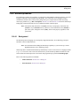
Refer to the following sections for using your NanoLithography Package:
•
New NanoLithography Package: Section 316.2 on Page 2
•
Package Contents: Section 316.2.1 on Page 2
•
Terms and Definitions: Section 316.2.2 on Page 3
•
NanoLithography Theory: Section 316.3 on Page 5
•
Procedures to Perform NanoLithography: Section 316.4 on Page 8
•
Testing Your System [LithoHelloWorld.dll]: Section 316.4.2 on Page 9
•
Testing Your System [Diamond.dll]: Section 316.4.3 on Page 15
•
Modifying a Lithography Program: Section 316.4.4 on Page 19
•
Writing a New Lithography Program: Section 316.4.5 on Page 24
•
Exporting Older Programs into Version 5.12 or Later: Section 316.4.6 on Page 30
•
Performance Tips: Section 316.4.7 on Page 31
•
Sample Programs Overview: Section 316.5 on Page 33
•
NanoScript Macros: Section 316.6 on Page 37
•
Litho.h Functions: Section 316.7 on Page 38
•
Gui.h Functions: Section 316.8 on Page 46
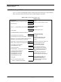
Document Revision History: NanoLithographyy
Revision
A
Date
11-12-01
Section(s) Affected
New Release
© Digital Instruments Veeco Metrology Group, 2001
112 Robin Hill Road
Santa Barbara, CA 93117
805.967.1400
Reference
DRF 0426
Approval
C. Fitzgerald
L. Fukunaga
Part Number: 013-316-000
New NanoLithography Package
Package Contents
316.2 New NanoLithography Package
Scanning Probe Microscope (SPM) Lithography or NanoLithography functions are now available in
an optional package. The NanoLithography enhancements include:
•
Building custom lithography programs
•
Building (and debugging) larger programs to control the NanoScope.
The new package includes an industry standard compiler as well as three sample templates to
successfully test and run your Lithography programs. The program files are in the form of dynamiclink library (DLL) files for loading in to the NanoScope system software.
316.2.1
Package Contents
The optional NanoLithography package includes:
•
This Support Note [New]—Detailing NanoLithography theory, Macro language
commands, procedures and sample programs for use as templates.
•
Compiler [New]—An industry standard, C/C++ compiler to build dynamic link
libraries (DLL).
Note: The current compiler is Microsoft ® Visual C++ Standard Edition™, Version 6.0.
2
•
gui.h [New]—File of the graphical user interface (GUI) functions to add dialog boxes,
messages and notes, etc. for user input.
•
litho.h—File of Lithography function declarations (i.e., functionally the same as previous
versions) to run the basic lithographic functions.
•
z.lib—Library of NanoScope functions (i.e., linked in to your program).
•
Sample Programs—Three sample programs to test, modify and write Lithography
programs.
NanoLithography
Rev. A
New NanoLithography Package
Terms and Definitions
316.2.2
Terms and Definitions
In order to understand the processes detailed in this support note, it may be helpful to become familiar
with specific terms:
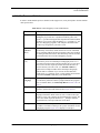
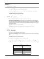
Table 316.2a NanoLithography Terms and Definitions
Rev. A
Term
Definition
Compiler
The compiler (i.e., Visual C++ Studio compiler) is responsible for
building the project files in to a dynamic link library (DLL) file.
Visual C++ provides an Integrated Development Environment (IDE)
that allows you to write, build, and debug C/C++ programs (i.e., the
basis for Lithography programs). The compiler environment also
provides easy navigation of your source code.
Dynamic Link
Libraries
(DLL)
A dynamic-link library (DLL) is an executable file that acts as a
shared library of functions, which contain one or more commands
that are compiled, linked, and stored separately. DLLs also facilitate
the sharing of data and resources. The NanoScope software searches
and loads the DLL file to run the Lithography program.
Header Files
(*.h)
Header Files or "Include Files" contain the C/C++ declarations of
the functions you use for NanoScript or lithography. In the C/C++
environment, functions must be declared before they are used. Your
macro source file must explicitly include the header file that contains the function you want to call. (ex. "#include <litho.h>").
Litho.h in this example includes all the NanoScope lithography
functions that are available. If you want to call GUI functions,
include gui.h. (ex. "#include <gui.h>") These header files should be
located in the Include subdirectory in the SPM folder.
NanoScript
Language
NanoScript is a fully C-capable language extension that includes
over 200 library functions written by Digital Instruments’ programmers. For further details, see NanoScript Macros: Section 316.6 on
Page 37.
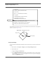
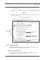
Project
A project is similar to a folder. It consists of a set of files, which act
together to perform the Litho functions (See Figure 316.2a).
Source Files
In the Microsoft Project files, the source files include the NanoScript
Language information. When selected, code is visible in the right
window to verify, edit or modify the NanoLithography settings. The
source files contain exported functions (i.e., _declspec modifier),
internal functions, and output functions for the DLL.
Workspace
A window in the C++ compiler that consists of a set of objects, files
and folders. The folders contain specific project information for the
Lithography program. Figure 316.2a displays a workspace.
NanoLithography
3
New NanoLithography Package
Terms and Definitions
Term
Definition
Z.lib
A library of NanoScope functions (i.e., linked in to your program).
This import library (Z.LIB) file contains information that the link
(Project > Settings > Link tab) needs for resolving external references to exported DLL functions. The purpose is for the system to
locate the loaded DLL file and then export the NanoScope Lithography functions in real time mode.
For example, to call the AskOK function, you must link the code
with the import library Z.LIB. The reason is that AskOK resides in
the NanoScope system DLL. The file Z.LIB is the import library
used to resolve the call to apply the AskOK command in your code.
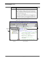
Figure 316.2a Workspace and Project Files
*.h
Files
7216
Workspace
File View
4
Source File View
NanoLithography
Rev. A
NanoLithography Theory
Mechanical Properties
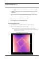
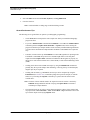
316.3 NanoLithography Theory
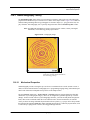
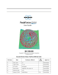
The NanoLithography feature allows for performing movements in nano scale areas. The lithography
programs direct the microscope to inscribe or move items on the sample surface. Figure 316.3a shows an
STM (Scanning Tunneling Microscopy) lithograph of concentric shapes (i.e., polygon and circles) on a
poly carbonate. This lithography uses a specially designed scanner called a Closed Loop XY scanner.
Note: For additional information on using a Closed Loop XY scanner, contact your Digital
Instruments, Veeco Metrology Group representative.
7244
Figure 316.3a Lithography Image
Image is Courtesy of Debra Cook,
Application Scientist, Digital Instruments,
Veeco Metrology Group
316.3.1
Mechanical Properties
NanoLithography consists of using the tip as an electro or mechanical tool to scribe (indent or create a
ditch) on various material surfaces. Lithography uses C programming language along with NanoScript™
macro Litho functions to manipulate the tip relative to the sample surface.
The area Scan size (Real Time > Scan Controls > Scan Size parameter setting) defines the allowable
dimensions of your Lithographic image(s). There are no safeguards to guarantee against tip or surface
damage. To allow for full control of your Lithography functions, you must carefully define the physical
limits, then execute commands which do not exceed those limits. In selected instances, the software
warns you when executing commands beyond limits in the X-Y plane (e.g., trying to move the tip outside
the bounds of the maximum Scan size). Most commands assume the tip is within its physical limits, such
as when the tip is plunged into a surface, then dragged through material.
Rev. A
NanoLithography
5
NanoLithography Theory
Mechanical Properties
Applications
Lithography programs may be run in Scanning Tunneling Microscopy (STM), Contact Atomic Force
Microscopy (AFM), and TappingMode AFM. Each mode produces its own unique results.
STM. Scanning Tunneling Microscopy (STM) can be used to modify surfaces at the nano scale level.
By applying voltage pulses (e.g., see LithoPulse: Section 316.7.12 on Page 42) of varying magnitude
and frequency, structures can be created. By programming the tip to move in a pre-determined fashion,
you can also indent the surface.
Selecting an SPM Mode and Probe for Nanolithography
There are many SPM techniques for modifying a surface using Nanolithography. Some techniques rely
on mechanical (contact) interactions between the probe and the sample; others rely on an electrical
current flowing between the probe and the sample; yet others use magnetic interactions; and the list
grows with every user. The choice of the SPM technique and probe depends on the sample and the
desired results.
NanoLithography is a rapidly evolving field of research. The best source of information on the choice
of probes and techniques is peer-reviewed technical literature and other technical journals and
websites.
Note: For a sample list of the probes available from Digital Instruments,Veeco Metrology
Group, see also The Command Reference Manual Version 5.12B, Appendix A - Tip
Selection Guide as well as your system manuals.
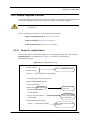
Example: Scribing with the Lithography Program
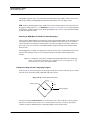
In this Sample #2: Diamond program, the tip plunges 20 nm into the surface after moving 10 µm from
the center of the scan field creating a diamond with sides of 20µm.
Figure 316.3b LithoTranslate Movement
10 µm
Image center
10 µm
Start Lithography
The macro command, LithoTranslate, moves the tip from center, then to the three o’clock position,
then moves counterclockwise to the twelve o’clock position at a set rate of 20 µm/s. The tip then
continues to draw the additional sides of the diamond shape on the sample surface.
6
NanoLithography
Rev. A
NanoLithography Theory
Mechanical Properties
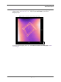
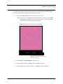
Figure 316.3c shows a diamond-shaped lithography pattern on a poly carbonate sample using a
standard scanner. See Section 316.5.2 (i.e., sample program: Diamond.dll) to perform this
lithography shape.
7246
Figure 316.3c Diamond-shaped Lithography Image
To perform NanoLithography, please refer to Procedures to Perform NanoLithography: Section
316.4 on Page 8.
Rev. A
NanoLithography
7
Procedures to Perform NanoLithography
What You Will Need
316.4 Procedures to Perform NanoLithography
This section details the setup and load of a sample lithography program provided with your
NanoLithography package. The objective is to practice the procedures thoroughly in order to understand
additional NanoLithography program procedures.
Refer to the following sections to perform NanoLithography on your NanoScope system:
316.4.1
•
What You Will Need: Section 316.4.1 on Page 8
•
Testing Your System [LithoHelloWorld.dll]: Section 316.4.2 on Page 9
•
Testing Your System [Diamond.dll]: Section 316.4.3 on Page 15
•
Modifying a Lithography Program: Section 316.4.4 on Page 19
•
Writing a New Lithography Program: Section 316.4.5 on Page 24
•
Exporting Older Programs into Version 5.12 or Later: Section 316.4.6 on Page 30
•
Performance Tips: Section 316.4.7 on Page 31
What You Will Need
To perform Lithography on the NanoScope, you must have the following components:
•
Microsoft Visual C++ Compiler (provided with your NanoLithography option)
•
Internet Explorer ™ browser 4.0 or above is necessary to install the Visual C++ compiler.
•
NanoScope Software (5.12 or above)
Note: Older versions of the NanoScope software require additional functions to run
NanoLithography in the manner detailed in this support note. For exporting older
Lithography files for use in the 5.12 NanoScope software, see Exporting Older
Programs into Version 5.12 or Later: Section 316.4.6 on Page 30.
•
NanoLithography Program files (e.g., litho.h, z.lib, gui.h, sysdefs.h and three
sample programs)
In general, NanoLithography includes the following abbreviated steps:
1. Perform the necessary steps for placing all files in the SPM directory.
2. Verify, edit or modify the lithography program in the C++ compiler source files.
3. Build the DLL file in the C++ compiler.
4. Engage the tip on the surface and obtain an image in the NanoScope.
5. Determine the lithography site on the sample surface.
8
NanoLithography
Rev. A
Procedures to Perform NanoLithography
Testing Your System [LithoHelloWorld.dll]
6. Load and run the macro lithography program (DLL).
7. Continue to image the site.
8. Capture the lithographic image.
316.4.2
Testing Your System [LithoHelloWorld.dll]
The NanoLithography package includes one sample to test the features in using the C++ compiler and
NanoScript interface. This section details the procedures to run the sample program, lithoHelloWorld.
This program loads a dialog box that displays the phrase, “Hello World!”.
Note: The LithoHelloWorld test sample does not require hardware to load and run. Its purpose
is to test the procedures and ability to load a DLL file in the NanoScope. For testing a
simple program that uses the hardware, see Testing Your System [Diamond.dll]: Section
316.4.3 on Page 15.
Locate the Necessary Lithography Files
When running the macro files, the program looks in specific directories for running the commands.
Complete the following procedures to verify that the files are in the correct directory structure.
1. Verify or place the sample program (e.g., LithoHelloWorld) file in your SPM directory. This folder,
containing the C++ source files, should be located in the same directory as your NanoScope
software executable file (i.e., z.exe).
2. Locate or place the litho.h, gui.h, sysdefs.h header files in your SPM/Include directory.
Note: The Include directory must be at the same level as your Z.exe SPM executable file.
3. Verify that the z.lib file is in the SPM directory. This folder should be located in the same directory
as your Z.exe NanoScope software executable file.
4. Open a Workspace in The Microsoft Visual C++
5. Locate the sample program folder (e.g., LithoHelloWorld) and open the folder to display the list of
files.
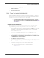
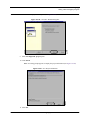
6. Double-click on the workspace file (i.e., the file with an *.dsw file extension).
Note: This will open the Microsoft Visual C++ compiler and workspace
(See Figure 316.4a).
Rev. A
NanoLithography
9
Procedures to Perform NanoLithography
Testing Your System [LithoHelloWorld.dll]
Figure 316.4a C++ Compiler File View
7215
Source Code from the
lithoHelloWorld.cpp File
Workspace and
List of Project Files
Note: If the source code is not open in the client window, expand the Source files in the
workspace and double-click the *.cpp file to display the source code information.
Note: For specific details of the source code in this sample, see Sample #1: LithoHelloWorld:
Section 316.5.1 on Page 33.
Verify Project Settings
In order for the files to link and place output files in the correct directories, you must verify the project
settings.
1. In the Visual C++ menu bar, select Project > Settings to open the Project Settings dialog box.
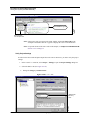
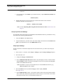
2. Select the C/C++ tab (See Figure 316.4b).
a. Change the Category to PREPROCESSOR.
Figure 316.4b C/C++ Tab
7213
SPM/Include
Directory
Path
10
NanoLithography
Rev. A
Procedures to Perform NanoLithography
Testing Your System [LithoHelloWorld.dll]
b. In the Additional Include Directories window, the path displays two dots, a backward slash and
the include file name. This allows the program to look one level up from the lithography folders
in the SPM/Include directory.
Note: Remember to verify the correct header files are in the SPM/Include directory (e.g.,
litho.h and gui.h for this example).
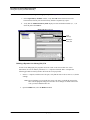
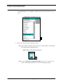
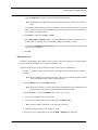
3. Select the Link tab and verify that the Category window displays GENERAL
(See Figure 316.4c).
Figure 316.4c Project Properties Dialog Box
7212
Link
Tab
a. In the Output file name window, verify that the display reads two dots, a backward slash and the
output FILE NAME (e.g.,..\lithoHelloWorld.dll).
Note: This notation places the file at one level up (or out) from the project folder and allows for
this DLL file to be at the Z.exe, or SPM executable file level.
b. In the Output file name window, you may replace the two dots and backward slash with the
exact location of the directory structure (e.g., D:/SPM/LithoHelloWorld.dll).
Note: If the file name already exists, the new DLL file will overwrite the old file automatically.
If the file name does not exist, the final DLL file is added to the SPM directory.
Rev. A
NanoLithography
11
Procedures to Perform NanoLithography
Testing Your System [LithoHelloWorld.dll]
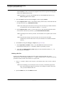
4. In the Link tab, change the Category to Input (See Figure 316.4d).
a. In the Object/library modules window, verify that z.lib follows that last item in the
horizontal list of library files and each library module is separated by a space.
b. Verify that the Additional Library Path displays two dots and backward slash (i.e., ..\) to
direct the path to the z.lib file.
Figure 316.4d Link Tab
Input
Category
7214
NanoScope
Library File
Building a Dynamic Link Library (DLL) File
In order to run lithography, the programs need to be “built” in the form of DLL files. Veeco
Instruments, Inc. uses an industry standard, C/C++ compiler to build the DLLs. Complete the
following procedures to build your DLL file from the set of project files.
1. In the C++ compiler, with the source file open, verify that the source code is correct (i.e., edit the
settings).
Note: Prior to building you can modify the source code. Once you build the program, the
DLL locks all program settings in to the DLL file. If changes are made to the source
code, you must rebuild the DLL file.
2. Open the Build menu, select the Build command.
12
NanoLithography
Rev. A
Procedures to Perform NanoLithography
Testing Your System [LithoHelloWorld.dll]
Debugging the Program
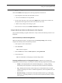
Verify that the Build window displays file code being compiled into the DLL file.
1. Upon completion of the build, check the number of errors. (See Figure 316.4e).
7217
Figure 316.4e Build Window
a. For a successful build, the error log shows 0.
2. If errors exist in the source code, scroll up in the Build window, double click to read the error
message and an arrow appears in the source code where the error exists.
a. Make necessary changes in the setting or syntax.
3. Once the errors are fixed, select the Build > Rebuild menu command.
Using the NanoScope Software and Running Your Litho Programs
Once you build and debug a program, the DLL file is ready to load in the NanoScope software to run
lithography. In lithoHelloWorld, hardware is not necessary to test the macro load features.
Open the NanoScope Debug Window
While in the NanoScope software, it is helpful to have the NanoScope Debug window showing.
Complete the following while in the NanoScope software:
1. Click on the Control Monitor and hit Ctrl-Alt-D.
2. Select the Filter menu and check Litho, SayError, and LogAllChecked.
3. Close the filter box.
Note: You should then see debug msgs in the black debug window.
Run the Lithography Macro (DLL)
1. Open the Real Time mode operations.
2. Open the DI menu and select the NanoScript command.
Rev. A
NanoLithography
13
Procedures to Perform NanoLithography
Testing Your System [LithoHelloWorld.dll]
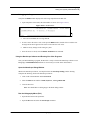
3. In the NanoScript screen, select Macro > Load to access the list of DLL files (See Figure
316.4f).
7228
Figure 316.4f Lithography DLL Files
4. Browse to select the DLL file to load and click OK.
Note: In this sample, a dialog box appears on the screen with the phrase, “Hello World!”
for testing the Macro loading procedures.
7226
Figure 316.4g LithoHelloWorld Dialog Box
Note: See also, Testing Your System [Diamond.dll]: Section 316.4.3 on Page 15 for
details on interfacing with hardware to test your Lithography programs.
14
NanoLithography
Rev. A
Procedures to Perform NanoLithography
Testing Your System [Diamond.dll]
316.4.3
Testing Your System [Diamond.dll]
The NanoLithography package includes one sample to test the features in using the C++ compiler
and NanoScript interface. This section details the procedures to run the sample program, Diamond.
This program loads a program that scribes a diamond shape on the sample surface.
Note: This test sample requires hardware to load and run. Its purpose is to test the
procedures and ability to load a DLL file in the NanoScope and run the system. For
testing a simple program that does not require the hardware, see Testing Your
System [LithoHelloWorld.dll]: Section 316.4.2 on Page 9.
Locate the Necessary Lithography Files
When running the macro files, the program looks in specific directories for running the commands.
Complete the following procedures to verify that the files are in the correct directory structure.
1. Verify or place the sample program (e.g., Diamond) file in your SPM directory. This folder,
containing the C++ source files, should be located in the same directory as your Z.exe
NanoScope software executable file.
2. Locate or place the header files (e.g., litho.h, gui.h, sysdefs.h) in your SPM/Include
directory.
Note: The Include directory must be at the same level as your Z.exe SPM executable file.
3. Verify that the z.lib file is in the SPM directory. This folder should be located in the same
directory as your Z.exe NanoScope software executable file.
4. Open a Workspace in The Microsoft Visual C++
5. Locate the sample program folder (e.g.,Diamond) and open the folder to display the list of
files.
6. Double-click on the *.dsw workspace file.
Note: This will open the Microsoft Visual C++ compiler and workspace.
Verify Project Settings
In order for the files to link and place output files in the correct directories, you must verify the
project settings.
1. In the Visual C++ menu bar, select Project > Settings to open the Project Settings dialog
box.
2. Select the C/C++ tab.
a. Change that the Category to PREPROCESSOR.
Rev. A
NanoLithography
15
Procedures to Perform NanoLithography
Testing Your System [Diamond.dll]
b. In the Additional Include Directories window, the path displays two dots, a backward slash
and the include file name. This allows the program to look one level up from the lithography
folders in the SPM/Include directory.
Note: Remember to verify the correct header files are in the SPM/Include directory (e.g.,
litho.h and gui.h for this example).
3. Select the Link tab and check that the Category window displays GENERAL.
a. In the Output file name window, verify that the display reads two dots, a backward slash and
the output file name (e.g.,..\lithoHelloWorld.dll).
Note: This notation places the file at one level up (or out) from the project folder and allows
for this DLL file to be at the SPM executable (i.e., z.exe) level.
b. In the Output file name window, you may replace the two dots and backward slash with he
exact location of the directory structure (e.g., D:/SPM/LithoHelloWorld.dll).
Note: In naming the exact directory structure, forward slashes are acceptable to show the the
path.
Note: If the file name already exists, the new DLL file will overwrite the old file
automatically. If the file name does not exist, the final DLL file is added to the SPM
directory.
4. In the Link tab, change the Category to Input (See Figure 316.4d).
a. In the Object/library modules window, verify that z.lib follows that last item in the
horizontal list of library files (i.e., each library module is separated by a space).
b. Verify that the Additional Library Path displays two dots and backward slash (i.e., ..\) to
direct the path to the z.lib file.
Building a DLL File
In order to run lithography, the programs need to be “built” in the form of DLL files. Veeco
Instruments, Inc. uses an industry standard C/C++ compiler to build the DLLs. Complete the following
procedures to build your DLL file from the set of project files.
1. In the C++ compiler, with the source file open, verify that the source code is correct or edit the
settings.
Note: Prior to building you can modify the source code. Once you build the program, the
DLL locks all program settings in to the DLL file. If changes are made to the source
code, you must rebuild the DLL file.
2. Open the Build menu, select the Build command.
16
NanoLithography
Rev. A
Procedures to Perform NanoLithography
Testing Your System [Diamond.dll]
Debugging the Program
Check that the Build window displays file code being compiled in to the DLL file.
1. Upon completion of the build, check the number of errors.
a. For a successful build, the error log shows 0.
2. If errors exist in the source code, scroll up in the Build window, double click to read the error
message and an arrow appears in the source code where the error exists.
a. Make necessary changes in the setting or syntax.
3. Once the errors are fixed, select the Build > Rebuild menu command.
Using the NanoScope Software and Running Your Litho Programs
Once you build (and debug) a program, the DLL file is ready to load in the NanoScope software to run
lithography.
Open the NanoScope Software Debug Window
While in the NanoScope software, it is helpful to have the NanoScope Debug window showing.
Complete the following while in the NanoScope software:
1. Click anywhere on the Control Monitor.
2. Select Ctrl-Alt-D.
Note: A filter box appears.
3. Select the Filter menu and check Litho, SayError, and LogAllChecked.
4. Close the filter box.
Note: You should then see debug msgs in the black debug window.
Preparing the Microscope for a Lithography Program. In addition to the standard setup
requirements to run the microscope, it is necessary to verify the following components for desired results:
Rev. A
•
Sample—The sample depends on the method of lithography (i.e., scribing, indenting,
manipulating surface topography or oxidizing using advanced methods of Lithography).
•
Tip—Standard (Silicon Nitride) Contact mode tips are recommended on the two sample
templates requiring tip movement. On additional applications, follow the guidelines for your
desired results.
•
Real Time Settings—The Real Time control panels should reflect the type of lithography
desired (e.g., for scribing a diamond, you set the microscope profile and settings to Contact
mode operation).
NanoLithography
17
Procedures to Perform NanoLithography
Testing Your System [Diamond.dll]
1. Once the hardware and software components are set, open the Real Time mode operations.
Note: For this example, the NanoScript commands are accessed in Real Time or Offline
mode.
2. Verify that the sample is on the chuck (or stage) and complete the necessary steps to focus
surface and tip.
3. Set your microscope profile to Contact mode (Real time > Microscope > Profile > Contact
Mode).
Note: Set the mode to tapping for specific applications.
4. Engage the tip on the surface and view your imaging mode.
5. Open the DI menu and select the NanoScript command.
Run the Lithography Macro (DLL)
1. In the NanoScript screen, select Macro > Load to access the list of DLL files.
2. Browse to select the DIAMOND.DLL file to load and click OK.
Note: The imaging appears to stop while the debug window displays the program
instructions. Once the lithography is complete, a diamond shape is inscribed on the
sample surface (See Figure 316.4h).
7246
Figure 316.4h Diamond Test Program
18
NanoLithography
Rev. A
Procedures to Perform NanoLithography
Modifying a Lithography Program
316.4.4
Modifying a Lithography Program
In this example, the Diamond lithography program is modified by changing the tip X and Y movement
dimensions from 10µm to 5µm.
Locate the Necessary Lithography Files
When running the macro files, the program looks in specific directories for running the commands.
Complete the following procedures to verify that the files are in the correct directory structure.
1. Verify or place the sample program (e.g., LithoHelloWorld) folder in your SPM directory. This
file, containing the C++ source files, must be in a folder, which is in the same directory as your
Z.exe NanoScope software executable file.
2. Locate or place the litho.h, gui.h, sysdefs.h header files in your SPM/Include directory.
Note: The Include directory must be at the same level as your Z.exe SPM executable file.
3. Verify that the z.lib file is also in the same directory as your Z.exe NanoScope software executable
file.
Open a C++ Workspace
1. Locate the sample program folder (e.g. Diamond) and open the folder to display the list of files.
2. Double-click on the *.dsw workspace file.
Note: The Microsoft Visual C++ compiler and workspace opens (See Figure 316.4i).
3. Verify that the File View tab is selected to view the list of Source files.
Note: If the source code is not open in the client window, expand the Source files in the
workspace to display Diamond.cpp, double-click the Diamond.cpp file to display the
source code information (See Figure 316.4i).
Note: For details of the source code in this sample, see Sample #2: Diamond: Section 316.5.2.
Modify the Source File
In this example, the source code modification includes changing the tip travel distance from 10µm to
5µm in the X and Y direction.
1. In the line, double size = 10;// 10 um from center of diamond to point, change the 10 to 5 and
update the comment to your new specifications (See Figure 316.4i).
Note: This changes the tip travel distance in the X and Y direction from 10µm to 5µm. You may
also change the Scan size in the Scan Controls panel to suit the new dimensions. In this
example, the dimensions are lowered, so changing the Scan size is not necessary.
Rev. A
NanoLithography
19
Procedures to Perform NanoLithography
Modifying a Lithography Program
Figure 316.4i Modified Source Code
// diamond.cpp
// Example - Modifying a Lithography Program
#include <litho.h>
extern "C" __declspec(dllexport) int macroMain()
{
LITHO_BEGIN
LithoDisplayStatusBox();// display litho status box
LithoScan(false);// turn off scanning
LithoCenterXY();// move tip to center of field
Modification
double size = 5;// moves the tip from center of diamond 5 um in X and Y.
double rate = 20;// move the tip in X-Y at 20 um/s
double depth = -0.020;// push the tip in 20 nm to draw lines
double z_rate = 0.040;// move the tip down at 40 nm/s
The modification causes the tip to move to the center and then move outward to the 3-o’clock position
a distance of 5µm (See Figure 316.4j).
Figure 316.4j LithoTranslate Movement
5 µm
Image center
5 µm
Start Lithography
Verify Project Settings
In order for the files to link and place output files in the correct directories, you must verify the project
settings.
1. In the menu bar, select Project > Settings to open the Project Settings dialog box.
2. Select the C/C++ tab.
a. Change the Category to PREPROCESSOR.
b. In the Additional Include Directories window, the path displays two dots, a backward slash
and the include file name. This allows the program to look one level up from the lithography
folders in the SPM/Include directory.
20
NanoLithography
Rev. A
Procedures to Perform NanoLithography
Modifying a Lithography Program
Note: Remember to verify the correct header files are in the SPM/Include directory (e.g.,
litho.h and gui.h for this example).
3. Select the Link tab and verify that the Category window displays GENERAL.
a. In the Output file name window, verify that the display reads two dots, a backward slash and the
output file name (e.g.,..\DiamondGui.dll).
Note: This notation places the file at one level up (or out) from the project folder and allows for
this DLL file to be at the SPM executable (i.e., z.exe) level.
b. In the Output file name window, you may replace the two dots and backward slash with D:/
SPM/DiamondGui.dll.
Note: If the file name already exists, the new DLL file will overwrite the old file automatically.
If the file name does not exist, the final DLL file is added to the SPM directory.
4. In the Link tab, change the Category to Input (See Figure 316.4d).
a. In the Object/library modules window, verify that z.lib follows that last item in the horizontal
list of library files and each library module is separated by a space.
b. Verify that the Additional Library Path displays two dots and backward slash (i.e., ..\) to direct
the path to the z.lib file.
Building a DLL File
In order to run lithography, the programs need to be “built” in the form DLL files. Veeco Instruments, Inc.
uses an industry standard C/C++ compiler to build the DLLs.
Complete the following procedures to build your DLL file from the set of project files:
1. In the C++ compiler, with the source file open, verify that the source code is correct or edit the
settings.
Note: Prior to building you can modify the source code. Once you build the program, the DLL
locks all program settings in to the DLL file. If changes are made to the source code, you
must rebuild the DLL file.
2. Open the Build menu, select the Build command.
Debugging the Program
During a build, verify the project settings scroll through the code to build a DLL file. If syntax errors
occur in the program, the build will not be successful.
1. Check the number of errors in the Build window. (See Figure 316.4e).
a. For a successful build, the error log shows 0.
2. If errors exist in the source code, scroll up in the Build window, double click to read the error
message and an arrow appears in the source code where the error exists.
Rev. A
NanoLithography
21
Procedures to Perform NanoLithography
Modifying a Lithography Program
a. Make necessary changes in the setting or syntax.
3. Once the errors are fixed, select the Build > Rebuild menu command.
Open the NanoScope Software
Once you build and debug a program, the DLL file is ready to load in the NanoScope software to run a
lithography on the sample surface.
Open the NanoScope Debug Window
While in the NanoScope software, it is helpful to have the NanoScope Debug window showing.
Complete the following while in the NanoScope software:
1. Click on the Control Monitor and hit Ctrl-Alt-D.
2. Select the Filter menu and check Litho, SayError, and LogAllChecked.
3. Close the filter box.
Note: You should then see debug msgs in the black debug window.
Prepare the Microscope for a Lithography Program. In addition to the standard setup
requirements to run the microscope, it is necessary to verify the following components for desired
results:
•
Sample—The sample depends on the method of lithography (i.e., scribing, indenting,
manipulating surface topography or oxidizing using advanced methods of Lithography).
•
Tip—Standard (Silicon Nitride) Contact mode tips are recommended on the two sample
templates requiring tip movement. On additional applications, follow the guidelines for
your desired results.
•
Real Time Settings—The Real Time control panels should reflect the type of lithography
desired (e.g., for scribing a diamond, you set the microscope profile and settings to Contact
mode operation).
1. Once the hardware and software components are set, open the Real Time mode operations.
2. Open the DI menu and select the NanoScript command.
Run the Lithography Macro DLL
1. In the NanoScript screen, select Macro > Load to access the list of DLL files.
2. Browse to select the DLL file to load and click OK.
22
NanoLithography
Rev. A
Procedures to Perform NanoLithography
Modifying a Lithography Program
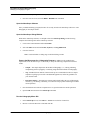
Note that in the image window, scanning appears to halt. This means that the Lithography program
is loading. If your debug window appears, the program instructions display as the Lithography
program is running. Upon completion, the real time scan continues.
3. View your new diamond shape on the surface (See Figure 316.4k).
Note: Figure 316.4k is a lithographic image captured using a Closed Loop XY scanner.
For additional information on a Closed Loop XY scanner, contact your Digital
Instruments, Veeco Metrology Group representative.
7247
Figure 316.4k Diamond-shaped Lithography Image
Image is Courtesy of Debra Cook,
Application Scientist, Digital Instruments,
Veeco Metrology Group
4. Select Capture > Capture Filename to name the file.
5. Select the CAPTURE button or Capture menu > Capture command.
6. View this image in offline mode to modify (e.g., Flatten) or analyze the image.
Rev. A
NanoLithography
23
Procedures to Perform NanoLithography
Writing a New Lithography Program
316.4.5
Writing a New Lithography Program
Writing a new lithography program requires using the Microsoft Visual C++ compiler, understanding
the NanoScript macro language and C programming language syntax. For more complex programs,
intermediate to advanced knowledge of C programming is needed. For example, one method to scribe
concentric lithographic shapes requires understanding the concept of For Loops in C programming.
This sections details the procedures to open a new project, connect the source files to the project, set
the project settings and build the project. The sample templates with this option are helpful to write
your programs. For the first program, it is recommended to copy one of the sample programs into a
blank source code (*.cpp) file then customize it for desired results. This allows for keeping specific
language declarations in place. In this section, you will open a new project, verify all output file names
and copy/paste the source code from Sample #2: Diamond.
The following sections detail the general procedures to build new lithography programs.
Open a New Project
1. Open the C++ compiler.
2. Select File > New to access the New Project dialog box (See Figure 316.4l).
3. Select the Projects tab to designate the type of project, output file name and output location.
Figure 316.4l New Project Dialog Box
Final Project
Name
File
Location
7220
Type of
Project
4. Select the Win32 Dynamic-Link Library to designate the type of project to load.
5. Enter your project folder name (e.g., Diamondpolycarbon) in the Project name window.
6. In the Location window, enter the Directory location and the FILENAME (e.g.,
D:\SPM\SMDIAMOND).
7. Select the Create a new workspace option.
8. Select OK to continue.
24
NanoLithography
Rev. A
Procedures to Perform NanoLithography
Writing a New Lithography Program
Note: A new project wizard opens (See Figure 316.4m).
7221
Figure 316.4m New DLL Wizard Dialog Box
9. Select An empty DLL project option.
10. Click FINISH.
Note: A warning prompt appears to display the project information (See Figure 316.4n).
7222
Figure 316.4n New Project Information
11. Select OK.
Rev. A
NanoLithography
25
Procedures to Perform NanoLithography
Writing a New Lithography Program
Note: The C++ compiler screens appear with a new workspace (See Figure 316.4o).
Figure 316.4o New Workspace
“File
View”
List of
Files
Client Window
Workspace
7223
Debug Window
Create the Source and Header Files
The list of files in the workspace include Source and Header files. At this point, the files are empty.
The files in the source files include the source code. The header files include *.h files directed in the
source code.
To add source files, you may choose one of the following methods:
Add New Code
1. Select File > New > Files tab. Select the C++ Source files and name the new source file.
2. Click OK and a blank notepad appears in the client window.
3. Type in new code.
26
NanoLithography
Rev. A
Procedures to Perform NanoLithography
Writing a New Lithography Program
Copy Source Code from Samples or Older Programs
1. Browse to locate a sample *.cpp file (e.g., Sample #2: Diamond in your SPM directory).
2. Open the *.cpp file, copy and paste the code in to the blank source file.
Figure 316.4p New Source Files
7224
New Code
Modification
Delete, Edit or Modify the Copied Source Code
You are now ready to create your source code. Refer to your knowledge of modern C/C++ programming
or the sample templates and create the settings related to your desired results.
Modifying Older Programs
To modify pre-5.12 NanoScope software Lithography programs, change the following:
1. Replace the main syntax with the following:
extern "C" __declspec(dllexport) int macroMain()
2. If the file sysdef.h is in your Include directory, the function LithoScan (FALSE) works properly.
Rev. A
NanoLithography
27
Procedures to Perform NanoLithography
Writing a New Lithography Program
Note: "FALSE" and "TRUE" as upper case words, were defined in NanoScript’s sysdefs.h
header file.
a. If you do NOT have the sysdef.h in your include directory, replace LithoScan (FALSE) with
the following:
LithoScan (false)
3. Add the following line to the end of the main section at the bottom of the code below
“LithoEnd” and above the last bracket “}”:
return 0; // 0 makes macro unload
Note: See also, Exporting Older Programs into Version 5.12 or Later: Section 316.4.6 on
Page 30.
Verify Project Files and Settings
It is important to know the location of your SPM files and the Z.exe file that runs your hardware. Verify
the location of the following lithography files:
1. Verify the z.lib file in the SPM directory.
2. Verify the header files (.h) in the source code. In this sample, the header files include litho.h and
gui.h. Verify that both files are in the SPM/Include directory.
Verify Project Settings
In order for the files to link and to output files in the correct directories, you must verify the project
settings.
1. In the Visual C++ menu bar, select Project > Settings to open the Project Settings dialog box.
2. Select the C/C++ tab.
a. Change the Category to PREPROCESSOR.
b. In the Additional Include Directories window, the path displays two dots, a backward slash
and the include file name. This allows the program to look one level up from the lithography
folders in the SPM/Include directory.
Note: Remember to verify the correct header files are in the SPM/Include directory (e.g.,
litho.h and gui.h for this example).
3. Select the Link tab and verify that the Category window displays GENERAL
(See Figure 316.a).
a. In the Output file name window, verify that the display reads two dots and a backward slash.
The two dots and a slash mean to place the file at one level up (or out) from the source folder
allowing for this DLL file to be at the SPM executable level.
28
NanoLithography
Rev. A
Procedures to Perform NanoLithography
Writing a New Lithography Program
b. The exact location of the directory structure may also be named for this window (e.g., D:/SPM/
YOUR FILENAME.dll) in the place of the two dots and a backward slash.
Note: In naming the exact directory structure, forward slashes are acceptable to show the the
path.
c. Verify that the output file name is correct with the DLL extension. If the file name exists, the new
DLL file will overwrite the old file automatically. If the file name does not exist, the final DLL
file is added to the SPM directory.
4. In the Link tab, change the Category to Input.
a. In the Object/library modules window, verify that z.lib follows a space and is the last item in
the horizontal list of library files and each library module is separated by a space.
b. Verify that the Additional Library Path displays two dots and backward slash to direct the path
up one level to the z.lib file.
5. Select OK.
Build the DLL File
In order to run lithography, the programs need to be “built” in the form of DLL files. Veeco Instruments,
Inc. uses an industry standard, C/C++ compiler to build the DLLs.
Complete the following procedures to build your DLL file from the set of project files:
1. In the C++ compiler, with the source file open, verify that the source code is correct or edit the
settings.
Note: Prior to building you can modify the source code. Once you build the program, the DLL
locks all program settings in to the loadable DLL file.
2. Open the Build menu, select the Build command.
Note: In the lower window, you will see the project scroll through the code to build a DLL file.
If syntax errors occur in the program, the build will not be successful.
3. Check the number of errors in the Build window. (See Figure 316.4q).
a. For a successful build, the error log shows 0.
b. To check errors, double-click on the error message in the Build window.
Note: An arrow appears in the Source code where the error exists.
c. Make the necessary changes in the settings or syntax.
4. Once the errors are verified and fixed, select the Build > Rebuild menu command.
Rev. A
NanoLithography
29
Procedures to Perform NanoLithography
Exporting Older Programs into Version 5.12 or Later
7231
Figure 316.4q Build Window
Run the NanoScope and Load the New DLL
1. After creating a new DLL file, open the NanoScope software.
2. Open the Real Time mode, engage the surface and obtain an image.
Note: It may be necessary to adjust the sample, using Stage commands if available, and/or
use X and Y offsets to position the lithography site at the center of the screen.
3. Select the DI > NanoScript command.
4. In the NanoScript screen, select Macro > Load and browse to locate the new project.dll file.
5. Browse in the Macro Run dialog box to select the desired DLL file.
6. Click OK to begin the NanoLithography program.
Note: When the program is complete, the system returns to Real Time engage mode.
7. Continue to image until the Lithographic feature is seen in the image window.
8. Select the Capture command to save the image in the Capture directory.
316.4.6
Exporting Older Programs into Version 5.12 or Later
For users with pre-5.12 programs, slight modifications allow for using these programs to perform
NanoLithography in Version 5.12 or later NanoScope software.
Note: If you are copying code from an older version of software, you must also make these
changes.
To modify older programs, change the following:
1. Replace the main syntax with the following:
extern "C" __declspec(dllexport) int macroMain()
2. If the file sysdef.h is in your Include directory, the function LithoScan (FALSE) works
properly.
30
NanoLithography
Rev. A
Procedures to Perform NanoLithography
Performance Tips
Note: "FALSE" and "TRUE" as upper case words, were defined in NanoScript’s sysdefs.h
header file.
a. If you do NOT have the sysdef.h in your include directory, replace LithoScan (FALSE) with the
following:
LithoScan (false)
3. Add the following line to the end of the main section at the bottom of the code below “LithoEnd”
and above the last bracket “}”:
return 0; // 0 makes macro unload
Figure 316.4r Sample of Changes to Older Lithography Programs
// lithoHelloWorld demo macro
#include <litho.h>
Files in your SPM/Include directory
#include <gui.h>
extern "C" __declspec(dllexport) int macroMain()
{
// Send debug statement to debug window
Debug("lithoHelloWorld called\n");
Changes
In the Code
// Put up a GUI dialog
AskOk("Litho", "Hello World!");
Dialog box will display
these words.
// Main lithography section
LITHO_BEGIN
// Put your litho functions here
LITHO_END
Macro functions display
between LITHO_BEGIN
and LITHO_END.
Debug("lithoHelloWorld exit\n");
return 0; // 0 makes macro unload
End of Main section to unload
the Macro.
}
316.4.7
Performance Tips
Experimenting with the sample templates will help you to optimize your Lithography results. This
section details additional known performance tips for optimization.
Open the NanoScope Debug Window
While in the NanoScope software, it is helpful to have the NanoScope Debug window showing.
Complete the following while in the NanoScope software:
Rev. A
NanoLithography
31
Procedures to Perform NanoLithography
Performance Tips
1. Click on the Control Monitor and hit Ctrl-Alt-D.
2. Select the Filter menu and check Litho, SayError, and LogAllChecked.
3. Close the filter box.
Note: You should then see debug msgs in the black debug window.
General Performance Tips
The following list are general hints to optimize your lithography programming:
•
Set the Scan size to encompass the entire sample area which you intend the lithography
program to affect.
•
If you use a LithoTranslate command while feedback is set to off in the LithoFeedback
command, perform a Capture Plane (Real time > Capture menu) before running the
program so that the tip-to-sample distance can be accurately maintained during translation,
or tip movement. Translations completed while feedback is turned On do not require this
step.
•
Translate, or maneuver the tip with feedback set to on or off, regardless of operating mode.
If feedback is turned off, the tip travels at a constant height relative to the last plane
captured with the Capture Plane command. If feedback is on and gains are properly set,
the tip moves with constant contact force (contact AFM), or with constant tunneling current
(STM).
•
Scribing can be done with an STM microscope by using the LithoMoveZ command to
partially bury the tip in the sample, then translating, or moving, the tip. For hard samples,
tungsten tips may be required.
•
Scribing with an AFM (e.g., MultiMode) microscope can be completed by using the
LithoMoveZ (See Section 316.) command to plunge the tip into the sample (as with the
STM), or by increasing the Setpoint so that the tip is pressed into the surface with a
constant force.
Note: The latter of these methods tends to be superior because the surface is tracked by
feedback during translations instead of relying on Capture Plane to maintain a
constant tip-to-sample distance.
•
32
The potential for the tip to scribe a surface depends upon the softness of the material.You
may experiment with the Real time > View > Force Mode > Step command to observe the
tip to surface impact with varying Setpoint values.
NanoLithography
Rev. A
Sample Programs Overview
Sample #1: LithoHelloWorld
316.5 Sample Programs Overview
The NanoLithography package includes three sample programs to begin processing lithography macros.
Use the following sample programs as a template to test and write Lithography programs.
CAUTION:
Prior to writing new lithography programs, run the sample programs to avoid damaging
your hardware.
Refer to the following sections to experiment with the sample programs:
316.5.1
•
Sample #1: LithoHelloWorld: Section 316.5.1 on Page 33
•
Sample #2: Diamond: Section 316.5.2 on Page 34
•
Sample #3: DiamondGUI: Section 316.5.3 on Page 36
Sample #1: LithoHelloWorld
The following sample is in the sample programs on your Lithography package disk. Verify the folder,
LithoHelloWorld, is in the SPM directory. Figure 316.5a shows the code found in the
LithoHelloWorld.cpp file.
Figure 316.5a LithoHelloWorld Code
// lithoHelloWorld demo macro
#include <litho.h>
Files in your SPM/Include directory
#include <gui.h>
extern "C" __declspec(dllexport) int macroMain()
{
// Send debug statement to debug window
Debug("lithoHelloWorld called\n");
// Put up a GUI dialog
AskOk("Litho", "Hello World!");
Dialog box will display
these words.
// Main lithography section
LITHO_BEGIN
// Put your litho functions here
LITHO_END
Macro functions display
between LITHO_BEGIN
and LITHO_END.
Debug("lithoHelloWorld exit\n");
return 0; // 0 makes macro unload
}
Rev. A
NanoLithography
End of Main section to unload
the Macro.
33
Sample Programs Overview
Sample #2: Diamond
316.5.2
Sample #2: Diamond
Figure 316.5b shows the lithography program code that instructs the NanoScope to scribe a diamond
shape. The analysis follows the line(s) of code for understanding the instructions.
Figure 316.5b Diamond Lithography Code
Analysis of Code:
// diamond.cpp
// Example #1 - Writing a Lithography Program
All comments begin with two forward
slashes.
Directive to include the header (*.h) files.
#include <litho.h>
extern "C" __declspec(dllexport) int macroMain()
{
The macro begins with this
declaration.
Initiates lithography mode.
LITHO_BEGIN
LithoDisplayStatusBox();// display litho status box
Scanning is turned off and
the tip moves to the center
of the field.
LithoScan(false);// turn off scanning
LithoCenterXY();// move tip to center of field
double size = 10;// 10 um from center of diamond to point
double rate = 20;// move the tip in X-Y at 20 um/s
Variables are declared to be used
for the X-Y translation distances
and rates.
double depth = -0.020;// push the tip in 20 nm to draw lines
double z_rate = 0.040;// move the tip down at 40 nm/s
Variables are declared to be used for the
Z movement distance and rate.
The LithoTranslate command
moves the tip to the first corner.
// move to first corner of diamond
LithoTranslate(size, 0, rate);
// push tip into surface
LithoMoveZ(depth, z_rate);// moving in Z turns off feedback
// scribe four sides of the diamond
LithoTranslate(-size, size, rate);
LithoTranslate(-size, -size, rate);
LithoTranslate(size, -size, rate);
LithoTranslate(size, size, rate);
LITHO_END
return 0;// 0 makes the macro unload.
//Return 1 to keep the macro loaded.
}
34
The tip hovers above the surface
with the feedback on.This command
turns off feedback and plunges the tip
20 nm in to the surface at a rate of
40 nm/s.
The four sides are scribed with the
commands “size” and “rate” in the
positive and negative X and Y directions.
Ends the lithography program with
LITHO_END. This command
returns the microscope to normal
scanning and must be included at the
end of every program.
NanoLithography
Rev. A
Sample Programs Overview
Sample #2: Diamond
Diamond Lithography Program Results
In the Diamond lithography program sample, the tip plunges 20 nm into the surface after moving 10 µm
from the center of the scan field (See Figure 316.5c).
Figure 316.5c LithoTranslate Movement
10 µm
Image center
10 µm
Start Lithography
The LithoTranslate command moves the tip from the three o’clock position counterclockwise. The
command line LITHOTRANSLATE(-SIZE,SIZE,RATE) moves the tip to the twelve o’clock position by
declaring the parameters -size, size or movements in negative X and positive Y moves and at a set rate in
the DOUBLE RATE = 20 (i.e., 20 µm/s). The tip then continues to draw the additional sides of the
diamond shape on the sample surface.
Note: The tip’s ability to scribe the surface for a given amount of pressure depends upon the
softness of the material.You may experiment with the Real time > View > Force Mode >
Step command to observe the tip impact upon the surface for different Setpoint values.
Rev. A
NanoLithography
35
Sample Programs Overview
Sample #3: DiamondGUI
316.5.3
Sample #3: DiamondGUI
The following sample combines both Sample #1: LithoHelloWorld and Sample #2: Diamond code to
enhance the diamond shape lithography. In this sample, a dialog box adds the capability of modifying
the dimensions of a diamond shape on the sample surface.
Figure 316.5d DiamondGUI Macro Code
/ diamondGUI.cpp
// Example - Writing a Lithography Program with GUI features
// Adds a dialog box to the diamond.cpp example
#include <litho.h>
#include <gui.h>
extern "C" __declspec(dllexport) int macroMain()
{
// Parameters with default values
float size = 10.0f;// 10 um from center of diamond to point
float rate = 20.0f;// move the tip in X-Y at 20 um/s
float depth = -0.020f;// push the tip in 20 nm to draw lines
float z_rate = 0.040f;// move the tip down at 40 nm/s
Code that Creates
// Make a dialog box to prompt user for parameter values
the Dialog Box to
DialogBox dlg = ModalDialog("Diamond Parameters");
Enter Litho. Settings.
AddFloatControl(dlg, "Size (um)", size, 0.0, 10.0);
AddFloatControl(dlg, "Rate (um/s)", rate, 0.0, 100.0);
AddFloatControl(dlg, "Depth (um)", depth, 0.0, 1.0);
AddFloatControl(dlg, "Z_rate (um/s)", z_rate, 0.0f, 1.01f);
AddButton(dlg, "&Do It", noID, NULL, uibClose|uibNone);
//AddButton(dlg, "&Do Litho line", noID, DoLithoLine, uibNone);
AddButton(dlg, "&Cancel", 0, NULL, uibClose|uibNone);
// display the dialog box
int res = RunDialog(dlg);
Debug("res: %d\n", res);
if (res == 0)
return 0; // 0 makes macro unload
LITHO_BEGIN
LithoDisplayStatusBox();// display litho status box
LithoScan(false);// turn off scanning
LithoCenterXY();// move tip to center of field
LithoTranslate(size, 0, rate);// move to first corner of diamond
LithoMoveZ(depth, z_rate);// moving in Z turns off feedback // push tip into surface
// scribe four sides of the diamond
LithoTranslate(-size, size, rate);
LithoTranslate(-size, -size, rate);
LithoTranslate(size, -size, rate);
LithoTranslate(size, size, rate);
LITHO_END
return 0;// 0 makes the macro unload. Return 1 to keep the macro loaded.
}
36
NanoLithography
Rev. A
NanoScript Macros
Background
316.6 NanoScript Macros
For modifying or writing new programs, it is important to understand the NanoScript macros, or specific
language commands for performing NanoLithography. The NanoScript macro language includes
commands to translate (move) the tip and to plunge the tip in to sample material while controlling
microscope parameters (e.g., Bias and Setpoint). Section 316.7 and Section 316.8 detail the NanoScript
Lithography Commands and the new GUI commands available with this option.
Note: All functions that include the word (false) will only work properly if the header file,
sysdef.h is in your Include directory. Otherwise, for all statements where (FALSE) is
part of the syntax, change the term to (false), which works properly regardless of the
sysdef.h file.
316.6.1
Background
The NanoScript macro language was developed by Digital Instruments, Veeco Metrology Group for
automatic control of SPM functions.
Note: For information about adding full NanoScript capability to your microscope, contact
Digital Instruments, Veeco Metrology Group.
NanoScript macro commands add NanoScope functionality to source code written in C language formats
(e.g., C++). The source code exists in the same directory as the NanoScope SPM executable file. This
section details the NanoScript macros associated with programming to perform NanoLithography.
Refer to the following function commands:
Rev. A
•
Litho.h Functions: Section 316.7 on Page 38
•
Gui.h Functions: Section 316.8 on Page 46
NanoLithography
37
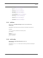
Litho.h Functions
Background
316.7 Litho.h Functions
For details on these commands, refer to the following sections:
38
•
LithoAbort: Section 316.7.1 on Page 39
•
LITHO_BEGIN: Section 316.7.2 on Page 39
•
LITHO_END: Section 316.7.3 on Page 39
•
LithoDisplayStatusBox: Section 316.7.4 on Page 39
•
LithoRemoveStatusBox: Section 316.7.5 on Page 39
•
LithoFeedback: Section 316.7.6 on Page 40
•
LithoSignal: Section 316.7.7 on Page 40
•
LithoGet: Section 316.7.8 on Page 41
•
LithoGetSoft: Section 316.7.9 on Page 41
•
LithoMoveZ: Section 316.7.10 on Page 41
•
LithoPause: Section 316.7.11 on Page 42
•
LithoPulse: Section 316.7.12 on Page 42
•
LithoRamp: Section 316.7.13 on Page 43
•
LithoRelease: Section 316.7.14 on Page 43
•
LithoSet: Section 316.7.15 on Page 43
•
LithoSetSoft: Section 316.7.16 on Page 44
•
LithoTranslate: Section 316.7.17 on Page 44
•
LithoTrigger: Section 316.7.18 on Page 44
•
LithoWaitFor: Section 316.7.19 on Page 45
•
Gui.h Functions: Section 316.8 on Page 46
NanoLithography
Rev. A
Litho.h Functions
LithoAbort
316.7.1
LithoAbort
PROTOTYPE: void LithoAbort();
DESCRIPTION: LithoAbort is used inside a lithography block to jump to the LITHO_END command.
RETURN VALUE: None
316.7.2
LITHO_BEGIN
PROTOTYPE: LITHO_BEGIN
DESCRIPTION: LITHO_BEGIN prepares the SPM for lithography
Note: To stop the scanning, use LithoScan(false). To move the tip to the center of the scan
area, use LithoCenterXY().
316.7.3
LITHO_END
PROTOTYPE: LITHO_END
DESCRIPTION: This macro is placed at the end of a set of lithography commands. Execution of this
command causes the SPM to resume normal scanning.
316.7.4
LithoDisplayStatusBox
PROTOTYPES: void LithoDisplayStatusBox();
DESCRIPTION: Displays the lithography status box.
316.7.5
LithoRemoveStatusBox
PROTOTYPES: void LithoRemoveStatusBox();
DESCRIPTION: Removes the lithography status box.
Rev. A
NanoLithography
39
Litho.h Functions
LithoFeedback
316.7.6
LithoFeedback
PROTOTYPES: bool LithoFeedback(bool on);
DESCRIPTION: LithoFeedback turns Z feedback on or off.
RETURN VALUE: FALSE if the command fails.
EXAMPLE:
LithoFeedback (false);//turn off feedback
316.7.7
LithoSignal
The LithoSignal type is an argument, or boolean command, for several lithography commands:
LithoSet, LithoSetSoft, LithoGet, LithoGetSoft, LithoRamp and LithoPulse (see descriptions
below). LithoSignal values may be set to any of the following analog lines:
Table 316.7a LithoSignal Analog Lines
Input channels
Output channels
Channel
40
Hard Units
Soft Units
lsX
V
lsY
V
lsZ
V
nm
lsZlimit
V
nm
lsBias
mV
lsSetpoint
V (AFM), nA (STM)
lsAna1
V
lsAna2
V
lsAna2HV
V
lsAna3
V
lsAna4
V
IsIn0
V
lsAuxA
V
lsAuxB
V
lsAuxC
V
lsAuxD
V
lsIn1
V
lsIn2
V
lsIn3
V
lsIn4
V
NanoLithography
nm
Rev. A
Litho.h Functions
LithoGet
Applications on Specific Analog Lines
Specific applications or microscope modes may only be used with the following analog lines:
316.7.8
•
lsBias is available on STM microscopes only.
•
lsAna1 is available on non-EC microscopes in STM, and contact AFM microscopes only.
•
lsAna2 and lsAna2HV are available on AFM microscopes where input attentuation is
disabled and on all STM microscopes.
•
lsAna3 and lsAna4 are available only NanoScope IIIa controllers which have been upgraded
with additional D/A converters.
LithoGet
PROTOTYPES: double LithoGet (LithoSignal i);
DESCRIPTION: Returns the current value of the specified channel in its hard units, (typically the
signal’s hardware representation). such as volts.
316.7.9
LithoGetSoft
PROTOTYPES: double LithoGet (LithoSignal i);
DESCRIPTION: Returns the current value of the specified channel in its soft units, (typically the signal’s
software representation), such as nanometers.
316.7.10 LithoMoveZ
PROTOTYPES: bool LithoMoveZ(double dz, double rate);
DESCRIPTION: LithoMoveZ moves the tip along the Z-axis (dz) at a specified rate. Units for dz are
micrometers; units for rate are in micrometers per second (µm/sec). Positive values for dz moves the tip
away from the sample. This command turns off feedback.
RETURN VALUE: FALSE if the command fails.
EXAMPLE:
LithoMoveZ(-0.020, 0.040);//move the tip 20 nm toward the sample at 40 nm/s.
See also, Optimizing the LithoMoveZ Command below.
Rev. A
NanoLithography
41
Litho.h Functions
LithoPause
Optimizing the LithoMoveZ Command
To use LithoMoveZ and translation for doing lithography, complete the following:
1. Disable the Slow scan axis, then select Scope mode to examine the surface slope.
Note: This reveal the sample tilt along the X-axis.
2. Adjust the sample until this axis is level. (Several withdrawals and engages may be required to
get the adjustments right.).
3. Set the Scan angle to 90° so that the Scope mode trace reveals the sample along its Y-axis;
adjust the sample again until level. Return the Scan angle setting to 0° to verify the sample is
still level in its X-axis. You are now ready to do your lithography.
4. Verify that the sample is level in both axes.
5. Capture the plane of the image using the Capture Plane command.
If the depth of your etched lines tend to slope from one end of the line to the other, this may indicate
that the sample is not sufficiently level, or that you need to obtain an improved Capture Plane.
Accurate planefit captures require good scans and flat samples. Try to use a smooth area of the sample
for planefits and lithography.
316.7.11 LithoPause
PROTOTYPES: bool LithoPause(double secs);
DESCRIPTION: LithoPause halts lithography for the specified number of seconds (secs).
RETURN VALUE: FALSE if the command fails.
EXAMPLE: LithoPause(0.5);//pause for 0.5 seconds.
316.7.12 LithoPulse
PROTOTYPES: bool LithoPulse(LithoSignal o, double v, double secs);
DESCRIPTION: LithoPulse pulses the output to v (volts) for secs (seconds). The output then returns
to its setting before pulsing.
RETURN VALUE: FALSE if the command fails.
EXAMPLE:
//pulse the Bias voltage to 2 volts for a period of 0.1 seconds.
LithoPulse(lsBias, 2, 0.1);
42
NanoLithography
Rev. A
Litho.h Functions
LithoRamp
316.7.13 LithoRamp
PROTOTYPES: bool LithoRamp(LithoSignal o, double start, double end, double secs);
DESCRIPTION: Ramps the output specified in o from the voltage specified in start to the voltage
specified in end over the specified time defined in secs. The output then returns to its previous voltage
and output settings.
RETURN VALUE: FALSE if the command fails.
EXAMPLE:
//ramp the Bias voltage from -2 to 2 volts over a period of 5 seconds.
LithoRamp(lsBias, -2, 2, 5);
316.7.14 LithoRelease
PROTOTYPES: bool LithoRelease(bool allow);
DESCRIPTION: Allows the user turn on and off user interface processing during lithography commands.
This makes lithography run faster for critical timing applications but locks out all user access.
RETURN VALUE: FALSE if the command fails.
EXAMPLE:
//Produce a 50 ms pulse on A1. Without the LithoRelease command,
//the pulse may be significantly longer than 50 ms.
LithoRelease (false);//turn off user interface processing
LithSet(lsAna1, 10);
LithoPause(0.050);
LithoSet(lsAna1, 0);
LithoRelease (true);//turn on user interface processing
316.7.15 LithoSet
PROTOTYPES: bool LithoSet(LithoSignal o, double v);
DESCRIPTION: LithoSet sets the specified signal o to v in hard units, (typically the signal’s hardware
representation) such as volts.
RETURN VALUE: FALSE if the command fails.
EXAMPLE:
LithoSet (lsAna2, -5)//sets analog line #2 to -5 volts.
Rev. A
NanoLithography
43
Litho.h Functions
LithoSetSoft
316.7.16 LithoSetSoft
PROTOTYPES: bool LithoSetSoft(LithoSignal o, double v);
DESCRIPTION: LithoSetSoft sets the specified signal o to v in soft units, (typically the signal’s
software representation) such as nanometers.
RETURN VALUE: FALSE if the command fails.
316.7.17 LithoTranslate
PROTOTYPES: bool LithoTranslate(double dx, double dy, double rate);
DESCRIPTION: LithoTranslate moves the tip along the X-axis (dx) and Y-axis (dy) at a specified
rate. Units for dx and dy are microns; units for rate are in microns per second (um/sec). If feedback is
off, the tip will also be moved in Z according to the captured planefit in an attempt to keep the sampleto-tip distance constant.
RETURN VALUE: FALSE if the command fails.
EXAMPLE: LithoTranslate (5,0,2);//Translate the tip 5 µm along the X-axis at 2 µm/s.
316.7.18 LithoTrigger
PROTOTYPE: bool LithoTrigger(TriggerLine line);
DESCRIPTION: LithoTrigger sends out approximately 200 ns pulse (hi/lo/hi) on the specified digital
line.
RETURN VALUE: FALSE if the command fails.
EXAMPLE: LithoTrigger (tlD0);//send pulse out digital line D0:
TRIGGERLINE VALUES: The TriggerLine type is used as an argument for the LithoTrigger
command (see description below). TriggerLine values may be assigned to any of the following analog
lines.
Table 316.7a TriggerLine Analog Lines
44
Line
Value
tlD0
-1
tlD1
-2
tlDR0
0x0001
tlDR1
0x0002
tlDR2
0x0004
tlDR3
0x0008
NanoLithography
Rev. A
Litho.h Functions
LithoWaitFor
Line
Value
tlDR4
0x0010
tlDR5
0x0020
tlDR6
0x0040
tlDR7
0x0080
tlDR8
0x0100
tlDR9
0x0200
tlDR10
0x0400
tlDR11
0x0800
tlLine
0x4000
tlFrame
0x8000
Applications on Specific Analog Lines
Specific applications or microscope modes may only be used with the following analog lines:
•
tlD0 and tlD1 lines are only available on non-EC, Small Sample AFM and STM microscopes.
•
tlDR0—tlDR11, tlLine and tlFrame are only available on SPMs with NanoScope IIIa
controllers.
316.7.19 LithoWaitFor
PROTOTYPE: bool LithoWaitFor(LithoSignal i, double v);
DESCRIPTION: LithoWaitFor causes the lithography program to pause until the specified input drops
below 'v'.
RETURN VALUE: FALSE if the command fails.
EXAMPLE: LithoWaitFor (lsIn1B, 0);//wait for input 1B to drop below 0 volts.
Rev. A
NanoLithography
45
Gui.h Functions
LithoWaitFor
316.8 Gui.h Functions
The functions in the gui.h file header allow the user to create and manage the display of standard and
custom menus and dialog boxes.
Refer to the following sample list of gui.h function prototyes:
46
•
AddButton: Section 316.8.1 on Page 47
•
AddCheckBox: Section 316.8.2 on Page 47
•
AddFloatControl: Section 316.8.3 on Page 48
•
AddIntControl: Section 316.8.4 on Page 48
•
AddMenuItem: Section 316.8.5 on Page 48
•
AddRadioButton: Section 316.8.6 on Page 48
•
AddRadioGroup: Section 316.8.7 on Page 49
•
AddStringEntry: Section 316.8.8 on Page 49
•
Askxxxx: The Ask Group: Section 316.8.9 on Page 49
•
AtMenuBuild: Section 316.8.10 on Page 50
•
ClearMenuBar: Section 316.8.11 on Page 50
•
CustomMenuBar: Section 316.8.12 on Page 50
•
Debug: Section 316.8.13 on Page 50
•
DelMenuItem: Section 316.8.14 on Page 50
•
EraseMessage: Section 316.8.15 on Page 51
•
FindMenuItem: Section 316.8.16 on Page 51
•
IsMessageBoxUp: Section 316.8.17 on Page 51
•
LockGUI: Section 316.8.18 on Page 51
•
LockMenu: Section 316.8.19 on Page 51
•
ModalDialog: Section 316.8.20 on Page 52
•
NormalMenuBar: Section 316.8.21 on Page 52
•
PasswordQuery: Section 316.8.22 on Page 52
•
RemoveSayBox: Section 316.8.23 on Page 52
NanoLithography
Rev. A
Gui.h Functions
AddButton
316.8.1
•
RunDialog: Section 316.8.24 on Page 53
•
SayError: Section 316.8.25 on Page 53
•
SayMessage: Section 316.8.26 on Page 53
•
SayWarning: Section 316.8.27 on Page 53
•
SelectRadioButton: Section 316.8.28 on Page 53
•
ShowMessage: Section 316.8.29 on Page 54
•
UnlockGUI: Section 316.8.30 on Page 54
•
UnlockMenu: Section 316.8.31 on Page 54
AddButton
PROTOTYPES: void AddButton(DialogBox db, char *text, int id, PFV action,
UIBFlags flags);
DESCRIPTION: Adds a button with the specified text to the dialog box specified by
ab.
EXAMPLE:
UIBFlags can be any combination of the following values:
enum UIBFlags
{
uibNone= 0,
uibDefault= 0x00000100,
uibClose= 0x00000200
};
316.8.2
AddCheckBox
PROTOTYPE: void AddCheckBox(DialogBox db, char *text,
bool & checked);
DESCRIPTION: AddCheckBox adds a check box with the specified text to the dialog box
specified by db.
Rev. A
NanoLithography
47
Gui.h Functions
AddFloatControl
316.8.3
AddFloatControl
PROTOTYPE: void AddFloatControl(DialogBox db, char *label, int & value, int min,
int max);
DESCRIPTION: AddFloatControl adds a control which allows the entry of a floating point number to
the dialog box designated by db. The specified label will be displayed next to the entry field. The
entered value is returned in value. The minimum and maximum values allowed are specified in min
and max, respectively.
316.8.4
AddIntControl
PROTOTYPE: void AddIntControl(DialogBox db, char *label, int & value, int min, int max);
DESCRIPTION: AddIntControl adds a control which allows the entry of an integer to the dialog box
designated by db. The specified label will be displayed next to the entry field. The entered value is
returned in value. The minimum and maximum values allowed are specified in min and max,
respectively.
316.8.5
AddMenuItem
PROTOTYPE: MenuItem AddMenuItem(MenuItem parent, char *name, PFV fn);
DESCRIPTION: AddMenuItem adds a menu item with the name specified by name to the menu
specified by parent. To add an item to the menu bar, specify menuBar as the parent. The function fn is
called when the item is selected by the user. If fn is NULL, no function is called.
When an ampersand (&) is placed in the character string, the character immediately following the
ampersand becomes a “quick-key” for that menu item in the dialog box. (For example, “M” is the
quick-key when &Microscope is specified in the text string.)
RETURN VALUE: A handle to the newly created menu item is returned. This handle may be used as
the parent argument in subsequent calls to AddMenu to create submenus. See also, FindMenuItem,
DelMenuItem.
316.8.6
AddRadioButton
PROTOTYPE: void AddRadioButton(RadioGroup rg, char *label, ResID id);
DESCRIPTION: AddRadioButton adds a radio button to a group of radio buttons specified by rg.
The new radio button receives the name specified by label. See also, AddRadioGroup,
SelectRadioGroup.
48
NanoLithography
Rev. A
Gui.h Functions
AddRadioGroup
316.8.7
AddRadioGroup
PROTOTYPE: RadioGroup AddRadioGroup(DialogBox db, char *title, ResID & selected);
DESCRIPTION: AddRadioGroup adds a radio group to dialog box db, to which radio buttons can then be
added. The radio group receives the name specified by title.
RETURN VALUE: A handle to the newly created radio group is returned. This handle may be used as the
parent argument in subsequent calls to AddRadioButton. See also, AddRadioButton,
SelectRadioGroup.
316.8.8
AddStringEntry
PROTOTYPE: void AddStringEntry(DialogBox db, char *prompt, int width, char *buffer, int
buflen);
DESCRIPTION: AddStringEntry adds a string entry field to the dialog box db. The string specified by
prompt will e displayed adjacent to the entry field. The entered text is stored in buffer.
316.8.9
Askxxxx: The Ask Group
PROTOTYPE:
void AskCancel(char *title, char *fmt, ...);
bool AskCancelOk(char *title, char *fmt, ...);
bool AskNoYes(char *title, char *fmt, ...);
void AskOk(char *title, char *fmt, ...);
bool AskOkCancel(char *title, char *fmt, ...);
void AskQuit(char *title, char *fmt, ...);
bool AskYesNo(char *title, char *fmt, ...);
DESCRIPTION: Each of these functions display a modal dialog box. The title of the dialog box is
specified by title. Any messages displayed in the modal dialog box are specified by fmt and
remaining parameters (printf style). In addition the box will have buttons corresponding to the name
of the function called. For instance AskYesNo will have a ‘yes’ and a ‘no’ button. The box is closed
when any button is selected.
RETURN VALUE: TRUE if selecting the OK or YES button; FALSE if box closes by selecting the exit
option (i.e., “X”).
Rev. A
NanoLithography
49
Gui.h Functions
AtMenuBuild
316.8.10 AtMenuBuild
PROTOTYPE: void AtMenuBuild(void (*fn)(int));
DESCRIPTION: The AtMenuBuild function registers the function fn such that when a menu bar is
being built, the registered function (fn) is called. This allows adding custom menu items using
NanoScript. See also, AddMenuItem, FindMenuItem, DelMenuItem, ClearMenuBar,
CustomMenuBar.
316.8.11 ClearMenuBar
PROTOTYPE: void ClearMenuBar();
DESCRIPTION: The ClearMenuBar function clears all items from the current menu bar. See also,
FindMenuItem, DelMenuItem, AddMenuItem.
316.8.12 CustomMenuBar
PROTOTYPE: void CustomMenuBar();
DESCRIPTION: The function CustomMenuBar displays a user configured menu bar. This menu bar is
not used by any other portion of the NanoScope system. See also, NormalMenuBar, AddMenuItem,
FindMenuItem, DelMenuItem, ClearMenuBar.
316.8.13 Debug
PROTOTYPE: int Debug(char *fmt, ...);
DESCRIPTION: The function Debug outputs a string as specified to the system debug box. The
arguments are printf style. This box can also display by selecting Ctrl-Alt-D.
RETURN VALUE: Returns the number of characters output to the debug box.
316.8.14 DelMenuItem
PROTOTYPE: void DelMenuItem(MenuItem item);
DESCRIPTION: The function DelMenuItem removes the specified menu item.
50
NanoLithography
Rev. A
Gui.h Functions
EraseMessage
316.8.15 EraseMessage
PROTOTYPE: void EraseMessage();
DESCRIPTION: The EraseMessage function erases the message box that has been displayed by the
ShowMessage function. See also, ShowMessage, SayError, SayWarning, SayMessage,
RemoveSayBox.
316.8.16 FindMenuItem
PROTOTYPE:MenuItem FindMenuItem(MenuItem parent, char *name);
DESCRIPTION: The FindMenuItem function locates a menu item with the string specified by name
in the menu referred to by parent. To find an item in the main menu bar, specify menuBar as the
parent.
RETURN VALUE: Returns the handle to the found menu item. If no matching item is found, NULL is
returned. See also, AddMenuItem, DelMenuItem.
316.8.17 IsMessageBoxUp
PROTOTYPE:bool IsMessageBoxUp();
DESCRIPTION: The function IsMessageBoxUp queries for the presence of the user interface message
box.
RETURN VALUE: TRUE if yes, otherwise FALSE.
316.8.18 LockGUI
PROTOTYPE: void LockGUI();
DESCRIPTION: The function LockGUI locks the user interface preventing all user interaction with the
system until the UnlockGUI function is called. See also, UnlockGUI.
316.8.19 LockMenu
PROTOTYPE: void LockMenu();
DESCRIPTION: The function LockMenu locks the current menu bar in place preventing it from being
replaced with another menu bar when the software changes modes. This is useful when the macro has put
up a custom menu bar. See also, UnlockMenu, CustomMenuBar.
Rev. A
NanoLithography
51
Gui.h Functions
ModalDialog
316.8.20 ModalDialog
PROTOTYPE:DialogBox ModalDialog(char *title);
DESCRIPTION: The function ModalDialog creates a dialog box with name as specified in title.
EXAMPLE:
The example program below creates a dialog box with a title of “Title String.” The box has one entry
field labelled “Size,” which allows float entries from zero to 200. The value entered by the user is
stored in size. Additionally, there are two buttons in the dialog box; one is labelled “Ok” and the
other “Cancel.”
{
float size = 30;
DialogBox dlg = ModalDialog (“Title String”);
AddFloatControl (dlg, “Size”, size, 0, 200);
AddButton (dlg, “&Ok”, 1 NULL,
uibClose|uibDefault);
AddButton (dlg, “&Cancel”, 0, NULL, uibClose);
if (RunDialog(dlg) == 0)
return;
}
RETURN VALUE: Returns the handle of the newly created dialog box.
316.8.21 NormalMenuBar
PROTOTYPE: void NormalMenuBar();
DESCRIPTION: The function NormalMenuBar displays the default NanoScope menu bar.
See also, CustomMenuBar.
316.8.22 PasswordQuery
PROTOTYPE: bool PasswordQuery();
DESCRIPTION: The function PasswordQuery prompts the user to enter a password.
RETURN VALUE: TRUE if a valid password is entered; otherwise FALSE
316.8.23 RemoveSayBox
PROTOTYPE: void RemoveSayBox();
DESCRIPTION: The function RemoveSayBox removes any message box from the screen that was
invoked by a Sayxxxx function. See also, SayError, SayWarning, SayMessage.
52
NanoLithography
Rev. A
Gui.h Functions
RunDialog
316.8.24 RunDialog
PROTOTYPE: int RunDialog(DialogBox db);
DESCRIPTION: The function RunDialog displays the dialog box specified by
parameter db. The function returns when the box is closed by the user.
RETURN VALUE: Returns the id of the button used to close the box. See also, ModalDialog.
316.8.25 SayError
PROTOTYPE: void SayError(char *fmt, ...);
DESCRIPTION: The function SayError displays a message box with the title of “Error”. The
parameters specify the message to be displayed and are in printf style. See also, RemoveSayBox.
316.8.26 SayMessage
PROTOTYPE: void SayMessage(char *title, char *fmt, ...);
DESCRIPTION: The function SayMessage displays a message box with the specified title value.
The remaining parameters specify the message to be displayed and are in printf style. See also,
RemoveSayBox.
316.8.27 SayWarning
PROTOTYPE: void SayWarning(char *fmt, ...);
DESCRIPTION: The function SayWarning displays a message box with the title of “Warning”.
The parameters specify the message to be displayed and are in printf style.
See also, RemoveSayBox.
316.8.28 SelectRadioButton
PROTOTYPE: void SelectRadioButton(RadioGroup rg, ResID id);
DESCRIPTION: The function SelectRadioButton selects the radio button specified by the id in
the radio group rg. See also, RunDialog.
Rev. A
NanoLithography
53
Gui.h Functions
ShowMessage
316.8.29 ShowMessage
PROTOTYPE: void ShowMessage(char *title, char *fmt, ...);
DESCRIPTION: The function ShowMessage invokes a message box with the title as specified by
title. The remaining parameters specify the message to be displayed in printf style. While this
box is up the user is prevented from interacting with the system. It must be removed using a call to
EraseMessage. See also, EraseMessage.
316.8.30 UnlockGUI
PROTOTYPE: void UnlockGUI();
DESCRIPTION: The function UnlockGUI removes the lock placed by the LockGUI function
preventing all user interaction with the system. See also, LockGUI.
316.8.31 UnlockMenu
PROTOTYPE: void UnlockMenu();
DESCRIPTION: The function UnlockMenu removes the lock placed by the LockMenu function
preventing the menu bar from changing. See also, LockMenu.
54
NanoLithography
Rev. A