1
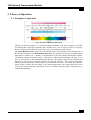
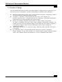
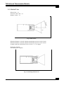
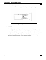
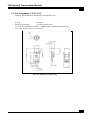
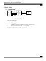
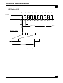
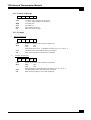
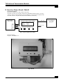
TN9 Infrared Thermometer Module
User Manual
TN9 Infrared Thermometer Module
Contents
1 GENERAL DESCRIPTION ....................................................................................3
EDITION JULY 2004......................................................................................................3
2 THEORY OF OPERATION....................................................................................4
2.1 PRINCIPLES OF OPERATION .....................................................................................4
2.2 FEATURES OF DESIGN .............................................................................................5
2.3 FIELD OF VIEW .......................................................................................................6
2.4 EMISSIVITY ............................................................................................................7
3 SPECIFICATION ....................................................................................................8
3.1 ABSOLUTE MAXIMUM RATING ...............................................................................8
3.2 DC CHARACTERISTICS ...........................................................................................8
3.3 MEASUREMENT SPECIFICATION ..............................................................................9
3.4 PIN ASSIGNMENT OF TN0; TN9............................................................................ 10
4 SERIAL OUTPUT.................................................................................................. 11
4.1 TYPICAL DIAGRAM ............................................................................................... 11
4.2 TIMING OF SPI ..................................................................................................... 12
4.2.1 Format of Message........................................................................................ 13
4.2.2 Example ........................................................................................................ 13
4.2.3 How to modify Emissivity? (How to write Emissivity into EEPROM)............. 14
5 INTERFACE DEMO BOARD: HUB-D................................................................ 15
6 INTERFACE PROGRAM FOR PC...................................................................... 16
TN9 Infrared Thermometer Module
1 General Description
This document describes the user guide of TNm Series (TN0; TN9).
Edition July 2004
Copyright:
All right reserved. Reproduction in any manner, in whole or in part is straightly prohibited without written
permission. This information contained in this document is subject to change without
notice.
Limited Warranty:
This data sheet contains information specific to products manufactured at the time of its publication,
Contents herein do not constitute a warranty.
Trademark Acknowledgements:
All trademarks are the property of their respective owners.
TN9 Infrared Thermometer Module
2 Theory of Operation
2.1 Principles of Operation
Fig 1. the Infrared Radiation Spectreum
Infrared, just like any light ray, is an Electromagnetic Radiation, with lower frequency (or longer
wavelength) than visual light. Anything above absolute zero (-273.15 degrees Celsius or 0 degrees
Kelvin), radiates in the infrared. Even ice cube, snow, your refrigerator emit infrared.
The Stefan-Boltzmann Law, where the total radiation energy is proportional to the fourth power of
the absolute temperature and Wien Displacement Law, the product of the peak wavelength and the
temperature is found to be a constant, are implemented in the TNm infrared thermometer module.
The infrared radiation of measure target is collected by a infrared mirror through a IR filter of 5 or
8um cut in frequency to the infrared thermopile detector. The detector signal will be amplified and
digitalize by the low noise and high linearity OP and AD convertor. The ambient temperature
sensor( usually included in the same package as the thermopile detector ) is set in the space near the
optical system to detect the fast change of the ambient temperature. The signal processing section
receives the signals from these temperature sensors to calculate the target surface temperature by a
mathematical algorithm.
TN9 Infrared Thermometer Module
2.2 Features of Design
The TNm infrared thermometer module is specially designed for a high sensitivity, high accuracy, low
noise and low power consumption. A number of design features contribute to the performance:
l
l
l
l
l
MEMS thermopile detector and a high accurate ambient temperature compensation technics
care used for the TNm infrared thermometer module.
developed a proprietary Infrared-System-On-Chip device that integrates all
hardware items onto one IC. Using this innovative SoC technology, TNm infrared thermometer
module has become a highly affordable and compact product.
products can faithfully withstand a thermal shock of 10degC/18degF. Our products
are adept in maintaining accuracies under widely changing environmental conditions. For
example, the errors from environmental changes of older IRTs can reach 1.6degC, requiring up
to 30 minutes to stabilize, while TNm error differential is only 0.7degC, needing only
7 minutes to restabilize.
TNm products operate from a 3 Volt power supply, while many other older IRTs still require a
9 Volt supply.
has maintained a NIST or National Measurement Laboratory traceable Temperature
Primary Standard. All the TNm products are calibrated under traceable infrared standard
sources. The calibration data and serial number are saved in a EEPROM on the module.
TN9 Infrared Thermometer Module
2.3 Field of View
What is D:S = 1:1
This device has a D:S = 1:1
Distance : Spot = 1:1
Fig 2. Field of View
When the Distance is 10 inch, then the measurement spot size is also 10 inch.
When the Distance is 20 inch, then the measurement spot size is also 20 inch.
In other words, the FOV(Field of View) is 26.6 x 2 = 53.2 degree
Beware the Vignette
Good Design, No Vignette
Fig 3. Good Design Field of View
TN9 Infrared Thermometer Module
Bad Design Vignette
The Sensor “see” the edge of the housing
So the measurement in fact is the averaging of the real target and the edge of housing.
Fig 4. Bad Design Field of View
2.4 Emissivity
Understanding an object's emissivity, or its characteristic "radiance" is a critical component in the
proper handling of infrared measurements. Concisely, emissivity is the ratio of radiation emitted by a
surface or blackbody and its theoretical radiation predicted from Planck's law. A material's surface
emissivity is measured by the amount of energy emitted when the surface is directly observed. There
are many variables that affect a specific object's emissivity, such as the wavelength of interest, field of
view, the geometric shape of the blackbody, and temperature. However, for the purposes and
applications of the infrared thermometer user, a comprehensive table showing the emissivity at
corresponding temperatures of various surfaces and objects is displayed.
TN9 Infrared Thermometer Module
3 Specification
3.1 Absolute Maximum Rating
Characteristics
Symbol
Ratings
DC Supply Voltage
V+
Input Voltage Range
VIN
<7.0V
-0.5V to V+ + 0.5V
Note: Stresses beyond those given in the Absolute Maximum Rating table may cause
operational errors or damage to the device. For normal operational conditions see AC/DC
Electrical Characteristics.
3.2 DC Characteristics
(VDD = 3.0V, TA = 25℃)
Limit
Characteristics
Symbol
Unit
Min
Typ.
Max
Test condition
Operating Voltage
VDD
2.5
-
3.6
V
Operating Current
IOP
-
4
6
mA
Standby Current
Input High Level
Input Low Level
Output High I
Output Sink I
ISTBY
VIH
VIL
IOH
IOL
2.0
-
2
-2.0
2.5
3
0.8
-
µA
V
V
mA
mA
VDD = 3.0V,
FCPU = 600KHz
VDD = 3.0V
VDD = 3.0V
VDD = 3.0V
VDD = 3.0V, VOH = 2.4V
VDD = 3.0V, VOH = 0.8V
Unit
Test condition
(VDD = 4.5V, TA = 25℃)
Characteristics
Limit
Symbol
Min
Typ.
Max
Operating Voltage
VDD
3.6
-
5.0
V
Operating Current
IOP
-
6
9
mA
Standby Current
Input High Level
Input Low Level
Output High I
Output Sink I
ISTBY
VIH
VIL
IOH
IOL
3.0
-
3
-2.0
2.5
4.5
0.8
-
µA
µA
µA
mA
mA
VDD = 4.5V,
FCPU = 600KHz
VDD = 4.5V
VDD = 4.5V
VDD = 4.5V
VDD = 4.5V, VOH = 3.5V
VDD = 4.5V, VOL = 0.8V
TN9 Infrared Thermometer Module
3.3 Measurement Specification
Measurement Range
-33~220°C / -27~428°F
Operating Range
-10~50°C / 14~122°F
Accuracy Tobj=15~35°C, Tamb=25°C
+/-0.6°C
Full Range Accuracy #AC
+/-2%, 2°C
Resolution at -9.9~199.9°C
1/16°C=0.0625 (fall range)
Response Time (90%)
1sec
D:S
1:1
Emissivity
0.01~1 step.01
Update Frequency
1.4Hz
Dimension
12x13.7x35mm
Wave Length
5um-14um
Weight (no battery)
9g
Power Supply
3V or 5V
TN9 Infrared Thermometer Module
3.4 Pin Assignment of TN0; TN9
Warning: The Dimension in this drawing is for reference only.
V: Vdd
G: GND
D: Data (Serial Data)
C: Clock (Serial Clock)
A: Action Pin ( pull low to measure, floating while to Write Data into the IRT)
Note: TN0; TN9 has the same pin assignment.
Fig 5. the Module External Drawing
TN9 Infrared Thermometer Module
4 Serial Output
4.1 Typical Diagram
TN1
V
D
C
G
A
+3V
TTL
Interface
(MCU)
Clock +Data+GND
PC
RS-232 or other
Fig 6. Typical Diagram
DUT to TTL Interface (MCU)
V:Vcc
D:Data
C:Clock (2KHz)
G:GND
A:ActionKey (When Pull Low, the device will measure Tbb continuousely.)
DUT is Output the data, while MCU is receving the Data
Note: Data Pin is High when there is no data , Time Out > 2ms
TN9 Infrared Thermometer Module
4.2 Timing of SPI
0
1
2
3
4
5
6
7
b6
b5
b4
b3
b2
b1
b0
0
1
CLOCK
DATA
b7
b7
b6
500us
Byte 0
Message format
Item MSB
DATA
LSB
Sum
CR
DATA
20ms
> 0.1 sec
Fig 7. Timing of SPI
Byte 1
TN9 Infrared Thermometer Module
4.2.1 Format of Message
Item MSB LSB Sum CR
Item
“L”(4CH): Tobj (Temperature of Object)
“f” (66H): Tamb (Ambient Temperature)
8 bit Data Msb
8 bit Data Lsb
Item+MSB+LSB=SUM
0DH, End of the message
MSB
LSB
Sum
CR
4.2.2 Example
1.
Object Tempurature
4C
14
Item
Data
8A
0D
4CHà “L” the item code of Object tempurature
MSB
14H
LSB
2AH
Real Tempurature Value [Hex2Dec(142AH)]/16-273.15= 49.475 ℃
CheckSum 4CH+14H+2AH=8AH (Only Low Byte)
0DH à’Carriage Return’ means End of Message
Sum
CR
2.
2A
Ambiant Tempurature
66
Item
Data
Sum
CR
12
C3
3B
0D
66Hà “f” the item code of Ambient tempurature
MSB
12H
LSB
C3H
Real Tempurature Value [Hex2Dec(12C3H)]/16-273.15= 27.03 ℃
CheckSum 66H+12H+C3H=3BH (Only Low Byte)
0DH à’Carriage Return’ meas End of Message
TN9 Infrared Thermometer Module
4.2.3 How to modify Emissivity? (How to write Emissivity into EEPROM)
Warning: misuse may result in EEPROM other data modified, this may destroy the calibration. the
device may become useless!
1) This Infrared Thermometer module is calibrated for Emissivity=0.95 defaultly. Most of
Non-metal material have emissivity near to 0.95. But the infrared emissivity of normal metal is
much lower and may have to modify the setting of the module for certain application.
2) The communication format and how to read data from DUT's CommuMode:
ItemCode + HighByte + LowByte + CheckSum(ItemCode+HighByte+LowByte) + CR , total
40 clocks(& data).
3) For write Emissivity to DUT, the communication format is the same as read.
=> “S”+ HighByte(Emissivity value) + 04H + CheckSum(ItemCode + HighByte + 04H) + CR
Emissivity value = HighByte(hex)/100(dec),
For example: HighByte = 5F(hex)=95(dec) -> emissivity = 95(dec)/100(dec) = 0.95.
keep the LowByte data = 04(hex).
4) The trick for write data to DUT is as below
a. Action pin need to be floating when we want to write data to DUT.
b. As you know, DUT will do routine data out by 40 clocks & datas with communication
format.
After the 40th clock, DUT will pull the CLK & DATA pin to weak high for waiting if
there is External CPU want write data to DUT.
Please let External CPU start send 1st clock within the timing T1 after the 40th clock.
: 5ms < T1 < 10ms
c. The frequency of CLK should be 2KHz.
d. DUT will latch the data at negative edge of CLK, so data should be ready before the
negative edge of 1st writing clock.
5) For example,
Emissivity = 0.95
Emissivity = 0.80
==> “S” + 5F(hex) + 04(hex) + B0(hex) + CR
==> “S” + 50(hex) + 04(hex) + A7(hex) + CR
6) Finally, how do we know write emmissivity success.
About 5 ms after you send CLK & DATA to DUT completely.
DUT should have 3 kinds of response.
a. DUT will send out the same data whcih External CPU had write to DUT.
(We call this ECHO). That means write emmissivity success.
b. DUT will send out “S” + FF(hex) + FF(hex) + CheckSum( “S” + FF + FF ) + CR.
That means DUT find data checksum error = a wrong data receiving.
DUT will forget the data, and you need to re-write again.
c. DUT have no response as above
That means DUT don't get full 40 clocks.
Please check the clock & data which control by External CPU.
Especially, please make sure the T1 timing is right.
TN9 Infrared Thermometer Module
5 Interface Demo Board: Hub-D
General Description:
Hub-D is an Interface box with LCD, for TN series.
This Box can work as an interface between the IRTm(IRT Module) and PC. see Fig.A
“Hub_D” has a 2-column character type LCD Display, it can also work without the PC.
The Hub will show Tobj & Tamb (data from the IRTm) continuously.
IRT module
(TN0; TN9)
Vcc
Data
Clock
GND
Action
RS-232
Interface Demo Board (Hub)
Tobj=
Tamb=
99.6C
19.8C
Power +5V
Power
Hub Reset
IRTm Reset
Action
Fig 8. Typical Application of Hub
Model No:Hub-D
Program: TNmDB001.exe
Fig 9. Hub-D
PC running a
program
TN9 Infrared Thermometer Module
6 Interface Program for PC
Program: TNmDB001.exe
a Free version for demostration can be download
l
l
l
l
Running under a DOS window (in MS Windows environment)
This program will show:
Tbb (Tobj) ; Tamb
in degC;degF continuously
Status of IRT
Modification of the Emissivity
degC/degF unit change