1
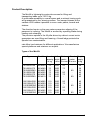
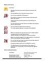
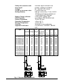
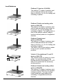
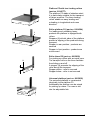
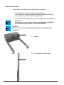
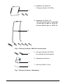
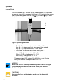
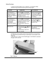
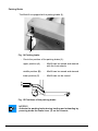
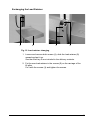
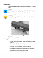
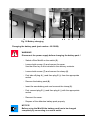
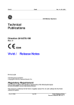
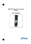
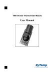
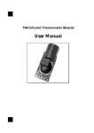
Minilift 70/110 Operating Instructions Edition 11/04 Contents Product Description .................................................................................................... 3 Safety Instructions ...................................................................................................... 4 Technical Specification ................................................................................................ 4 Load Retainers ............................................................................................................ 6 Delivery Contents ........................................................................................................ 8 Mounting the Minilift .................................................................................................. 10 Mounting the Lift Pillar ......................................................................................... 10 Mounting the Handlebar on the Minilift 70 ............................................................................................................. 12 Mounting the Handlebar on the Minilift 110 ........................................................................................................... 13 Mounting the Load Retainer ................................................................................ 14 Start-Up ..................................................................................................................... 15 Checking and Adjusting the Strut Sensor .............................................................................................................. 16 Operation .................................................................................................................. 18 Control Panel ...................................................................................................... 18 Safety Shutdown ................................................................................................. 19 Parking Brake ...................................................................................................... 20 Exchanging the Load Retainer ................................................................................. 21 Maintenance ............................................................................................................. 22 Charging the Battery Pack .................................................................................. 22 Changing the Battery Pack ................................................................................. 23 EC Conformity Declaration ....................................................................................... 24 2 Product Description The Minilift in lightweight construction serves for lifting and transporting loads up to 70/110 kg. A good maneuverability in a small space and a minimal turning cycle are guaranteed by four steering castors. The lowered chassis at the variants LR50 makes it possible to move under pallets, boards and shelves. The direction barrier on the rear castors prevents a slipping if the pavement is inclining. The Minilift is secured by a parking brake during loading and unloading. The precision spindle in the lift pillar driven by a direct current motor guarantees an even lifting and lowering. A brush ledge protects the spindle from contamination. cab offers load retainers for different applications. We manufacture special platforms and retainers on request. Types of the Minilift Type Part No. Load Lift Guide Fixed Weight capacity height castor castor empty in kg in mm Ø in mm Ø in mm in kg 70/1000/LR50 70/1000/LR75 70/1000/BR80 70/1500/LR50 70/1500/LR75 70/1500/BR80 8914360 8914380 8914605 8914365 8914385 8914610 70 70 70 70 70 70 1000 1000 1000 1500 1500 1500 50 75 50 75 - 80 80 38 38 38 42 42 42 110/1000/LR50 110/1000/LR75 110/1000/BR80 110/1500/LR50 110/1500/LR75 110/1500/BR80 8914595 8914390 8914615 8914600 8914395 8914620 110 110 110 110 110 110 1000 1000 1000 1500 1500 1500 50 75 50 75 - 80 80 42 42 42 46 46 46 3 Safety Instructions CAUTION ! - Read the Operating Instructions before starting up the Minilift ! - Use the Minilift only on smooth and even floors ! - Do not use the Minilift to lift persons ! - Be careful on crossing of unevennesses like thresholds, tubes and cables ! - Always activate the parking brake during loading and unloading ! - Pay attention that the load retainer is faultless and properly fixed on the lift pillar ! - Do not exceed the maximal load capacity ! The load capacity depends on the type of the Minilift ! - Make sure that the size and the form of the loaded product corresponds to the used load retainer ! Attend in addition the dimension of the load retainer ! - Make sure that the weight of the loaded product corresponds to the load capacity of the load retainer ! - Do not enter the area under the lifted load and pay attention to any person entering this area ! - Charge the battery pack only if the Minilift is rested ! - The Minilift meets the requirements of the degree of protection IP 41 (protection of electrical devices against wetness). Technical Specifications Lift Speed Guide Castor in front Fixed Castor in front Guide Castor at the back 4 about 85 mm/s at 40 kg load 40 mm/s (slow speed) Ø 50/75 mm Castor - Ø 80 mm Ø 125 mm Safety disconnection with beep signal Voltage Length of the power cable Storage Battery Battery Charge Indicator ESD Protection Surface Resistance Operating Temperature Storage Temperature Humidity Approval Certificates Type overload, upper and lower end position, meeting an obstacle 85 - 264 VAC / 50 - 60 Hz 5 m with unroll unit lead gel, service-free, 7,2 Ah 18 VDC 100 lifting and lowering activities at 1 m lift height and 70 kg load 3 LED green / yellow / red according to VDE DIN EN 61340 104 bis 109 Ohm +5 bis +40 °C -15 bis +50 °C 30 bis 95 % non-condensing CE, 89/73/EU, 73/23/EEC, 89/336/ EEC Load Weight Lift Height to Height Length Width capacity empty height go under pallets A B C D in kg in kg in mm in mm in mm in mm in mm 70/1000/LR50 70/1000/LR75 70/1000/BR80 70/1500/LR50 70/1500/LR75 70/1000/BR80 70 70 70 70 70 70 38 38 38 42 42 42 1000 1000 1000 1500 1500 1500 90 116 90 90 116 90 1485 1485 1485 1985 1985 1985 900 921 900 900 921 900 560 560 560 560 560 560 110/1000/LR50 110/1000/LR75 110/1000/BR80 110/1500/LR50 110/1500/LR75 110/1000/BR80 110 110 110 110 110 110 42 42 42 46 46 46 1000 1000 1000 1500 1500 1500 90 116 90 90 116 90 1485 1485 1485 1985 1985 1985 910 931 910 910 931 910 560 560 560 560 560 560 Fig. 1 Dimensions of the Minilift 5 Load Retainers Platform P1 (part no. 8914254) The platform P1 made of stainless steel can be lowered between the chassis down to the floor, e.g. for the loading and unloading of pallets. 430 430 143 430 340 620 6 460 Platform P2 with one loading roller (part no. 8914125) The platform P2 made of stainless steel can be lowered between the chassis up to the floor, e.g. for the loading and unloading of pallets. The loading roller in front of the platform makes it easy to load and unload products in longitudinal direction. 460 Platform P3 with bevel (part no. 8913745) The platform P3 made of stainless steel can be lowered between the chassis down to the floor, e.g. for the loading and unloading of pallets. The bevel in front of the platform makes it easy to pick up and to put down products. 460 V-block V1 for platforms P1 and P3 (part no. 8914175) The V-block serves for picking up round goods. It is inserted easily into the provided drilling of the platform P1 or P3 and can be turned into the necessary working position. 400 450 Platform P4 with tree loading rollers (part no. 8914576) The platform P3 made of stainless steel. It is particularly suitable for the transport of larger products. The three loading rollers enable an easy loading and unloading in longitudinal and cross direction. 620 620 1 1 530 600 Roller platform R1 (part no. 8914364) For loading and unloading heavy products the platform is equipped with rollers. Stoppers (1) at both sides of the platform prevent a slipping of the products during transport. Stopper in rear position - products are secured Stopper in front position - products are not secured Roller thorn R2 (part no. 8913659) For picking up rollers with an inside core. The transport rolls on the thorn facilitate the sliding on and off. A stopper (2) prevents the slipping of the roller during the transport. Stopper above - roller is secured Stopper below - roller is not secured 2 75 Platform P5 with tree loading rollers (part no. 8914577) The platform P5 made of stainless steel. It is particularly suitable for the transport of larger products. The three loading rollers enable an easy loading and unloading in longitudinal and cross direction. 500 Universal platform (part no. 8913656) The universal platform is constructed identically to the platform P3. Additionally the platform can be raised for picking up cases. The case is slid into the adjustable fork. 100 - 32 8 430 460 7 Delivery Contents The Minilift can be delivered in two different conditions. 1. The Minilft is mounted completely and packed up. In this case you must not read the section Mounting the Minilift, but you can go to the section Start-Up directly. 2. The Minilft is not mounted (Fig. 2), the components are packed up separately. In this case you must read the section Mounting the Minilift by all means and you have to mount the Minilift. NOTICE ! Be sure to preserve the original packaging for possible later shipment ! 1 1 - Chassis 2 - Lift Pillar with Control Panel 2 8 3 - Handlebar for Minilift 70 2 Screws (Part-No. 8913724) 3 4 - Handlebar for Minilift 110 1 Shoulder Screw (part no. 8914550) 1 Screws M8x14 (part no. 5902199) 4 Screws M6x20 (part no. 5902178) 4 Fig. 2 Delivery Contents - Minilift is not mounted 5 5 - 2 Screws (Part-No. 8913723) for mounting the load retainer 6 - Operating Instructions 6 7 7 - Allen Key DIN911 5 mm Fig. 3 Delivery Contents - Attachment 9 Mounting the Minilift Mounting the Lift Pillar 1 2 8 4 1 3 13 Fig. 4 Mounting the Lift Pillar 10 6 10 5 9 12 5 7 7 11 - Loosen both screws (1) and remove the cover (3). Use the Allen key 5 mm included in the delivery contents. - Loosen the two screws (7). Use an Allen key 6 mm (part number 5909034). The second screw is located under the chassis, behind the motor plate (13). It is accessible through an opening in the motor plate. - Insert the lift pillar (5) into the setting (6) of the chassis. NOTICE ! The sliding block (9) has to be guided into the nut (8) of the profile of the lift pillar. - Push the lift pillar as far as possible downward. The spindle in the lift pillar must grasp at the gear wheel (2). - Check whether the lift pillar is inserted properly by trying to move the carriage. NOTICE ! The lift pillar is inserted properly if there is no air gap between the lift pillar (5) and the chassis (10) and it is not possible to slide the carriage (11). - Correct the seat of the lift pillar if neccessary by turning it easily to the spindle in the lift pillar grasps at the gear wheel (2). - Tighten the 2 screws (7) in the sliding block well. Use an Allen key 6 mm. - Connect the plug (12) of the control panel with the corresponding socket (4) and fasten it. - Remount the cover. 11 Mounting the Handlebar on the Minilift 70 1 2 Fig. 5 Mounting the Handlebar on the Minilift 70 Mounting the Handlebar on the Minilift 70 - Fasten the handlebar on both sliding blocks (1) in the lift pillar. Use the Allen key 5 mm included in the delivery contents. - Put the control panel (2) into the retainer on the handle bar. 12 Mounting the Handlebar on the Minilift 110 1 2 3 3 4 Fig. 6 Mounting the Handlebar on the Minilift 110 - Fasten the handlebar with the screw M8x14 on the sliding block (1), with the shoulder screw on the sliding block (2) in the lift pillar and with 4 screws M6x20 in four holes (3) at the chassis. Use the Allen key 5 mm included in the delivery contents. - Put the control panel (4) into the retainer on the handlebar. 13 Mounting the Load Retainer 1 2 3 4 5 5 Fig. 7 Mounting the load retainer - Hang the load retainer (1) with both holes (2) into the two screws (4) on the carriage (3) of the lift pillar. Fix the load retainer with the two screws (5) included in the delivery contents and tighten them. Use the Allen key 5 mm included in the delivery contents. 14 Start-Up This switch of the Minilift (1) is on the chassis. It has also the function of an automatic circuit breaker. Fig. 8 ON- / OFF- Switch 1 - Switch on the Minilift. - Check the charge state of the Minilift (see chapter Control Panel). - Implement a function test, by moving the load retainer into the upper and lower end position (see chapter Operation). - Check the function of the strut sensor (see chapter Checking and Adjusting the Strut Sensor). Position OFF Position ON Fig. 9 Positions of the ON- / OFF Switch 15 Checking and Adjusting the Strut Sensor After the start-up of the Minilift it is recommended to check the strut sensor adjustment, escpecially if the Minilift was delivered as components. The strut sensor is used to recognize the lower end position of the load retainer and to detect obstacles during load retainer lowering. In order to check the sensor the Minilift must be switched in to the service mode. WARNING ! Before starting unplug the power cord (4) ! a) Starting the service mode - Turn off the Minilift using the switch (3). - Press both keys on the control panel until all LEDs are off. - Hold pressed both keys and turn on the Minilift. The Minilift carries out a selftest. All LEDs are switched on and off by turns. - Release the keys, when the green LED is continuousely switched on. The Minilift has reached the service mode. In that mode the load retainer cannot be liftet or lowered by pressing the keys of the control panel. b) Checking the sensor adjustment - Lift the load retainer manually. After a displacement of about 3mm the red LED on the control panel must light up. If the LED does not light up, the sensor must be shifted downwards (see chapter c). - After the red LED has light up, lower the load retainer manually. After a displacement of 1mm minimum the red LED must go out. If the LED remains on, the sensor must be shifted upwards (see chapter c). - If the sensor is adjusted correctly, leave the service mode (see chapter d). c) Adjusting the sensor - Loosen the screws (1) and remove the cover (2). Use the Allen key 5 mm that is included in the delivery contents. 16 1 2 3 4 1 Fig. 10 Adjustment of the strut sensor I - Unplug the connector (6 ). - Loosen the screws (5) and remove the cover plate (7). - Loosen the screw (8) and shift the sensor assembly (9) downwards or upwards as necessary. Tighten the screw (8). 5 6 7 3 5 8 9 Fig. 11 Adjustment of the strut sensor II - Check the sensor again (see chapter b). - If the sensor is adjusted correctly, reassemble the cover plate (7), the connector (5) and the cover (2). - Leave the service mode. d) Leaving the service mode - Turn off the Minilift using the switch (3). - Press both keys on the control panel until all LEDs are off. - Switch on the Minilift. The Minilift is ready for normal operation. 17 Operation Control Panel The control panel (6) is located on the handlebar and it is removable for remote control. It is equipped with three LEDs to check the charge state of the battery pack and the keys (4) to lift and (5) to lower the platform. 1 2 3 4 5 6 Fig. 12 Operating elements - The Minilift can be operated with two different lift speeds. Key (4) or (5) is pressed light - low speed (slow speed) Key (4) or (5) is pressed strong - high speed - First check the charge state of the battery pack : green LED (3) - charge state 100 - 60 % yellow LED (2) - charge state 59 - 30 % red LED (1) - charge state <= 30 %. The appropriate LED flashes if the Minilift is in rest. During lifting and lowering the appropriate LED is on. NOTICE ! When the red LED lights up the battery pack must be charged completely by connecting to a mains outlet (see section Maintenance). CAUTION ! An over-discharge of the battery pack must be absolutely avoided ! 18 Safety Shutdown In certain operating and/or error conditions, an automatic safety shutdown may be performed along with a beep signal. Condition Symptoms Error Solution Load retainer in upper end position / Lifting the retainer against an obstacle / Overload When the key is pressed, the red LED and the LED that indicates the current charge state flash by turns; the platform cannot be lifted Lower the load retainer by pressing the key; if necessary leave the obstacle area or reduce the loading Load retainer in lower end position / Lowering the load retainer against an obstacle When the key is pressed, the red LED and the LED that indicates the current charge state flash by turns; the load retainer cannot be lowered Lift the load retainer by pressing the key; if necessary leave the obstacle area Motor too hot After pressing the or keys the yellow LED flashes for 5 seconds; the load retainer cannot be lifted or lowered Wait until the motor has cooled down; restart the operation If a fatal error occurs (short-circuit in the electronics or in the motor) the Minilift will by switched off by the automatic circuit breaker in the switch (1). In this case try to switch on the Minilift again. If the Minilift is switched off again call for service. 1 Fig. 13 Switch 19 Parking Brake The Minilift is equipped with a parking brake (1). 1 Fig. 14 Parking brake - Check the position of the parking brake (1) : upper position (A) - Minilift can be moved and steered with the front wheels. middle position (B) - Minilift can be moved and steered. lower position (C) - Minilift can not be moved. A B C Fig. 15 Positions of the parking brake NOTICE ! Activate the parking brake during loading and unloading by pressing down the brake lever (1) on the chassis. 20 Exchanging the Load Retainer 1 2 1 3 Fig. 16 Load retainer changing 1. Loosen and remove both screws (1), slide the load retainer (2) upward and put it up. Use the Allen key 5 mm included in the delivery contents. 2. Put the new load retainer in the screws (3) on the carriage of the lift pillar. Fix it with the screws (1) and tighten the screws. 21 Maintenance We recommend a constant check of the charge state of the battery pack. NOTICE ! The battery pack should be charged daily after end of work. So it is guaranteed that the Minilift is ready for operation on the following day. An overcharging of the battery pack is not possible. CAUTION ! An over-discharge of the battery pack must be absolutely avoided ! 1 2 Fig. 17 Battery charging Charging the battery pack - Connect the Minilift to a mains outlet, use the rolling up power cable (2). - Switch on the Minilift on the switch (1). - During the charge process the green LED flashes. - If the charge process is finished the green LED remains on. - Disconnect the Minilift from the mains outlet. The power cable rolls up automatically. 22 1 2 3 1 4 5 6 7 8 Fig. 18 Battery changing Changing the battery pack (part number : 8913868) WARNING ! Disconnect the power supply before changing the battery pack ! - Switch off the Minilift on the switch (2). - Loosen both screws (1) and remove the cover. Use the Allen key 5 mm included in the delivery contents. - Loosen both screws (7) and remove the clamp (6). - First take off plug 4 (-) and then plug 5 (+) from the appropriate socket. - Remove the battery pack (8). - Insert the new battery pack and remount the clamp (6). - First connect plug 5 (+) and then plug 4 (-) with the appropriate socket. - Remount the cover. - Dispose of the defective battery pack properly. NOTICE ! Before using the Minilift the battery pack has to be charged completely by connecting to a mains outlet. 23 Gesellschaft für Computerund AutomationsBausteine mbH Wilhelm-Schickard-Str. 14 D-76131 Karlsruhe EU - Conformity Declaration We declare herewith that as a result of the manner in which the machine designated below was designed, the type of construction and the machines which, as a result have been brought on to the general market comply with the relevant fundamental regulations of the EU Rules for Safety and Health. In the event of any alteration which has not been approved by us being made to any machine as designated below, this statement shall thereby be made invalid. Device: Minilift Type: 70/1xxx/LRxx 110/1xxx/LRxx Applied EU Regulations and Norms: - EC Machinery Regulations - Machine Safety - Mobile or local changeable lifting devices and similar fittings - EC Voltage Regulations 73/23/EEC EN 60204-1 - 1997 - EC Electromagnetic Compatibility Regulations - Limits of disruptive transmitting - Limits of disruptive strength - Limits for harmonic current emission - Limits of voltage fluctuation and flicker 89/336/EEC Signed for, and on behalf of the Manufacturer : cab Produkttechnik Sömmerda Gesellschaft für Computerund Automationsbausteine mbH 99610 Sömmerda Sömmerda, 14.07.02 Erwin Fascher Managing Director 24 98/37/EU EN 292-2 - 1995-06 EN 349 - 1993-06 EN 811 - 1996-12 EN 1494 : 2000 EN 61000-6-3 : 2001 EN 61000-6-2 : 2001 EN 61000-3-2 : 2001 EN 61000-3-3 : 2001 25 Gesellschaft für Computer- und AutomationsBausteine mbH & Co KG cab Produkttechnik GmbH & Co KG Postfach 1904 D-76007 Karlsruhe Wilhelm-Schickard-Str. 14 D-76131 Karlsruhe Telefon +49 (0) 721 / 66 26-111 Telefax +49 (0) 721 / 66 26-119 Web : http://www.cabgmbh.com e-mail : info@cabgmbh.com copyright by cab / 9008286 / xxx / x Alle Rechte, auch die der Übersetzung, vorbehalten. Kein Teil des Werkes darf in irgendeiner Form (Druck, Fotokopie oder einem anderen Verfahren) ohne schriftliche Genehmigung von cab Produkttechnik GmbH & Co KG Karlsruhe reproduziert oder unter Verwendung elektronischer Systeme verarbeitet, vervielfältigt oder verbreitet werden. All rights reserved, including those of the translations. No part of this manual nor any translation may be reproduced or transmitted in any form or by any means, for any purpose other than the purchaser's personal use, without the express written permission of cab Produkttechnik GmbH & Co KG Karlsruhe. Angaben zu Lieferumfang, Aussehen, Leistung, Maßen und Gewicht entsprechen unseren Kenntnissen zum Zeitpunkt der Drucklegung. Änderungen sind vorbehalten. All specifications about delivery, design, performance and weight are given to the best of our current knowledge and are subject to change without prior notice.