1
Medianut User's Manual
Version 1.1
Copyright 2004 egnite Software GmbH. All rights reserved.
egnite makes no warranty for the use of its products and assumes no
responsibility for any errors which may appear in this document nor does it make
a commitment to update the information contained herein.
egnite products are not intended for use in medical, life saving or life sustaining
applications.
egnite retains the right to make changes to these specifications at any time,
without notice.
All product names referenced herein are trademarks of their respective
companies.
Ethernut is a registered trademark of egnite Software GmbH.
Contents
1
ABOUT THE MEDIANUT BOARD ................................................................................. 5
MEDIANUT FEATURES ........................................................................................................ 5
2
QUICK START .......................................................................................................... 6
PREREQUISITES FOR OPERATION ........................................................................................... 6
BOARD INSTALLATION ....................................................................................................... 7
3
NUTPIPER INTERNET RADIO APPLICATION SAMPLE..................................................... 8
NETWORK CONFIGURATION ................................................................................................. 8
RADIO STATION CONFIGURATION ......................................................................................... 9
USING THE REMOTE CONTROL ............................................................................................. 9
SCANNING STATIONS IN THE BACKGROUND ........................................................................... 10
4
CREATING YOUR OWN APPLICATIONS..................................................................... 11
NETWORK API ..............................................................................................................
SEGMENTED MEMORY MANAGEMENT ..................................................................................
MP3 DECODER DRIVER ...................................................................................................
LCD INTERFACE ............................................................................................................
INFRARED REMOTE CONTROL .............................................................................................
5
FUNCTIONAL HARDWARE DESCRIPTION .................................................................. 14
INFRARED DECODER INTERFACE ..........................................................................................
MP3 DECODER .............................................................................................................
IR RECEIVER .................................................................................................................
POWER SUPPLY .............................................................................................................
EXPANSION PORT ...........................................................................................................
LCD INTERFACE ............................................................................................................
KEYBOARD INTERFACE .....................................................................................................
AUDIO OUTPUT CONNECTOR .............................................................................................
SCANNER INTERFACE ......................................................................................................
6
11
11
12
13
13
14
14
14
14
15
16
17
17
17
SCHEMATICS AND BOARD LAYOUT ........................................................................ 18
Medianut User's Manual
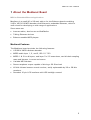
1 About the Medianut Board
MP3 for Embedded Ethernet Applications.
Medianut is a small (40 x 98 mm) add-on for the Ethernut board combining
VLSI's VS1001K MP3 decoder with Ethernut's embedded Ethernet, which is
well suited for developing a wide range of applications.
Some areas are:
•
Internet radios, also known as WebRadios
•
Talking Ethernet devices
•
Ethernet enabled MP3 players
Medianut Features
The Medianut board provides the following features:
•
VS1001K MP3 hardware decoder
•
MPEG audio layer 1, 2, and 3, ISO 11172-3
•
MPEG 1 & 2 for all layers, and layer 3’s 2.5 extensions, and all their sampling
rates and bitrates, in mono and stereo
•
Variable MP3 bitrates
•
Stereo earphone output capable of driving a 30 Ohm load
•
40 kHz infrared remote control receiver, easily replaceable by 36 or 38 kHz
receivers.
•
Standard 16 pin LCD interface with LED backlight control
5
Medianut User's Manual
2 Quick Start
This chapter will help you quickly set up and start using the Medianut board.
Prerequisites for Operation
The following hardware items are necessary to run the Medianut board:
•
An Ethernut Starter Kit or an Ethernut Board plus programming adapter and a
straight through serial communication cable with a DB-9 female on one end
and a DB-9 male connector on the other. Your Ethernut board should be
equipped with an ATmega128 (red colored board). It is possible to run MP3
applications on ATmega103 equipped boards (green color), but the lower
performance limits its use and not all function may work as expected.
•
Two straight-through twisted pair cables together with 10 Base-T hub or
switch or a twisted pair cross cable, if you don't got a hub or switch. If you
want to run the Nutpiper Internet Radio, you need a local LAN with Internet
access, typically provided by a router with NAT support.
•
An unregulated power supply matching your local mains. It should supply DC
8-12V, on a standard 2.1 mm barrel connector. The total power consumption
depends on the display used, but 500 mA should do in most cases.
•
A standard PC equipped with Linux or Windows 98/NT/2000/XP, an available
serial COM port and a twisted pair Ethernet adapter card.
•
An AVR development environment, either AVR-GCC for Linux or WinAVR or
ICCAVR for Windows.
•
An active speaker set or a stereo headphone with 30 Ohm minimum
impedance. A high end amplifier with some bulky JBL speakers will do as
well.
•
A standard LCD or LCD-compatible display and a Sony TV remote control
would be more fun and are required to run the Netpiper application sample.
An adapter may be required to connect the LCD. You may also need a tiny
soldering iron to mount two SMD resistors in order to enable LED backlight
control.
•
A 4-bit port to optionally attach a simple keyboard.
6
Medianut User's Manual
Board Installation
1
Remove the board from the antistatic bag. Visually inspect the board to verify
that it was not damaged during shipment.
a
WARNING: As with all computer equipment, the Medianut board may
be severely damaged by electrostatic discharge (ESD). Be sure to take
proper precautions before removing the Ethernut board from the antistatic bag.
2
Setup the Ethernut as explained in your Ethernut hardware manual. Do not
switch on the power supply before attaching the Medianut board.
3
Attach you programming adapter to the Ethernut board.
4
Plug the infrared decoder to the IR socket (near R10) on the Medianut. The
lense of the decoder must point to the board's edge.
5
Attach the speakers or earphones to the Medianut audio output connecter
X9. When using earphones, never put them on while switching on or off your
equipment. Because of the risk of hearing damage, we strictly recommend to
use speakers.
6
Optionally attach the LCD or LCD-compatible display to the Medianut LCD
connector X7.
7
Attach the Medianut to the Ethernut expansion connector. Make sure, that
smaller connector X2 of the Medianut board is placed near the Ethernut serial
port and that both ends do exactly fit to the Ethernut expansion connector.
8
Connect the power supply to the barrel connector on the Ethernut board.
You are now ready to upload your application code to the Ethernut or use the
Nutpiper radio application sample. See the next chapter for a detailed description
of the Nutpiper program.
7
Medianut User's Manual
3 Nutpiper Internet Radio Application Sample
Listening to the worl wide web.
The Nutpiper application turns your Ethernut/Medianut system into an Internet
Radio by using the Shoutcast protocol. The application is still limited and
experimental. For example, there is no other way to add new radio stations than
to modify and recompile the code. Only LCDs with 2 lines and 16 characters
each had been tested and only Sony TV remote controls are currently supported.
So do not expect a full fledged radio but take it as a basis for your own
creativity.
When running on Ethernut 1.3, listening to Internet bitstreams above 56 kBit
may not be possible. With 32 kByte memory, only a fraction of a second is
available for buffering the stream. The new Ethernut 2.0 is equipped with 512
kByte RAM and can even take 320 kBit streams, if the server delivers the MP3
data at a sufficient rate.
Note, that Nutpiper requires Internet access, your local network must support
this.
Network Configuration
If your local network supports DHCP, no code modifications are required to give
it a first try. Nutpiper will query its IP address, network mask and default
gateway from the DHCP server.
If DHCP is not available, you need to edit the file nutpiper.c.
/* Unique MAC address of the Ethernut Board. */
u_char mac[6] = { 0x00, 0x06, 0x98, 0x00, 0x00, 0x00 };
Change this to the unique MAC address of your Ethernut board.
/* Unique IP address of the Ethernut Board. Ignored if DHCP is
used. */
u_long ip_addr = inet_addr("192.168.192.100");
This must be replaced by a unique IP address within your local network. Make
sure, that this address is able to access the Internet.
/* IP network mask of the Ethernut Board. Ignored if DHCP is
used. */
u_long ip_mask = inet_addr("255.255.255.0");
Replace with the IP mask used in your local network.
/* Gateway IP address for the Ethernut Board. Ignored if DHCP
is used. */
u_long ip_gate = inet_addr("192.168.192.3");
8
Medianut User's Manual
This must be replaced by the IP address of the Internet gateway, normally the IP
address of your Internet router.
Radio Station Configuration
In the current version there is no user interface for adding or removing radio
stations. The code comes with various predefined stations, some of which offer
terrible music. To add your own stations, edit the file config.c. When started for
the first time or after a previously erased EEPROM, Nutpiper will not find a valid
configuration in the EEPROM and call the routine ConfigResetFactory(), which
contains several calls similar to
ConfigStation(MAXNUM_STATIONS, "129.217.234.42/128:8000");
Each call adds a radio station to the list and requires two parameters. The first
one is the index of the entry, ranging from 0 to MAXNUM_STATIONS. Any
index from 0 to MAXNUM_STATIONS - 1 will replace that entry. If
MAXNUM_STATIONS is given, the entry will be put the first unoccupied space.
The second parameter specifies the URL without leading http://. In the above
example Nutpiper will connect IP address 129.217.234.42 on port 8000 and
request /128. Btw. it looks like this is a 128 kbit stream, but in fact it's 56 kbit
only. Some time ago this station, which is located at the University of
Dortmund, Germany, and named elDOradio, reduced the bitrate.
You can add upto 128 stations, as long as the whole configuration fits into 3.5
kByte, leaving 19 bytes for each URL parameter excluding the IP address, the
first slash, the colon and the port number. The above sample would consume 3
out of 19 bytes available.
After recompiling and before uploading the code to an ATmega128 board, make
sure, that the fuse "Preserve EEPROM" is off. Otherwise Nutpiper will still load
the old configuration from EEPROM and ignore ConfigResetFactory(). On the
ATmega103 there is no such fuse and the EEPROM is cleared on each chip
erase.
Storing the configuration into the EEPROM is done by pressing the power off
button on your remote control.
Using the Remote Control
Only Sony TV remote controls are currently recognized. The supported code are
defined in the driver dev/irsony.h.
The ten channel buttons 1 to 9 select the radio station entries 1 to 9. If Ethernut
fails to connect the selected station, the display will show the IP address and the
message "not available".
Channel selects plus and minus can be used to select the next or previous entry.
If the connection fails, Nutpiper will automatically try the next or previous entry.
As soon as a station is connected, Nutpiper will start buffering the stream and
start the MP3 decoder as soon as the buffer is filled. On Ethernut 2 this may
take a while and you can force the decoder to start by pressing a volume button.
9
Medianut User's Manual
When Ethernut received a valid ICY header from the server, it will display the
name of the station in the first line of the LCD. If the server provides meta data
(most Shoutcast servers do), the second line will display the stream title,
typically the interpret and the title of the track.
As you may know from other Ethernut applications (or your webbrowser),
connecting a station which is not available may take upto a minute or more.
That's annoying but no solution is available yet.
Pressing power off will display the message "Shutdown" while the current
configuration is stored in EEPROM. When done, the display will be cleared, but
no part of the system will be powered down.
More remote control features are available when enabling the background
scanner.
Scanning Stations in the Background
The code includes a highly experimental part, called scanner, which is disabled
by default. To enable it, uncomment the line
ScannerInit();
in the file nutpiper.c. This will start an additional thread, which scans the list of
stations in the background.
The user may press the Videotext button on the remote control and wlak
through the list of stations using the channel plus/minus buttons. When pressing
the input select button, the radio will switch to the currently displayed station.
Pressing the Videotext button will return to the normal display.
10
Medianut User's Manual
4 Creating Your Own Applications
Make your wildest ideas come true.
As explained in the previous chapter, the Nutpiper application is just an example
for building your own Ethernet enabled MP3 devices. Fortunately almost all low
level functions are provided by Ethernut's operating system Nut/OS. This chapter
contains some basic introduction, more details are available in the Nut/OS API
documentation.
Network API
Ethernut's TCP/IP stack named Nut/Net provides the required socket API. Check
the Ethernut manuals and samples to become familiar with it.
While Nut/OS can map socket I/O to C standard I/O functions like _read() and
fscanf() or _write and fprintf(), these functions are not very usefull for MP3
streaming because of their additional overhead. It is recommended to use the
native Nut/Net TCP Socket API instead, like NutTcpReceive(). These functions
are similar to the BSD socket library.
Segmented Memory Management
MP3 decoding by software requires at least a 32 bit CPU with more than 100
Mips. But even with a hardware decoder like the one used on the Medianut
Board, moving all the data in realtime from a TCP/IP network to the decoder
requires some special techniques to make it work on a tiny 8 bit system.
The key to success is avoidance of data copying. Usually data streams are
moved from the Ethernet Controller to the Ethernet's driver buffer, then moved
to the TCP buffer, again moved to the application buffer and finally from the
application buffer to the MP3 decoder buffer. Some systems may use additional
steps.
Nut/OS tries to avoid these copies. In extreme, the data may be moved directly
from the Ethernet controller to the MP3 controller. In reality this will fail, because
TCP isn't realtime, but playing MP3 is. So at least one buffer stage is required to
compensate the non deterministic arrival of TCP data.
Each packet received is moved from the Ethernet controller into a so called
NETBUF. Each NETBUF is added to a connection specific queue until the
application request data from the connection. For portability reasons and to keep
things simple, the application provides a buffer and calls NutTcpReceive() to get
that buffer filled with application data out of the queued NETBUFs. This is
another copy, but frees the application from dealing with system specific
NETBUF structures.
The smart part is, that Nut/OS offers a special buffer management to avoid the
final copy into the decoder buffer and that the Nut/OS MP3 decoder driver
makes use of this buffer management. As stated, normally the application buffer
is filled by some kind of read statement (first copy) and transfered to the driver
11
Medianut User's Manual
by some kind of write statement (second copy). When using the segmented
memory management, the application will query the driver for buffer space first
and then pass this buffer to the TCP read routine. This way the TCP read routine
will directly fill the buffer of the decoder driver. When this has been done, the
application commits the buffer filled and requests a new one and so on. This
technique is used in the Nutpiper application file player.c inside THREAD(Player).
The important statements are:
mp3buf = NutSegBufWriteRequest(&rbytes);
Requests buffer space for writing, rbytes will receive the number of bytes
available and the function returns a pointer to the beginning of the buffer space.
got = NutTcpReceive(player.psi_sock, mp3buf, rbytes);
Calls the TCP/IP receive routine to copy the application data into the buffer. The
function returns the number of bytes copied, which may be less than the number
of bytes requested.
NutSegBufWriteCommit(got);
The number of bytes filled into the write buffer are commited and hence
available for the driver.
The memory management routines are not interrupt or thread save and currently
support one system wide buffer only. But they are fast and simple to use.
Typical Nut/OS drivers use a very simple interrupt routine which posts an event
to a worker thread. For performance reasons the MP3 decoder driver accesses
the buffer directly within its interrupt routine. Otherwise the decoder may run
out of MP3 data due to the latency between posting an event and waking up the
worker thread. The application has to disable interrupts each time it calls a
segmented memory management API.
While reading this chapter, you may have asked yourself, why it's called
segmented memory. The API can not only handle a continuos memory space,
but also one that is divided into several segments. This is usefull with banked
memory hardware provided by Ethernut 2 boards.
MP3 Decoder Driver
This interrupt driven driver does all the low level handling of the VS1001K chip.
In order to use it, an application must call VsPlayerInit() once during initialization
and VsPlayerReset() each time before playing a stream. As soon as some MP3
data has been filled into the buffer (see previous chapter), the application will
call VsPlayerKick() to start the driver feeding the decoder. From that point on the
driver expects the application to keep the buffer filled. If it runs out of data, the
driver will stop feeding the decoder and the application must call VsPlayerKick()
again as soon as more data is available again. By calling VsGetStatus() the
application can query the status of the decoder. It returns any of the following
values:
12
Medianut User's Manual
-
VS_STATUS_STOPPED Player is ready to be started by VsPlayerKick().
-
VS_STATUS_RUNNING Player is running.
-
VS_STATUS_EOF Player has reached the end of a stream after
VsPlayerFlush() has been called.
-
VS_STATUS_EMPTY Player runs out of data. VsPlayerKick() will restart it.
A call to VsPlayerFlush() mentioned above will move all remaining MP3 data to
the decoder and stop gracefully. In the Nutpiper application this isn't used,
instead the decoder is reset when changing the radio station. When playing
single tracks from some external media or, more important, short samples from
internal memory, you should call it to make sure, that all data left the audio
output before resetting the decoder.
Some additional routines are provided for volume control (zero of maximum
volume!), querying MP3 information (AVRGCC only), setting special decoder
modes (see VS1001K datasheet) or testing the internal decoder memory.
LCD Interface
The LCD driver currently supports HD44780 compatible display controllers only,
but the majority of alphanumeric displays follow this standard.
On the other hand the display support provided by Nut/OS is very comfortable
when compared to other LCD implementations. Except for initialization no special
calls are required, the driver is fully integrated into stdio library and features a
superset of VT52 emulation for cursor and write position control. This makes it
for example very easy to switch from RS232 terminal output to LCD output and
vice versa. See the Nutpiper application for how to use the LCD.
Infrared Remote Control
A first attempt to provide a unified IR driver interface had been made for the
Sony protocol.
In general, decoding IR commands is a very time sensitive task, which easily
conflicts with other realtime demands like MP3 streaming or Ethernet I/O. The
Nutpiper application proofs, that all task could be done on one ATmega128 CPU
concurrently. Ethernuts running on ATmega103 may face problems, though.
The corresponding API interface is very simple. Beside standard Nut/OS device
registration, which initalizes the driver, NutIrGet() is the only routine and will
return the raw code received from the decoder.
13
Medianut User's Manual
5 Functional Hardware Description
This chapter explains the hardware of the Medianut board.
Infrared Decoder Interface
Use a tiny screw driver to attach the infrared decoder, which comes with your
board. The lense should point down when plugging it into the terminal. The
decoder is working optimal with 40 kHz signals, mostly used by Sony. Decoders
for 36 or 38 kHz are available upon request.
MP3 Decoder
Generally the MP3 decoder is connected via two serial busses. The first one, the
data bus, is used to transfer the MP3 data stream from the Ethernut board to the
decoder. This bus will be driven by the Ethernut hardware SPI. The second bus
is used by the Ethernut board to read register contents from and write register
values to the MP3 decoder. Of course, this is a bidirectional bus and has to be
managed by software.
In order to save I/O lines, both busses share the same data line from the
Ethernut board to the MP3 decoder. However, the paranoid designer spent an
additional port bit to control the decoder's hardware reset line.
Note, that all port bits are routed via a 74LVC245 bus driver to convert the
signal levels between the 5 Volt logic of the Ethernut board and the 3 Volt logic
of the MP3 decoder.
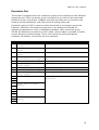
IR Receiver
The infrared receiver requires just a single port bit. Falling and rising edges from
the receiver output will generate interrupts.
Pin
1
2
3
IR Receiver Signal
Data output
Power supply (GND)
Power supply (+5V)
Ethernut Connection
PE4 interrupt 4 input
DC and GND via on-board 5 Volt
regulator
Power Supply
Medianut takes its power supply from the regulated 5 Volts line of the Ethernut
expansion connector and provides its own regulator (IC6) to create the required
3.3 Volts for the MP3 decoder.
14
Medianut User's Manual
Expansion Port
The board is equipped with two connector groups to be attached to the Ethernut
expansion port. Each connector group is located on one side of the board and
divided into two connectors. Address and data bus lines are not routed to the
board to avoid interference with the sensitive analog audio part.
Connector group X1/X2 is used to attach the board in a compact way to the
Ethernut. However, this makes a large part of the board inaccessible for
measuring equipment in case of hardware problems. With connector group
X3/X4 the board can mounted in a 90° angle, which makes it possible to easily
access all parts on both boards. This is very useful for tracing hardware
problems. By default, X3 and X4 are not mounted.
Pin MP3 Decoder Signal
1 DREQ: Data request
output
2 DCLK: Data input clock
input
3 SDATA: Serial data
input
4 BSYNC: Byte
synchronization input
11 XCS: Chip select input
12 SCLK: Control bus
clock input
13 SI: Control bus input
14 SO: Control bus output
26 XRESET: Asynchronous
reset input
18 AGND: Analog ground
21
25
19 AVDD: Analog power
23 supply
6
10
27
5
9
28
Ethernut Connection
PE6 interrupt 6 input
PB1 (SCK) output
PB2 (MOSI) output
PB5 output
PB4 output
PB0 output
PB2 (MOSI) output
PB3 (MISO) input
PB7 output
DC and GND via on-board 3.3 Volt
regulator
DGND: Digital ground
DVDD: Digital power
supply
15
Medianut User's Manual
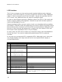
LCD Interface
The 16 pin connector can be used to attach standard alphanumeric displays.
However, most LCDs require a 14/16 pin single line connector while Medianut
offers a 16 pin connector with 2 lines of 8 pins. 14 pins are typically used for
LCD control, two additional lines are used for backlight supply.
In order to save Ethernut port pins, Medianut drives the LCD in 4 bit mode and
doesn't support reading LCD registers. Instead one port bit has been spend to
switch the backlight on or off.
Display backlights differ and you need to check your datasheet before enabling
this feature. Carefully check the schematics for correct polarity and either mount
R13 and R14 (most common) or R12 and R15 (reverse polarity). While R14 and
R15 are 0 Ohm and may be replaced by a simple wire, the values of R12 and
R13 require some calculation first to fit your display.
In most cases the LCD will not show any characters when used with Medianut
for the first time. You need to adjust the potentiometer R16 for optimum
contrast.
In any case we recommend LCD compatible VFDs. Allthough costly, these are
very bright displays with high contrast and do not require backlit supply or
contrast adjustment.
Pin
1
2
3
4
6
7
8
9
10
11
12
13
14
15
LCD Signal
Power supply (GND)
Power supply (+5V)
Contrast adjust
L = Instruction
register
H = Data register
Read/Write control
L = Write to LCD
H = Read from LCD
Enable (data strobe)
Data line bit 0
Data line bit 1
Data line bit 2
Data line bit 3
Data line bit 4
Data line bit 5
Data line bit 6
Data line bit 7
Backlight supply +
16
Backlight supply -
5
16
Ethernut Connection
DC and GND via LCD on-board regulator
None
PE2 output
None, tied to GND
PE3 output
None, tied to GND in 4-bit mode
PD4 output
PD5 output
PD6 output
PD7 output
DC and GND via on-board 5 Volt
regulator and power MOSFET controlled
by PB6 output
Medianut User's Manual
Keyboard Interface
The keyboard is currently not supported by the software, but may be useful for
your own application. Four switches may be attached, each of which will
connect one of the four lower port bits of port D to ground when pressed.
Audio Output Connector
The stereo output may be connected to an earphone, an amplifier line input or
active speakers. It is capable of driving a 30 Ohm load.
Please be carefull when using earphones, always remove them from your ears
before attaching or detaching connectors, playing around with untested software
or switching on and off the power supply. Even with the tiny amplifier of the
Medianut you can severly damage your hearing. Tiny earplugs are more
dangerous than larger headphones. Professionals prefer to use speakers while
developing audio hardware and software.
Scanner Interface
This interface is used with egnite's record shop system. If you are an owner of a
music shop chain, you may be attracted. Call us or send us an email for more
interesting information. Otherwise simply ignore it, it's not there.
17
Medianut User's Manual
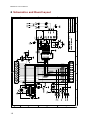
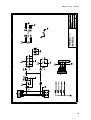
6 Schematics and Board Layout
18
Medianut User's Manual
19
Medianut User's Manual
20
Medianut User's Manual
21
egnite Software GmbH
Phone+49 (0)2323-925 375
Westring 303
Fax +49 (0)2323-925 374
44629 Herne
Email:info@egnite.de
Germany
http://www.egnite.de
http://www.ethernut.de