1
SF100 In Circuit Serial Flash Programmer
semiconductor
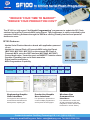
“REDUCE YOUR TIME TO MARKET”
“REDUCE YOUR PRODUCTION COST”
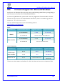
The SF100 is a high speed “In Circuit Programming” programmer to update the SPI Flash
soldered on board or Freescale MCU using Ezport. The programmer is easily controlled by the
computer DediProg Software through the USB bus offering friendly interface and powerful
features to users.
SF100 Features:
•Update Serial Flash soldered on board with application powered
or not
•Update the internal Flash of Freescale MCU using the Ezport
(MCF5223, MCF5221, MCF5213) or the external SPI Flash of
Freescale MCU using the SBF interface (MCF5445, MCF5227)
•Control Application, controller reset and MOSFET isolation status
•Capable of handling two serial flash memories
•Signal conflict protections
•Multi-Programmers Capability
SPI Flash
1Mb
2Mb
4Mb
8Mb
16Mb
32Mb
Program+Verify
(second)
1s
2s
4s
7s
14s
37s
Engineering Graphic
User Interface:
For engineers and experts to
access advanced features for
development, repairing etc.
Production Graphic
User Interface:
For operators in production to
control multiple programmers
and improve the throughput.
Multi Programmers Support
64Mb 128Mb
70s
108s
Windows Dos
Command line
interface:
For customers to control multi
SF100 programmers (SF100
integration, Control SF100 with
Production in Circuit Tester..)
Contact Information: DediProg Technology CO., Ltd. 岱鐠科技有限公司
Web site: www.DediProg.com Sales: sales@dediprog.com Tel: 886-2-2790-7932
SF1
100 Serial Fllash Programmer
SF10
00 Se
erial FFlash
h Proggrammer The In
nnovative solution tto update the Serial Flash on board
rformance
es of low pprice High perf
USB full sspeed supp
port
In Circuit Programm
ming (proogram on b
board SPI Flash)
ash in the socket) Socket Prrogrammiing (progrram SPI fla
ICP conneector to w
work with Serial Flassh soldere
ed on boaard
Friendly a
and powe
erful tool w
with free llife time u
update viaa Website
e Portable programm
mer: SF100
0: (10cm X
X 5cm X 2 cm) Advance
ed I/O con
ntrol
www.ded
diprog.com
m
1 SF1
100 Serial Fllash Programmer
Conteent I. Pro
oduct De
escription
n ................................................... ..................... 3 1.1 Interface descriptio
on ........... ........................................................................ 3 ed to the a
application pin header ................................................... 4 1.2 Connecte
ed to Backkup Boot FFlash ................................................................ 4 1.3 Connecte
II. Pro
oducts Fe
eatures ...................................................... ..................... 5 2.1 USB mode ............................ ........................................................................ 5 d line mod
de ........... ........................................................................ 6 2.2 Command
III. Speecificatio
on ............................................................... ..................... 7 3.1 USB Conn
nector .................... ........................................................................ 7 O characte
eristics .... ........................................................................ 7 3.2 DC and IO
3.2.1 ICP DC and AC characteristics ...................................................................................... 7 3.2.2 ICP timing .................................................................................................................... 11 3.2.3 Host PC
C requireme
ents ................................................................................................. 12 IV. Pro
ogrammiing Perfo
ormance .......................................... .....................13
V. Revvision Hiistory.............................................................. .....................14
Importtant notice:: This do
ocument is p
provided ass a guide lin e and mustt not be discclosed withoout consent of DediPrrog. Howeveer, no respo
onsibility is assumed fo
or errors tha
at might apppear. DediPrrog reservess the right to make anyy changes to
o the product and/or thhe specificaation at any tim
me without notice. No p
part of this document may be cop
pied or reprroduced in aany form or by any meeans withou
ut prior writtten consen
nt of DediPrrog. www.ded
diprog.com
m
2 SF1
100 Serial Fllash Programmer
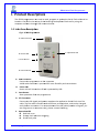
I. Prroduct Descrription
n Thee SF100 proggrammers aare used to read, progrram or upda
ate the Seri al Flash soldered on boaard or insertted in the so
ocket of thee DediProg Backup Boo
ot Flash toool by using the com
mputer softw
ware througgh USB com
mmunication
n. 1.1 Intterface d
descriptio
on Fig 1: SF1
100 Program
mmer A. USB Con
nnector B. Power LEED C. Start But
ton E. Operaation LED D. ICP Conn
nector A. USB Conn
nector Connect tthe program
mmer to thee computerr. A USB cable extensio
on is providded for more flexibility and convennience. B. Power LEED Power LEED will shine
e when SF1000 is powerred by USB.
C. Start button Start opeerations from
m the progrrammer D. ICP Conne
ector Connect tthe SPI sign
nals and pow
wer supply tto the appliication Seriaal Flash via a flat cable. The flat cable is flexible aand convenient to man
nipulate, an d can be ch
hanged easily beffore connecction. For cuustomizatio
on of the ICP
P‐cable (num
mber of signals, pin out assignment or co
onnector sizze), please contact Ded
diProg. E. Operation
n LED Red Led: error Oran
nge Led: ope
eration on ggoing Greeen Led: passs www.ded
diprog.com
m
3 SF1
100 Serial Fllash Programmer
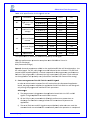
1.2 Co
onnected
d to the a
applicatio
on pin he
eader Thee SF100 proggrammer haas been dessigned to meet the stro
ong and groowing demaand of serial flash users to prograam and upddate the me
emories sold
dered on booard during manipulatio
on or repairing with higgh performaance and devvelopment, production,, and field m
low cost. Beforre trying to update thee Serial Flash
h on Board, be sure thaat the SPI co
ontroller and
d the applicaation are co
ompatible w
with the In C
Circuit Progrramming m
method to avvoid any he programmer. conflict with th
Ded
diProg has p
published Application N
Note to help
p designers to implemeent the ICP method and
d will be pleased to ansswer to any of your que
estions on tthis subject.. ected to thee applicatio
on pin heade
er Fig 2: SSF100 conne
onnected
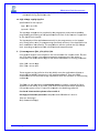
d to Backkup Boot Flash 1.3 Co
Thee software p
provided witth the SF1000 has been developed to offer a ccomplete po
ortfolio of feeatures with a friendlyy and simplee interface tto not require any techhnical experrtise. SF100 can also be used together withh DediProg backup boo
ot flash moddules so thaat it boot from thhe backup fflash located in the bacckup boot flash forcces the appllication to b
mod
dule instead
d of the sold
dered SPI fl ash on the application. Thee backup serrial flash can then be a ccessed at any time with the SF1000 without any possible conflicct with the application controller.
Fig 3: Ba
ackup Boot Flash (BBF)) connected
d to SF100 www.ded
diprog.com
m
4 SF1
100 Serial Fllash Programmer
II. Prroducts Features 2.1 USSB mode In U
USB mode, u
user can con
ntrol the prrogrammer operations via a frienddly interface
e. Useer can load aa file, blank check, proggram and verify the target Serial FFlash. Batch
h button provvides an easy way to p
perform mo re than one
e operation in one clickk. Useer can also eedit the bufffer, files an d SPI Flash content and
d compare.. Fig 44: USB Win
ndow interfa
ace To gget more information o
on the softw
ware featurres, please rrefer to our user manual. www.ded
diprog.com
m
5 SF1
100 Serial Fllash Programmer
2.2 Co
ommand line mod
de Useer can quickly perform some repettitive operations just by typing thee command
d on our Dpccmd interfacce or contro
ol programm
mer using o
other softwa
are (compileer or ICT tester). Fig 55: Dpcmd in
nterface www.ded
diprog.com
m
6 SF1
100 Serial Fllash Programmer
III. SSpecifiication
n 3.1 USSB Conne
ector Thee USB conneector type A
A is availablee to commu
unicate with
h the compuuter tool. USB
B Power sup
pply specificcation: Vdd = 5V ±± 5% Idd min = 500mA 3.2 DC
C and IO characte
eristics 3.2.1 IC
CP DC and
d AC chara
acteristics The ICP conn
nector is a 7
7x2 pin headder straightt type with 2
2.54mm pittch. It is use
ed to co
ontrol the aapplication SSPI Flash, a nd if necesssary supply the SPI Flassh, provide the high vo
oltage to th
he SPI Flash,, or reset thhe applicatio
on chipset, etc. Taable 1: SF10
00 connecto
or Pin out:
1 I/O1
I/O4 2
3 I/O2 or CSS2 NC 4
5 Vcc
GND 6
7 CS CLK 8
9 MISO
MOSI 10
11 Vpp/Accc I/O3 12
13 SCL
SDA 14
www.ded
diprog.com
m
7 SF1
100 Serial Fllash Programmer
Taable 2: Description of tthe signals:: Pin
n Num
mber Nam
me of the ssignals Descriptio
on 1,2,33,12 neral Gen
I//O General I/O aree used to co
ontrol option
nal pins of thhe SPI Flash (hold, P) or switch the applicaation to a sp
pecific modee (reset chip
pset or WP
switch OFF MO
OSFET) 33 I//O2 I/O
O2 can also bbeen used ass a second Ch
hip Select (CCS2) to updatte two serrial Flashes on the boaard (option selected frrom the DediProg sofftware). * 44 N
NC Not Connectedd 55 V
Vcc Vccc is used to ssupply the ap
pplication SP
PI Flash 66 GND GN
ND is the ccommon grround share
ed betweenn application
n and pro
ogrammer 77 C
CS SPI chip select oof the appliccation SPI Fla
ash 88 C
CLK SPI clock signal for the appllication SPI F
Flash 99 MISO Datta out from tthe applicatiion memory (master in s lave out) 100 MOSI Datta in of the aapplication SSPI Flash (master out slavve in) 111 V
Vpp 13,14 SCL,, SDA Higgh voltage appplied on th
he SPI Flash tto speed up the program
mming and
d erasing opeerations I2C
C bus reserveed for future use * Available on
n the products with firmw
ware 2.x.x an
nd after A
A. Applicatiion SPI Flassh supply: V
Vcc Specificattion for the ICP Vcc pinn: - Vcc iss set at 3.3V
V by defaultt and can be
e switched tto 2.5V or 11.8V on the hardw
ware version 3 and afteer (hardwarre version can be identtified with tthe firmw
ware version
n V3.xx) - Icc maax supplied = 50mA The appliication SPI FFlash can bee supplied b
by two diffe
erent sourcees: a) by the programmer via ICP V
Vcc pin at 3.3V b) by the application
n according to the SPI FFlash specification B. SPI signaals managem
ment: CS, CCLK, MISO and MOSI The SPI siignals are used to com municate w
with the app
plication SPI Flash with a high frequencyy (24MHZ o
or 12MHZ acccording to the firmware). The freequency can
n be also adjusted on the latesst hardwaree. The signaals are CMOS compatib le and are sswitched in High Im
mpedance w
when not ussed. www.ded
diprog.com
m
8 SF1
100 Serial Fllash Programmer
Taable 3: DC sspecification for SPI siggnals and IO
O Sym
mbol V
Vih V
Vil Ioh P
Parameter High
h Level Inpu
ut Voltage Low
w Level Inpu
ut Voltage High Level Outp
put current Iol Low Level Output current C
Cap Caapacitance TTest conditio
on
Vccc(V)
Io(mA)
2.7V tto 3.6V 2.3V tto 2.7V 1.65V tto 1.95V
2.7V tto 3.6V 2.3V tto 2.7V 1.65V tto 1.95V
33V ‐24mA 2. 7V ‐12mA 2. 3V ‐12mA 1. 65V ‐4mA 33V 24mA 2 .7V 12mA 2 .3V 12mA 1. 65V 4mA Value Unit 2V 1.7V 0.65XVcc 0.8V 0.7V 0.35XVcc 10nF V min
n V min
n V min
n V maxx mA mA mA mA mA mA mA mA nF typ
p This specificaation is relative to indivvidual capab
bility of one
e signal. ESSD high perrformance p
protection ccompliant w
with IEC6100
00‐4‐2 leve l 4: 15kV (air discharge) 8kV (contactt discharge) R
Remark: thee total capaccitance addeed on the application SSPI bus will also depend on the IC
CP cable len
ngth. The ICP cable lenggth must be
e reduced at the minim
mum. The SP
PI flash output buffeer capabilityy (MISO) is l imited com
mpared to th
he programm
mer perform
mances. So
o even if the programm
mer is able tto drive high capacitan
nce, the Seriial Flash soldered on the appliccation will p
probably noot (information read fro
om SPI Flashh will be wrrong). C. Smart managementt of the SPI Flash Vcc a
and SPI sign
nals In order tto minimize
e the impactt of the ICP method on the chipsett and appliccation board, th
he programm
mer suppliees the appliccation Serial Flash withh Vcc and SP
PI signals only during the proggrammer annd Serial Flash operations. Advantagges: a) The p
programmerr is pluggedd on the app
plication board with Vccc OFF and SSPI signals in High Im
mpedance too avoid inru
ush current.. b) All the ICP pins aare protecteed with ESD
D high performance prootections to
o dischaarge the Ele
ectronics chharge before
e the conne
ection and pprotect the appliccation. c) The SSerial Flash V
Vcc and SPI signals are
e provided o
only when thhe user sen
nd the comm
mand and are switchedd OFF autom
matically wh
hen the opeeration is co
ompleted. www.ded
diprog.com
m
9 SF1
100 Serial Fllash Programmer
Thereefore, the programmerr is transparrent for the applicationn and can be kept conneected during applicatioon trials. D
D. High volttage supplyy: Vpp/Acc
Specificattion for the Vpp pin Vpp = 8
8.5V to 12.5
5V Ipp maax = 50mA The Vpp h
high voltage
e can be su pplied by th
he programmer and ussed to speed
d up programm
ming and errasing of thee applicatio
on Serial Flash if this feaature is sup
pported by the Seerial Flash supplier. The Vpp ssupply will be applied aautomatically by the programmerr on the Vpp
p pin only duriing erase, w
write, or proogramming operations and only if the Vpp op
ption has been enaabled on the
e software. The prograammer will a
also controll the Vpp vo
oltage level acccording to th
he Serial Flaash connectted and its sspecificationn. E. I/O manaagement: I//O1, I/O2, II/O3, I/O4
Four geneeral outputs are availa ble on the ICP connecttor for custoom needs. T
The IOs are in HZ state if the
ere is no sofftware operration ongoing even if tthe power iis connecteed. The IOs aare driven hhigh or low when the software is rrunning com
mmand. I/O4, I/O2
2 = driven H
High I/O1, I/O3
3 = driven LLow These outputs can b
be useful to drive Wp, H
Hold, reset the applicattion chipsett, or switch Offf the MOSFFET transist ors in the application b
board. Theyy are CMOS compatib
ble and are switched inn High Impedance when the softw
ware is not e
executing command
ds. e used as a ssecond Chip Select to update a seecond SPI Flash The I/O2 can also be
soldered on the board. In this ccase, I/O2 have to be co
onnected too the appliccation CS2 and tthe option ““Chip 2” hass to be sele
ected in the DediProg ssoftware. For the D
DC characteristics pleasse refer to table 3. ESD high performan
nce protectiion compliaant with IEC
C61000‐4‐2 level 4: 15kV (air discharge) 8kV( conttact discharrge) www.ded
diprog.com
m
10 SF1
100 Serial Fllash Programmer
3.2.2 IC
CP timing The IO has been designe
ed to set thhe applicatio
on in extern
nal program
mming mode
e before applying the SPI signal. They can bee used to re
eset the chipset and appplication, tto drive m
multiplexers and switch
h SPI bus froom application controlller to progrrammer, to turn off M
MOSFET and
d isolate the
e SPI bus whhen program
mmer is working.
This is the beehavior of the IO and SSPI signals o
on our latestt firmware. A
A. If No pro
ogrammer o
operation iss on going
All our SFF100 outputts are equivvalent to higgh impedance. B. When an
n operation is requesteed on the u
user interfacce I/O1
1, I/O2, I/O3
3 and I/O4 aare first swiitched in Lo
ow impedannce I/O1
1 and I/O3 aare driven loow I/O2
2 and I/O4 aare driven hhigh C. 3ms afte
er IO are sw
witched to Lo
ow Impeda
ance, the CS
S, Clock andd MOSI outp
puts are switched
d in low imp
pedance too
o.CS1 and C
CS2 are driv
ven high CS iss driven high
h Clock and MOSII are driven low. D
D. The proggrammer is then readyy for the com
mmunicatio
on with thee Serial Flassh. So design
ner can use I/O3 to res et or switch
h the application in extternal progrramming mode. Ap
pplication w
will have a ddelay of 3mss between I/O3 is driveen low and Programm
mer SPI outtputs are sw
witched from
m High Impe
edance to LLow Impedaance. SPI comm
munication sstarts 6ms aafter I/O3 h
has been driiven low. Fiig 6: IO and
d SPI timing
g www.ded
diprog.com
m
11 SF1
100 Serial Fllash Programmer
3.2.3 H
Host PC req
quiremen
nts The SF100 in
nterface witth IBM comppatible PC'ss through th
he USB 2.0/ 1.1 port. This gives fu
ull compatib
bility with th
he latest PCC's, noteboo
oks and portables. SSystem Requirements:
- PC with Windows X
XP / Vista / 7 / 8 / 8.1
- Hard dissk with at le
east 64 MB free space.. SSystem Inte
erface: - PC conn
nexion ………
….....................……......….............USB
B 2.0/1.1 poort www.ded
diprog.com
m
12 SF100
S
Seriall Flash Prog
grammer
IV. P
Prograammin
ng Perfforman
nce Tab
ble 4: Prograamming and
d verify in U
USB mode
SP
PI Flash De
ensities 8 Mbit 16 Mbit 32 Mbit 64 Mbit
128 Mbitt
256 Mbbit 512M
Mbit
1Gb
bit Program+ Verify V
11s 15s 20.5s 48.5s
94s 157s 297
7s 717
7s W25X80V W25Q16VS
W
W25Q32FVS
W
S W25Q64CV
VW25Q128
8B W25Q25 6FV S25FL5
512S N25Q0
00AA
Refe
erence IC W
SSIG SIG SIG SSIG VFIG
FG AIF0
01 13GSSF40
Notte 1: The meeasurementts are donee with SF100
0 with firmw
ware 5.5.011 and softwaare verssion of 6.0.4
4.28. The te
ested memoories are fro
om a single serial flash manufacturer. Notte 2: new haardware versions with firmware 3
3.x.x allow V
Vpp/Acc higgh speed proggramming if the chip supports it. TThe programming perfformance w
will be bette
er if app
plying Vpp/A
Acc during tthe program
mming or errasing for ch
hips support
rting such fe
eature. www.ded
diprog.com
m
13 SF100
S
Seriall Flash Prog
grammer
V. Reevision
n Histo
ory Datte Version Change
es 17/055/10 V
V1.0 1.
2.
SF100 andd SF200 upd
dated with 3
3 LED and Sttart button. System reqquirementss updated.
03/133/14 V
V2.0 1.
2.
Remove S F200/SF300
0. Software iinterface up
pdated. ology Co., Ltd
L (Taiwan
n)
DediPrrog Techno
4F., No.7
7, Ln. 143, Xinming Rd., Neihu Dist., Taip
pei City 114, Taiwan
T
TEL: 886-2-2790--7932
ology (Shan
ngHai)
DediPrrog Techno
Room 50
03, Block E, No.1618, Yisha
an Road, Shan
nghai, China TEL: 86-21--5160-0157
Technic
cal Supporrt:supportt@dedipro
og.com
prog.com
Sales Support:saales@dedip
dediprog.co
om.dedipro
og.com www.d
on furnished is believed to be accurate aand reliable. H
However, DediProg assumess no responsibility for Informatio
the consequences of usse of such info
ormation or foor any infringe
ement of pate
ents or other rrights of third
d parties which mayy result from its use. Speciffications menntioned in this publication are subject to cchange without notice. This publiccation supersedes and replaces all inform
mation previo
ously supplied.. All rights rreserved Printted in Taiwan. www.ded
diprog.com
m
14 DediProg User Manual
10/2014
DediProg SF Software
User Manual
Version 6.9
© DediProg Technology Co., Ltd 2014 All right reserved.
DediProg SF Software User Manual
Table of Content
I. Introduction ............................................................................................... 3
II. Software Installation Guide ........................................................................ 3
2.1 Operating System Requirement ...................................................................................... 3
2.2 USB Installation ............................................................................................................... 3
III. DediProg SF Software Engineering GUI ....................................................... 9
3.1 Prepare the Environment ................................................................................................ 9
3.2 Identify the Target SPI Flash ......................................................................................... 10
3.3 Tool Bar Description ...................................................................................................... 11
3.4 Edit Window Description .............................................................................................. 13
3.5 Configuration Window Description .............................................................................. 15
3.6 Supported Devices, Software Version, Firmware Version ............................................ 29
IV. DediProg SF Software Production GUI ...................................................... 30
4.1 Search and Select .......................................................................................................... 32
4.2 Batch Config .................................................................................................................. 34
4.3 Single Site programming ............................................................................................... 34
V. DediProg Windows Command Line .......................................................... 35
5.1 Introduction .................................................................................................................. 35
5.2 How to Start .................................................................................................................. 39
5.3 Basic Usages .................................................................................................................. 39
5.4 Basic Switches ............................................................................................................... 40
5.5 Optional Switches ......................................................................................................... 41
5.6 Exit Code........................................................................................................................ 43
VI. Specific Functions (SF600 and SF600Plus) ................................................. 44
6.1 Dual/Quad IO ................................................................................................................ 44
6.2 Hold Pin Status Setting .................................................................................................. 44
VII. Stand Alone Mode (SF600Plus only) ......................................................... 45
7.1 Project preparation ....................................................................................................... 45
7.2 Stand Alone programming ............................................................................................ 49
VIII.Firmware Support for Microsoft Windows ............................................... 50
IX. Revision History ....................................................................................... 51
www.dediprog.com
1
DediProg SF Software User Manual
Important notice:
This document is provided as a guide line and must not be disclosed without consent of
DediProg. However, no responsibility is assumed for errors that might appear.
DediProg reserves the right to make any changes to the product and/or the specification at
any time without notice. No part of this document may be copied or reproduced in any form
or by any means without prior written consent of DediProg.
www.dediprog.com
2
DediProg SF Software User Manual
I. Introduction
This user manual illustrates the usage of DediProg SF Software. The device connected when
using this software can be used together with SF100, SF600, SF60Plus and Backup Boot Flash
kit. Get more information for DediProg products and how to use them.
II. Software Installation Guide
Please refer to our products specification, presentation and application notes on our website:
www.dediprog.com
2.1 Operating System Requirement
Windows 8.1
Windows 8
Windows 7
Windows Server® 2008
Windows Vista®
Support both 32 bit and 64bit OS
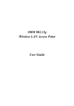
2.2 USB Installation
2.2.1 Insert the installation CD or download the installation software from
www.dediprog.com/download
2.2.2 Execute SFx.x.x.msi file and click next until the installation is finished.
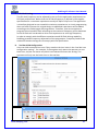
2.2.3 After step 2, connect your computer and DediProg programmer via USB port, A
Hardware wizard will show up as follow.
www.dediprog.com
3
DediProg SF Software User Manual
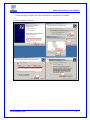
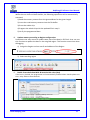
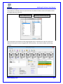
Follow the steps showed in the snap shots below to complete the installation.
A. Win XP operation system:
www.dediprog.com
4
DediProg SF Software User Manual
B. Win Vista & 7 Operation Systems:
www.dediprog.com
5
DediProg SF Software User Manual
C. Win 8 & Win 8.1 Operation Systems:
www.dediprog.com
6
DediProg SF Software User Manual
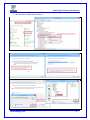
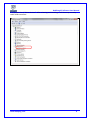
If the USB driver is installed properly, users can find “DediProg SF Programmer driver” under
device manager when the programmer is plugged into the PC.
www.dediprog.com
7
DediProg SF Software User Manual
If no, please check “Other devices”. After selecting and installing, it will show up correctly
under USB controllers.
www.dediprog.com
8
DediProg SF Software User Manual
III. DediProg SF Software Engineering GUI
DediProg SF software is suited for SF100, SF600, SF600Plus and Backup Boot Flash Kit. The
software only can be used to program serial flash memory as well as the downloading
configuration contents to the reference SPI Flash embedded memory in SF600 Plus for stand alone
programming purpose. After the software and USB driver installed, please follow the steps as
below before running the software.
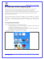
After the software installation, there will be four software icons on your desktop. Icon “DediProg
Engineering” is for the engineering GUI, Icon “DediProg Production” is for the production GUI,
Icon “DPCMD” is for the command line interface and icon “DediProg Help” can show the user
manual.
3.1 Prepare the Environment
3.1.1 Connect the programmer to the PC through a USB cable.
-
For ICP programming, connect the ICP cable to the application (please check the
specification in case ISP header pin out are not known).
-
For socket and stand alone programming, connect the appropriate socket adaptor to
the programmer and insert a serial flash in the socket.
3.1.2 Double click the DediProg software icon on your desktop.
www.dediprog.com
9
DediProg SF Software User Manual
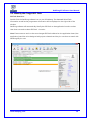
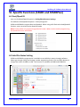
3.2 Identify the Target SPI Flash
SPI Flash Detection
Double Click the DediProg software icon on your PC desktop. The detected Serial Flash
information as well as the programmer information will be displayed on the right side of the
window.
DediProg software will automatically identify the SPI Flash on the application board or socket.
User does not need to select SPI Flash’s location.
Note: If user wants to work on the second target SPI Flash soldered on the application board, the
application board has to be designed with proper schematic and the pin outs have to match with
DediProg ISP pin outs.
www.dediprog.com
10
DediProg SF Software User Manual
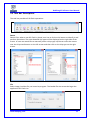
3.3 Tool Bar Description
The tool bar provides all SPI Flash operations.
Detect
Detect Chip: when a new SPI Flash is placed, user has to click on this button to identify it and
perform operations. The auto detected chip types will be displayed on the right side of the
screen. In case user would like to manually select a chip type, he/she can move the mouse
over the chip manufacturer on the left screen and then click on the chip type on the right
screen.
File
Select image: load the file you intend to program. The loaded file size cannot be larger the
application SPI Flash size.
www.dediprog.com
11
DediProg SF Software User Manual
Blank
Blank check: check if the target serial flash is Blank (All Erased)
Erase
Erase SPI Flash: Erase the full content in a Serial Flash. After “Erase” the target serial flash
shall be blank.
Prog
Program: Program the selected image into the Serial Flash
Verify
Verify the checksum value of the selected image and the programmed Serial Flash content
Batch
Batch operation: The programmer will perform a pre-configured set of operations such as
(reload file + erase + program + verify) all together in one click. The configuration can be set
by clicking on the “Config” button. The configuration will not be changed until it is reconfigured.
Press start button can do batch function when user run the SF software.
Edit
When click on Edit, the programmer will by default display the selected file content. User can
click on “read” to read and display the chip contents. See “Edit window description” for more
details.
Config
This allows users to configure advanced settings. See “advanced settings window description”
for more details
Load Prj
Load the existed project to execute the programming operation.
Save Prj
Save all programming settings to a project file for reducing re-setting action.
Download Prj
SF600Plus only, please refer to Chapter 7- VII. Stand Alone Mode (SF600Plus only).
www.dediprog.com
12
DediProg SF Software User Manual
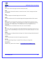
3.4 Edit Window Description
SPI Flash content display:
In the edit window, file contents and chip contents can be displayed in the same time so that
user can make the comparison. By default the selected file contents are displayed once the
user enters into the edit window.
The user can click on “Open” if another file contents are to be shown. The user can click on
“Read” in order to read the chip contents are display them on the edit window as well.
Checksum of file contents and chip contents are displayed.
www.dediprog.com
13
DediProg SF Software User Manual
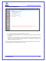
The difference between file contents and chip contents are highlighted with the “Red Fonts”.
User can click on the “next difference” button to search for the next different content
between the chip and the file contents.
Chip buffer to file
This will save the chip contents into a user named binary file.
File buffer to file
File buffer can be modified in real time. This button will save the file buffer contents into a
user named binary file.
www.dediprog.com
14
DediProg SF Software User Manual
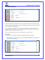
3.5 Configuration Window Description
This feature allows users to configure advanced settings
3.5.1 Batch Operation Option
A.
Update a Whole file with Blank check
When user clicks “Batch”, the following operations will be automatically executed:
1) Read the memory content
2) Blank check (check if Chip is erased)
3) Erase the whole memory if not blank
4) Program the whole memory with the file
5) Verify if the memory content is identical with the programmed file.
www.dediprog.com
15
DediProg SF Software User Manual
B.
Update a Whole file without Blank check
When the user clicks on Batch button, the following operations will be automatically
executed:
1) Erase the whole memory
2) Program the whole memory with the file
3) Verify if the memory content is identical with the programmed file.
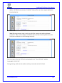
C.
Update memory only on sector locations with contents difference or Smart
update
User can select the sector locations to have the file programmed.
- Update start from address (Hex):
To program a whole file starting from address 0 of a chip.
- Update up to address (Hex):
To program a whole file, ending at the last address of a chip. The default ending
address will automatically calculated by the software according to memory size.
When the user clicks on Batch button, the following operations will be automatically
executed:
1) Read the memory content
2) Compare the memory content from the given address with the file at the 64KB
sector base
3) Erase only the 64KB sectors with some differences
4) Program only the erased sectors with the file data of the corresponding address
5) Verify the data on the updated 64KB sectors
Smart Update can be used in the following cases:
-
A small file can be programmed or updated at a given address without any
change on the rest of the memory (local update).
-
A file with only minor change compare to the memory content can be quickly
updated. The sectors without difference are kept unchanged.
Remark:
The file data which are identical with the target memory but with an address shift
(after compilation) will be interpreted as different and will not benefit of the Smart
update advantages.
www.dediprog.com
16
DediProg SF Software User Manual
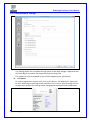
D. Update memory and keep one protected area unchanged
When the user clicks on Batch button, the following operations will be automatically
executed:
1) Read the memory content from the given address for the given length
2) Insert the read memory contents into the file buffer
3) Erase the whole chip
4) Program the whole chip with the updated file in step 2
5) Verify the programmed data
E.
Update memory according to Region configuration
Sometimes user only wants to update some part of the data in SPI Flash. User can use
this function to update the data in the assigned region. This function saves time when
debugging.
1) Assign the Region and set start & end address of the Region.
2) Select working region
F.
Enable Freescale EzPort MCU & Send the DIV value (Hex)
If the box is checked, the programmer will automatically enable EzPort. Details please see
the « Help EzPort User Manual»
www.dediprog.com
17
DediProg SF Software User Manual
G.
Send Specific Data
If the box is checked, the software will load and send the engineering SPI sequence defined
and saved in the “Engineering Mode” Configuration window. This option allows user to create
his/her own SPI instruction.
H.
I.
Identify Chip
If the box is checked, the software will identify before operation starts.
Reload file each time
If the box is checked, the software will load the same file from the source destination each
time before the batch operations (refresh). This option is helpful when another software
update the file in parallel (like compiler).
J.
Require Verification after completion
If this box is checked, the software will verify the contents between the source file and the
programmed Serial Flash contents after the batch operations.
www.dediprog.com
18
DediProg SF Software User Manual
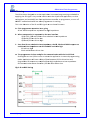
Methods Comparison:
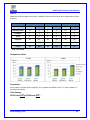
Case 1:
64Mb Serial flash update with 64Mb file totally different. Memory has been previously
programmed and need to be totally erased.
Function
Update with BC
Update without BC
Smart Update
Model name
SF100
SF600
SF100
SF600
SF100
SF600
Memory Read
12
5
x
x
12
5
Compare
1
1
x
x
1
1
Erase
9
9
9
9
14
35
Program
36
33
36
33
47
61
Verify
13
6
13
6
13
6
TOTAL
71
54
58
48
87
108
Time unit: second
Comparison Chart
SF100
SF600
Conclusion:
If the memory needs to be completely erased for a file update, the “Update without Blank
Check” is the optimum choice.
Time Saving:
SF100 save 33%; SF600 save 55%
www.dediprog.com
19
DediProg SF Software User Manual
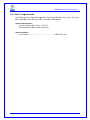
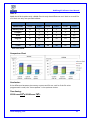
Case 2:
64Mb Serial flash programming with a 64Mb file. Memory has never been programmed (from
supplier).
Function
Update with BC
Update without BC
Smart Update
Model name
SF100
SF600
SF100
SF600
SF100
SF600
Memory Read
12
5
x
x
12
5
Compare
1
1
x
x
1
1
Erase
0
0
9
9
0
0
Program
36
33
36
33
46
59
Verify
13
6
13
6
13
6
TOTAL
62
45
58
48
72
71
Time unit: second
Comparison Chart
SF100
SF600
Conclusion:
If the memory is blank (from supplier), the “Update with Blank Check” or “Smart update” is
the optimum choice.
Time Saving:
SF100 save 19%; SF600 save 37%
www.dediprog.com
20
DediProg SF Software User Manual
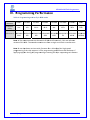
Case 3:
64Mb Serial flash update with a 64Mb file with only data differences on 1 block or a small file
of 1 block size only at a specified address.
Function
Update with BC
Update without BC
Smart Update
Model name
SF100
SF600
SF100
SF600
SF100
SF600
Memory Read
12
5
x
x
12
5
Compare
1
1
x
x
1
1
Erase
9
9
9
9
0.5
0.5
Program
36
33
36
33
0.5
0.5
Verify
13
6
13
6
13
6
TOTAL
71
54
58
48
27
13
Time unit: second
Comparison Chart
SF100
SF600
Conclusion:
If the difference between the memory content and file are small or if the file to be
programmed is small, the “Smart update” is the optimum choice.
Time Saving:
SF100 save 62%; SF600 save 76%
www.dediprog.com
21
DediProg SF Software User Manual
3.5.2 Program Configurations
A. Program a whole file starting from address 0 of a chip
B. Program from specific address of a chip: To program a whole file starting from address
0 of a chip.
C. Program up to specific address of a chip: To program a whole file, ending at the last
address of a chip. The default ending address will automatically calculated by the
software according to memory size.
If the file is smaller than the target Serial Flash, user can define how to fill the rest of the SPI
Flash. By default FFh or 00h if selected in the interface.
www.dediprog.com
22
DediProg SF Software User Manual
3.5.3 Engineering Mode
This function allows users to define their own SPI command and send it directly to the target
SPI flash. This option is powerful as all the not standard SPI commands can be generated even
if not supported by our programmer.
Users can define the data bytes to be sent from the programmer to the SPI Flash and the
number of bytes to be returned. Users can also define if the status register WIP bit has to be
polled to check if the SPI Flash is busy or ready.
Users can save the stream data for future use by click on the “Save” button.
For example:
User wants to write “01 02 03” data bytes at the address “00 00 00” and verify.
First: programmer needs to set the WEL bit by sending the WREN (06h) command to the
SPI Flash as described below:
www.dediprog.com
23
DediProg SF Software User Manual
Second: programmer needs to send the programming instruction “02h” followed by the
address “00 00 00” and the data “01 02 03” and monitor the Status register WIP bit as
described below:
Third: The programmer need to verify the SPI Flash content by sending the Read
instruction “03h” and the address “00 00 00” then read the return bytes from the SPI
Flash (we read 8 bytes in the following example):
The return bytes from the SPI Flash are displayed in the “from SPI Flash” window:
“01 02 03 FF FF FF FF FF”.
The engineering mode can be used to send any instruction to the SPI Flash.
www.dediprog.com
24
DediProg SF Software User Manual
3.5.4 Modify Status Register
This function allows users to modify or read the status register(s) value of the target serial
flash.
Please note each chip has their own command to write status registers.
For chip only has one status register:
- For write: “06h” to set the Write Enable and “01h” and user data” to write the status
register
- For Read: “05h” to read the status register
For chip has two status registers:
- Please refer to the device specification for parameter setting.
www.dediprog.com
25
DediProg SF Software User Manual
3.5.5 Miscellaneous Settings
A.
Vpp Option
This setting allows user to enable the Vpp option so the High voltage is applied on the
SPI Flash Wp pin to reduce the programming and erasing time.
This option can only be enabled on Serial Flash supporting the Vpp feature.
B.
Vcc Option
SF series programmers support 3.5V, 2.5V, and 1.8V Vcc. The default VCC status will
be 3.5V when plug in the programmer without IC on it. User is able to modify the Vcc
configuration and the Vcc setting will be changed and saved until next modification.
www.dediprog.com
26
DediProg SF Software User Manual
C.
SPI Clock Setting
The SPI clock frequency can be adjusted by user to fit the application requirements or
SPI Flash performance. Notice that the SPI Flash frequency is defined in the supplier
specification for a maximum capacitance usually of 30pf or 15pF max. The application
is therefore designed to not exceed this maximum capacitance. In circuit programming
does not fulfill anymore this original design as additional capacitance will be added
according to the cable length and programmer. Therefore, user cannot expect to
program the on board SPI flash according to the maximum frequency of the datasheet
as the SPI flash will not be able to drive such capacitance at such high frequency.
In order to comply with the different capacitance and SPI flash driving capability,
DediProg provides frequency adjustment of the programmer. Frequency needs to be
reduced if the data timings do not comply with the specification.
D.
Tool Bar ICON Configuration
Users can hide some tool bar icons if they unselect the icon items in the “tool bar icon
configuration setting”. For example, if the engineer only wants the operators to use
batch icon, he/she can leaves only batch icon selected and save the setting. The
operators will only see the batch icon on the tool bar.
www.dediprog.com
27
DediProg SF Software User Manual
3.5.6 Flash Option
There’re three kinds of options.
A.
Unprotect block automatically when block(s) protected.
B.
Enable automatically unprotect Individual WP mode
C.
Translate program address to page+offset in standard DataFlash page size.
For example: AT45DB642D program address 0x8000 translate to 0xF820 (page+offset)
www.dediprog.com
28
DediProg SF Software User Manual
3.6 Supported Devices, Software Version, Firmware Version
User can check the Serial flash support list in our web site. This support list is valid for the
latest software and firmware so user will have to check the current software and
firmware version he is using and update it if necessary.
www.dediprog.com
29
DediProg SF Software User Manual
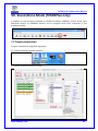
IV. DediProg SF Software Production GUI
DediProg SF software production GUI is only available after the software version 5.x.x. The
production GUI allows users to plug in and operate multiple SF100/SF600/SF600Plus in the
same time.
The new software will remove the old USB driver when it detects such driver during the
installation. New USB driver is required in order to run the software and the driver will come
together with the software CD ROM or it can be downloaded from DediProg website.
www.dediprog.com/download
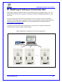
In order to run more than one SF programmer in the same time reliably, USB hub with
individual power supply is highly recommended.
Multi-Programmers Capability for SF series programmers
www.dediprog.com
30
DediProg SF Software User Manual
In order to run production GUI, USB plug in of all the intended programmers is required prior
to opening the software. It is not recommended to add (plug in) or reduce (unplug) any
number of programmers when the software is already opened.
The production software does not provide auto chip detect feature and therefore
“programmer search” and “chip select” are required prior to any other operations.
The production GUI manual will only illustrate the items not covered by the engineering GUI.
Therefore function explanations such as Program, Erase, Blank check, etc will not be repeated
here.
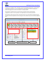
Status window
www.dediprog.com
Programmer Site Status bar
Log Window
31
DediProg SF Software User Manual
4.1 Search and Select
When click on “search”, the software will show programmer type. The default of programmer
type is SF100. Please select the programmer you are using and click Rescan.
Search Programmer:
The found programmers will be listed along with site number. The site number is given by the
Window OS randomly and therefore users can use the “blink”, “up” and “down” button to
adjust the real sequence of the connected programmer. When click on “blink”, the connected
programmer will blink on its green LED once. Users can use this feature to locate the
programmer associated with its site number. For programmers with firmware version after
5.x.x, DediProg will write a serial number in the hardware before shipping out and the serial
number will be displayed in the following screen snapshot.
www.dediprog.com
32
DediProg SF Software User Manual
Select Memory Type:
The production software does not provide auto chip detect feature users will need to select
the target memory manually.
Select a Manufacturer
Manually selected chip type
After the search step and the to-be-programmed chip is selected, the main GUI will have
updated information on the Programmer SITE Status bar, the status window and the log
window.
www.dediprog.com
33
DediProg SF Software User Manual
4.2 Batch Config
By clicking on the “Config” icon, users can access to configure the batch setting.
Users may click on the option “Send Specific Data” for sending the stream data before
reading/writing the device. This customized SPI sequence can be created in the “engineering
interface”.
Users may click on the “Add” or “Remove” for Batch Operation Options directly.
4.3 Single Site programming
Right-click to a specific Programmer Site number, users will have the access of programming
options to the pointed programmer site.
www.dediprog.com
34
DediProg SF Software User Manual
V. DediProg Windows Command Line
5.1 Introduction
The window command line has been designed to control our programmer from the other
software. This feature will be convenient to synchronize the two software in development
(For example: program the memory automatically after the code has been compiled) or in
production (for example: Program automatically the Serial Flash via the ICT tester after the
hardware has been checked).
Command result “log.txt” file will be automatically saved under following folders:
Windows XP:
C:\Documents and Settings\User\Application Data\DediProg\SF100
Windows Vista, Windows 7, Windows 8 and Windows 8.1:
C:\Users\user\AppData\Roaming\DediProg\SF100
This .txt file has to be checked to make sure that the operation has been successful. Time
stamp can also be checked to be sure that the result has been updated with a new value.
Below are the error messages in the log.txt file.
FAIL Identify Fail
FAIL Blank Fail
FAIL Erase Fail
FAIL Program Fail
FAIL Read Fail
FAIL Send Specific data Fail
FAIL Verify Fail
FAIL Unknow
To get more information about these methods please contact DediProg.
www.dediprog.com
35
DediProg SF Software User Manual
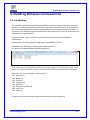
Window DOS command
www.dediprog.com
36
DediProg SF Software User Manual
www.dediprog.com
37
DediProg SF Software User Manual
www.dediprog.com
38
DediProg SF Software User Manual
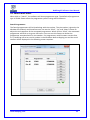
5.2 How to Start
DediProg window dos command line software is executed by the file “dpcmd.exe.” There
are three different ways to run the dos command line.
1. Double click on the “dpcmd” icon on your desktop and type in dpcmd and enter.
2. Change your dos directory to the same location where “dpcmd.exe” is located.
C:\program files\dediprog\SF100
3. Type in the following command to auto directs the dpcmd command to the “dpcmd.exe”
location.
Set path=%path%;”c:\program files\dediprog\SF100
5.3 Basic Usages
1. dpcmd –r "f:\file.bin",
reads the chip and save it into a file "file.bin" in Partition f
2. dpcmd –r STDOUT –a 0x100 -l 0x23,
reads 0x23 bytes starting from 0x100 and display it on the screen
3. dpcmd –u f:\file.bin,
erases and then program file.bin in Partition f into the serial flash
4. dpcmd –p f:\file.bin –a 0x100,
writes file.bin in Partition f into the serial flash starting from address 0x100
5. dpcmd –p f:\file.bin –x 0xaa,
programs file.bin in Partition f into the serial flash and fill the rest area with 0xaa
Remarks: -a, -l only works with -p, -r, -s
Remarks: -x only works with -p
Remarks: space is not needed between the switches parameters. E.g. dpcmd –uf:\file.bin
www.dediprog.com
39
DediProg SF Software User Manual
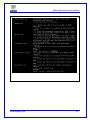
5.4 Basic Switches
-? [ --help ]
Show this help message
--list
Print supported chip list
-d [ --detect ]
detect chip
-b [ --blank ]
blank check
-e [ --erase ]
erase entire chip
-r [ --read ] arg
read chip contents and save to a bin/hex/s19 file
-use STDOUT for the console.
-p [ --prog ] arg
program chip without erase
-u [ --auto ] arg
automatically run the following sequence:
- Read the memory content
- Compare the memory content
- Erase only the sectors with some differences
- Program only the erased sectors with the file data from address
0
-z [ --batch ] arg
automatically run the following sequence:
- check if the chip is blank or not
- erase the entire chip(if not blank)
- program a whole file starting from address 0
-s [ --sum ]
display chip content checksum
-f [ --fsum ] arg
display the file checksum
--raw-instruction arg
- needs to work with a file
issue raw serial flash instructions.
- use spaces(" ") to delimit bytes.
- instructions must be enclosed in double quotation
marks("")
Example:
dpcmd --raw-instruction "03 FF 00 12"
--raw-require-return arg
(=0)
decimal bytes of result to return in decimal after
issuing raw instructions.
- used along with --raw-instruction only.
Example:
dpcmd --raw-instruction "03 FF 00 12" --raw-require-return 1
www.dediprog.com
40
DediProg SF Software User Manual
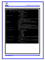
5.5 Optional Switches
(Specify the following switches to change default values):
-a [ --addr ] arg
-l [ --length ] arg
hexadecimal starting address hexadecimal
(e.g. 0x1000),
- works with --prog/read/sum/auto only
- defaults to 0, if omitted.
hexadecimal length to read/program in bytes,
- works with --prog/read/sum/auto only
- defaults to whole file if omitted
-v [ --verify ]
verify checksum file and chip
- works with --prog/auto/load-file only
-x [ --fill ] arg (=FF)
fill spare space with an hex value(e.g. FF),
- works with –prog, --auto only
Specify a type to override auto detection
- use –list arguement to look up supported type.
--type arg
--lock-start arg
hexadecimal starting address(e.g. 0x1000),
- works with –prog/read/sum/auto only
- defaults to 0, if omitted.
--lock-length arg
hexadecimal length of area that will be kept unchanged while
updating
- used along with –auto only.
--blink arg
- 0 : Blink green LED 3 times from USB1 to
USBn (Default)
note: the sequence is assigned by OS during USB plug-in
- 1: Blink the programmer connected to USB1 3 times.
- n: Blink the programmer connected to USBn 3 times.
--device arg
(work with all Basic Switches)
- 1 : activate only the programmer connected to USB1
- n : activate only the programmer connected to USBn
note: if “–device” is not used, the command will be executed
with the same chip type and file on all connected programmer.
--fix-device arg
Fix programmer serial number with programmer sequence.
- instructions must be enclosed in double quotation marks(“”)
Example:
dpcmd –fix-device “1 DP000001”
--list-device-id arg
- 0 : List all ID of programmers from USB1 to USBn (Default)
note: the sequence is assigned by OS during USB plug-in
- 1 : Prompt the device ID of programmer connected to USB1.
- n : Prompt the device ID of programmer connected to USBn.
www.dediprog.com
41
--load-file
DediProg SF Software User Manual
Load a bin/hex/s19 file and compare with memory content
- work with –verify only
Example:
dpcmd –verify –load-file d:\xxx.bin
Miscellaneous options:
Note: The programming operation always uses the default value for command. If users want
to use other setting, must add the wanted option to every command.
-t [ --timeout ] arg (=300) Timeout value in seconds
-g [ --target ] arg (=1)
Target Options
Available values:
1, Chip 1(Default)
2, Chip 2
3, Socket
0, reference card
--vcc arg (=0)
specify vcc
0, 3.5V(Default)
1, 2.5V
2, 1.8V
1800 ~ 3800, 1.8 ~ 3.8V (minimum step 100mV)
(For SF600/SF600Plus only)
- work with –prog and –erase.
Apply vpp when the memory chip supports it
--vpp
--log arg
Record the operation result in given/appointed .txt file
Example:
dpcmd –log F:\LogFilePath.txt
Note: If user didn’t use this command, the operation result will
be recorded in default file “%appdata%\dediprog\SF100\log.txt”
-i [ --silent ]
suppress the display of real-time timer counting
- used when integrating with 3rd-party tools (e.g. IDE)
--spi-clk arg (=2)
specify SPI clock:
2, 12 MHz(Default)
0, 24 MHz
1, 8 MHz
3, 3 MHz
4, 2.18 MHz
5, 1.5 MHz
6, 750 KHz
7, 375 KHz
www.dediprog.com
42
--set-io1 arg (=0)
--set-io4 arg (=1)
DediProg SF Software User Manual
specify Level of IO1(SF100) or GPIO1(SF600/SF600Plus):
0, Low(Default)
1, High
specify Level of IO4(SF100) or GPIO2(SF600/SF600Plus):
0, Low
1, High(Default)
5.6 Exit Code
enum ErrorCode
{
EXCODE_PASS,
EXCODE_FAIL_ERASE,
EXCODE_FAIL_PROG,
EXCODE_FAIL_VERIFY,
EXCODE_FAIL_READ,
EXCODE_FAIL_BLANK, // 5
EXCODE_FAIL_BATCH,
EXCODE_FAIL_CHKSUM,
EXCODE_FAIL_IDENTIFY,
EXCODE_FAIL_OTHERS=99,
};
www.dediprog.com
43
DediProg SF Software User Manual
VI. Specific Functions (SF600 and SF600Plus)
6.1 Dual/Quad IO
User can find Dual/Quad IO option in Config/Miscellaneous Settings.
The default of Dual/Quad IO option is “Always Single IO”.
SF600 and SF600Plus support Dual and Quad IO. When using a SPI Flash with Dual/Quad IO
function, user can select Dual or Quad IO mode.
Note: Socket mode only support Single/Dual IO mode. When use the socket programming
the Quad IO function will disable.
6.2 Hold Pin Status Setting
SF600 and SF600Plus programmer is available to set HOLD pin status through software.
Please go through Config and change it under engineering mode. Click on HOLD button to
change the status of HIGH or LOW. This function is available at SF600 and SF600Plus.
www.dediprog.com
44
DediProg SF Software User Manual
VII. Stand Alone Mode (SF600Plus only)
In addition to the functions provided by SF100 and SF600, SF600Plus further allow users
download project to SF600Plus directly and to program serial flash memories in the
standalone mode.
7.1 Project preparation
Prepare a stand alone programming project.
7.1.1 Open DediProg Engineer software.
7.1.2 Select IC brand and part number.
www.dediprog.com
45
DediProg SF Software User Manual
7.1.3 Load the programing file.
7.1.4 Click “Config” Icon to set programming flow.
Important Notice:
“Identify Chip” is necessary for SF600plus stand alone programming.
Be sure to include “Identify Chip” in programming flow.
www.dediprog.com
46
DediProg SF Software User Manual
7.1.5 Choosing Stand Alone start mode
7.1.6 Save dprj file to PC.
www.dediprog.com
47
DediProg SF Software User Manual
7.1.7 Press “Download Prj” button to download project to SF600Plus embedded memory
7.1.8 Download project successful
www.dediprog.com
48
DediProg SF Software User Manual
7.2 Stand Alone programming
Start Stand Alone programming.
7.2.1 “Start from Programmer Button” mode
Press “Start” button for 2 seconds to run the project in Stand Alone mode.
7.2.2 “Start from COM Port” mode
The Com Port design is for integrating SF600/SF600Plus with customer’s system. All
programmer pin outs (except 5V and NC) are default with Low status. Once
customer/system sends a High signal to trigger START which needs hold for one
second and make the programmer working (i.e. BUSY becomes High status
accordingly), SF600/SF600Plus will also feedback PASS or FAIL result with High signal
after programming.
www.dediprog.com
49
DediProg SF Software User Manual
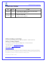
VIII.
Firmware Support for Microsoft Windows
Kindly check the Windows OS version and refer to the following table before you upgrading to
new firmware and software for SF100/SF600/SF600Plus.
If you are using Windows 8.1, please make sure the programmer firmware and SF software
must be the latest version. For older Windows OS version, there’s no need to upgrade the
programmer FW to the latest version.
User can download the latest version on DediProg website.
www.dediprog.com/download
SF100
Windows OS
Current Firmware Version
Upgrade Firmware
Upgrade Software
5.x.xx and later
5.5.02
SF 6.0.4.34
Win8.1
1.x.x to 4.x.x
5.x.xx and later
Please contact DediProg sales
5.5.xx
SF 6.0.4.34
Older versions
1.x.x to 4.x.x
There are no restriction
SF600 / SF600Plus
Windows OS
Current Firmware Version
Upgrade Firmware
Upgrade Software
6.x.x
6.9.0
SF 6.0.4.34
7.x.x
7.1.1
SF 6.0.4.34
6.x.x
earlier than 6.9.0
There are no
restriction
Win8.1 and
other versions
Before Win 8.1
*Please note that support and updates for older hardware versions are no longer available.
www.dediprog.com
50
DediProg SF Software User Manual
IX. Revision History
Date
Version
2010/03/19
5.5
Added: Enable EzPort Function on Configuration; log.txt file
available on Commend line; Blink/Device/Fix-Device on Dpcmd.
2010/04/14
5.6
Added: Update up to address option on Batch and Program
Configuration operation options.
2010/05/10
5.7
Minor improvement
2011/05/18
5.8
1. Added specific function.
2. Added region configuration programming function.
2011/08/26
5.9
Added SF600 Hold pin status setting method.
2012/01/09
6.0
Added SF600 stand alone programming.
2012/12/20
6.1
Revise the CLI detail and add exit codes.
2013/08/23
6.2
1. Added status register-2 function
2. Added the multiple-Dpcmd function.
2013/12/18
6.3
1. Remove part of SF200 and SF300
2. Remove “isolation free” from software
2014/02/25
6.4
New feature for SF600Plus
2014/04/28
6.5
Replenish COM Port feature of Stand Alone mode
2014/05/20
6.6
Modify log saving command
2014/06/04
6.7
1. Add –load-file command for “verify only” feature
2. Updated case study contents and testing time.
2014/08/01
6.8
1. Added IO1/IO4(SF100) and GPIO1/GPIO2(SF600/SF600Plus
setting)
2014/10/28
6.9
www.dediprog.com
Changes
Added chapter VIII. Firmware Support for Microsoft Windows
51
DediProg SF Software User Manual
DediProg Technology Co., Ltd
- Taiwan Headquarter
TEL: 886-2-2790-7932 FAX: 886-2-2790-7916
4F., No.7, Ln. 143, Xinming Rd., Neihu Dist., Taipei City 114, Taiwan
- Shanghai Office TEL: 86-21-5160-0157 FAX: 86-21-6126-3530
Room 503, Block E, No.1618, Yishan Road, Shanghai, China
Technical Support:support@dediprog.com
Sales Support:sales@dediprog.com
www.dediprog.com
Information furnished is believed to be accurate and reliable. However, DediProg assumes no
responsibility for the consequences of use of such information or for any infringement of
patents or other rights of third parties which may result from its use. Specifications
mentioned in this publication are subject to change without notice.
This publication supersedes and replaces all information previously supplied.
All rights reserved
Printed in Taiwan.
www.dediprog.com
52