1
SVM340 Synchronized Video Microscope
User’s Guide
uScope software ©2009-2013 LabSmith.
This manual ©2013 LabSmith. No part of this document may be reproduced without
the written consent of LabSmith.
Table of Contents
1. INTRODUCTION .......................................................... 3
1.1
1.2
1.3
1.4
1.5
2
SVM340 HARDWARE ............................................... 8
2.1
2.2
2.3
2.4
2.5
2.6
2.7
2.8
3
usc files ..........................................................................24
Online and offline operation .........................................24
Upgrading firmware .......................................................24
uSCOPE VIDEO PLAYBACK AND PROCESSING 26
4.1
4.2
4.3
5
Illuminator module ...........................................................9
Optics module ................................................................10
Microscope objective ....................................................11
Fluorescence filter .........................................................12
Base stand ......................................................................13
Front panel controls ......................................................13
Back panel connections ................................................15
Microscope stage...........................................................17
uSCOPE SOFTWARE ............................................. 20
3.1
3.2
3.3
4
New in uScope™ Version 1.04 ........................................3
Package contents ............................................................5
Basic functions ................................................................6
Computer requirements ..................................................6
Installing the software .....................................................8
Video options set-up .....................................................26
VIDEO AND ILLUMINATION TIMING .............................28
Color format set-up........................................................29
VIDEO RECORDING ............................................... 32
5.1
5.2
5.3
5.4
5.5
5.6
5.7
5.8
5.9
Video compression ........................................................32
Recording speed ............................................................33
Buffering .........................................................................33
Pre- and post trigger recording ....................................35
Recording a video ..........................................................35
Snap-shot settings.........................................................36
Deinterlacing ..................................................................39
Time lapse ......................................................................42
Distance indicator ..........................................................43
1
6
PROBES .................................................................. 45
6.1
6.2
6.3
6.4
7
Velocity (PIV) probes .....................................................45
Polygon and Macropixel intensity probes ...................49
Recording probe data ....................................................53
Saving probes ................................................................55
TROUBLESHOOTING............................................. 56
7.1
7.2
7.3
7.4
Getting help ....................................................................56
Video imaging ................................................................57
Video and image quality ................................................60
Dropped frames .............................................................61
SPECIFICATIONS ......................................................... 62
2
1. INTRODUCTION
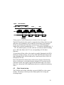
The SVM340 is an inverted fluorescence microscope with built-in video
camera, fluorescence filter, pulsed Light-Emitting Diode (LED) illuminator,
motorized x-y traverse and focusing actuator. It can directly image fluorescent
or non-fluorescent samples on a standard video monitor or video recorder.
In addition, the SVM340 includes an advanced programmable
synchronization unit with four inputs and three outputs for synchronizing
image acquisition to external events.
The basic functions can be controlled by the front panel controls or through
the uScope application software included with the instrument.
1.1
New in uScope™ Version 1.04
Version 1.04 of uScope™ software includes a number of new features and
improvements to existing features:
Macropixel intensity probes
The macropixel probe is a rectangular intensity probe that can be subdivided
into discrete sections for spatially-resolved intensity measurements.
Expanded Time lapse options
The Time lapse option lets you select the frame rate frequency to allow video
taken over a long period of time to be compressed to a small file and played
back at increased speed. The latest version of uScope also allows you to
apply snap shot settings (i.e. flash settings, averaging, black and white level
adjust) to the time lapsed video, essentially compiling a series of snap shots
into a time lapsed video.
Some other relatively new features (implemented in v1.026) include:
Snap-shot settings
The snap-shot feature lets you create a single image consisting of an average
of one or more consecutive images.
3
Motion Limits
Motion limits on the XY stage are useful if you have installed a device on the
SVM (i.e. a chipholder) that may interfere with the stage at its preset limits.
Video compression
Though uScope does not have built-in compression it can now use video
compressors that are installed on your computer. To add compression
functionality, you need to download and install a “codec.” A compatible
codec will also need to be installed on anything that plays the video.
Deinterlacing
Improvements have been made to the deinterlacing method and to the
Deinterlace Settings dialog box.
Buffering
Improvements have been made to the method by which video is buffered to
RAM memory. The newest version of uScope software uses video buffering
for the video recorded live (not from the pre-trigger buffer) so that this video
is also saved without dropping frames.
Recording a video
Improvements have been made to the interface for recording pre- and posttrigger video.
Distance indicator
The Distance Indicator allows you to measure features on your image.
4
1.2
Package contents
The basic SVM340 includes the following items:
• Microscope body + 4 standoffs (feet)
• B&W optics module
• 4-channel illuminator (typically Blue)
• 10X objective
• Delrin sample stage
• standard stage plate (50 mm x 75 mm opening)
• external video capture device
• power, RS232 and S-video cables
• uScope software installation disk
• user’s manual
The following optional items may also be included, if ordered
• additional optics module (i.e. Color, EPI)
• additional illuminators
• 4X or 20X objective
• integrated breadboard sample stage
5
•
•
•
•
chip viewing sample stage (two openings to fit most standard
microfluidic chip sizes)
internal video capture card
Schott glass filter with foam washer
Schott glass filter kit (includes 8 filters and 2 foam washers)
If any parts are missing or damaged, please contact your local dealer or
LabSmith immediately.
1.3
Basic functions
The SVM340 combines an inverted fluorescence video microscope with a
programmable synchronizer and software for on-line image acquisition,
processing and storage. You can use the instrument in several ways:
• As a stand-alone video microscope. Connect the video output from the
SVM340 to an analog video monitor or VCR through the BNC or the
S-video outputs on the rear panel. You can now focus, traverse and
adjust illumination intensity by the controls on the front panel while
observing the image on the monitor.
• As a software-controlled video microscope for automatic or manual
acquisition of video sequences, using the on-line image processing and
storage capabilities of the uScope application.
• As an integrated part of a complex experiment, synchronizing pulsed
illumination, image acquisition and external devices in response to up
to four trigger input signals.
In each of these modes, you can use microscope objectives with magnification
from 4X to 20X, and acquire and store the video output on standard analog
video storage hardware. With the uScope application, you can directly store
the video data on computer disk as .avi files and perform advanced real-time
video processing.
1.4
Computer requirements
The uScope software is designed to stream digitized video sequences directly
to disk, so it is recommended that the computer fulfills the following
minimum requirements:
6
•
•
•
•
•
Windows XP, Vista or Windows 7 or newer
USB2.0 port for the external video capture device or a PCI slot for the
internal video capture card
RS232 port for communication or USB2.0 port and a RS232-USB
adapter
minimum of 1 GB of RAM (4-8 GB recommended)
80 GB hard disk with 12 ms access time (500-1000 GB recommended).
The SVM340 microscope includes a VGA-resolution analog CCD camera
which outputs a standard RS170 monochrome or NTSC color composite video
signal. The video signal is digitized by a DirectX9.0 compliant PCI video
capture card or USB2.0 video capture peripheral, capable of digitizing and
storing uncompressed VGA resolution video on disk.
Many PC video input devices include on-board image compression hardware,
converting the video stream into various compressed video formats. Image
compression standards like MPEG are designed for general visual imagery
and may not be suitable for all types of imagery occurring in microfluidics
device diagnostics, e.g., the images of isolated small particles as recorded in
Particle Image Velocimetry (PIV) experiments. The ability to record
uncompressed video is therefore an important feature of the hardware and
software included with the SVM340.
Uncompressed video streams naturally take up more bandwidth and use more
computer processing power for display and storage, so a powerful computer is
recommended. When used on a newer standard PC with moderately fast CPU
and disk speed, uncompressed video sequences can usually be stored on disk
in real time. If used on slower computers, frames may be lost during recording.
Slower computers may also exhibit a perceptible delay between an imaged
event and its appearance on the computer display.
Also, a large hard disk is recommended for storage of video data. A color
video signal will typically generate 1.6 GB per minute and thus quickly
consume hard disk space.
7
1.5
Installing the software
1.5.1 Installing the video capture card and/or drivers
A video capture card or peripheral USB capture device is required to view and
record the video signal on your computer. If you purchased one of the devices
through LabSmith, a separate instruction manual with the installation
instructions and driver disk will be included with the device. It is always a
good idea to check with the manufacturer’s website to make sure you have the
latest drivers.
If you have purchased a RS232-USB adapter you will also need to install the
drivers for this device. Again, the disk with drivers and instruction manual
will be included with the product.
Your computer may need to be restarted after the video capture or RS232
adapter drivers have been installed.
1.5.2 Installing uScope
If your computer does not already have DirectX9.0 or greater installed you
will need to install it before running uScope. DirectX9.0 is free and available
directly from Microsoft’s website. Most computers will already have this
software installed.
To install uScope, run setup.exe and follow the on-screen directions.
2
SVM340 HARDWARE
The following section describes how to set up your SVM and how to use it
independent of the uScope software.
The SVM340 is shipped with the feet removed to protect the unit during
shipping. They must be installed on the unit before an optics module is
inserted.
Note: The SVM uses a sheet metal chassis to minimize weight, size and cost.
The sheet metal chassis occasionally can have a slight warp that causes
it to rock when the feet are attached. The feet are designed to have
some adjustability to accommodate for this unevenness. This warp
8
does not affect the function of the SVM due to the kinematic design of
the focus stage.
2.1 Illuminator module
The illuminator module consists of four independent LED channels. Two of
the channels (A and B) have 8 LEDs each and two channels (C and D) have 4
LEDs each.
Available LED colors include:
Color
Blue
Green
Red
Yellow
White
Wavelength range
464-476 nm
520-535 nm
615-636 nm
585-595 nm
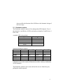
Standard illuminator modules:
Name
Channel A
Channel B
Blue
Blue
LED-B
Green
Green
LED-G
Red
Red
LED-R
Yellow
Yellow
LED-Y
White
White
LED-W
Blue
Green
LED-X
Channel C
White
White
White
White
White
White
Channel D
Blue
Green
Red
Yellow
White
Red
LabSmith can provide customized illuminator modules with any combination
of LED channels.
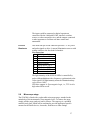
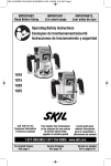
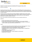
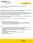
The illuminator module can be removed from the traverse from the top by
pulling the module upwards.
9
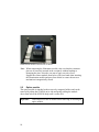
Illumination module installed in SVM340
Note: When reinserting the illuminator module, take care that the connector
pins are all correctly inserted in the receptacle without bending or
damaging the pins. Also take care not to apply excessive force.
Support the camera module from below with your hand when inserting
the illumination module and press from below to ensure the traverse
mechanism is magnetically seated.
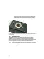
2.2
Optics module
The optics module is attached to the traverse by magnetic holders and can be
removed by tilting the SVM340 on its side and gently pulling the module
down from below the SVM340 body until it comes free.
Important!
10
Turn off power to the SVM340 before removing or inserting an
optics module.
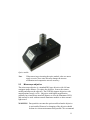
Optics module
Note:
When removing or inserting the optics module, take care not to
apply excessive force since this may damage the traverse
mechanism and compromise traverse accuracy.
2.3
Microscope objective
The microscope objective is a standard DIN type objective with 160 mm
conjugate image distance. To replace the objective, remove the camera
module and unscrew the objective. The SVM340 supports objectives with
magnifications from 4× to 20×. Objectives with higher magnification
generally have insufficient stand-off distance to clear the illuminator LED’s
and can only be used with an external illuminator module or other external
light source.
WARNING: Dust particles can enter the optics module when the objective
is not installed. Removal or changing of the objective should
be done in a clean environment when possible. We recommend
11
that a piece of tape be placed over the objective opening if the
optics module will be stored without the objective installed.
Fluorescence filter installed in an optics module; note: filter washer is placed
on top of filter
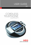
2.4
Fluorescence filter
The fluorescence filter can be installed in the B&W and Color camera
modules. The filter is installed by removing the objective and carefully
placing the filter in the recessed opening. A compliant washer (provided with
the filter) is placed over the filter to keep it secure under the objective.
Note: The EPI camera module is supplied with pre-installed fixed filters that
cannot be removed.
12
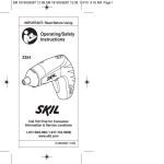
2.5
Base stand
Preset
selectors
Lock indicator
LED
Keypad
Site/light
Toggle buttons
Focus
control
SVM340 front panel
2.6
Front panel controls
Many SVM340 features are accessible through the uScope software. will go
through the uScope application software. You can also, however, access some
important functions directly from the front panel.
The Power button and Power LED are located in the upper left corner of the
front panel. When the power is turned on, the LED will flash green and red
while the system runs its initial tests, and turn green when the tests have
passed.
SiteLight
These buttons toggle between SITE mode and LIGHT mode.
When the SITE button is lit, the four storage buttons A–D
represent four different stored positions, and the keypad controls
the traverse movements. The focus buttons moves the objective
up and down for focusing.
When the LIGHT button is lit, buttons A–D represent the four
13
LED channels, and the keypad up and down buttons control the
intensity of the LED banks selected by the A–D buttons.
A–D
In SITE mode, the buttons A–D represent four stored settings of
the traverse and focus positions and LED intensities.
To recall a stored position, select SITE mode and press and
release a storage button. The traverse will move to the location
and set the four LED intensities to the values of the stored
settings.
To store a traverse position, press one of the storage buttons and
hold it down a few seconds until the button light goes off. This
will store the current traverse position and the LED settings in the
selected storage cell.
Note: There are a total of 10 preset positions available on via the
uScope software.
In LIGHT mode, the buttons A–D represent four LED channels,
labeled A-D. The 24 LEDs in the illuminator module are divided
into four channels, which can be controlled individually. When a
LED bank is selected, the corresponding button lights up. One or
more LED banks can be selected simultaneously by pressing the
one or more of the A–D buttons.
Note: When an EPI Optics Module is installed in the SVM, the
EPI illumination is controlled using front panel button D. In this
case illuminator channels B and D are both controlled by front
panel button B.
Keypad
In SITE mode, the four buttons will move the traverse in the x and
y directions. Pressing a button will start the traverse motor at low
speed, and after about two seconds motor speed slowly ramp up
to high speed. Pressing the button briefly allows single stepping
of the traverse.
Pressing the center button (Stop) will immediately stop any
traverse movement which may be in progress.
When in LIGHT mode, the up/down keys will increase/decrease
14
the intensity of those LED banks which are selected by the A–D
buttons. One or more of the LED banks can be controlled
simultaneously.
Pressing the center button (Stop) with switch off all selected LED
banks.
Focus
up/down
These buttons will move the focus motor up or down to focus the
image. The focus motor will start at slow speed and then ramp up
to high speed.
Lock
indicator
The lock indicator LED on the front panel is green when the
SVM340 is in position.
The Lock indicator LED turns red when the SVM340 is in
motion, e.g. while the traverse is moving to a preset.
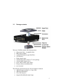
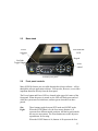
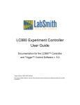
2.7
Back panel connections
Video Output
Digital Inputs and Outputs
Power
The SVM340 back panel
Power
External Illuminator
Communication
Plug the power cable from the back of the SVM340 into a 90
– 240 VAC power outlet.
Communication The female 9-pin D-sub connector is for RS232
communications. This link allows the SVM340 to receive
programming and commands from an external controller, e.g.,
a computer running the uScope application or LabView
15
through the provided serial cable. A USB/RS232 converter
can be used for computers without an RS232 port.
Video Output
The video signal is typically output via the S-video connector.
An analog video capture card (included with the SVM340) is
used to connect the S-video to your computer. It is generally
recommended to use the S-video for best image quality. A
BNC (RS-170) output is also provided for use with monitors
without S-video input.
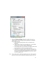
Digital Inputs
and Outputs
The four digital inputs and three outputs on BNC connectors
provide TTL level communication with external equipment.
The inputs can be used to control or strobe the four LED
illuminator channels or to trigger more advanced behaviors.
The outputs are selectable and include video timing
information, motion status information, and several advanced
programmable flags. The inputs and outputs are set from the
menu SVM>Digital Outputs & Inputs:
Digital Output and Input Window
16
The inputs could be connected to digital experiment
controllers like the LabSmith LC880, interlock switches,
sensors, or other external devices, and the outputs connected
to other apparatus to facilitate real-time control and
automation.
External
Illuminator
This male nine-pin D-sub connector provides 5 V DC power
and pulse signals to drive 4 external illumination sources with
settings similar to the four-bank led module.
Pin connections
1 5 V DC (max 3 A)
2 Chassis Ground (0 V)
3 Chassis Ground
4 Chassis Ground
5 Chassis Ground
6 LED A drive (TTL)
7 LED B drive (TTL)
8 LED C drive (TTL)
9 LED D drive (TTL)
The light intensity of the SVM340 LEDs is controlled by
pulse width modulation with a frequency synchronized to the
video signal. Full light intensity means an illumination duty
cycle close to 100%.
LED drive outputs A–D are negative logic, i.e., TTL level is
high when LEDs are off.
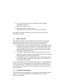
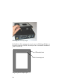
2.8
Microscope stage
The SVM340 is fitted with a replaceable microscope stage, attached to the
main body of the instrument by four magnetic locks. To remove the stage,
simply pull the stage gently up until it releases. The stage top is a polished
stainless steel plate, which can be machined to provide application-specific
mounts for the fluidic device, electrodes, fluid hoses or other fittings.
17
Removing the microscope stage
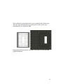
LabSmith also offers an integrating sample stage (A-SVM-Stage-BB) that can
be used to couple the SVM340 microscope to one of LabSmith’s breadboards
(iBB or LS600-CH).
iBB mounting holes
LS600-CH mounting holes
Integrating Delrin sample stage
18
The breadboard is mounted onto four screws installed on the Delrin stage.
The inner stage mounting holes are used for the LS600-CH, the outer
mounting holes are used for the iBB.
Integrating Delrin stage shown assembled with LS600-CH (left) and iBB
(right) breadboards
19
3
uSCOPE SOFTWARE
The uScope software lets you set the functions of the SV340 and control the
video acquisition and on-line processing. It also allows you to recall and
process stored video files. uScope runs on any PC with Microsoft Windows
XP operating system or later.
Note:
The uScope application makes extensive use of the DirectX
software, which is provided by Microsoft Corp. and installed
independently of uScope. If you have installed a local language
version of Windows XP, DirectX will install in the same language.
Consequently, some of the dialog boxes shown below may appear
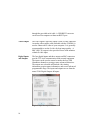
in the language of your windows installation.
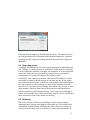
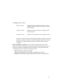
When the uScope software is started a dialog box will pop up that says "Select
a new serial port". Select the COM port that the serial connector is connected
to and click OK. This dialog will keep popping up until you succeed in
communicating with the SVM or you click Cancel (then you work offline and
uScope does not try to send commands to the SVM).
Communications settings dialog box
Note: Some functions are available with the SVM in offline mode.
Manipulation of the stage (x, y, and z) and illuminator settings can be
accomplished via the front panel. Images can be viewed and recorded
20
with the SVM operating offline, however real-time measurements
(PIV and Intensity probes) are disabled.
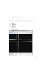
The uScope main window shows the video display (live or saved) as selected
in the Video menu. The following controls are also available:
•
•
•
•
•
•
probes
illumination
focus
x-y traverse
presets
video recording
uScope main window
21
X-Y Traverse. The position indicators to the right and below the video
display indicate the position of the x-y traverse and can be used to move the
traverse. The X-Y traverse has a motion range of 50 mm by 75 mm.
The traverse can also be adjusted using the keyboard arrow keys. Holding
down the shift-key while using the arrow keys slows the traverse to allow fine
adjustment.
Focus. The focus indicator slider bar is located at the top of the main window.
The slider bar can be used to adjust the focus, while the + and – buttons to the
left of the bar are used for fine adjustment. The focus can also be adjusted
using the Page Up and Page Down keys on the keyboard.
Illumination. The LED illuminator channels strobe during each image frame.
The Illuminator control is used to adjust the strobe duration of each channel,
effectively altering the LED intensity.
For certain applications it may be useful to temporarily reduce the motion
limits of the x, y, or focus. The motion range can be reduced by selecting
SVM>Motion Limits… from the main menu. Modification of these limits may
be useful if you have installed a device on the SVM (i.e. a chipholder) that
may interfere with the stage at its preset limits.
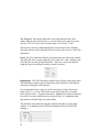
The channels can be adjusted using the controls along the top of the main
window, or by pulling up the LED Pulse Durations window (SVM>LED
Settings...).
22
uScope main window controls
LED Pulse Durations dialog box
When an EPI optics module is installed the forth slider controls the EPI
illumination and channel D is controlled with the Channel B slider/button.
The maximum time duration that can be entered for the pulse duration is
dependent on the camera frame rate, and is equal to 1/f.
Checking the Gang box will cause all LED banks to be adjusted
simultaneously when one slider is activated.
Note: The Illuminator scroll bars do not update when the illumination is
changed via the SVM front panel. If the front panel will be used for
illuminator control, we recommend first setting all illuminator slider
bars to the maximum setting to allow the full range of illuminator
control.
More details on illuminator timing can be found in the Video and Illumination
Timing Section below.
Presets. The presets panel allow saving and restoring up to ten traverse (x, y,
and focus) positions and illumination settings in storage cells A–J. Clicking a
23
button will load the stored preset and adjust traverse position and LED
illumination to the stored values. Checking the Save box first will store the
current setting in the selected storage cell. Sites A-D can also be saved and
accessed from the SVM front panel.
To stop the traverse, click the Stop Motion button
or the center button
on the front panel keypad (the SITE button must first be illuminated).
For descriptions of video recording and probe functions, see sections 5 and
6 below.
3.1
usc files
The uScope software saves the instrument and video settings in a file with .usc
extension. To open a uScope file, choose File>Open, then locate the file on
your hard drive. You can also choose from recently opened files at the bottom
of the File menu.
3.2
Online and offline operation
uScope can work in both online and off-line mode. When on-line, it
communicates with a SVM340, controls its functions and accepts live video
signals from a DirectX compliant video capture card.
When off-line, uScope can open a stored video file for playback and further
processing. uScope will go into off-line mode whenever it fails to locate a
SVM340 on the selected serial port.
3.3
Upgrading firmware
The firmware is the software stored inside the SVM340 in non-volatile
memory and controls the internal functions of the instrument, such as traverse
movements, front panel lamps and buttons, and back-panels inputs and
24
outputs. The firmware is included in the uScope application package and can
be loaded into the SVM340 from within the uScope software.
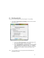
To upgrade firmware to the latest version:
1. Download the newest version of uScope from www.labsmith.com and
install on your computer following the installation procedure described in
the introduction.
2. Connect and turn on the SVM340 and start up the uScope application on
the PC.
3. In online mode, choose SVM>Update Firmware>Update All
4. Click OK when the update dialog box appears
5. Wait while the firmware is updated. You can follow the progress in the
status bar at the bottom of the uScope main window.
6. When the progress indicator reaches 100%, the upgrade is completed.
Important: Do not turn off or disconnect the SVM340 or the PC while the
upgrade is in progress. This may result in loss of communication
with the instrument that requires LabSmith assistance to resolve.
25
4
uSCOPE VIDEO PLAYBACK AND
PROCESSING
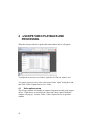
When the uScope software is opened the main window below will appear.
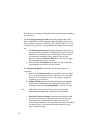
To playback or process a saved video, open the AVI file you want to view.
To capture or process a live video, click cancel in the “Open” dialog box, and
then click Video>Capture/Process Live Video.
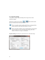
4.1
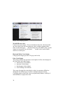
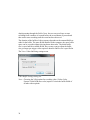
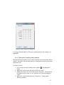
Video options set-up
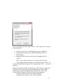
The uScope software will attempt to connect to the most recently used capture
device. If that device is not found, the “Detected Video Capture Hardware”
window will pop up. Or select Video >Video Capture Device to open this
window.
26
Click on the appropriate video capture device. Video capture devices sold by
LabSmith include:
•
•
•
StarTech capture device (SVID2USB2) is listed as: WDM2821
Imaging Source capture device (DFG/USB2 PRO) is listed as:
DFG/USB2pro
Hauppauge internal video card is listed as: Hauppauge WinTV
Capture
Note: If your video capture device is not listed in the Detected
Video Capture Hardware Window, ensure that the device drivers are
correctly installed and the capture device is plugged into a USB
port on the
computer.
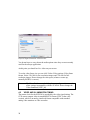
Make sure that either the BNC composite or S-Video connector output of the
SVM340 is connected to an input of the Hauppauge card, and select the
relevant input connector through the Input connector box. Click Video
>Physical Input Connector and select the correct input and ouput:
if using an S-Video cable select SVideo In (typical)
If using the BNC connector select Video Composite
27
Physical Input Connector selection box
You do not have to worry about the audio options since they are not currently
used for the uScope application.
At this point you should see live video on your screen.
To set the video frame size you can click Video>Video options>Video frame
format. Select 320×240 for low-resolution images and 720×480 for fullresolution images. Do not change the color space (whatever comes up,
normally RGB24, is correct).
Note:
The DirectX video controls dialog boxes are of general nature and
allow settings incompatible with the SVM340. Do not change the
Video Standard (NTSC_M)
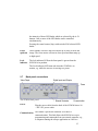
4.2
VIDEO AND ILLUMINATION TIMING
The master clock for the SVM340 is provided by the video signal timing. The
CCD camera outputs video in standard RS170 format (NTSC in the color
version), which is an analog, interlaced format compatible with standard
analog video monitors or video recorders.
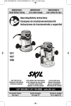
28
Frame
Fields
33 ms full frame
Even
Odd
Even
Odd
Video
LED drive
LED on
(variable)
Timing sequence of the illumination in relation to the video signal
The RS170 interlaced video signal is composed of two fields, called even and
odd fields, each containing every second line of the image. The interlaced
format was defined in the early days of television to avoid flickering TV
images. The even field contains lines 0, 2, 4, …524 and the odd field lines 1, 2,
…525. The field frequency is 60 Hz, with one even and one odd field adding
up to a full video frame each 33.3 ms, corresponding to 30 Hz frame
frequency.
To ensure that all lines of the video signal are equally illuminated, the LED’s
flash twice during an image, once in every field. The LED pulse starts in the
frame blanking period, and its width can be varied from 0 to near 100% of a
field period, 16.6 ms.
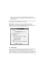
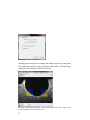
Due to the interlaced readout of the camera sensor, images of fast moving
objects, which move a noticeable distance during the 16.6 ms between two
consecutive fields, may appear jagged at the horizontal edges. See section
below for a discussion of the implications and tools to control the interlacing
effect.
4.3
Color format set-up
The SVM340 can be fitted with either a grayscale (B&W) or color camera
module. The uScope software provides many options for viewing and
recording images.
29
uScope video imaging options
24-bit RGB (true color)
Used for true color images. The user should note that color video data takes
up 8 bits each for the red, blue and green colors, and thus consumes three
times as much disk space
and processing time as the B&W video. If color
images are not needed, the color optics
module can be used in B&W
mode to save disk space.
Black and White Color Scheme
8-bit greyscale images (provides 256 gray scale levels)
False Color Display
The uScope software also provides several options for false color display for
the 8-bit (black and white) images.
• Fluorescence Color Scheme
• Spectrum Color Scheme
• Interferogram Color Scheme
• Food Coloring Color Scheme
The reason for using false color display is that it is sometimes difficult to
distinguish 256 different gray levels on a standard computer monitor.
Converting shades of gray into colors can significantly enhance visibility of
small differences in gray scale value.
30
Invert Color Scheme If checked the selected color scheme will be inverted
(i.e. Black and White Color Scheme will invert black and white pixels. Like
the false color schemes, this option is used to enhance visibility.
Record in False Color Scheme If checked, videos or snap shots will be
recorded in the selected false color scheme. If not checked the false color
scheme will be used for viewing only, and the video will be recorded in
standard black and white.
31
5
VIDEO RECORDING
One of the main features of the uScope application is the ability to record long,
unbroken video sequences without compression. These video sequences are
stored in standard AVI format, so that they can later be viewed by Windows
Media Player or other video playback software, off-line processed by uScope
or other video processing software, compatible with the AVI standard.
To enable uncompressed video recording, uScope makes use of a double
buffering system, described below. The buffering scheme also enables pretrigger recording, enabling you to store a video of what happened before the
trigger instant.
5.1 Video compression
uScope can use video compressors that are installed on your computer, but
does not have any built-in compression. To add compression functionality,
you need to download and install a “codec.” A compatible codec will also
need to be installed on anything that plays the video.
All codecs are not equal. Some compress well. Some compress fast. Avoid
over-compressing the data. The compression occurs when the video is being
captured, so it cannot be “undone” if the results are not desirable. If you plan
to perform PIV on your data we recommend using a lossless compression.
The best-quality video compression takes time. It is often best to save videos
with minimal or lossless compression and later post-process them.
The uScope software contains links to video compression codecs we
recommend (Help>Help install video compressors...).
To save a video with compression, select Video>Use Video Compression…
and the following dialog box will pop up.
32
List of Installed Compressors dialog box
Select the desired compressor from the drop down box. The options listed in
the configure dialog box will depend on the installed compressor. Questions
regarding specific compressor settings should be directed to the compressor
distributor.
5.2 Recording speed
A standard monochrome RS-170 video signal converts into a digital data rate
of 8.9 MBytes/s, which can easily be read into PC RAM memory in real time.
It is also within the capability of modern, fast computers to write to hard disk
in real time at this data rate, provided the computer is not overloaded by
simultaneously executing other disk or CPU intensive tasks.
Color NTSC video signals convert into a data rate of 26.4 MBytes/s, which
can readily be written to RAM memory in real time, but may be too high to
write to hard disk in real time. In that case, some frames scattered throughout
the video sequence are lost, resulting in a stored video sequence with time
intervals of 33.3 ms between most images, but with 66.6 ms, 99.9 ms or some
other multiple of the base frame interval between some individual images.
Such lost frames are called dropped frames. Video sequences with dropped
frames are not suitable for accurate time history analysis, since it is difficult to
know afterwards exactly where frames are missing.
5.3 Buffering
The SVM’s uScope software uses buffering to capture images without
dropping frames. uScope stores digitized video date in a cyclic RAM buffer
simultaneous with the display. Buffering also allows the user to selectively
record events after they occur. For instance, to catch a particular particle or
33
droplet passing through the field of view, the user can set uScope to start
recording from a number of seconds before the record button is pressed and
then wait to start recording until the event has been observed.
The duration of the buffered video sequence depends on the amount RAM set
aside for the buffer. The more RAM installed in the computer, the more buffer
space can be set aside without slowing down other tasks. The initial buffer
size is set to half the available RAM, but you may want to adjust the buffer
size get longer pre-trigger video sequence duration. Buffer size is specified in
The View>Video Buffering settings menu.
Video Buffer Settings dialog box
Note: Choosing the 24-bit option for recording video (Video>Color
Format>24-bit RGB (true color) requires 3-times the buffer RAM of
all other video options.
34
5.4 Pre- and post trigger recording
The figure below illustrates the effect of the buffer size on the pre- and post
trigger recording durations.
Trigger
Stored video
Time
RAM Buffer
Stored video
Time
Disk Buffer
Pre-trigger (top) and post-trigger (bottom) recording
For pre-trigger recording, you save the video sequence occurring before the
trigger, stored in the RAM buffer. With post-trigger recording you save the
video sequence occurring immediately after the trigger and temporarily stored
in the disk buffer. The disk buffer is normally larger than the RAM buffer.
5.5
Recording a video
To record a video, set the time in the Record from box to the desired number
of seconds or drag the slider bar between now and the maximum buffer size.
This sets the time duration recorded from the pre-trigger buffer.
Then either set the For Duration time, or leave it as Unlimited. The duration
time represent the total video duration (pre-trigger buffer + post trigger record
time). If Unlimited video duration is used, the video will record until the
record button is pressed again. The total duration of the video will be the
buffer time plus the newly recorded time (the time the video button is
depressed).
Note: uScope software now uses buffering for the video recorded live so that
this video is also saved without dropping frames.
35
5.6 Snap-shot settings
A snap-shot is a single image consisting of an average of one or more
consecutive images.
Snap-shots are taking by pressing the
or
the lower left hand corner of the main window.
button, both located in
Takes a snap-shot using the predetermined frame averaging and other
options specified in the Snap-Shot Settings (see below)
Takes a snap-shot and frame averages until the button is pressed again.
All other options specified in the Snap-Shot Settings (other than
Number of frames to average) are maintained.
Snap-Shot Settings. The dialog box is opened from View> Snap-Shot Settings.
Snap-Shot Settings dialog box
36
Averaging. Options include
Do Not Average:
Snap-shot will only include one frame. Use this
setting if you have motion and are trying to capture
particle images.
Average x frames:
Number of consecutive frames averaged to form a
single snap-shot.
Average for x ms:
Number of ms averaged to form a single snap-shot.
If you have a little to no motion, increasing the number of frames or time will
improve your signal to noise ratio (for static images the signal to noise ratio
will improve by approximately the square root of the number of frames
averaged).
Black and White level adjust. Use these values to change limits of the video
spectrum. In the full color spectrum 0 represents black and 255 represents white. If
this range is reduced everything below the set black level will appear black and
everything above the set white level will appear white.
None: No black or white level adjust
Auto: image minimum is set to black / maximum set to white
Manual: set minimums (black) and maximum (white) to desired level.
37
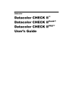
a:
b:
d:
c:
Black and white level adjust example. a: No adjustment; b: black 50 /
white 200; c: black 100 / white 150; d: black 150 / white 150
Flash Settings
Do not strobe: Illuminator will not change when snapshot is taken.
Strobe illuminator: Illuminator settings will change when snapshot is taken.
Selecting LED Settings button opens the LED Pulse Durations dialog box,
where the snap-shot illuminator settings can be selected. After the snapshot is complete the illuminator will switch back to the original settings.
LED pulse duration dialog box
38
This function is useful to prevent photobleaching or heating of your
sample. With this option the illuminator is typically turned off or very low
prior the snap-shot.
Post-strobe delay before recording. Choose the number of frames to skip after the
snap-shot button is selected and before it takes the photo.
File naming. This option allows you to set the default for the type of file,
compressed (jpg) or uncompressed (bmp) and the naming. The files can be
autonamed or you can choose to be prompted each time to choose the file name. This
window can also be access from File>Snap Shot File Saving…
Naming settings for snap-shots
5.7 Deinterlacing
The camera built into the SVM340 runs in standard RS-170 (monochrome) or
NTSC (color) video format at a fundamental frame rate of 30 Hz. As
discussed in section 4.1, the full video frame is composed of two interlaced
fields at a field frequency of 60 Hz. This means that every second line of a full
image is recorded at a time 16.6 ms later than the other half of the lines. As a
39
consequence, fast-moving objects will be recorded with a slight horizontal
blur, which is caused by the image segment in the even lines being shifted
slightly from the image segment in the odd lines.
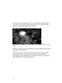
Image of a horizontally moving particle recorded with the SVM340 interlace
camera
Zooming in on such a fast-moving particle reveals the jagged edges caused by
the interlace camera format.
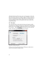
To reduce the effects of the interlacing, uScope includes deinterlace filters,
which will reduce the visual appearance of the blurring caused by the
interlacing by various algorithms. The delinterlace method is selected in the
Video>Deinterlace Video options dialog box.
40
Live Video Deinterlace Video options dialog box
The best deinterlace filter depends on the nature of the video image and
should be chosen by experimentation. A brief description of the three most
common algorithms is given here.
Weave. This method uses three fields in the calculation and works well on
slow moving material but tends to fail on fast moving material.
Bob. The basic bob algorithm uses the most recent field and fills in the lines
between by interpolation. This method detects weaving artifacts in the current
image it uses bob to get rid of them. This method has a tendency to bob rather
too much and gives poor results on fine static images.
Two-frame. This method uses the current frame and the last two to determine
whether to bob or weave a given pixel. This gives better results on both
stationary and moving images than the above two methods but uses more CPU.
41
Although the deinterlace filters improve the visual appearance of the video,
they are not always effective for scientific imagery. All filters are based on
some form of interpolation between frames under the assumption that scene
motion is continuous between frames. When the movies are analyzed by
various algorithms, the effect of the deinterlace filter on the result will be
algorithm-dependent.
5.8 Time lapse
The Time lapse option is used to select the frame rate frequency to allow
videos taken over a long period of time to be compressed to a small file and
played back at increased speed. The time lapse options are set by clicking on
the Time lapse… button(
) at the bottom left side of the main
window. The Time Lapse Settings dialog box will appear.
Time Lapse Settings dialog box
Clicking on the Advanced Settings button will bring up a window that is
identical to the Snap Shot Settings window.
42
Advanced Settings for Time Lapse
Note: the settings selected in this window will only be applied to the video
recordings, the snap shot settings will not change.
The time between images in a time lapse video is dependent on the averaging
time + the wait time between recorded frames. For example, for a recording
rate of 30 fps, if you set the averaging to 15 frames and then set the wait time
to 1 second, then the apparent increase in speed for the video is 45X (15
frames averaged + 30 frames skipped).
For live video recording, advanced time lapse settings also allow you to
control the illuminator strobe to synchronize with the time lapse rate.
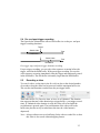
5.9
Distance indicator
The Distance Indicator feature allows you to measure features on your image.
To create an indicator:
Click the Distance Indicator toolbar button
to highlight the
button.
2. With your mouse curser over the image, right click on the mouse and
select New Probe. Click on the image to insert the indicator. The ends
of the indicator can then be moved (click and drag) to the desired
locations.
1.
43
Distance indicator probe
Note: The distance calculation is based on the magnification setting for
the objective. If the magnification setting is incorrect the distance
will be incorrect. If you are evaluating a saved image you will need
to know what magnification was used and adjust the magnification
at SVM>Magnification>….
Distance Indicator display data can be selected by selecting the probe, then
right click and select Properties. The following dialog box will appear.
Distance/angle Indicator Properties dialog box
44
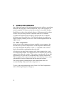
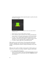
6
PROBES
uScope has sophisticated real-time probe capabilities that allow users to
monitor image properties like color, intensity, variation and video properties
like inferred motion (e.g., particle image velocimetry) in real time. These realtime measurements can be recorded to disk and can trigger real-time actions.
uScope can support as many probes as your computer’s processor can handle.
The two types of probes that can be made in uScope are the Velocity (PIV)
probes and Intensity probes.
6.1
Velocity (PIV) probes
uScope software makes it easy to create probes to monitor flow characteristics.
Each probe can have its own properties; probes are almost always square,
though it is possible to extend the probe in one direction to increase signal-tonoise ratio along that axis.
TIP:
When learning how to use uScope’s PIV probes it is useful to start
with a stable particle flow, or a movie of a stable flow.
6.1.1 Setup
1. Connect the SVM to the computer and turn on both.
2. Launch uScope software.
3. Prepare the microfluidic channel. Fill it out with the buffer and
introduce a sample of polystyrene fluorescent particles.
4. Adjust focus, illumination and flow characteristics.
Alternately, you can also open an existing flow movie by choosing Video >
Process Saved Video Creating velocity probes.
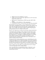
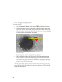
6.1.2 Creating a PIV probe
To create a probe:
1.
2.
Click the Velocity Probe toolbar button
to highlight the button.
With your mouse curser over the image, right click on the mouse and
select New Probe. Bring the mouse to the center point for the new
45
probe and left click the mouse to place the probe. A probe such as the
one below will appear.
New probe showing correlation field, vector arrow and real time
velocity as text
Repeat step 2 to create as many probes as desired.
Once created, the probes can be moved by clicking and holding the
mouse button over the probe and dragging it to the desired location.
5. Click the + and – toolbar buttons to make the probes more or less
transparent. The software will continue to calculate velocity at these
locations even if you make the probes completely invisible.
6. To remove a probe, right click on it and choose Delete.
3.
4.
When you first create a probe uScope will experimentally determine the
fastest FFT algorithm to use. This process may take up to 60 seconds to
complete, at which point the software will begin calculating velocity at the
location.
When you create a probe it will take on the properties of the last probe you
altered. Once created, you can change each probe’s properties individually.
6.1.3 Velocity Probe Properties
1. Double-click on a probe to open the PIV Probe Properties dialog box.
You can also right-click on the probe and choose Properties to open
the dialog box.
46
PIV Probe Properties dialog box
2.
Select the Width and Height of the probe window, the area over
which statistics will be calculated. Some guidelines for setting the
probe window size are:
a. Probes should typically be the same size in both x and y
directions.
b. Smaller probes require less processing power, so use smaller
window sizes to run more probes simultaneously.
c. Increasing the probe size will improve the signal-to-noise ratio;
decreasing the size will increase spatial resolution.
d. If the probe is located in a region of fast flow, the probe size
must be large enough that the correlation does not fall beyond
the window. The Cross Correlation field (see below) can be
an aid in setting the size.
Note: If you cannot achieve sufficient signal-to-noise ratio with a required
probe size you may need to adjust the illumination, particle feed, etc.
47
If the probe is in an area of steady flow then increasing time averaging
may also help.
3.
The Averaging percent per frame values help separate the useful
flow information from the background data by weighing the previous
frames of data versus the current frame. The default values of 95% are
acceptable for most flows. Some guidelines for setting the percentages
are:
a. The Background (mean) percentage determines how much of
the image field is considered “background” based on its steady
presence over multiple frames. Increasing this value increases
the amount of information that is ignored, such as stuck
particles. Check the Subtract Mean box (see below) to apply
this calculation and remove the data.
b. Decreasing the Correlation value improves time resolution;
increasing the value improves noise control.
4.
The Calculations Options control how the flow parameters are
calculated:
a. Enter 1 in the Time interval box to calculate cross correlation
for every sequential pair of frames. Enter 2 to use every other
frame, 3 for every third frame, etc. This option is useful for
examining very slow flows.
b. Subtract Mean subtracts the background (non moving) data
from the flow calculations. The amount of data that will be
subtracted is based on the Background % value (see above).
Note:
If the probe is located in an area of very slow flow then
subtracting the background could delete active particles.
c. Deconvolve Autocorrelation is an advanced option for high
precision measurements. This option deconvolves the cross
correlation by the autocorrelation, which can remove the
effects of blur and particle size such that each particle is treated
as a single point. It is most useful when the signal-to-noise
ratio is extremely high.
48
5.
The Show Field options control which data are displayed for each
probe window:
a. Cross correlation determines how far the particles move
between frames (or between every few frames, based on the
Frames Skipped option). This field is a good diagnostic tool
to help you optimize experiment parameters. The red dot will
move further from the center as the flow velocity increases.
The dot should be small and well defined to achieve the most
reliable measurements. If the flow is too fast the red dot will
move outside of the window, and uScope will not be able to
measure the velocity. In this case, increase the window size,
which will improve the signal-to-noise ratio.
b. Autocorrelation is an indicator of resolution. The mass at the
center of the window will become sharper with smaller
particles and better focus.
c. Mean shows the data that is being subtracted as part of the
Background (based upon the Background % described above).
Showing the Mean can be helpful for highlighting stuck
particles and other anomalies in the flow.
d. RMS is an indicator of the amount of useful signal available
for the calculations.
e. Show Text turns on and off the text-based velocity display.
f. Show Vector displays an arrow in the direction of the flow.
The size of the arrow will change with velocity. You can also
set the Scale to increase or decrease the arrow size.
6.2
Polygon and Macropixel intensity probes
Intensity or polygon probes are used to track the color spectrum or
fluorescence intensity inside a defined region. The advantages of the polygon
probe are that (1) you can make the probe an arbitrary shape to fit your region
of interest, and (2) for color images, the probe can independently track the
intensity of the red, blue, and green signals. The macropixel probe is limited
to a rectangular shape, however it can be broken into multi-pixel arrays to
obtain spatially resolved intensity data. The macropixel probe also allows
time averaging of probe output data.
49
6.2.1 Polygon intensity probes
To create a probe:
1.
2.
Click the Intensity Probe toolbar button
to highlight the button.
With your mouse curser over the image, right click on the mouse and
select New Probe. Click on the image to draw the outline of the probe.
When the shape is defined double click the mouse to close the polygon.
A probe such as the one below will appear.
Intensity probe
3.
4.
Repeat step 2 to create as many probes as desired.
Once created, the probes can be moved by clicking and holding the
mouse button over the probe and dragging it to the desired location.
The shape of the probe can also be modified by dragging the polygon
points to create the desired shape.
Intensity probe data displayed and recorded can be selected by selecting
the probe (left click), then right click and select Properties. The following
dialog box will appear:
50
Polygon Probe Properties dialog box
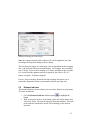
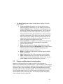
For images from the B&W or EPI optics module only the Gray displays are
applicable.
6.2.2 Macropixel intensity probe properties
Macropixel intensity probes are used when spatially-resolved intensity data is
needed. The probe is divided into an array of sub-probe sections based on the
input pixel size.
To create a probe:
1. Click on the macropixel button on the toolbar
to highlight the
button.
2. Right click on the image and select “insert new probe”.
3. Double click where you would like to place the probe. The probe can
be dragged on the screen to a new position, or resized by dragging a
corner.
4. Right click on the probe and select “Properties...” brings up the
following window.
51
Macropixel Probe Properties
Changing the macropixel size changes the number of pixels per sub-probe.
The probe data can also be time averaged to reduce noise. The following
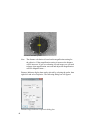
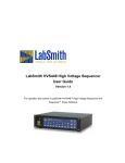
image shows two probes of different pixel size.
Example of macropixel probes. Probe on left had array of 8 x 8 pixel size;
probe on right has 32 x 32 pixel size.
52
6.3
Recording probe data
Data can be recorded simultaneously from all probes. To record data:
1. Choose File >Measurement File Naming to select how the recorded
data will be saved:
Naming settings for new measurements dialog box
a. If you choose Do not auto-name, uScope will prompt you for
a file name and location for each new recording.
b. Choose Auto-name files to automatically name each recording.
Check Append the date, Append the time, and/or Append
counter to add these values to the new file names. An example
of how the name will appear is shown at the bottom of the
dialog box.
Note: You can currently only save the probes in the tab-delineated text
spreadsheet file format.
53
2. To begin recording choose File >Record, or click the Start/Stop
toolbar button. If Autonaming is selected, recording will begin
immediately. Otherwise, recording will begin after you name the file
and click OK.
3. To end recording, choose File > Record or click the Start/Stop button
again.
Probe output file
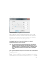
Data from all recorded probes will be output into a single file.
PIV probe data
The PIV data will include four columns for each probe: the X and Y locations
of its centroid, measured from the upper left of the window, and the X and Y
velocity at each point in time. The X/Y location columns will only have
entries in the first row.
Note: The probe data will only be recorded while the video is playing. Snap
shot images or
paused video will not record probe data.
Polygon probe data
The Polygon probe data output depends on the options selected in the Polygon
Probe Properties window. The first two columns are the horizontal and
vertical pixel location of the centeroid, referenced from the top, left corner of
the image. The data columns are listed next and depend on the display
options selected in the Polygon Probe Properties window.
Macropixel probe data
The macropixel probe data contains four columns for each probe.
Macropixel sum from {X,Y}defines the location of the macropixel probe. X
and Y are the horizontal and vertical locations, respectively, of the top left
corner of the probe.
Span:{x, y, n) defines number of pixels in the horizontal (x) and vertical (y)
direction of each sub-probe; and the selected frame averaging (n).
54
The probe data column headings {a, b} are the position of the sub-probe in the
array{horizontal, vertical}, with the bottom left corner sub-probe listed as
position {0, 0}.
6.4
Saving probes
A set of probes can be saved to disk and recalled later:
1.
Arrange the probes and set their Properties.
2.
Choose File >Save Probes As to create a new probe file. Probe
files are saved in the uScope file formate (*.usc).
3.
Select the name and location for the file and click Save.
To recall a stored set of probes choose File > Open.
55
7
TROUBLESHOOTING
7.1
Getting help
This guide is your main source for information on operating the SVM340 and
the uScope software. Check the LabSmith web site (www.labsmith.com) for
user manual updates, application notes and information to help you use the
SVM340.
If you are unable to find the help you need, call the LabSmith technical
support at (925) 292 5161 or send an e-mail to support@labsmith.com. If you
need support, please write down the serial number of your SVM340 (located
on the bottom of the unit) and the version of the software you are using. To
get the software version number, click Help>About uScope in the uScope
main window.
56
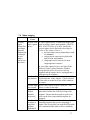
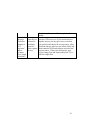
7.2 Video imaging
Problem
Possible
Cause
no video
problem with
signal
video capture
(image does device
not change
when the
illumination
is changed
or your
hand is
waved over
the video)
Resolution
A video capture device is required to image video
with an analog camera optics module (A-RS170BW, A-RS170-Color, or A-EPI). Ensure the
correct capture device has been selected (go to
Video>Video Capture Device...)
•
•
•
StarTech capture device (SVID2USB2) is listed
as: WDM2821
Imaging Source capture device (DFG/USB2
PRO) is called: DFG/USB2pro
Hauppauge internal video card is called:
Hauppauge WinTV Capture
If your video capture device is not listed in the
Detected Video Capture Hardware Window,
ensure that the device drivers are correctly
installed and the capture device is plugged into a
USB port on the computer.
s-video cable S-Video cable must be installed in the back of the
not installed SVM and in the Video Adapter. Check each end
of the cable to ensure the 4 pins of the connector
are intact.
S-video input go to: Video>Physical Input Connector... and
not selected
select S-video for the input
optics
module
installed
incorrectly
not focused
on target or
target not
properly
illuminated
The optics module has two pins to guide it into
place and is held to the SVM focus stage with
magnets. Ensure that the module is squarely in
place on the focus stage and that magnets are
engaged.
If the optics module is not focused on an object it
sometimes appears that you are not getting a
signal. This is especially true with the EPI module
(or a standard module when a filter is installed).
57
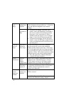
Very dim
video
image
imaging
settings misadjusted
incorrect
excitation or
filter
SVM can’t
focus on
target
target above
maximum
focus range
no EPI
incorrect
illumination optics
module
configuration
EPI
illuminator
turned off
Color
camera
images are
in B&W
Imaging
settings misadjusted
select
Video>Brightness/Contrast/Hue/etc...>VideoProc
Amp and adjust the Brightness and Contrast
settings
• for fluorsecent imaging with B&W optics
module: ensure the illuminator wavelength is
the correct excitation for the fluorescent dye
being used. Also, ensure that if a filter is
installed (under the objective) its wavelength
range is correct for the fluorescent emission.
• for fluorsencent imaging with the EPI optics
module: ensure the EPI optics module has the
correct excitation/emission for the fluorescent
dye being used.
The top focus range of the SVM is limited to
prevent interference between the illuminator
module and the stainless steel stage. If the target
can’t be brought within the focus range one option
is to use an objective spacer to increase the focus
height by 1.25mm. This solution works best when
using an objective with a long working distance
(i.e. 4X) and without the 4-channel illuminator
(i.e. with the EPI Optics Module).
Select View>Camera Configuration and ensure
Epifluorescence Illumination Type is selected.
NOTE: ensure you have an EPI optics module
installed before you change the configuration.
EPI illuminator adjustment replaces the Channel
D adjustment slider/button when an EPI module is
installed (Channel D illumination control is
ganged with channel B)
go to Video>Color Format> and ensure 24-bit
RGB is selected.
go to Video>Properties>Video Proc Amp and
maximize the Saturation setting. Adjust
58
Error
Message
“Failed to
connect to
LUT
converter”
and/or
“Cannot
Give Graph
to Builder”
Brightness, Contrast and Hue to optimize the
image.
incompatible If an incompatible video capture source is selected
video device (such as VDP source) or if you switch between
selected or
capture sources you may get errors, even when
switching
you go back and choose the correct source. Shut
between
down the uScope software, turn off the SVM, and
video capture then restart the SVM and software and select the
devices
correct source. If the errors still persist, go to
Video>Image Size and Format and select 720 x
480 for Output Size.
59
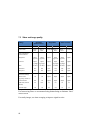
7.3 Video and image quality
Settings
Module
Darkfield
(Fluorescence)
Brightfield
B&W
EPI
B&W or
Fluor.
B&W or
Fluor.
Brightness
adjust
(typ low)
adjust
(typ low)
adjust
adjust
(typ low)
adjust
(typ low)
adjust
Contrast
adjust
(typ high)
adjust
(typ high)
adjust
adjust
(typ high)
adjust
(typ high)
adjust
Hue
no effect
no effect
adjust
no effect
no effect
adjust
Saturation
min
min
max
min
min
max
Sharpness
min
min
adjust
min
min
adjust
White LEDs
(typically channel C)
off
off
adjust
adjust
adjust
adjust
Colored LEDs
max
off
adjust
adjust
adjust
adjust
EPI LED (channel
D/EPI)
n/a
max
n/a
n/a
n/a
n/a
External light
off
off
off
off
on
on
Color Format
Color
B&W
Phase Contrast
24-bit RGB B&W or
Fluor.
B&W
Color
B&W or 24-bit RGB
Fluor.
Video >Brightness/
Contrast/ Hue/etc.
Illuminator Settings
For fast moving flows we recommend using deinterlacing to eliminate “lines”
across screen.
For steady images, use time averaging to improve signal to noise.
60
7.4 Dropped frames
The SVM uScope software uses a buffer as it is recording to minimize
dropped frames. However, if the available RAM isn’t sufficient you may still
experience dropped frames.
Improving available RAM:
•
•
•
•
•
Set the RAM buffer (should be > 500 MB): View>Video Buffer Settings
Close anything running in the background that might be a resource hog: i.e.,
Windows Indexer, Antivirus scan, fetching and scanning emails, automated
backup, etc.
If you are using uScope Probes, close any that aren’t necessary.
Try running without interlacing and/or compression.
Color Format: Running in true color (Video>Color Format>24-bit RGB )
uses 3X more RAM compared to the B&W video options. If true color is not
necessary, chose another option.
61
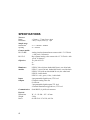
SPECIFICATIONS
Traverse
Range
Resolution
x: 50mm, y: 75 mm, focus: 4mm
x and y: 10 µm, focus (z): 1 µm
Sample stage
Dimensions
Opening
X × Y: 140mm × 200mm
55 × 80 mm
Camera module
RS-170-BW
RS-170-C
Analog, interlaced monochrome camera with 1/3” CCD 640
× 480 pixels, 30 frames/s
Bayer-pattern analog color camera with 1/3” CCD 640 × 480
pixels, 30 frames/s
Objectives
10× plan 0.25/170
4×
20×
Illuminator
modules
LED-B: 3 blue (460 nm, bandwidth 50 nm), one white bank
LED-G: 3 green (560 nm, bandwidth 50 nm), one white bank
LED-R: 3 red (660 nm, bandwidth 50 nm), one white bank
LED-W: 4 white banks
LED-X: 1 red, 1 green, 1 blue, 1 white bank.
Inputs
4 programmable digital inputs, TTL level
Outputs
Composite analog video out
S-video out
3 programmable digital outputs TTL level
4 external illuminator trigger/drivers, TTL level
Communication
Serial RS232, 9 pin D-sub connector.
Physical
Dimensions
Weight
Power
W × L × H: 208 × 267 × 85 mm
2.8 kg
90–240 VAC 47–63 Hz, 100 VA
62