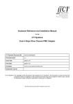
1
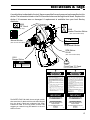
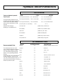
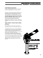
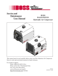
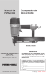
®
User’s Manual
DL09
Hydraulic Drill
This Manual Covers The Following Models:
DL09150
DL09152S
DL09152SN
DL09152SUP
DL09172S
DL09172SN
DL09550D
DL0955001
DL09652
DL0965201
(Depth Rod Not Pictured)
DANGER
SERIOUS INJURY OR DEATH COULD RESULT
FROM THE IMPROPER REPAIR OR SERVICE OF
THIS TOOL.
Copyright © 2002 The Stanley Works
OPS USA & CE Version
25077 7/2002 Ver. 2
REPAIRS AND/OR SERVICE TO THIS TOOL
MUST ONLY BE DONE BY AN AUTHORIZED AND
CERTIFIED DEALER.
Table of Contents
DL09
Hydraulic Drill
SERVICING THE
DL09 HYDRAULIC DRILL:
This manual contains Safety,
Operation, and Troubleshooting
information. Stanley Hydraulic Tools
recommends that servicing of
hydraulic tools, other than routine
maintenance, must be performed
by an authorized and certified
dealer. Please read the DANGER
warning on the cover and the
SAFETY warning below.
Copyright c 2002 The Stanley Works
All rights reserved.
Under copyright law, this document may
not be copied in whole or in part without
the prior written consent of The Stanley
Works. This exception does not permit
copies to be made for others, whether or
not sold. Under the law, copying includes
translating into another language, format
or medium. This copyright notice must
appear on any permitted copies.
2
Certificate of Conformity
3
Specifications
3
General Safety Instructions
4
Tool Decals and Tags
5
Hydraulic Hose Requirements
6
HTMA Requirements
7
Hydraulic Recommendations
8
Operating Instructions
9
Troubleshooting
11
Parts Illustration
13
Parts List
14
Warranty
16
SAFETY FIRST
It is the responsibility of the operator and
service technician to read rules and
instructions for safe and proper operation
and maintenance.
A cautious worker using common sense is
the greatest safety device.
Certificate of Conformity
I, the undersigned:
Winterling, David
Surname and First Names
hereby certify that the construction plant or equipment specified hereunder:
1. Category: Drill
2. Make:
Stanley
DL0955001, & DL0965201
3. Type:
4. Type Serial Number of equipment:
Stamped on tool
5. Year of manufacture:
ALL
Has been manufactured in conformity with- EEC Type examination as shown:
Directive:
Date:
EN792-3
EN28662-1
EN ISO 3744
2001
6. Special Provisions:
Done at:
Approved body:
Self
Date of expiration:
N/A
None
Stanley Hydraulic Tools, Milwaukie, Oregon USA
Date: 2002
Position: Engineering Manager
Signature:
Specifications
Drive Size______ 1/2 in./ 1.3 cm 3-Jaw Adjustable
5/8 - 16 THD Chuck
Pressure Range______1000-2000 psi / 70-140 bar
Flow Range_____________4-12 gpm / 15-45 lpm
Optimum Flow________________ 8 gpm / 30 lpm
System Type__open or closed center, HTMA TYPE I-III
Porting_______________________-8 SAE O-ring
Connect Size & Type___ 3/8 in. NPT Male Adapter
Weight_______________________ 6 lbs. / 2.7 kg
Overall Length__________________ 9 in. / 23 cm
Width_______________________ 3-1/2 in. / 9 cm
Motor____________________________ Integral
Drill Torque___20 ft lbs / 27 Nm at 2000 psi/ 140 bar
Drill Speed__________1000 rpm at 8 gpm/ 30 lpm
RPM Range______________________350-1500
Max. Fluid Temp._____________ 140° F / 60° C
HTMA Class II___________7-9 gpm @ 2000 psi
30Lpm at 138bar
BHTMA CATEGORY
EHTMA Category_____30 lpm @ 138 bar
Weighted Vibration Level____________1.2(m/s2)
Sound Pressure Level_Less than 85 dBA @ 1 m
DL09 TORQUE AND DRILL SPEEDS
TORQUE (proportional to Oil Pressure)
Drill Speed (proportional to Oil Flow)
HYDRAULIC FLOW
DRILL SPEED
USA
METRIC
4 ft-lb @ 500 psi
9 ft-lb @ 1000 psi
14 ft-lb @ 1500 psi
19 ft-lb @ 2000 psi
5 Nm @ 35 bar
12 Nm @ 70 bar
19 Nm @ 105 bar
26 Nm @ 140 bar
3 gpm (11.3 lpm)
4 gpm (15 lpm)
6 gpm (23 lpm)
8 gpm (30 lpm)
10 gpm (38 lpm)
350 rpm
475 rpm
750 rpm
1000 rpm
1250 rpm
3
General Safety Instructions
Always observe safety symbols. They are included for your safety and the protection of the tool.
DANGER
This safety symbol may appear on
the tool. It is used to alert the
operator of an action that could
place him/her or others in a life
threatening situation.
WARNING
This safety symbol appears in these
instructions to identify an action
that could cause bodily injury to the
operator or other personnel.
CAUTION
This safety symbol appears in these
instructions to identify an action or
condition that could result in
damage to the tool or other
equipment.
This tool will provide safe and dependable service if operated in accordance with the instructions
given in this manual. Read and understand this manual and any stickers and tags attached to the
tool and hoses before operation. Failure to do so could result in personal injury or equipment
damage.
A
Operator must start in a work area without bystanders. The operator must be familiar with all prohibited
work areas such as excessive slopes and dangerous terrain conditions.
A
Establish a training program for all operators to ensure safe operations.
A
Do not operate the tool unless thoroughly trained or under the supervision of an instructor.
A
Always wear safety equipment such as goggles, head protection, and safety shoes at all times when
operating the tool.
A
Do not inspect or clean the tool while the hydraulic power source is connected. Accidental engagement of
the tool can cause serious injury.
A
Do not operate this tool without first reading the Operating Instructions.
A
Do not install or remove this tool while the hydraulic power source is connected. Accidental engagement
of the tool can cause serious injury.
A
Never operate the tool if you cannot be sure that underground utilities are not present. Underground
electrical utilities present an electrocution hazard. Underground gas utilities present an explosion hazard.
Other underground utilities may present other hazards.
A
Do not wear loose fitting clothing when operating the tool. Loose fitting clothing can get entangled with
the tool and cause serious injury.
A
Supply hoses must have a minimum working pressure rating of 2500 psi/175 bar.
A
Be sure all hose connections are tight.
A
The hydraulic circuit control valve must be in the “OFF” position when coupling or uncoupling the tool.
Wipe all couplers clean before connecting. Failure to do so may result in damage to the quick couplers
and cause overheating. Use only lint-free cloths.
A
Do not operate the tool at oil temperatures above 140° F/60° C. Operation at higher oil temperatures can
cause operator discomfort and may cause damage to the tool.
A
Do not operate a damaged, improperly adjusted, or incompletely assembled tool.
A
To avoid personal injury or equipment damage, all tool repair, maintenance and service must only be
performed by authorized and properly trained personnel.
A
Do not exceed the rated limits of the tool or use the tool for applications beyond its design capacity.
A
Always keep critical tool markings, such as labels and warning stickers legible.
A
Always replace parts with replacement parts recommended by Stanley Hydraulic Tools.
A
Check fastener tightness often and before each use daily.
A
When working near electrical conductors, always assume that all conductors are energized and that insulation,
Clothing and hoses can conduct electricity. Use hose labeled and certified as non-conductive.
4
Tool Decals & Tags
A model sticker is attached to the tool. Never exceed the flow and pressure levels specified on this
sticker. The information listed on the DL09 model sticker must be legible at all times. Replace this
sticker if it becomes worn or damaged. A replacement is available from your local Stanley
distributor.
28323
“CE” Decal
(CE Models only)
29149
Rotation Direction Sticker
(Not used on all models)
28788
Manual Sticker
®
Model No.
DL09
(Not used on all models)
Stanley Hydraulic Tools
3810 SE Naef Rd
Milwaukie, Oregon 97267
15-45 lpm/4-12 gpm
140 bar/2000 psi
28769
DL09 Model Sticker
RPM Sticker
29148
(Not used on all models)
15211
Danger Sticker
30Lpm at 138bar
BHTMA CATEGORY
DANGER
Failure to use hydraulic hose labeled and certified as
non-conductive when using hydraulic tools on or
near electric lines may result in death or serious
injury.
For proper and safe operation read owners manual
and make sure that you have been properly trained in
correct procedures required for work on or around
ELECTROCUTION
electric lines.
HAZARD
7-10 GPM/ 24-36 LPM
11207
Circuit Type “D” Decal
DO NOT EXCEED 2000 PSI/ 140 BAR
n DO NOT EXCEED SPECIFIED FLOW OR PRESSURE. n USE CLOSED-CENTER
TOOL ON CLOSED-CENTER SYSTEM. n USEOPEN-CENTER TOOL ON OPENCENTER SYSTEM. n CORRECTLY CONNECT HOSES TO TOOL "IN" AND "OUT"
PORTS. n IMPROPER HANDLING, USE OR MAINTENANCE OF TOOL COULD
RESULT INA LEAK, BURST OR OTHER TOOL FAILURE. n CONTACT AT A LEAK
OR BURST CAN CAUSE OIL INJECTION INTO THE BODY. n FAILURE TO
OBSERVE THESE PRECAUTIONS CAN RESULT IN SERIOUS PERSONAL
INJURY.
(Not used on all models)
DANGER
The SAFETY TAG, P/N 15875, shown at right, smaller
than actual size, is attached to the tool when shipped
from the factory. Read and understand the safety
instructions listed on this tag before removal. We
suggest you retain this tag and attach it to the tool
when not in use.
DANGER
1. FA I LU R E T O U S E H Y D RAU L I C H O S E L A B E L E D A N D
CERTI-FIED AS NON-CONDUCTIVE WHEN USING
HYDRAULIC TOOLS ON OR NEAR ELECTRICAL LINES
MAY RESULT IN DEATH OR SERIOUS INJURY.
BEFORE USING HOSE LABELED AND CERTIFIED AS
NON- CONDUCTIVE ON OR NEAR ELECTRIC LINES.
BE SURE THE HOSE IS MAINTAINED AS NON- CONDUCTIVE . THE
HOSE SHOULD BE REGULARLY TESTED FOR ELECTRIC CURRENT
LEAKAGE IN ACCORDANCE WITH YOUR SAFETY DEPARTMENT
INSTRUCTIONS.
2. A H Y D R A U L I C L E A K O R B U R S T M AY C A U S E O I L
INJECTION INTO THE BODY OR CAUSE OTHER SEVERE PERSONAL
INJURY.
A. D O N O T E X C E E D S P E C I F I E D F L O W A N D
P R E S S U R E F O R T H I S T O O L . E X C E S S F LO W O R
PRESSURE MAY CAUSE A LEAK OR BURST.
B. D O N O T E X C E E D R AT E D W O R K I N G P R E S S U R E
OF HYDRAULIC HOSE USED WITH THIS TOOL.
E X C E S S P R E S S U R E M AY C A U S E A L E A K O R
BURST.
C. C H E C K T O O L , H O S E , C O U P L E R S &
C O N N E C T O R S
D A I LY
F O R
LEAKS. DO NOT FEEL FOR LEAKS WITH
Y O U R H A N D S . C O N TA C T W I T H A L E A K M AY
RESULT IN SEVERE PERSONAL INJURY.
D. DO NOT LIFT OR CARRY TOOL BY THE HOSES. DO NOT ABUSE
HOSE. DO NOT USE KINKED, TORN OR DAMAGED HOSES.
3. M A K E S U R E H Y D R A U L I C H O S E S A R E P R O P E R LY
CONN-ECTED TO THE TOOL BEFORE PRESSURIZING
S Y S T E M . S Y S T E M P R E S S U R E H O S E M U S T A LWAY S
B E C O N N E C T E D T O T O O L “ I N ” P O R T. S Y S T E M
R E T U R N H O S E M U S T A LW AY S B E C O N N E C T E D AT
T O O L “ O U T ” P O RT. R E V E R S I N G C O N N E C T I O N S M AY
C A U S E R E V E R S E T O O L O P E R AT I O N W H I C H C A N
CAUSE SEVERE PERSONAL INJURY.
4. D O N O T C O N N E C T C L O S E D - C E N T E R T O O L S T O
O P E N - C E N T E R H Y D R A U L I C S Y S T E M S . T H I S M AY
C A U S E E X T R E M E S Y S T E M H E AT A N D / O R S E V E R E
PERSONAL INJURY.
DO NOT CONNECT OPEN-CENTER TOOLS TO C LO S E D - C E N T E R
HYDRAULIC SYSTEMS. THIS MAY RESULT IN LOSS OF OTHER
HYDRAULIC FUNCTIONS POWERED BY THE SAME SYSTEM AND/OR
SEVERE PERSONAL INJURY.
5. B Y S TA N D E R S M A Y B E I N J U R E D I N Y O U R W O R K
A R E A . K E E P BY S TA N D E R S C L E A R O F YO U R W O R K
AREA.
6. WEAR HEARING, EYE, FOOT, HAND AND HEAD PROTECTION.
7. TO AVOID PERSONAL INJURY OR EQUIPMENT DAMAGE, ALL TOOL
REPAIR, MAINTENANCE AND
SERVICE MUST BE
PERFORMED BY AUTHORIZED
A N D P R O P E R LY
TRAINED PERSONNEL.
IMPORTANT
IMPORTANT
READ OPERATION MANUAL AND
SAFETY INSTRUCTIONS FOR THIS
TOOL BEFORE USING IT.
READ OPERATION MANUAL AND
SAFETY INSTRUCTIONS FOR THIS
TOOL BEFORE USING IT.
USE ONLY PARTS AND REPAIR
PROCEDURES APPROVED BY
STANLEY AND DESCRIBED IN THE
OPERATION MANUAL.
USE ONLY PARTS AND REPAIR
PROCEDURES APPROVED BY
STANLEY AND DESCRIBED IN THE
OPERATION MANUAL.
TAG TO BE REMOVED ONLY BY TOOL
OPERATOR.
(517)
SEE OTHER SIDE
15875
TAG TO BE REMOVED ONLY BY TOOL
OPERATOR.
(517)
SEE OTHER SIDE
15875
5
Hydraulic Hose Requirements
HOSE TYPES
Hydraulic hose types authorized for use with Stanley Hydraulic Tools are as follows:
Certified non-conductive
Wire-braided (conductive)
Fabric-braided (not certified or labeled non-conductive)
Hose listed above is the only hose authorized for use near electrical conductors.
Hoses and listed above are conductive and must never be near electrical conductors.
HOSE SAFETY TAGS
To help ensure your safety, the following DANGER tags are attached to all hoses purchased from Stanley
Hydraulic Tools. DO NOT REMOVE THESE TAGS.
If the information in a tag is illegible because of wear or damage, replace the tag immediately. A new tag
may be obtained at no charge from your Stanley Distributor.
This Tag attached to “Certified Non-Conductive” hose.
DANGER
1. FAILURE TO USE HYDRAULIC HOSE LABELED AND CERTIFIED AS NON-CONDUCTIVE WHEN USING
HYDRAULIC TOOLS ON OR NEAR ELECTRIC LINES MAY RESULT IN DEATH OR SERIOUS INJURY.
FOR PROPER AND SAFE OPERATION, MAKE SURE THAT YOU HAVE BEEN PROPERLY TRAINED IN
CORRECT PROCEDURES REQUIRED FOR WORK ON OR AROUND ELECTRIC LINES.
2. BEFORE USING HYDRAULIC HOSE LABELED AND CERTIFIED AS NON-CONDUCTIVE ON OR NEAR
ELECTRIC LINES, WIPE THE ENTIRE LENGTH OF THE HOSE AND FITTINGS WITH A CLEAN,
DRY, ABSORBENT CLOTH TO REMOVE DIRT AND MOISTURE AND TEST HOSE FOR MAXIMUM
ALLOWABLE CURRENT LEAKAGE IN ACCORDANCE WITH SAFETY DEPARTMENT INSTRUCTIONS.
DANGER
4. HANDLE AND ROUTE HOSE CAREFULLY TO AVOID KINKING, ABRASION, CUTTING OR CONTACT
WITH HIGH TEMPERATURE SURFACES. DO NOT USE IF KINKED. DO NOT USE HOSE TO PULL OR
LIFT TOOLS, POWER UNITS, ETC.
5. CHECK ENTIRE HOSE FOR CUTS, CRACKS, LEAKS, ABRASIONS, BULGES OR DAMAGE TO
COUPLINGS. IF ANY OF THESE CONDITIONS EXIST, REPLACE THE HOSE IMMEDIATELY.
NEVER USE TAPE OR ANY DEVICE TO ATTEMPT TO MEND THE HOSE.
6.
AFTER EACH USE, STORE IN A CLEAN, DRY AREA.
3. DO NOT EXCEED HOSE WORKING PRESSURE OR ABUSE HOSE. IMPROPER USE OR HANDLING OF
HOSE COULD RESULT IN BURST OR OTHER HOSE FAILURE. KEEP HOSE AS FAR AWAY AS
POSSIBLE FROM BODY AND DO NOT PERMIT DIRECT CONTACT DURING USE. CONTACT AT THE
BURST CAN CAUSE BODILY INJECTION AND SEVERE PERSONAL INJURY.
SEE OTHER SIDE
SEE OTHER SIDE
Side 1
Side 2
DO NOT REMOVE THIS TAG
DO NOT REMOVE THIS TAG
(shown smaller than actual size) p/n 27987
This Tag attached to “Conductive” hose.
DANGER
DANGER
1. DO NOT USE THIS HYDRAULIC HOSE ON OR NEAR ELECTRIC LINES. THIS HOSE IS NOT
LABELED OR CERTIFIED AS NON-CONDUCTIVE. USING THIS HOSE ON OR NEAR ELECTRIC LINES
MAY RESULT IN DEATH OR SERIOUS INJURY.
5. CHECK ENTIRE HOSE FOR CUTS, CRACKS, LEAKS, ABRASIONS, BULGES OR DAMAGE TO
COUPLINGS. IF ANY OF THESE CONDITIONS EXIST, REPLACE THE HOSE IMMEDIATELY.
NEVER USE TAPE OR ANY DEVICE TO ATTEMPT TO MEND THE HOSE.
2. FOR PROPER AND SAFE OPERATION, MAKE SURE THAT YOU HAVE BEEN PROPERLY TRAINED IN
CORRECT PROCEDURES REQUIRED FOR WORK ON OR AROUND ELECTRIC LINES.
6.
AFTER EACH USE, STORE IN A CLEAN, DRY AREA.
3. DO NOT EXCEED HOSE WORKING PRESSURE OR ABUSE HOSE. IMPROPER USE OR HANDLING OF
HOSE COULD RESULT IN BURST OR OTHER HOSE FAILURE. KEEP HOSE AS FAR AWAY AS
POSSIBLE FROM BODY AND DO NOT PERMIT CONTACT DURING USE. CONTACT AT THE
BURST CAN CAUSE BODILY INJECTION AND SEVERE PERSONAL INJURY.
4. HANDLE AND ROUTE HOSE CAREFULLY TO AVOID KINKING, ABRASION, CUTTING OR CONTACT
WITH HIGH TEMPERATURE SURFACES. DO NOT USE IF KINKED. DO NOT USE HOSE TO PULL OR
LIFT TOOLS, POWER UNITS, ETC.
SEE OTHER SIDE
SEE OTHER SIDE
Side 1
Side 2
DO NOT REMOVE THIS TAG
DO NOT REMOVE THIS TAG
(shown smaller than actual size) p/n 29144
HOSE PRESSURE RATING
The rated working pressure of the hydraulic hose must be equal to or higher than the relief valve setting on
the hydraulic system.
6
HTMA Requirements
NOTE: These are general hydraulic system requirements. See tool specification page for tool
specific requirements.
Tool Category
Hydraulic System
Requirements
Flow rate
Tool Operating Pressure
C
20Lpm at 138bar
BHTMA CATEGORY
30Lpm at 138bar
BHTMA CATEGORY
Type I
Type II
40Lpm at 138bar
EHTMA CATEGORY
Type III
4-6 gpm
7-9 gpm
10.5-11.6 gpm
11-13 gpm
(at the power supply outlet)
2000 psi
2000 psi
(138 bar)
2000 psi
(138 bar)
2000 psi
System relief valve setting
2100-2250 psi
2100-2250 psi
2100-2250 psi
2100-2250 psi
Maximum back pressure
200 psi
200 psi
200 psi
200 psi
(at the power supply outlet)
(at tool end of the return hose)
Measured at a max. fluid viscosity of:
(at min. operating temperature)
Temperature
Sufficient heat rejection capacity
to limit max. fluid temperature to:
(15-23 lpm)
(138 bar)
(145-155 bar)
(14 bar)
400 ssu*
(26-34 lpm)
(145-155 bar)
(14 bar)
(36-44 lpm)
(145-155 bar)
(14 bar)
(42-49 lpm)
(138 bar)
(145-155 bar)
(14 bar)
(82 centistokes)
(82 centistokes)
400 ssu*
400 ssu*
400 ssu*
140° F (60° C)
140° F (60° C)
140° F (60° C)
140° F (60° C)
3 hp (2.24 kW)
40° F (22° C)
5 hp (3.73 kW)
40° F (22° C)
6 hp (4.47 kW)
40° F (22° C)
7 hp (5.22 kW)
40° F (22° C)
25 microns
18 gpm (68 lpm)
25 microns
25 microns
25 microns
30 gpm (114 lpm) 35 gpm (132 lpm) 40 gpm (151 lpm)
100-400 ssu*
100-400 ssu*
(82 centistokes)
(82 centistokes)
(at max. expected ambient temperature)
Min. cooling capacity
at a temperature difference of
between ambient and fluid temps
NOTE: Do not operate the tool at oil
temperatures above 140° F (60° C). Operation
at higher temperatures can cause operator
discomfort at the tool.
Filter
Min. full-flow filtration
Sized for flow of at least:
(For cold temp. startup and max. dirt-holding
capacity)
Hydraulic fluid
Petroleum based
(premium grade, anti-wear, non-conductive)
Viscosity
(at min. and max. operating temps)
NOTE: When choosing hydraulic fluid, the
expected oil temperature extremes that will be
experienced in service determine the
most suitable temperature viscosity
characteristics. Hydraulic fluids with a viscosity
index over 140 will meet the requirements over
a wide range of operating temperatures.
* ssu = Saybolt Seconds Universal
(20-82 centistokes)
(20-82 centistokes)
100-400 ssu*
(20-82 centistokes)
100-400 ssu*
(20-82 centistokes)
7
Hydraulic Recommendations
SPECIFICATIONS
Fluids for Mobile Hydraulic
Tool Circuits
The specification listed here will
provide good all season operation
if your circuit is of proper design
and normal maintenance is performed.
(Periodic filter change,
draining of condensate, etc.
ITEM
U.S.A.
METRIC
Viscosity (Fluid Thickness)
50° F 450 SSU Max
10° C 95 Centistokes Max.
Viscosity (Fluid Thickness)
100° F 130-225 SSU
38° C 27-42 Centistokes
Viscosity (Fluid Thickness)
140° F 85 SSE Min.
60° C 16.5 Centistokes Min.
Pour Point (Min. for cold startup)
-10° F
23° C
Viscosity Index
(ASTM D2220) 140 Minimum
Demulsibility
(ASTM D1401) 30 Minutes Max.
Flash Point
(ASTM D92) 340° F Min.
Rust Inhibition
(ASTM D665 A&B) Pass
Oxidation
(ASTM D943) 1000 Hours Min.
Pump Wear Test
(ASTM D2882) 60 mg Max.
RECOMMENDED FLUIDS
Recommended Fluids
The fluids listed here work well
over a wide temperature range at
start-up, allow moisture to settle
out, and resist biological growth
likely in cool-operating hydraulic
Circuits.
These fluids are recommended by
Stanley Hydraulic Tools for use in
our tools. Other fluids that meet or
exceed the specifications of these
fluids may also be used.
P/N 15596 04/98 .5M
BRAND
AMS-Oil
BIODEGRADABLE
DESCRIPTION
No
Hydraulic Fluid MN 150 SSU, 100 V.I.
Chevron
No
AW-MV-32
Exxon
No
“Univis” J-26
Mobil
No
D.T.E. 13
Gulf
No
“Harmony” AW-HVI-1 50-32
Shell
No
“Lo-Hydraul” 32
Sun
No
“Sunvis” 805 MG
Texaco
No
“Rando” HD-AZ
Union
No
“Unax” AW-WR-32
Mobil
Yes
EAL 224H
Texaco
Yes
BioStar 32
Terresole
Yes
EnviroLogic 132
Shell
Yes
Naturelle HF-E-32
Pennzoil
Yes
Pennzsafe Sl200
Operating Instructions
CAUTION
Make certain that the chuck has been securely mounted.
Check Power Source
1. Using a calibrated flowmeter and pressure
gauge during the intial set-up, check that the
hydraulic power source develops a flow of 412 gpm/ 15-45 lpm at 1000-2000 psi/ 70-140
bar.
2. Make certain that the hydraulic power source
is equipped with a relief valve set to open at
2100 psi/ 145 bar maximum.
Connect Hoses
1. Wipe all hose couplers with a clean lint-free
cloth before making connections.
2. Connect hoses from the hydraulic power
supply to the tool quick disconnects. It is a
good practice to connect the return hose first
and disconnect it last to minimize or avoid
trapped pressure within the drill.
3. Observe the arrow on hose couplers to ensure
that the flow is in the proper direction. The
male coupler on the circuit hose end is the
supply (pressure) coupler.
4. Make sure the circuit PRESSURE hose (with
male quick disconnect) is connected to the
port at the back of the drill handle. The circuit
RETURN hose (with female quick disconnect)
is connected to the port closest to the trigger.
5. Move the hydraulic circuit control valve to the
ON position to direct hydraulic flow to the
drill.
9
NOTE: If uncoupled hoses are left in the
sun, pressure increase inside the hose
may result in making them difficult to
connect. Whenever possible, connect the
free ends of the hoses together.
Drill Operation
1. Observe all safety precautions.
2. Place the selected drill bit fully into the chuck.
Center the bit and tighten the chuck using the
key provided. Remove the key and store away
from the drill.
3. Momentarily press the trigger to ensure that
the drill bit rotates clockwise and runs true.
4. Select a work position that gives secure
footing and balance while operating the drill.
5. Press the drill against the work and squeeze
the trigger.
The drilling method used is determined by the
material being drilled and the size and depth
requirements of the hole.
Ductile material such as metal or wood is drilled
efficiently when a steady down force is applied to
the drill center to cause the bit to slice chips of
material from the hole bottom. When drilling in
metal, use a cutting lubricant to prolong bit life
and reduce the amount of force required to drill
effectively.
Large drill holes are more productively created
from small drill holes. Drill bits are incrementally
selected to enlarge the hole until the desired hole
size is obtained. Each bit selected must always be
too large to thread and jam into an existing hole;
otherwise the bit may break and endanger the
operator.
Operating Instructions
Cold Weather Operation
Damage to the hydraulic system or tool can result
from use with fluid that is too viscous or thick.
If the tool is to be used during cold weather, preheat
the hydraulic fluid at low engine speed. Follow
steps 1 through 5 (connect hoses) page # 9 of the
operating instructions. With the hoses connected to
the power supply and to the tool, turn the circuit on
(DO NOT OPERATE THE TOOL) and allow the
hydraulic oil to preheat with the engine at low
speed. Preheat the hydraulic fluid until the
temperature is at or above 50° F/10° C (400 ssu/82
centistokes) when using the normally recommended
fluids.
Open Center/ Closed Center Setup
(OC/CC)
The adjustment for open center/ closed center is
obtained by a flat screw slot located at front of tool.
To adjust from OC to CC or vice ver-sa hold on to
the trigger keeping it from being depressed. While
using a flat screw driver push in and rotate the
selector to the desired Open Center or Closed Center
position (see illustration on this page).
Note: Make sure that the four notches on the
selector lock into the four cutouts in the trigger.
For Closed Center operation turn the selector so that
the slot is in the horizontal position (as shown in the
illustration below). For Open Center operation
rotate the selector until the slot is in the vertical
position.
10
Troubleshooting
This section describes how to find and resolve problems users may experience. If a situation occurs that is not covered,
call your Stanley Customer Service representative for assistance.
WARNING
Inspecting the tool or installing parts with the hydraulic hoses connected can result in severe personal injury or equipment
damage.
To prevent accidental startup, disconnect the hydraulic power before beginning any inspection or installation task.
If symptoms of poor performance develop, the following chart can be used as a guide to correct the problem.
When diagnosing faults in operation of the tool, always check that the hydraulic power source is supplying the correct
hydraulic flow and pressure to the tool as listed in the table. Use a flowmeter known to be accurate. Check the flow
with the hydraulic oil temperature at least 80° F/27° C.
Symptom
Tool will not start.
Possible Cause
Power not being supplied.
Defective quick disconnects.
Low drilling
torque.
Solution
Check to make certain that both
hoses are connected.
Turn hydraulic circuit control valve
ON.
Check each quick disconnect
separately. Replace as necessary.
Relief valve setting too low.
Set relief valve at 2100 psi/ 145 bar.
Fluid restriction in hose or valve.
Excess flow and pressure loss.
Locate and remove restriction.
Use correct fluid.
Fluid not warmed-up. Preheat
system.
Hoses too long for hose I.D. Use
shorter hose.
Hoses I.D. too small for hose
length. Use larger I.D. hose.
Low tool speed.
Fluid flow rate is too low.
Check circuit flow rate.
Tool speed too
high.
Oil leaks around
gear housing.
Fluid flow rate is excessive.
Check circuit flow rate; add a
proper flow control valve.
Correct hose connections. Pressure
should be to the handle port away
from the trigger, return is near the
trigger, or see your Authorized
Dealer for servicing.
See your Authorized Dealer for
servicing.
Hydraulic pressure and return
hoses reversed.
Main shaft seal o-ring leaking.
continued
11
Troubleshooting
Symptom
Oil gets hot,
power unit
working hard.
Possible Cause
Solution
Open center tool on a closed center Use tools to match circuit.
circuit and vice versa.
Circuit relief set too low.
Adjust relief valve to 2100 psi/ 145
bar.
Too much oil going through tool.
Adjust flow for 12 gpm/ 45 lpm
maximum, or less.
Oil leaks at
reversing spool.
Damaged o-rings.
Replace as required.
Wrong hydraulic fluid. Circuit too
hot.
See OPERATING INSTRUCTIONS
for correct fluid/ circuit
specifications.
Oil leak at motor
cap face.
Fasteners loose.
Tighten to specification (see service
manual.
Face o-ring worn or missing.
See your Authorized Dealer.
Motor cap/ main housing damaged. See your Authorized Dealer.
12
DL09 Parts Illustration
13
DL09 Parts List
NOTE:
Use Part Number and
Description when ordering.
Item Part
1
2
3
4
5
6
7
8
9
10
11
12
13
14
15
16
17
18
19
20
21
22
23
24
25
26
27
28
29
30
31
32
33
34
35
36
37
38
39
40
41
42
43
44
45
46
47
38676
38685
15211
08175
26655
24412
09623
09622
00753
09687
00111
09621
09778
09624
27628
08163
08162
00354
08165
09779
08161
08440
08166
06635
20767
13995
18206
00146
26297
00231
00145
20770
01262
24271
05207
00713
27559
20790
20758
00026
20782
20760
20769
28769
28323
28788
28316
29149
20781
01605
06617
29313
24161
23175
23174
20783
02178
Description
Depth Guage Rod (ModelsDL09172S,DL09172SN, & DL09152S Only)Shipped uninstalled.
Thumb Screw (ModelsDL09172S,DL09172SN, & DL09152S Only)Shipped uninstalled.
Danger Sticker (Not used on Models DL0955001 & DL0965201)
Ball Bearing
Gear Housing
Gear Housing (Model DL09150 ONLY)
Lockwasher # 10
Capscrew 10-24x1-1/4 HSH Stainless
Capscrew 10-24x1-1/4 HSH (Model DL09150 ONLY)
Capscrew 10-24x2 HSH Stainless
Capscrew 10-24x1-1/2 Hex Socket head (Model DL09150 ONLY)
Shaft Seal
Seal Nut
Chuck 3 Jaw Adjustable, 5/8-16 THD (All Models Except DL09172S & DL09172SN)
Chuck 3 Jaw Adjustable, 5/8-16 THD (Used on Models DL09172S & DL09172SN only)
Bearing Keeper
Shaft Keeper
O-ring 1/2 x 11/16 x 3/32 - 112
Planet Gear Assembly
Output Shaft
Planet Shaft
Retaining Ring
Ring Gear
Retaining Ring
Seal Back-up Washer
Back-up Ring - 112
Capscrew 5/16-18x1-3/4 HSH STNLS
Capscrew 5/16-18x1-3/4 HEX SOC HEAD (Model DL09150 ONLY)
Capscrew 5/16-18x1-3/4 ZNC PLT (Model DL09152SN ONLY)
Lockwasher 5/16 High Collar
Lockwasher 5/16 High Collar (Model DL09150 ONLY)
Motor Cap Assy (Includes Items 28 & 29)
O-ring 1-3/4 x 1-7/8 x 1/16 - 031
Main Shaft
Bushing
Dowel Pin
Main Housing Assy (Includes Items 28,31,32)
Main Housing Assy (Models DL09550D, DL09150, & DL0955001 ONLY) (Includes Items 28,
31,32)
Bushing
O-ring
Idler Shaft
Bushing
Idler Gear Assy (Includes Item 34)
DL09 Model Number Sticker
CE Sticker (Models DL0955001 & DL0965201 ONLY)
Manual Sticker (Models DL0965201 & DL0955001 ONLY)
CN Sticker (Model DL09152SN ONLY)
Rotation Direction Sticker (Models DL0955001 & DL0965201 ONLY)
Spring Cap
O-ring 1/2 x 5/8 x 1/16 - 014
Spring
Valve Spool Assy-OC/CC
Valve Spool-OC (Model DL09150 ONLY)
Capscrew 12-24x3/8 Hex Soc Flat Head
Capscrew 12-24x3/8 Hex Soc Flat Head (Models DL09150, DL09550D, & DL0955001 ONLY)
Stop Washer
Wiper Seal
Qty.
1
1
1
1
1
1
3
3
3
3
2
1
1
1
1
1
1
2
2
1
2
1
1
1
1
1
6
6
6
6
6
1
1
1
2
2
1
1
1
2
1
1
1
1
1
1
1
1
1
1
1
1
1
2
2
2
2
14
DL09 Parts List (Continued)
NOTE:
Use Part Number and
Description when ordering.
Item Part
48
49
50
51
52
53
54
55
56
57
58
Description
61
62
63
20786
01604
00106
34893
12100
03709
08130
18919
14019
14028
14024
24411
14022
07724
06971
00936
28234
24058
64
03972
24059
65
66
67
68
03973
06345
12621
07970
11207
Seal Cap
O-ring .755x.949x.097 -012 R16
O-ring 3/8x1/2x1/16 -012 R16
Reversing Spool
Steel Ball 3/8 Dia. (Not Used on Model DL09150)
SAE Plug -5 Hex Soc Head
Cross Handle (Not Used On Models DL09150, DL09550D, & DL0955001)
Pin To Socket Adaptor (Not Used On Model DL09150)
Spool End Socket (Not Used On Model DL09150)
Retaining Ring
Trigger
Trigger (Model DL09150 ONLY)
Trigger Guard (Not Used On Model DL09150)
Locknut 10-24 STNLS
Locknut 10-24 (Used On Model DL09152SN ONLY)
Adaptor Fitting (Used On Models DL09150, DL0955001, & DL09550D ONLY)
Hose Whip (Not Used On Models DL09150, DL0955001, & DL09550D)
Female Coupler Body 3/8”(Not Used On Models DL09150, DL09550D, DL09652
& DL0955001)
Female Coupler Body (Used On Model DL0955001 ONLY)
Male Coupler Body 3/8”(Not Used On Models DL09150, DL09550D, DL09652,
& DL0955001)
Male Coupler Body (Used On Model DL0955001 ONLY)
Plastic Plug ( Not Illustrated)
Seal Gasket
Spirol Pin 3/16x1-3/8
Circuit Type “D” Decal
----------
26299
11191
29456
Lockout Kit (shipped unassembled) Not Used On Model DL09150
Chuck Key used on 3/8 chuck (All Models except DL09172S & DL09172SN)
Chuck Key used on ½ chuck (Used on models DL09172S & DL09172SN ONLY)
59
60
Qty.
2
2
4
1
2
2
1
1
1
1
1
1
1
1
1
2
2
1
1
1
1
1
1
1
2
1
1
1
A Supplied with Item # 53
Seal Kit P/N 25078
00026
00106
00354
00717
01262
01604
01605
02003
02178
03364
08928
09621
13995
12621
25079
O-ring 3/16 x 5/16 x 1/16 - 008
O-ring 3/8 x 1/2 x 1/16 - 012
O-ring ½ x 11/16 x 3/32 - 112
O-ring 2-112 R16
O-ring 1-3/4 x 1-7/8 x 1/16 - 031
O-ring .755 x .949 x .097 -910
O-ring 1/2x5/8x1/16-014
O-ring 2-113 R16
Wiper Seal 3/8 x 5/8 x 1/8
O-ring 3-905 R17
Back-up Ring
Shaft Seal
Back-up Ring - 112
Seal Gasket
INST. For seal kit
2
4
2
1
1
2
1
1
2
2
1
1
1
1
1
Note: No Male or Female Couplers are Provided with Models DL09150,
DL09652, & DL09550D.
15
Warranty
Stanley Hydraulic Tools (hereinafter called “Stanley”), subject to the exceptions contained below, warrants new hydraulic tools for a period of one
year from the date of sale to the first retail purchaser, or for a period of 2 years from the shipping date from Stanley, whichever period expires first,
to be free of defects in material and/or workmanship at the time of delivery, and will, at its option, repair or replace any tool or part of a tool, or new
part, which is found upon examination by a Stanley authorized service outlet or by Stanley’s factory in Milwaukie, Oregon to be DEFECTIVE IN
MATERIAL AND/OR WORKMANSHIP.
EXCEPTIONS FROM WARRANTY
NEW PARTS: New parts which are obtained individually are warranted, subject to the exceptions herein, to be free of defects in material and/or
workmanship at the time of delivery and for a period of 6 months after the date of first usage. Seals and diaphragms are warranted to be free of
defects in material and/or workmanship at the time of delivery and for a period of 6 months after the date of first usage or 2 years after the date of
delivery, whichever period expires first. Warranty for new parts is limited to replacement of defective parts only. Labor is not covered.
FREIGHT COSTS: Freight costs to return parts to Stanley, if requested by Stanley for the purpose of evaluating a warranty claim for warranty
credit, are covered under this policy if the claimed part or parts are approved for warranty credit. Freight costs for any part or parts which are not
approved for warranty credit will be the responsibility of the individual.
SEALS & DIAPHRAGMS: Seals and diaphragms installed in new tools are warranted to be free of defects in material and/or workmanship for a
period of 6 months after the date of first usage, or for a period of 2 years from the shipping date from Stanley, whichever period expires first.
CUTTING ACCESSORIES: Cutting accessories such as breaker tool bits are warranted to be free of defects in material and or workmanship at
the time of delivery only.
ITEMS PRODUCED BY OTHER MANUFACTURERS: Components which are not manufactured by Stanley and are warranted by their respective
manufacturers.
a. Costs incurred to remove a Stanley manufactured component in order to service an item manufactured by other
manufacturers.
ALTERATIONS & MODIFICATIONS: Alterations or modifications to any tool or part. All obligations under this warranty shall be terminated if the
new tool or part is altered or modified in any way.
NORMAL WEAR: Any failure or performance deficiency attributable to normal wear and tear such as tool bushings, retaining pins, wear plates,
bumpers, retaining rings and plugs, rubber bushings, recoil springs, etc.
INCIDENTAL/CONSEQUENTIAL DAMAGES: To the fullest extent permitted by applicable law, in no event will STANLEY be liable for any
incidental, consequential or special damages and/or expenses.
FREIGHT DAMAGE: Damage caused by improper storage or freight handling.
LOSS TIME: Loss of operating time to the user while the tool(s) is out of service.
IMPROPER OPERATION: Any failure or performance deficiency attributable to a failure to follow the guidelines and/or procedures as outlined in
the tool’s operation and maintenance manual.
MAINTENANCE: Any failure or performance deficiency attributable to not maintaining the tool(s) in good operating condition as outlined in the
Operation and Maintenance Manual.
HYDRAULIC PRESSURE & FLOW, HEAT, TYPE OF FLUID: Any failure or performance deficiency attributable to excess hydraulic pressure,
excess hydraulic back-pressure, excess hydraulic flow, excessive heat, or incorrect hydraulic fluid.
REPAIRS OR ALTERATIONS: Any failure or performance deficiency attributable to repairs by anyone which in Stanley’s sole judgement caused
or contributed to the failure or deficiency.
MIS-APPLICATION: Any failure or performance deficiency attributable to mis-application. “Mis-application” is defined as usage of products for
which they were not originally intended or usage of products in such a matter which exposes them to abuse or accident, without first obtaining the
written consent of Stanley. PERMISSION TO APPLY ANY PRODUCT FOR WHICH IT WAS NOT ORIGINALLY INTENDED CAN ONLY BE OBTAINED
FROM STANLEY ENGINEERING.
WARRANTY REGISTRATION: STANLEY ASSUMES NO LIABILITY FOR WARRANTY CLAIMS SUBMITTED FOR WHICH NO TOOL REGISTRATION IS ON RECORD. In the event a warranty claim is submitted and no tool registration is on record, no warranty credit will be issued without first
receiving documentation which proves the sale of the tool or the tools’ first date of usage. The term “DOCUMENTATION” as used in this
paragraph is defined as a bill of sale, or letter of intent from the first retail customer. A WARRANTY REGISTRATION FORM THAT IS NOT ALSO ON
RECORD WITH STANLEY WILL NOT BE ACCEPTED AS “DOCUMENTATION”.
NO ADDITIONAL WARRANTIES OR REPRESENTATIONS
This limited warranty and the obligation of Stanley thereunder is in lieu of all other warranties, expressed or implied including merchantability or
16
For additional Sales & Service information, contact:
®
Stanley Hydraulic Tools
Division of the Stanley Works
3810 SE Naef Road
Milwaukie, OR 97267 USA
Tel: (503) 659-5660
Fax: (503) 652-1780