1
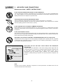
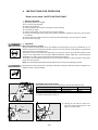
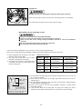
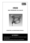
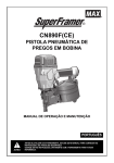
HN65
HIGH PRESSURE COIL NAILER
OPERATING and MAINTENANCE MANUAL
.
BEFORE USING THIS TOOL, STUDY THIS MANUAL TO ENSURE SAFETY WARNING
AND INSTRUCTIONS.
KEEP THESE INSTRUCTIONS WITH THE TOOL FOR FUTURE REFERENCE.
1
INDEX
ENGLISH
Page
3
to 15
Page
DEFINITIONS OF SIGNAL WORDS
WARNING:
Indicates a potentially hazardous situation which, if not avoided,
could result in death or serious injury.
CAUTION:
Indicates a potentially hazardous situation which, if not avoided,
may result in minor or moderate injury.
NOTE :
Emphasizes essential information.
2
ENGLISH
HN65
HIGH PRESSURE COIL NAILER
INDEX
1. SAFETY INSTRUCTIONS............................ 4
2. SPECIFICATIONS &
TECHNICAL DATA....................................... 7
3. AIR SUPPLY AND CONNECTIONS ............ 9
4. INSTRUCTIONS FOR OPERATION .......... 10
5. MAINTAIN FOR PERFORMANCE............. 15
6. STORING ................................................... 15
7. TROUBLESHOOTING/REPAIRS............... 15
OPERATING and MAINTENANCE MANUAL
BEFORE USING THIS TOOL, STUDY THIS MANUAL TO ENSURE SAFETY WARNING
AND INSTRUCTIONS.
KEEP THESE INSTRUCTIONS WITH THE TOOL FOR FUTURE REFERENCE.
3
1.
SAFETY INSTRUCTIONS
TO AVOID SEVERE PERSONAL INJURY OR PROPERTY DAMAGE
BEFORE USING THE TOOL, READ CAREFULLY AND UNDERSTAND THE FOLLOWING “SAFETY
INSTRUCTIONS”. FAILURE TO FOLLOW WARNINGS COULD RESULT IN DEATH OR SERIOUS INJURY.
PRECAUTIONS ON USING THE TOOL
1.
WEAR SAFETY GLASSES OR GOGGLES
Danger to the eyes always exists due to the possibility of dust being blown up by the exhausted air or of
a fastener flying up due to the improper handling of the tool. For these reasons, safety glasses or
goggles shall always be worn when operating the tool.
The employer and/or user must ensure that proper eye protection is worn. Eye protection equipment
must conform to the requirements of the American National Standards Institute, ANSI Z87.1 (Council
Directive 89/686/EEC of 21 DEC. 1989) and provide both frontal and side protection.
The employer is responsible to enforce the use of eye protection equipment by the tool operator and all
other personnel in the work area.
NOTE: Non-side shielded spectacles and face shields alone do not provide adequate protection.
2.
EAR PROTECTION MAY BE REQUIRED IN SOME ENVIRONMENTS
As the working condition may include exposure to high noise levels which can lead to hearing damage,
the employer and user should ensure that any necessary hearing protection is provided and used by the
operator and others in the work area.
3.
WHEN USING THE TOOL, BE SURE TO USE A SPECIAL AIR COMPRESSOR AND AIR HOSE
In order to improve its performance, it has set its working pressure higher than the conventional nailers.
To use the tool, you always need the special air compressor and air hose. Use of combusible pressure
gas (for example, oxygen, acetylene, etc.) causes abnormal combustion, possibly resulting in explosion.
Use only the special air compressor and air hose.
4.
OPERATE WITHIN THE PROPER AIR PRESSURE RANGE
The tool is designed to operate within an air pressure range of 170 to 320 p.s.i. (12 to 23 bar.)
The pressure should be adjusted to the type of the work being fastened. The tool shall never be operated
when the operating pressure exceeds 320 p.s.i. (23 bar.)
5.
DO NOT OPERATE THE TOOL NEAR A FLAMMABLE SUBSTANCE
Never operate the tool near a flammable substance (e.g., thinner, gasoline, etc.). Volatile fumes from
these substances could be drawn into the compressor and compressed together with the air and this
could result in an explosion.
6.
DO NOT USE A WRONG FITTINGS
The connector on the tool must not hold pressure when air supply is disconnected. If a wrong fitting is
used, the tool can remain charged with air after disconnecting and thus will be able to drive a fastener
even after the air line is disconnected, possibly causing injury.
7.
DISCONNECT THE AIR SUPPLY AND EMPTY THE MAGAZINE WHEN THE TOOL IS NOT IN USE
Always disconnect the air supply from the tool and empty the magazine when operation has been
completed or suspended, when unattended, moving to a different work area, adjusting, disassembling, or
repairing the tool, and when clearing a jammed fastener.
Gasoline
Thinner
4
8.
INSPECT SCREW TIGHTNESS
Loose or improperly installed screws or bolts cause accidents and tool damage when the tool is put into
operation. Inspect to confirm that all screws and bolts are tight and properly installed prior to operating
the tool.
9.
DO NOT TOUCH THE TRIGGER UNLESS YOU INTEND TO DRIVE A FASTENER
Whenever the air supply is connected to the tool, never touch the trigger unless you intend to drive a
fastener into the work. It is dangerous to walk around carrying the tool with the trigger pulled, and this
and similar actions should be avoided.
10.
NEVER POINT THE DISCHARGE OUTLET TOWARD YOURSELF AND OTHER PERSONNEL
If the discharge outlet is pointed toward people, serious accidents may be caused when misfiring. Be
sure the discharge outlet is not pointed toward people when connecting and disconnecting the hose,
loading and unloading the fasteners or similar operations.
11.
USE SPECIFIED FASTENERS (SEE PAGE 7)
The use of fasteners other than specified fasteners will cause the tool malfunction. Be sure to use only
specified fasteners when operating the tool.
12.
PLACE THE DISCHARGE OUTLET ON THE WORK SURFACE PROPERLY
Failure to place the discharge outlet of the nose in a proper manner can result in a fastener flying up and
is extremely dangerous.
13.
KEEP HANDS AND BODY AWAY FROM THE DISCHARGE OUTLET
When loading and using the tool, never place a hand or any part of body in fastener discharge area of the
tool. It is very dangerous to hit the hands or body by mistake.
14. DO NOT DRIVE FASTENERS CLOSE TO THE EDGE AND CORNER OF THE WORK AND THIN
MATERIAL
The workpiece is likely to split and the fastener could fly free and hit someone.
15.
DO NOT DRIVE FASTENERS ON TOP OF OTHER FASTENERS
Driving fasteners of the top of other fasteners may cause deflection fasteners which could cause injury.
16.
REMOVING THE FASTENERS AFTER COMPLETING OPERATION
If fasteners are left in the magazine after the completion of operation, there is the danger of a serious
accident occurring prior to the resumption of operation, should the tool be handled carelessly, or when
connecting the air fitting. For this reason, always remove all fasteners remaining in the magazine after
completion of the operation.
17. CHECK OPERATION OF THE CONTACT TRIP MECHANISM FREQUENTLY IN CASE OF USING A
CONTACT TRIP TYPE TOOL
Do not use the tool if the trip is not working correctly as accidental driving of a fastener may result. Do not
interfere with the proper operation of the contact trip mechanism.
5
18.
WHEN USING THE TOOL OUTSIDE OR ELEVATED PLACE
When fastening roofs or similar slanted surface, start fastening at the lower part and gradually work your
way up. Fastening backward is dangerous as you may loose your foot place.
Secure the hose at a point close to the area you are going to drive fasteners. Accidents may be caused
due to the hose being pulled inadvertently or getting caught.
19.
NEVER USE THE TOOL IF ANY PORTION OF THE TOOL CONTROLS (e.g., TRIGGER, CONTACT
ARM) IS INOPERABLE, DISCONNECTED, ALTERED OR NOT WOKING PROPERLY
20.
NEVER ACTUATE THE TOOL INTO FREE SPACE
This will avoid any hazard caused by free flying fasteners and excessive strain of the tool.
21.
ALWAYS ASSUME THAT THE TOOL CONTAINS FASTENERS
22.
RESPECT THE TOOL AS A WORKING IMPLEMENT
23.
NO HORSEPLAY
24.
NEVER LOAD THE TOOL WITH FASTENERS WHEN ANY ONE OF THE OPERATING CONTROLS
(e.g., TRIGGER, CONTACT ARM) IS ACTIVATED
OBSERVE THE FOLLOWING GENERAL CAUTION IN ADDITION TO
THE OTHER WARNINGS CONTAINED IN THIS MANUAL
・Do not use the tool as a hammer.
・Always carry the tool by the handle, never carry the tool by the air hose.
・The tool must be used only for the purpose it was designed.
・Never remove, tamper with the operating controls (e.g., TRIGGER, CONTACT ARM)
・Keep the tool in a dry place out of reach of children when not in use.
・Do not use the tool without Safety Warning label.
・Do not modify the tool from original design or function without approval by MAX CO., LTD.
6
2.
1.
SPECIFICATIONS AND TECHNICAL DATA
NAME OF PARTS
①
②
③
④
⑤
⑥
⑦
⑧
⑨
2.
TOOL SPECIFICATIONS
PRODUCT NO.
HEIGHT
WIDTH
LENGTH
WEIGHT
RECOMMENDED
OPERATING PRESSURE
LOADING CAPACITY
AIR CONSUMPTION
3.
Frame
Cylinder Cap
Contact Arm
Nose
Magazine
Trigger
Grip
Exhaust Cover
Trigger Lock Dial
HN65
11-7/8” (301 mm)
5” (129 mm)
10-5/8” (270 mm)
4.3 lbs. (1.9 kg)
170 to 320 p.s.i. (12 to 23 bar)
400 Nails
1.7 L at 257 p.s.i. (18 bar)
operating pressure
FASTENER SPECIFICATIONS
NAIL LENGTH
SHANK DIAMETER
SHANK TYPE
HEAD DIAMETER
WIRE WELDED
1-1/2” to 2-1/2” (38 to 65 mm)
.083” to .131” (φ2.1 to φ3.3 mm)
Smooth, Ring, Screw
CONTACT NOSE S
197” to .236” (φ5.0 to φ6.0 mm)
PLASTIC SHEET COLLATED
1-1/4” to 2-1/2” (32 to 65 mm)
.099” to .113” (φ2.5 to φ2.9 mm)
Smooth, Screw
CONTACT NOSE L
236” to .275” (φ6.0 to φ7.0 mm)
RECOMMENDED OPERATING PRESSURE:
170 to 320 p.s.i. (12 to 23 bar). Select the operating air pressure within this range for best fastener performance.
DO NOT EXCEED 320 p.s.i. (23 bar).
7
4.
TECHNICAL DATA
① NOISE
A-weighted single-event sound power level ------ LWA, 1s, d 93.8 dB
A-weighted single-event emission sound pressure level at work station ------ LpA, 1s, d 85.6 dB
These values are determined and documented in accordance to EN12549 : 1999.
② VIBRATION
Vibration characteristic value = 3.14 m/s2
These values are determined and documented in accordance to ISO 8662-11.
This value is a tool-related characteristic value and does not represent the influence to the hand-arm-system when using the tool.
An influence to the hand-arm-system when using the tool will for example depend on the gripping force, the contact pressure
force, the working direction, the adjustment of mains supply, the workpiece, the workpiece support.
5.
APPLICATIONS
*Floor and wall framing
*Subflooring
*Roof and wall sheathing
*Fencing
8
3.
AIR SUPPLY AND CONNECTIONS
Read section titled “ SAFETY INSTRUCTIONS ”.
DO NOT USE ANY POWER SOURCE EXCEPT AN AIR COMPRESSOR
The tool is designed to operate on compressed air. Do not operate the tool on any other combustible gases
(e.g., oxygen, acetylene, etc.) since there is the danger of an explosion. For this reason, absolutely do not use
anything other than an air compressor to operate the tool.
OPERATE WITHIN THE PROPER AIR PRESSURE RANGE
The tool is designed to operate within an air pressure range of 170 to 320 p.s.i. (12 to 23 bar.)
The pressure should be adjusted to the type of the work being fastened. The tool shall never be operated
when the operating pressure exceeds 320 p.s.i. (23 bar.)
Gasoline
Thinner
DO NOT OPERATE THE TOOL NEAR A FLAMMABLE SUBSTANCE
Never operate the tool near a flammable substance (e.g., thinner, gasoline, etc.). Volatile fumes from these
substances could be drawn into the compressor and compressed together with the air and this could result in
an explosion.
DO NOT USE A WRONG FITTINGS
The connector on the tool must not hold pressure when air supply is disconnected. If a wrong fitting is used,
the tool can remain charged with air after disconnecting and thus will be able to drive a fastener even after the
air line is disconnected, possibly causing injury.
DISCONNECT THE AIR SUPPLY AND EMPTY THE MAGAZINE WHEN THE TOOL IS NOT IN USE
Always disconnect the air supply from the tool and empty the magazine when operation has been completed
or suspended, when unattended, moving to a different work area, adjusting, disassembling, or repairing the
tool, and when clearing a jammed fastener.
[AIR COMPRESSOR / AIR HOSE]
Air compressor
Air hose
Used at 170 to 320 p.s.i. (12 to 23 bar)
WHEN USING THE TOOL, BE SURE TO USE A SPECIAL AIR COMPRESSOR
AND AIR HOSE.
In order to improve its performance, it has set its working pressure higher than the
conventional nailers. To use the tool, you always need the special air compressor and
air hose (MAX PowerLite Compressor and MAX PowerLite Hose). Use of
high-pressure gas (for example, oxygen, acetylene, etc.) causes abnormal
combustion, possibly resulting in explosion. Use only the special air compressor and
air hose.
NOTE:
Frequent, but not excessive, lubrication is required for the best performance. Oil added thru the air line
connection will lubricate the internal parts.
9
4.
INSTRUCTIONS FOR OPERATION
Read section titled “SAFETY INSTRUCTIONS”.
1.
①
②
③
④
⑤
⑥
⑦
BEFORE OPERATION
Wear Safety Glasses or Goggles.
Do not connect the air supply.
Inspect screw tightness.
Check operation of the contact arm & trigger if moving smoothly.
Connect the air supply.
Check the air-leakage. (The Tool must not have the air-leakage.)
Hold the Tool with finger-off the trigger, then push the contact arm against the work-piece. (The tool must
not operate.)
⑧ Hold the Tool with contact arm free from work-piece and pull the trigger. (The Tool must not operate.)
⑨ Disconnect the air supply.
2. OPERATION
Wear safety glasses or goggles
Danger to the eyes always exists due to the possibility of dust being blown up by the exhausted air or of a
fastener flying up due to the improper handling of the tool. For these reasons, safety glasses or goggles shall
always be worn when operating the tool.
The employer and/or user must ensure that proper eye protection is worn. Eye protection equipment must
conform to the requirements of the American National Standards Institute, ANSI Z87.1 (Council Directive
89/686/EEC of 21 DEC. 1989) and provide both frontal and side protection.
The employer is responsible to enforce the use of eye protection equipment by the tool operator and all other
personnel in the work area.
NOTE: Non-side shielded spectacles and face shields alone do not provide adequate protection.
Keep hands and body away from the discharge outlet when driving the fasteners because of dangerous of
hitting the hands or body by mistake.
ATTACHING THE CONTACT NOSE
Attatch the following contact noses depending on the nail head diameter used.
Head Diameter
Contact Nose
Color
.197” to 236” (φ5.0 to φ6.0 mm)
Contact Nose S
Black
.236” to 275” (φ6.0 to φ7.0 mm)
Contact Nose L
Silver
① Pull the contact nose to remove it.
② Aligning the rail with the contact arm,
press the contact nose as shown in the
figure to fit it until it clicks.
Contact Arm
Rail
10
Door Latch
NAIL LOADING
① Open the Magazine:
Pull up Door Latch and swing Door open. Swing Magazine Cover open.
② Check adjustment:
The Nail Support can be moved up and down to four settings. To change setting pull up
on the Nail Post and twist to the correct step. The Nail Support should be adjusted
correctly to the position indicated in inches and millimeters inside Magazine.
Magazine
Nail Support
③ Nail loading:
Place a coil of nails over the Nail Post in the Magazine. Uncoil enough nails to reach
the Feed Pawl, and place the second nail between the teeth on the Feed Pawl. The
nail heads fit in slot on Nose.
Slot
Feed Pawl
Nail
④ Swing Magazine Cover closed.
⑤ Close the Door.
Check that Door Latch engages. (If it does not engage, check that the nail heads are in
the slot on the Nose).
11
TEST OPERATION
① Adjust the air pressure at 170 p.s.i. (12 bar) and connect the air supply.
② Without touching the Trigger, depress the Contact Arm against the work-piece.
Pull the Trigger. (The tool must fire the fastener.)
③ With the tool off the work-piece, pull the Trigger.
Then depress the Contact Arm against the work-piece.
(The tool must fire the fastener.)
④ Adjust the air pressure as much as the lowest possible according to the diameters and length of fastener
and the hardness of work-piece.
MODEL IDENTIFICATION
CONTACT TRIP
The common operating procedure on “Contact Trip” tools is for the operator to contact the work to actuate the
trip mechanism while keeping the Trigger pulled, thus driving a fastener each time the work is contacted. This
will allow rapid fastener placement on many jobs, such as sheathing, decking and pallet assembly.
All pneumatic tools are subject to recoil when driving fasteners. The tool may bounce, releasing the trip, and if
unintentionally allowed to recontact the work surface with the Trigger still actuated (finger still holding Trigger
pulled) an unwanted second fastener will be driven.
CONTACT TRIP WITH ANTI-DOUBLE FIRE MECHANISM
(US patent 5597106, UK patent 2286790)
Identified by RED TRIGGER.
SEQUENTIAL TRIP
The Sequential Trip requires the operator to hold the tool against the work before pulling the Trigger. This
makes accurate fastener placement easier, for instance on framing, toe nailing and crating applications. The
Sequential Trip allows exact fastener location without the possibility of driving a second fastener on recoil, as
described under “Contact Trip”.
The Sequential Trip Tool has a positive safety advantage because it will not accidentally drive a fastener if the
tool is contacted against the work-or anything else-while the operator is holding the trigger pulled.
SEQUENTIAL TRIP
Identified by ORANGE TRIGGER.
12
CONTACT FIRE OPERATION (CONTACT TRIP)
For contact fire operation, hold the Trigger and depress the Contact Arm against the work surface.
PROCEDURE
① Hold the Trigger.
② Depress the Contact Arm.
SINGLE FIRE OPERATION (ANTI-DOUBLE FIRE MECHANISM AND SEQUENTIAL TRIP)
For single fire operation, depress the Contact Arm against the work surface and pull the Trigger. Tool can not
fire a second nail until the Trigger is released and tool can cycle.
PROCEDURE
① Depress the Contact Arm.
② Pull the Trigger.
DRIVING DEPTH ADJUSTMENT DIAL
Adjustment Dial
Deeper
Adjust Spacer
ALWAYS disconnect air supply before adjustment dial.
① With air pressure set, drive nails into a representative material sample to determine if
adjustment is necessary.
Shallow
② If adjustment is required, disconnect air supply.
③ Refer to the mark on the Adjust Spacer for direction to turn the adjustment dial.
④ Reconnect air supply.
Deeper
Shallow
TRIGGER LOCK MECHANISM
The tool is equipped with a Trigger Lock Mechanism. Push and rotate Trigger Lock Dial
from the LOCK to the UNLOCK position before driving nails.
Trigger Lock Dial
Trigger
13
CONTACT TIP
ALWAYS disconnect air supply before attaching / detaching the contact tip.
Attach the Contact Tip on the tip of Contact Arm, when driving nails to a soft material.
Arm Cover
Contact Arm
Contact Tip
The Contact Tip can be kept on the Arm Cover when not using.
WHEN USING THE TOOL FOR STEEL PLATES
● Carry out work based on the required Work Standards.
● If there is no specified work standard, refer the following as a reference.
● Never use the nails for the ceilings (ceiling foundations included) or roofs (roof foundations
included).
● Be sure to apply discharge outlet to an object at a right angle.
● Do not drive the nails into the steel plate directly.
This tool is exclusively designed for 1/16” (1.6 mm) to 1/8” (3.2 mm) thick light gage steel.
When using it, comply with the Work Standards, considering the object condition and work site environment.
① Select appropriate nails according to the object
thickness, seeing the right table.
※ The nails may not be driven into the object
depending on its hardness or thickness.
※ If the object is thinner than an appropriate range
of thickness, the nails may not be driven into it
because of being bent.
Wood
Object thickness
(Total) range
Penetration
amount
Light gage steel:
1/16” (1.6 mm) to
1/8” (3.2 mm) thick
Nail Selection Criteria
Object thickness
(Total) range
1” to 1-3/8”
(25 to 35mm)
Light gage
steel thickness
16 Gage to 13 Gage
(1.6 to 2.3mm)
1” to 1-1/2”
(25 to 40mm)
16 Gage to 13 Gage
(1.6 to 2.3mm)
2-1/4”
(57mm)
1-3/8” to 1-3/4”
(35 to 45mm)
16 Gage to 13 Gage
(1.6 to 2.3mm)
2-3/8”
(60mm)
1-1/2” to1-1/8”
(40 to 55mm)
16 Gage to 13 Gage
(1.6 to 2.3mm)
Diamete
Length
.099”
(2.5mm)
.099”
(2.5mm)
1-3/4”
(45mm)
2”
(50mm)
.099”
(2.5mm)
.099”
(2.5mm)
② If the thickness of the light gage steel foundations material used is 1/8” (3.2 mm), use
the .113” (φ2.9 mm) nails.
③ Never drive the nails directly into the light gage steel because they will fly off,
endangering you.
④ Be sure to apply the discharge outlet to the object at a right angle. If applied obliquely,
the nails will fly off, endangering you.
⑤ Never use the nails for the roofs (roof foundations included) or ceilings (ceiling
foundations included).
⑥ If the nails are driven into the steel plate too deeply, their holding force will be
extremely reduced. When working with the tool, fully check the driven conditions.
※ For the 1/8” (3.2 mm) thick light gage
steel, use the .113” (φ2.9 mm) nails.
14
5.
MAINTAIN FOR PERFORMANCE
① DO NOT FIRE THE NAILER WHEN IT IS EMPTY
② USE RECOMMENDED OIL
The velocite or turbine oil should be used to lubricate the tool. Upon completion of operations, place 2 or 3
drops of oil into the air plug inlet with the jet oiler. (Recommended Oil : ISO VG32)
③ INSPECT AND MAINTAIN DAILY OR BEFORE OPERATION
Disconnect air supply and empty the magazine when inspecting or maintaining the tool.
(1) Drain air line filter and compressor
(2) Keep lubricator filled in air 3-pieces set
(3) Clean filter element of air 3-pieces set
(4) Tighten all screws
(5) Keep contact arm moving smoothly
6.
①
②
③
④
7.
STORING
When not in use for an extended period, apply a thin coat of the lubricant to the steel parts to avoid rust.
Do not store the tool in a cold weather environment. Keep the tool in a warm area.
When not in use, the tool should be stored in a warm and dry place. Keep out of reach of children.
All quality tools will eventually require servicing or replacement of parts because of wear from the normal
use.
TROUBLE SHOOTING/REPAIRS
The troubleshooting and/or repairs shall be carried out only by the MAX CO., LTD.authorised distributors
or by other specialists.
15
16
・ The content of this manual might be changed without notice for improvement.
NIHONBASHI-HAKOZAKI-CHO, CHUO-KU, TOKYO, JAPAN
[ 6-6
]
Tel: (03) 3669-8131 Telefax: (03) 3669-7104
http://www.maxusacorp.com (USA Site)
http://www.max-ltd.co.jp/int/ (GLOBAL Site)
★060117-00/01
PRINTED IN JAPAN
17
SuppIément au mode d’emploi
Selon Ia norme européenne EN 792-13 le
réglement suivant est valable du 1.1.2001, que
toutes machines à enfoncer les fixations
équipées de commande par contact doivent être
marquées avec le symbole ,,Ne pas utiliser sur
des échafaudages ou e’chelles,, et elles ne
seront pas utilisées pour utilisations spécifiques,
par example:
- en cours de déplacement d’ un lieu d’
enfoncement à l’autre sur des échafaudages,
escaliers, échelles ou constructions de même
qu ‘ êchelles comme p.e. lattis du toit
- pour fermer des boîtes ou des caisses
- pour fixer des systèmes d’arrimages p.e. sur
véhicules ou wagons.
Supplement to the operating instruction
According to the European Norm EN 792-13 the
regulation is valid from 01.01.2001 that all
fastener driving tools with contact actuation must
be marked with the symbol “Do not use on
scaffoldings, ladders” and they shall not be used
for specific application for example:
- when changing one driving location to another
involves the use of scaffoldings, stairs, ladders
or ladder alike constructions e.g. roof laths,
- closing boxes or crates,
- fitting transportation safety systems e.g. on
vehicles and wagons.
Ergänzung zur Betriebsanleitung von
MAX-Naglern
Unter der am O1 Januar 2001 in Kraft tretenden
europäischen Norm EN 792-13 müssen
Eintreibgeräte mit Kontaktauslüsung mit dem
Symbol
? Nicht von Gerüsten oder Leitern benutzen
“ gekennzeichnet sein und dürfen nicht für
bestimmte Anwendungen benutzt werden? zum
Beispiel.
- wenn das Wechseln von einer Eintreibstelle zur
anderen über Gerüste, Treppen, Leitern oder
leiterähnliche Konstruktionen, wie z.B.
Dachlattungen, erfolgt,
- das Schließen von Kisten oder Verschlägen,
- beim Anbringen von Transportsicherungen z.B.
auf Fahrzeugen und Waggons.
Supplemento relativo alle istruzioni
di servizio
Secondo Ia norma europea EN 792-13, il
regolamento vale del 1. 1.2001 che tutti
apparecchi per chiodatura muniti di scatto a
contatto devono essere contrassegnati con il
simbolo ,,Non utilizzare da impalcature o scale a
pioli” e non devono essere utilizzati per utilizzi
certi, per esempio:
- se il passaggio da un punto di chiodatura ad un
altro avviene passando da impalcature, scale,
scale a pioli o construzioni simili come p.e. i
graticiatti del tetto,
- nella chiusura di casse o gabbie
- nell’ applicazione de assicurazioni per il
trasporto, p.e. su veicoli e vagoni.
Suplemento a la instrucción para la
operación
Según la Norma Europea EN792-13, la
regulación es válida desde el 1˚ de enero de
2001, que todas las herramientas para clavado
de sujetadores, con actuación de contacto, se
deben marcar con el símbolo “No utilice en
andamios y escalas”, y no deben ser utilizados
para un uso específico, por ejemplo:
- cuando el cambio de una posición de clavado a
otra implica el uso de andamios, escaleras,
escalas, o construcciones semejantes a
escala, e.g. listones de techo,
- cierre de cajas o cajones,
- instalación de sistemas de seguridad de
transporte e.g. en los vehículos y carros.