1
fi-4340C Image Scanner
Operator's Guide
Revisions, Disclaimers
Edition
Date published
Revised contents
01
October, 2001
First edition
02
March, 2003
Second edition
03
August, 2003
Third edition
04
October, 2004
Fourth edition
06
June, 2006
Sixth edition
Specification No. P3PC-E832-06EN
NOTICE
This manual is for fi-4340C equipped with both USB and SCSI interfaces.
Explanations related to the USB interface do not apply to fi-4340C equipped only
with SCSI interface.
Regulatory Information
■
FCC declaration
This equipment has been tested and found to comply with the limits for a Class B
digital device, pursuant to Part 15 of the FCC Rules. These limits are designed to
provide reasonable protection against harmful interference in a residential
installation. This equipment generates, uses, and can radiate radio frequency
energy and, if not installed and used in accordance with the instruction manual, may
cause harmful interference to radio communications. However, there is no
guarantee that interference will not occur in a particular installation. If this
equipment does cause harmful interference to radio or television reception, which
can be determined by turning the equipment off and on, the user is encouraged to
try to correct the interference by one or more of the following measures:
• Reorient or relocate the receiving antenna.
• Increase the separation between the equipment and receiver.
• Connect the equipment into an outlet on a circuit different from that to which
the receiver is connected.
• Consult the dealer or an experienced radio/TV technician for help.
FCC warning: Changes or modifications not expressly approved by the party
responsible for compliance could void the user’s authority to operate the equipment.
NOTICE
• The use of a non-shielded interface cable with the referenced device is
prohibited. The length of the parallel interface cable must be 3 meters (10 feet)
or less. The length of the serial interface cable must be 15 meters (50 feet) or
less.
• The length of the power cord must be 3 meters (10 feet) or less.
i
■
Canadian DOC Regulations
This digital apparatus does not exceed the Class B limit for radio noise emissions
from digital apparatus set out in the Radio interference Regulations of the Canadian
Department of Communications.
This Class B digital apparatus complies with Canadian ICES-003.
Le présent appareil numérique pas de bruits radioélectriques dépassant les limites
applicables aux appareils numériques de la classe B prescridtes dans le
Réglesment sur le brouillage radioélectrique dicté par le ministere des
Communications du Canada.
Cet appareil numérique de la classe B est conformme à la norme NMB-003 du
Canada.
■
Bescheimigung des Herstellers / Importeurs
Für den fi-4340C wird folgendes bescheinigt:
• In Übereinsstimmung mit den Bestimmungen der EN45014(CE) funkentstört
• Maschinenlärminformationsverordnung 3.GPSGV: Der höchste
Schalldruckpegel beträgt 70 dB (A) oder weniger, gemäß EN ISO 7779.
■
International ENERGY STAR® Program
As an ENERGY STAR® Partner, PFU LIMITED has
determined that this product meets the ENERGY STAR®
guidelines for energy efficiency.
The International ENERGY STAR® Office Equipment
Program is an international program that promotes energy
saving through the penetration of energy efficient
computers and other office equipment. The program backs
the development and dissemination of products with
functions that effectively reduce energy consumption. It is
an open system in which business proprietors can
participate voluntarily. The targeted products are office equipment such as
computers, monitors, printers, facsimiles, copiers, scanners, and multifunction
devices. Their standards and logos are uniform among participating nations.
ii
■
Use in High-safety Applications
This product has been designed and manufactured on the assumption that it will be
used in office, personal, domestic, regular industrial, and general-purpose
applications. It has not been designed and manufactured for use in applications
(simply called "high-safety applications" from here on) that directly involve danger to
life and health when a high degree of safety is required, for example, in the control
of nuclear reactions at nuclear power facilities, automatic flight control of aircraft, air
traffic control, operation control in mass-transport systems, medical equipment for
sustaining life, and missile firing control in weapons systems, and when
provisionally the safety in question is not ensured. The user shall use this product
with adopting measures for ensuring safety in such high-safety applications. PFU
LIMITED assumes no liability whatsoever for damages arising from use of this
product by the user in high-safety applications, and for any claims or compensation
for damages by the user or a third party.
■
About the use of mercury
Hg
Lamp(s) inside this product contain mercury and must
be recycled or disposed of according to local, state, or
federal laws.
To avoid unexpected injury, read the following carefully.
Doing the following actions may result in serious personal injuries:
• Do not put the substance contained in the lamp in your mouth as it has
mercury
• Do not incinerate, crush, or shred the lamps or scanner parts.
• Do not breathe the chemical liquid contained in the scanner lamps.
■
Copying
Copying of paper money, coins, securities and passports issued by government
authorities, licenses and permits issued by public authorities and private
organizations, official documents, and private documents etc. is illegal and is
subject to punishment.
■
Copyright
Copyright had items such as books, paintings, prints, maps, drawings, and
photographs may be copied only for private or home use, or for similar applications.
Copying for other applications without the consent of the holder of the copyright is
illegal.
iii
■
Trademarks
Microsoft, Windows, and Windows NT are registered trademarks of the Microsoft
Corporation in the United States and/or other countries.
ISIS and QuickScan are trademarks or registered trademarks of EMC Corporation in
the United States.
Adobe, the Adobe logo, and Acrobat are either registered trademarks of Adobe
Systems Incorporated in the United States and/or other countries.
Other product names are the trademarks or registered trademarks of the respective
companies.
■
How Trademarks Are Indicated In This Manual
References to Operating systems (OS) are indicated as follows:
Windows 95
Microsoft® Windows® 95 operating system
Windows 98
Microsoft® Windows® 98 operating system
Windows Me
Microsoft® Windows® Millennium Edition
operating system
WindowsNT 4.0
Microsoft® Windows NT® 4.0 Server operating system,
Microsoft® Windows NT® 4.0 Workstation
operating system
Windows 2000
Microsoft® Windows® 2000 Professional
operating system
Windows XP
Microsoft® Windows® XP Professional operating
system,
Microsoft® Windows® XP Home Edition operating
system
Where there is no distinction between the different versions of the above operating
system, the general term “Windos “ is used.
■
Manufacturer
PFU LIMITED
Image Products Sales Dept., Imaging Products Division, Products Group
Solid Square East Tower, 580 Horikawa-cho, Saiwai-ku, Kawasaki-shi Kanagawa
212-88563, Japan
Phone : (81-44) 540-4538
All Rights Reserved, Copyright © PFU LIMITED 2006
The contentss of this manual may be revised without prior notice.
No part of this manual may be reproduced in any form without permission.
iv
Fujitsu Group Offices
Please send your comments on this manual or on Fujitsu products to the following
addresses:
FUJITSU COMPUTER PRODUCTS
OF AMERICA, INC.
FUJITSU CANADA, INC.
1255 East Arques Avenue Sunnyvale,
CA 94085-4701, U.S.A.
Phone: (1-408)746-7000
Technical Assistance Center:
(1-800)626-4686
Fax: (1-408)746-6910
Website: http://www.fcpa.fujitsu.com/
E-mail: info@fcpa.fujitsu.com
6975 Creditview Road Unit 1
Mississauga, On L5N 8E9 Canada
Phone: (1-905)286-9666
Fax: (1-905)286-5988
Website: http://www.fujitsu.ca/
E-mail: imaging@fujitsu.ca
(For Sales Questions)
scantech@fujitsu.ca
(For technical questions)
FUJITSU EUROPE LTD.
FUJITSU DEUTSCHLAND GmbH.
Hayes Park Central, Hayes End Road,
Hayes Middlesex UB4 8FE, U.K.
Phone: (44-208)573-4444
Fax: (44-208)573-2643
Website: http://www.fel.fujitsu.com/
Frankfurter Ring 211, 80807 München,
Germany
Phone: (49-89)323-78-0
Fax: (49-89)323-78-100
Website: http://www.fdg.fujitsu.com/
E-mail:
hotline_scanner@fdg.fujitsu.com
FUJITSU ITALIA S.p.A.
FUJITSU ESPAÑA Services, S.A.U.
Via Nazario Sauro, 38
20099 Sesto San Giovanni (MI), Italy
Phone: (39-02)26294.1
Fax: (39-02)26294.201
Website: http://www.fis.fujitsu.com/
E-mail: mbarondi@fis.fujitsu.com
Camino Cerro de los Gamos, 1 28224,
Pozuelo de Alarcon, Madrid, Spain
Phone: (34-91)784-9000
Fax: (34-91)784-9379
Website: http://es.fujitsu.com/
E-mail: info@mail.fujitsu.es
FUJITSU AUSTRALIA LTD.
FUJITSU ASIA PTE.LTD.
Fujitsu House 2 Julius Avenue
North Ryde, N.S.W 2113 Australia
Phone: (61-2)9776-4555
Fax: (61-2)9776-4024
Website: http://au.fujitsu.com/
20 Science Park Road, #03-01, Tele Teck
Park Singapore Science Park II, Singapore 117674
Phone: general (65)6512-7555
query (65)6512-7431
Fax: (65)6512-7499
Website: http://www.fapl.fujitsu.com
E-mail: query@sg.fujitsu.com
FUJITSU TAIWAN LTD.
FUJITSU HONG KONG LTD.
19th Fl., No39, Sec.1,Chung-hwa Rd.,
Taipei, Taiwan
Phone: (886-2)2311-2255
Fax: (886-2)2311-2277
Website: http://tw.fujitsu.com/
10/F., Lincoln House, 979 King's Road,
Taikoo Place, Island East, Hong Kong
Phone: (852)2827-5780
Fax: (852)2827-4724
Website: http://hk.fujitsu.com/
E-mail: scanner@fujitsu.com.hk
v
FUJITSU SYSTEMS BUSINESS
(THAILAND) LTD.
vi
FUJITSU KOREA LTD.
12th Fl., Olympia Thai Tower, 444
Rachadapisek Road, Samsennok,
Huay kwang, Bangkok 10310, Thailand
Phone: +66 (0) 2500-1500
Fax: +66 (0) 2500-1555
Website: http://th.fujitsu.com/
Susong Tower Building, 83-1
Susong-Dong, Jongno-Gu, Seoul,
Republlic of Korea
Phone: (82-2)3787-6159
Fax: (82-2)3787-6164
Website: http://kr.fujitsu.com/
E-mail: webmaster@kr.fujitsu.com
FUJITSU MALAYSIA SDN.BHD.
FUJITSU PHILIPPINES, INC
Level 1 & 2
3505 Jalan Teknokrat 5
63000 Cyberjaya
MALAYSIA
Phone:
general (603)8318-3700
query (603)8318-3700 (ext 375)
Fax: (603)8318-8700
Website: http://www.fujitsu.com/my/
E-mail: WriteToUs@fms.my.fujitsu.com
2/F, United Life Building, 837 A. Arnaiz
Avenue (Pasay Road),
Legaspi Village, Makati City 1229,
Philippines
Phone: +63 (2) 812-4001
Fax: +63 (2) 817-7576
Website: http://ph.fujitsu.com
Imaging Business Division,
PFU LIMITED
PFU LIMITED
(Corporate headquarters)
Solid Square East Tower, 580
Horikawa-cho, Saiwai-ku, Kawasaki-shi,
Kanagawa 212-8563, Japan
Phone: (81-44)540-4658
Fax: (81-44)540-4639
Website:
http://imagescanner.fujitsu.com
E-mail: scanners@pfu.fujitsu.com
Nu 98-2 Unoke, Kahoku-shi,
Ishikawa 929-1192, Japan
Phone: (81-76)283-1212
Fax: (81-76)283-4689
Note, Liability
READ ALL OF THIS MANUAL CAREFULLY BEFORE USING THIS PRODUCT. IF
THIS PRODUCT IS NOT USED CORRECTLY, UNEXPECTED INJURY MAY BE
CAUSED TO USERS OR BYSTANDERS.
Also, store this manual in a safe place so that it can be easily referred to during use
of this product.
While all efforts have been made to ensure the accuracy of all information in this
manual, PFU assumes no liability to any party for any damage caused by errors or
omissions or by statements of any kind in this manual, its updates or supplements,
whether such errors are omissions or statements resulting from negligence,
accidents, or any other cause. PFU further assumes no liability arising from the
application or use of any product or system described herein; nor any liability for
incidental or consequential damages arising from the use of this manual. PFU
disclaims all warranties regarding the information contained herein, whether
expressed, implied, or statutory.
vii
Preface
This manual explains how to use the fi-4340C image scanner.
This manual contains chapters on the following topics:
COMPONENTS
INSTALLATION AND CONNECTIONS
HOW TO INSTALL THE DEVICE DRIVER
OPERATING INSTRUCTIONS
ADF DOCUMENT SPECIFICATION
OPERATOR PANEL MESSAGE
SETUP MODE
TROUBLESHOOTING
CONSUMABLES AND OPTIONS
SCANNER SPECIFICATIONS
It also contains a Glossary of Terms and an Index.
Refer to the Cleaning and Maintenance Guide for information about the routine
operation of the fi-4340C.
The Cleaning and Maintenance Guide contains chapters on OPERATING
INSTRUCTIONS, CLEANING, REPLACEMENT OF PARTS, ADJUSTMENT and
TROUBLESHOOTING.
The fi-4340C is a very fast and highly functional color image scanner developed for
high quality color image processing, using charge-coupled device (CCD) color
image sensors. This scanner features high-speed duplex scanning with an automatic document feeder (ADF).
viii
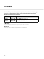
Conventions
Important information that requires special attention is indicated as follows:
WARNING
WARNING indicates that serious personal injury may result if you do not follow a
procedure correctly.
CAUTION
CAUTION indicates that minor personal injury, loss of data, or damage to the
scanner may result if you do not follow a procedure correctly.
NOTICE
A NOTICE provides “how-to” tips or suggestions to help you perform a procedure
correctly.
A TRIANGLE symbol indicates that special care and attention is
required.
The drawing inside the triangle shows the specific caution.
A CIRCLE with a diagonal line inside shows action which users
may not perform.
The drawing inside or under the circle shows the specific action
that is not allowed.
R
■
Outline characters on a colored background show instructions
users should follow.
It may also include the drawing that shows the specific instruction.
Warning Label
The glass surface inside the ADF becomes hot during the operation. Be careful not to touch the glass surface inside the ADF.
CAUTION
Do NOT remove from the scanner, stain or scratch the warning labels.
■
About Maintenance
The user must not perform repairs on this scanner.
Contact the store where you purchased the scnner or an authorized FUJITSU
Image Sanner service provider to make repairs to this product.
ix
Precautions
This section describes precautions to follow when installing the scanner.
To ensure the longevity and proper functioning of your scanner, do not install the
scanner in the places and environments described below.
■
Warning
Important warnings employed in this manual are as follows.
Do not damage the power cable.
Damage to the power cable may result in fire or electric shock. Do
not place heavy objects on power cables, or pull, bend, twist, heat,
damage orr modify power cables. Also do not use damaged power
calbes or power plugs, or when the wall socket is loose.
Use only the specified power cable or extension cable.
Use only the specified power cable or connector cables. Failure to
use the correct cables might cause electric shock and equipment
failure.
Use this scanner only at the indicated power voltage. Do not
connect to multiple-power strips.
Use this scanner only at the indicated power voltage and current.
Impropoer power voltage and current might cause fire or electric
shock. Also, do not connect to multiple-power strips.
Wipe any dust from the power plug.
Wipe off any dust from metal parts on the power plug or metal fitting
with a soft, dry cloth. Accumulated dust might cause fire or electric
shock.
x
Do not install the device in locations subject to oil smoke, steam,
humidity, and dust.
Do not install the scanner in locations subject to oil smoke, steam,
humidity, and dust. Doing so might cause a fire or electric shock.
Installation in areas with high levels of oil smoke, steam, humidity,
or dust may result in fire or electric shock.
Do not use the scanner if you smell a strange odor.
If you detect heat coming from the device or detect other problems
such as smoke, strange smells or noises, immediately turn off the
scanner and then disconnect its power plug. Make sure that the
smoking has stopped, and then contact the store where you bought
the scanner or an authorized FUJITSU scanner service provider.
Ensure that water or foreign matter does not enter the
equipment.
Do not insert or drop metal objects into the scanner. Do not scan
wet documents or documents with paper clips or staples. Do not
splash or allow the scanner to get wet.
If foreign objects (water, small metal objects, liquids, etc.) get inside
the scanner, immediately turn off the scanner and disconnect the
power plug from the power outlet, then contact the store where you
purchased the scanner or the Maintenance Service Center. Pay
particular attention to this warning in households where there are
small children.
Do not touch the inside of the scanner unless necessary.
Do not take apart or modify the scanner. The inside of the scanner
contains high-voltage components. Touching these components
might cause fire or electric shock.
xi
Before moving the scanner, disconnect the power plug from the
power outlet.
Do not move the scanner with the power and interface cables
connected as this might damage the cables, causeing fire, electric
shock or injuries. Before moving the scanner, be sure to disconnect
the power plug from the power outlet, and disconnect data cables.
Also, make sure that the floor is free of obstructions.
Switch power OFF if the equipment is damaged.
If the equipment is dropped, or covers etc. have been damaged,
switch power supply OFF, remove the plug from the socket, and call
your dealer or maintenance service center.
Do not place in wet areas.
Do not place the scanner where liquid spills may occur.
■
Caution
Important cautions employed in this manual are as follows.
Do not touch the power cable with wet hands.
Do not touch the power plug with wet hands. Doing so might cause
electric shock.
Earth the equipment.
This equipment must be earthed. Always connect the power cable
to a 3-pin socket. If earthing is not possible, call your dealer or
maintenance service center.
xii
Do not install the scanner on unstable sufaces.
Install the scanner on a desk so that none of its parts protrude
outside of the desktop. Also, make sure that the scanner is installed
on a flat, level surface. Do not install the scanner on unstable
surfaces. Install the scanner on a level surface that is free of
vibration to prevent it from falling.
Install the scanner on a strong surface that will support the weight
of the scanner and other devices.
Firmly insert the power plug.
Firmly insert the power plug into the power outlet as far it can go.
Do not block the ventilation ports.
Do not block the ventilation ports. Blocking the ventilation ports
generates heat inside of the scanner, which may results in fire or
scanner failure.
Do not place heavy objects or climb on top of the scanner.
Do not place heavy objects on the scanner or use the scanner’s top
surface for performing other work. Improper installation might cause
injuries.
Before moving the scanner, disconnect the power plug from the
power outlet.
Do not move the scanner with the power and interface cables
connected as this might damage the cables, causing fire, electric
shock or injuries. Before moving the scanner, be sure to disconnect
the power plug from the power outlet, and disconnect data cables.
Also, make sure that the floor is free of obstructions.
xiii
Protect the scanner from static electricity.
Install the scanner away from strong magnetic fields and other
sources ofr electronic noise. Also, protect the scanner from static
electricity as this might cause the scanner to malfunction.
Be careful not to get neckties, necklaces, hair, etc. entangled in
the scanner.
You may get injured if your clothing, neckties, or hair, etc. is
entangled in the moving components such as gears and rollers.
Disconnect the power plug from the power outlet when the
scanner is not used for a long period of time.
When the scanner is not used for a long period of time, be sure to
disconnect the power plug from the power outlet for safety.
Do not install the scannner in direct sunlight.
Do not install the scanner in the direct sunlight or near heating
apparatus. Doing so might cause excessive heat to build up inside
the scanner, causing fire or scanner trouble. Install the scanner in a
well-ventilated location.
xiv
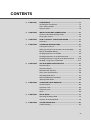
CONTENTS
❏
CHAPTER 1
COMPONENTS ..................................................................1-1
Checking the Components ..................................................1-2
Units and Assemblies ..........................................................1-3
Operator Panel ....................................................................1-6
❏
CHAPTER 2
INSTALLATION AND CONNECTIONS .............................2-1
Confirm of the Manufacturing Labels ..................................2-2
Placing the scanner .............................................................2-3
❏
CHAPTER 3
HOW TO INSTALL THE DEVICE DRIVER ........................3-1
Procedure ............................................................................3-2
❏
CHAPTER 4
OPERATING INSTRUCTIONS ...........................................4-1
Turning the Power On .........................................................4-2
Waking up the Scanner from the Low Power Mode ............4-3
Manual Feed Mode Setting .................................................4-4
Loading Documents on the ADF .........................................4-5
Loading Documents on the Document bed .........................4-9
Loading Documents Larger than the Document bed ........4-10
Reading a Page from a Thick Book ..................................4-11
❏
CHAPTER 5
ADF DOCUMENT SPECIFICATION ..................................5-1
Document Size ....................................................................5-2
Document Quality ................................................................5-3
Maximum ADF Capacity .....................................................5-5
Areas not to be Perforated ..................................................5-6
Grounding Color Areas .......................................................5-7
Multi Feed Detection Conditions .........................................5-8
Job Separation Sheet ..........................................................5-9
❏
CHAPTER 6
OPERATOR PANEL MESSAGE ........................................6-1
Counter Display ...................................................................6-2
Operation status ..................................................................6-3
Temporary error ..................................................................6-4
Alarm ...................................................................................6-5
❏
CHAPTER 7
SETUP MODE ....................................................................7-1
Activating the Setup Mode ..................................................7-2
Contents of the Setup Mode ...............................................7-3
❏
CHAPTER 8
TROUBLESHOOTING ........................................................8-1
Troubleshooting ..................................................................8-2
xv
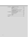
❏
CHAPTER 9
CONSUMABLES AND OPTIONS ......................................9-1
Consumables ......................................................................9-2
Options ................................................................................9-3
VIDEO INTERFACE BOARD ..............................................9-4
IPC-4D(IMAGE PROCESSING CIRCUIT BOARD) ............9-9
fi-434PR(IMPRINTER) ......................................................9-10
fi-475CMP3(JPEG COMPRESSION BOARD) ..................9-11
❏
CHAPTER 10
SCANNER SPECIFICATIONS .........................................10-1
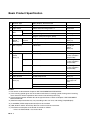
Basic Product Specification ...............................................10-2
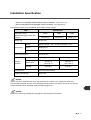
Installation Specification ....................................................10-3
Dimensions .......................................................................10-4
xvi
❏
GLOSSARY OF TERMS ...........................................................................GL-1
❏
INDEX ......................................................................................................... IN-1
1
COMPONENTS
CHAPTER 1
2
INSTALLATION AND CONNECTIONS
CHAPTER 2
3
HOW TO INSTALL THE DEVICE DRIVER
CHAPTER 3
4
OPERATING INSTRUCTIONS
CHAPTER 4
5
ADF DOCUMENT SPECIFICATION
CHAPTER 5
6
OPERATOR PANEL MESSAGE
CHAPTER 6
7
SETUP MODE
CHAPTER 7
8
TROUBLESHOOTING
CHAPTER 8
9
CONSUMABLES AND OPTIONS
CHAPTER 9
10
SCANNER SPECIFICATIONS
CHAPTER10
GLOSSARY OF TERMS
INDEX
GLOSSARY
INDEX
CHAPTER
1
COMPONENTS
This chapter describes checking the Components, Units and Assemblies of
the scanner, and operator panel arrangement,and the function of parts.
Checking the Components ........................................................1-2
Units and Assemblies ................................................................1-3
Operator Panel............................................................................1-6
●1-1
Checking the Components
These high precision components must be handled carefully.
Confirm that all the components shown in the following figure have been received.
If any component is missing, please contact your sales agent.
Scanner
Power cable (*1)
Power cable (*2)
Operator’s Guide(this
manual) and
Device driver(CD) and
User Manual(CD)
Pad ASSY (*3)
USB cable
*1) for North America
*2) for Europe
*3) Pad ASSY is attached
to the back of the ADF
Paper chute.
NOTICE
The CD-ROMs contains “Cleaning and Maintenance” and this manual.
●1-2
Units and Assemblies
This section shows the exterior view and assemblies of the scanner. This section also provides the name
of each part and describes its functions.
■
Units
(1)Document cover
(3)Document holding pad
(4)Automatic document
feeder(ADF)
(2)Document bed
(5)Stacker
(6)Operator panel
(7)Shipping lock
(8)ADF paper chute
(9)ADF lever
(16)Third party slot
(Option board Slot)
(17)Spare Pad ASSY
(15)SCSI Interface connector
(10)Power switch
(12)EXT connector
(11)Power Inlet
(18)Side guide
(14)SCSI ID switch
(13)SCSI terminator switch
(19)USB Interface connector
NOTICE
The Shipping lock should be switched to the operating position when the scanner is to be used. Refer to
Chapter2 "Placing the Shipping lock (page 2-3)" for details.
●1-3
No .
Part
Function
1
Document cover
Closes over and keeps in place the document to be read.
2
Document bed
Holds document to be read. Also called Flatbed (FB).
3
Document holding pad
Presses document to the Document bed.
4
Automatic document feeder
(ADF)
Automatically feeds documents to the reading position.
5
Stacker
Stacks the read documents.
6
Operator panel
Contains indicator panel that indicates scanner status.
7
Shipping lock
Secures the carrier unit. Set to locked position when moving
scanner.
8
ADF paper chute
Holds the documents to be fed by the automatic document
feeder (ADF).
9
ADF lever
Opens/closes the ADF to enable the removal of documents
jammed in the feeder.
10
Power switch
Turns the power On or Off.
11
Power inlet
Connects to an AC power outlet with the power cable.
12
EXT connector
Connects to an optional imprinter.
13
SCSI terminator switch
Set to ON when the image scanner is the final device on the
SCSI daisy chain. Otherwise, set to OFF.
14
SCSI-ID switch
Sets the SCSI ID. (Default ID is 5.)
15
SCSI Interface connectors
Connect to the host system with SCSI interface cables.
16
Third party slot
A Fujitsu VIDEO INTERFACE BOARD or
fi-475CMP3(JPEG COMPRESSION BOARD) is installed.
17
Spare Pad ASSY
Spare pad assembly. (One spare pad assembly is provided as
the default setting.)
18
Side guide
It is adjusted to the width of the paper in order not to scan
skewed pages.
19
USB interface connector
Used for connecting a USB interface cable from a PC.
●1-4
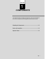
■
Assemblies
Stacker
Pick roller
Pad ASSY
Guide A ASSY
●1-5
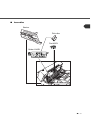
Operator Panel
The operator panel is located on the upper right hand side of the scanner. The panel consists of an LCD
display (16 characters x 2 lines), LEDs and buttons.
■
Arrangement
Operator panel
Operator panel
●1-6
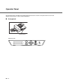
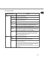
■
Button and LED
Name of the button and
LED
Button
Function
Next
Displays the next LCD screen.
Previous
Displays the previous LCD screen.
Moves the cursor to the left.
Moves the cursor to the right.
Exit
When you are entering settings on the Operator panel, pressing this
button returns you immediately to the Scanner Ready screen.
Enter
Enters the parameter currently selected by the cursor.
Send To/
Start
Operational only when Manual start mode is set or the Read lamp
lights; Starts the reading when video interface option is used. Some
application software packages make use of this button.
Stop
When the Check LED lights, pressing this button releases the error
status (turns off Check and returns to the Scanner Ready screen).
Operational only during the reading operation; stops the reading
when the video interface option is used.
Also turns off the Check lamp.
LED
Indicates that the scanner is On.
Read
Indicates the scanner is reading or ready to read.
Check
If lit, this indicates that an alarm occurred. Pressing the Stop button
turns the Check lamp Off.
If it blinks at one second intervals, this means that a jam or Multi feed
has been detected. If the problem is jammed paper, removing the
jammed paper turns off the Check lamp. If the problem is Multi feed,
pressing the Stop button turns off the Check lamp.
If it blinks at four seconds intervals, this means that cleaning the ADF
is necessary.
●1-7
●1-8
CHAPTER
2
INSTALLATION AND CONNECTIONS
The chapter describes how to install and connect the scanner.
Confirm of the Manufacturing Labels.......................................2-2
Placing the scanner....................................................................2-3
●2-1
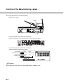
Confirm of the Manufacturing Labels
This section describes how to check the labels.
Position of two labels
Label A
Label B
Label A (Example; your actual label may differ)
Indicates regulations and standards to which this scanner conforms.
Label B (Example; your actual label may differ)
Indicates product information as follows:
Model name
MODEL
Specification number
PART NO.
Serial number
Production date
SER. NO.
Weight
DATE
fi-4340C
PA03277-B002
******
******* 15Kg
100-240V,1.6-0.7A
NOTICE
Serial Number for dual interface(i.e. SCSI/USB) model is 700001 or later.
●2-2
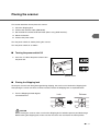
Placing the scanner
This section describes how to place the scanner.
1. Place the Shipping lock.
2. Connect the interface cable (USB/SCSI).
3. Set the SCSI ID and the SCSI terminator (When using SCSI interface).
4. Mount the Stacker.
5. Connect the power cable.
Turn the power switch off, before placing the scanner.
Turn the power switch off as follows:
■
Turning the power switch Off
1. Press the “O” side of the power switch to turn
the power Off.
Power OFF
Power On
Power switch
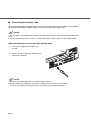
■
Placing the Shipping lock
To keep the scanner from being damaged during shipping, the carrier unit is fixed with a Shipping lock.
After placing the carrier unit where it will be installed, release the Shipping lock as explained below.
1. Turn the Shipping lock 90 degrees
counterclockwise.
Lock
Release
CAUTION
Before moving the scanner, make sure that the Shipping lock is locked to prevent possible damage.
Before locking the Shipping lock, make sure that the carrier has returned to the home position.
●2-3
■
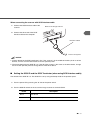
Connecting the interface cable
When running Windows 95 or Windows NT 4.0, connect the SCSI interface cable. When running Windows
98, Windows ME, Windows 2000 or Windows XP, connect either USB or SCSI cable.
NOTICE
1. If the scanner is connected to the computer with both interface cables, USB interface connection will be
used.
2. Do not connect the scanner to 2 PCs, one with USB Interface and the other one with SCSI interface.
When connecting the scanner with USB interface cable.
1.
Connect the USB interface cable to the
scanner.
2. Connect the other end of the USB interface
cable to the computer.
NOTICE
1. Be sure to use USB cable which is provided with the scanner.
2. When connecting to a USB hub, use the first stage hub that is closest to the computer.
If you use a the second or later hub stages, the scanner may not operate properly.
●2-4
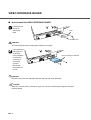
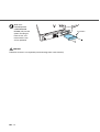
When connecting the scanner with SCSI interface cable.
1. Connect the SCSI interface cable to the
scanner.
Back of the Image scanner
2. Connect the other end of the SCSI
interface cable to the computer.
Interface cables
To the host system
NOTICE
1. Factory default for the SCSI terminator is On. If the scanner is in the middle of the daisy chain or of two
devices, turn the scanner termination Off via the operator panel.
2. The factory default for the SCSI ID is 5. If the ID of the scanner is the same as the other device, change
the ID via the operator panel or change the ID of the other device.
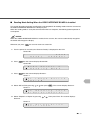
■
Setting the SCSI ID and the SCSI Terminator (when using SCSI interface cable)
The default of the SCSI ID is 5. The SCSI ID is set by using the Setup mode of the operator panel.
1. Turn the power Off by pressing the “0” side of the power switch.
2. Turn the SCSI-ID switch on the rear of the image scanner to set the SCSI-ID.
ID No.
Description
0 to 7
Can be set
8, 9
Return to default (Available ID NO. = 5) if set to 8 or 9.
●2-5
3. Set the SCSI terminator switch on the rear of the image scanner to ON or OFF.
NOTICE
The SCSI terminator switch is set to ON before shipment from the factory. When the image scanner is
located in the middle of a SCSI daisy chain, change the terminator setting to OFF.
When the image scanner is located at the end the daisy chain, set the terminator to ON.
■
Mounting the Stacker
1. Press in the bottom of the pins on both sides of the stacker with
your fingertips, and insert the stacker pins until they slot into the
holes on the image scanner.
■
Stacker
Connecting the power cable
1. Connect the power cable to the power inlet of the device and a power outlet.
Power outlet
for North America
Power inlet
Power cable
for Europe
●2-6
CHAPTER
3
HOW TO INSTALL THE DEVICE
DRIVER
This chapter describes how to install this software.
Procedure....................................................................................3-2
●3-1
Procedure
For details on how to install the device driver, refer to the attached installation guide and the device driver's
user's guide in device driver’s CD.
●3-2
CHAPTER
4
OPERATING INSTRUCTIONS
This chapter describes this scanner’s operations.
Refer to the “Cleaning and Maintenance” manual for routine scanner
maintenance.
Turning the Power On ................................................................4-2
Waking up the Scanner from the Low Power Mode ................4-3
Manual Feed Mode Setting ........................................................4-4
Loading Documents on the ADF...............................................4-5
Loading Documents on the Document bed .............................4-9
Loading Documents Larger than the Document bed..............4-10
Reading a Page from a Thick Book...........................................4-11
Clearing Paper Jams ..................................................................4-12
●4-1
Turning the Power On
This section describes how to turn the power On.
Press the “I” side of the power switch. The power turns On and the green Power lamp at the operator panel
lights.
Power OFF
Power On
●4-2
Waking up the Scanner from the Low Power Mode
This section describes how to wake up the scanner from the Low Power Mode.
To wake up the Scanner, simply press a button, set the papers on the ADF, or send a command to scan
from the host computer.
NOTICE
As an ENERGYSTAR® partner, PFU Limited declares that this scanner meets the ENERGYSTAR® guidelines
for energy efficiency.
●4-3
Manual Feed Mode Setting
In this mode, the scanner waits for some predetermined time before issuing a “Paper Empty” message
after all documents are read. This predetermined time (time-out limit) is specified in the Setup mode.
Therefore, you can set the next documents on the ADF paper chute without interrupting the reading
operation.
The procedures for setting the manual feed mode are as follows:
1. Turn the power On and verify that “Scanner Ready” is displayed on the LCD.
Screen M1
R
2. Press
e
a
d
y
X
X
X
X
X
X
X
e
c
M
t
o
d
0
e
c
e
t
e
d
1
?
F
e
e
X
0
X
>
then the scanner displays Screen M2.
Screen M2
M
3. Press
o
R
d
e
e
a
d
S
i
e
n
l
g
then the scanner displays Screen M3
Screen M3
.
M
M
4. Press
o
M
d
a
e
n
u
S
a
e
l
l
e
F
then the scanner displays Screen M4.
Screen M4
M
0
=
1
N
5. Select “Yes” by pressing
o
M
/
a
Y
n
e
u
s
. Then press
a
l
d
.
6. Press
to return to the “Scanner Ready” screen. Note that “Manual Feed” is shown on the LCD.
This means that the scanner is in Manual Feed mode.
Screen M1
M
R
●4-4
a
e
n
a
u
d
a
y
l
X
X
X
X
X
X
X
X
0
X
>
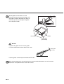
Loading Documents on the ADF
NOTICE
Be sure to change the position of the Shipping lock according to the Chapter2 "Placing the Shipping
lock (page 2-3)" procedure before operation.
ADF paper chute
ADF
Guide
Guide lever
ADF lever
Stacker
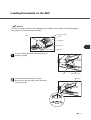
Lift up the ADF paper chute and lock the bar in its
operating position.
Bar
Fan the sheets before setting a stack of
documents on the ADF paper chute. For details
see the next page.
Operating Position
Document
10mm
●4-5
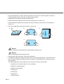
• Place the documents face down, with the top to the left as shown in A. (The long side is the top for
landscape mode and the short side is the top for portrait mode.)
• Holding both ends with both hands, lift the documents.
• Hold the documents tightly with your left hand and bend them as shown in B.
• Grip the documents tightly with your right hand, loosen the grip of your left hand, and straighten as
shown in C.
• Even up the feed edge of the batch of paper as shown in D.
A
B
Top
AB
D
C
(For portrait mode)
C
NOTICE
Reduce the batch size of the documents if Multi feed or mispick occurs.
NOTICE
Note the following when preparing the paper.
• Remove paper clips and staples. Flatten the staple holes.
•
A preliminary document feed test may be necessary to avoid unexpected errors. If document slip or
jam in the ADF (JAM error) or Multi feed occurs frequently, read the documents manually using the
Document bed.
The following documents may be difficult to be scanned successfully with the ADF:
●4-6
-
Documents of non-uniform thickness (e.g. envelopes)
-
Wrinkled or curled documents
-
Folded or torn documents
-
Tracing paper
-
Coated paper
-
Carbon paper
-
Carbonless paper
-
Photosensitive paper
-
Perforated or punched documents
-
Documents that are not square or rectangular
-
Very thin documents
• Do not use the following type documents for scanning with the ADF.
-
Paper-clipped or stapled documents
-
Documents on which the ink is still wet
-
Documents smaller than A8 (portrait) size
-
Documents wider than A3 or 11 in. x 17 in. size
-
Documents other than paper such as fabric, metal foil, or transparencies
• When using the ADF, the leading edge of all document sheets must be evenly aligned. Make sure that
curling at the leading edge is withtin the following toleranaces:
More than 30mm
Feed direction
Less than
3mm
Top of the paper
Feed direction
More than 30mm
Less than
5mm
Read surface
Top of the paper
Read surface
• To avoid skewing, do not feed documents of different widths during the same batch.
!
Adjust the stacker extension to the paper
size.
Stacker
ADF paper chute
●4-7
"
Set the guides so that there is a small
clearance between the document edges and
the guides. Load the document face down on
the ADF paper chute and adjust the guides
to the document width.
Guide
Document
Guide leber
(Both sides)
NOTICE
• Squeeze the guide lever to free the guides.
• Do not load document stacks thicker than 8 mm.
max.8 mm
(0.32")
• Set the guides so that they touch the document sides.
#
After the read command is issued from the host system and the documents are read, scanned
documents are expelled into the stacker for removal.
●4-8
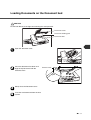
Loading Documents on the Document bed
CAUTION
Do not look directly at the light source during the read operation.
Document cover
Document holding pad
Document bed
Open the document cover.
Place the document face down and
align the top left corner with the
reference mark.
!
Slowly close the Document cover.
"
Issue the read command from the host
system.
eference mark
●4-9
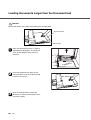
Loading Documents Larger than the Document bed
CAUTION
Do not look directly at the light source during the read operation.
Document bed
Document
Open the Document cover to an angle of
approximately 90 degrees, and lift up the
cover (in the direction of the arrow) to
remove it.
Place the document face down on the
Document bed. Issue the read command
from the host system.
!
After the read operation, remove the
document, re-attach the Document cover
and close it gently.
● 4 - 10
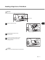
Reading a Page from a Thick Book
CAUTION
Do not look directly at the light source during read operation.
Thick book
Open the Document cover.
Place the book face down on the
Document bed.
!
Issue the read command from the host
system. Keep the cover open for the
reading operation.
NOTICE
Do not move the book during the read operation.
● 4 - 11
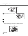
Clearing Paper Jams
Paper
ADF
ADF lever
Remove all the documents from the ADF paper chute
Pull the ADF lever to open the ADF.
!
Remove the jammed document(s).
NOTICE
• Inspect the paper and the paper path. Make sure no staples, paper clips or other materials caused
the jam. All staples and paper clips should be removed from all documents before scanning.
• Be careful not to pull the spring for the Pick while removing a jammed document.
Spring for the Pick
"
Close the ADF.
● 4 - 12
CHAPTER
5
ADF DOCUMENT SPECIFICATION
This chapter describes the document size and document quality required to
use the ADF successfully.
Document Size............................................................................5-2
Document Quality.......................................................................5-3
Maximum ADF Capacity.............................................................5-5
Areas not to be Perforated ........................................................5-6
Grounding Color Areas..............................................................5-7
Multi Feed Detection Conditions...............................................5-8
Job Separation Sheet.................................................................5-9
●5-1
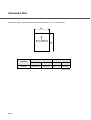
Document Size
The following figure shows document sizes that the scanner can read using the ADF.
Maximum
Minimum
Scanner
fi-4340C
A
B
A
B
216 (8.5 in)
356 (14 in)
53 (2.1 in)
74 (2.9 in)
(Unit : mm)
●5-2
Document Quality
This section describes the types and weights of paper that the scanner can read and precautions in
preparing documents to ensure maximal scanner functioning.
■
Document type
The recommended paper type for documents is as follows:
• Woodfree paper
• Wood containing paper
When using documents of a paper type other than the above, perform a test-scanning with a few sheets of
the same type before executing the actual task in order to check whether or not the documents can be
scanned.
Any paper can be used on the Document bed. However, the ground color specification must satisfy the
specification described in the Grounding Color Area section.
■
Paper weight
The paper weight should fall within the following ranges:
• 52 to 127 g/m2 (13.9 to 34 lb), 127g/m2 (34lb) for A8
■
Precautions
A preliminary document feed test may be necessary to avoid unexpected errors. If document slip or jam in
the ADF (JAM error) or Multi feed occurs frequently, scan the documents manually using the Document
bed.
The following documents may be difficult to be scanned successfully with the ADF:
• Documents of non-uniform thickness (e.g. envelopes)
• Wrinkled or curled documents (Refer to NOTICE in this section)
• Folded or torn documents
• Tracing paper
• Coated paper
• Carbon paper
• Carbonless paper
• Photosensitive paper
• Perforated or punched documents
●5-3
• Documents that are not square or rectangular
• Very thin documents
Do not use the following type documents for scanning with the ADF.
• Paper-clipped or stapled documents
• Documents on which the ink is still wet
• Documents smaller than A8 (portrait) size
• Documents wider than A3 or 11 in. x 17 in. size
• Documents other than paper such as fabric, metal foil, or transparencies
NOTICE
• When scanning semi-transparent documents, set the density to light to avoid a bleed through.
• Carbonless paper contains chemical substances that may harm the Pad or rollers (e.g. Pick roller).
Pay attention to the following:
Cleaning
: If mispicks occur frequently, clean the Pad and Pick roller. For details on
cleaning method, refer to the “Cleaning and Maintenance” manual.
Replacing parts
:The service life of the Pad and Pick roller may be shortened compared to the
case of scanning wood containing paper documents.
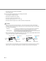
• When using the ADF, the leading edge of all document sheets must be evenly aligned. Make sure that
curling at the leadin edge is withtin the following toleranaces:
More than 30mm
Feed direction
Less than
3mm
Top of the paper
More than 30mm
Feed direction
Less than
5mm
Read surface
Top of the paper
Read surface
• To prevent rollers from becoming dirty, avoid scanning documents containing large areas written or
filled in pencil. If scanning of such documents is inevitable, clean the rollers more frequently.
●5-4
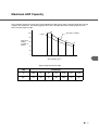
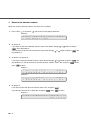
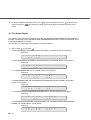
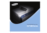
Maximum ADF Capacity
The maximum number of sheets that can be loaded on the ADF paper chute is determined by the size and
weight of the documents. The following graph shows the maximjum documents loading capacity of the
ADF based on paper weight.
100
100
A4/Letter or smaller
Legal
80
80
79
63
ADF chute
60
loading
(number of
pages)
40
61
49
50
40
20
0
52
64
81
104
127
ADF Capacity (g/m2)
Paper weight conversion table
Unit
Conversion
lb
13.9
17
20
24
27.9
34
41.8
g/m2
52
64
75
90
104
127
157
●5-5
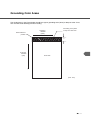
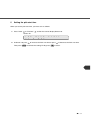
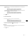
Areas not to be Perforated
With the ADF, perforations in the shaded areas may cause errors. If you must read data from such a paper,
use the Document bed:
Read reference
position
10
79
Center of
sensor arm
79
Center of
sensor arm
10
Top of paper
15
Front
side
Feeding
direction
Bottom of paper
35
Center of paper
●5-6
(Unit : mm)
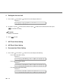
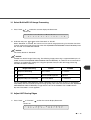
Grounding Color Areas
The shaded area in the Figure below should have paper grounding color (white) or drop-out color. If not,
turn the white level following Off when reading.
Read reference
position
Scanning
direction
(main)
Grounding color (white
or drop-out color area
3
Scanning
direction
(sub)
Front Side
(Unit : mm)
●5-7
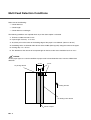
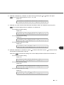
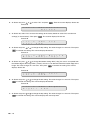
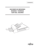
Multi Feed Detection Conditions
Select one of the following:
• Check thickness
• Check length
• Check thickness and length
The following conditions are required when any of the above option is selected:
1 Thickness: 0.065 mm to 0.15 mm
2 Paper length accuracy: 1% or less
3 Any black print at the center of the leading edge of the paper is not allowed. (10 mm x 10 mm)
4 No binding holes are allowed within 35 mm of the middle (halfway point) along the center of the paper.
5 Printing duty: 12 % or less
6 The deviation of the amount of transparent light on the base color area should be less than 10 %.
NOTICE
Certain paper types or a certain condition of paper result in lower detection rates in terms of Multi feed
detection.
35 mm
10 mm
No printing allowed
Feeding direction
No binding holes allowed
Center of Paper
●5-8
Job Separation Sheet
1 Shape
The following shows the typical format of the job separation sheet.
15
Top of paper
15
Feeding direction
Bottom of paper
Center of paper
(Unit : mm)
2 Paper conditions
Paper width must be A4 or larger (210 mm or larger in width).
●5-9
● 5 - 10
CHAPTER
6
OPERATOR PANEL MESSAGE
This chapter describes the components of the scanner, part names, and LED
indicators. After unpacking the scanner, confirm that all components have
been received by checking them against the list in the first section.
Counter Display ..........................................................................6-2
Operation status .........................................................................6-3
Temporary error..........................................................................6-4
Alarm ...........................................................................................6-5
●6-1
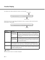
Counter Display
The displays for the Paper and Abrasion counters are shown below:
Paper counter
R
e
a
d
y
X
X
X
X
X
X
X
X
0
X
>
Abrasion counter
Simultaneously press the
and
panel display as shown below:
R
arrow buttons for at least 1 second, to switch to the Life counter
e
a
d
y
*
X
X
X
X
X
X
0
>
Life counter
Counter
Function
Paper counter
When the
button is pressed
for at least 1 second
The paper counter counts the number of scanned sheets from
the start of reading until Paper Empty or an error is detected.
The counter is automatically reset at the start of reading. The
counter is used for checking the number of the sheets scanned
in one batch.
When the
button is pressed
for at least 1 second
This counter increments each time a document is scanned. It is
not initialized until the power is turned off. The counter can be
used, for example, for checking the number of sheets that have
been scanned in one day.
Abrasion counter
The abrasion counter counts the accumulated number of scanned sheets. This
counter increments every 10 sheets. It is useful to check the cleaning cycle or the
parts replacement cycle. How to reset it is described in Chapter7 "SETUP MODE".
Life Counter
Keeps a cumulative count of the number of scans made after shipping.
This counter increments by 1 after every 10 scans and may be used to estimate of
the device's remaining scan life.
NOTICE
When the counter value is 0, no number is displayed.
●6-2
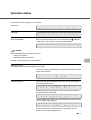
Operation status
The operation status messages are as follows:
<Power-on>
W a
r
N
w
m
i
n
g
-
u
p
R
e
a
d
i
n
N
o
w
!
!
x
x x
!
<Reading>
<Low Power Mode>
o
g
When the Scanner Display turns Off and the power
remains “On”, the scanner is in the Low Power Mode.
x
indicator
NOTICE
One of the following will wake up the scanner:
• Pressing any button.
• Setting the paper on the ADF.
Sending a command from the host computer.
<Waiting for Start>
(Only When the Video Interface Option is installed.)
The scanner displays the following screen when waiting for the Start
button to be pressed:
S
<Cleaning request>
t
a
r
S
t
O
W
N
!
When the ADF glass cleaning is necessary, the scanner displays
the following on the LCD:
C
l
N
e
o
a
w
n
R
A
e
D
a
F
d
i
G
n
l
g
a
!
s
s
When the Pick roller cleaning is necessary, the scanner displays
the following on the upper line:
C
l
N
e
o
a
w
n
R
P
e
i
a
c
d
k
i
r
n
o
g
l
!
l
r
e
When the ADF glass and the Pick roller cleaning are necessary, the
scanner displays the following:
C
C
l
l
e
e
a
a
n
n
P
A
i
D
c
F
k
r
G
o
l
l
a
l
s
r
e
s
Clean the Pick roller or the ADF glass in accordance with the
manual, “Cleaning and Maintenance”.
●6-3
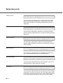
Temporary error
<Hopper empty>
P
a
p
e
E
r
m
p
t
y
This message is displayed if there is no more paper on the ADF
paper chute during a read operation in ADF mode. Fill the ADF
paper chute with paper. To enable the read operation, press the
stop button.
<Jam>
P
a
p
e
J
r
a
m
This message is displayed if a document is jammed in the ADF.
See the “Cleaning and Maintenance” manual for removing jammed
documents.
<ADF cover open>
A
D
F
-
C
o
v
e
r
O
p
e
n
This message is displayed if the ADF is not closed completely.
Close the ADF completely. To enable the read operation, close the
ADF completely.
<Multi feed error>
M
u
l
t
i
F
e
e
d
This message is displayed when the ADF detects the Multi feed
error. Check the document and re-scan the document.
<No Ink Cartridge>
N
o
I
n
k
C
a
r
t
r
i
d
g
e
This message is displayed when the print cartridge is not put in fi434PR (Imprinter). Please place the cartridge.
<Print Error>
P
r
i
n
t
E
r
r
o
r
This message is displayed when the print position mark of fi-434PR
(Imprinter) is set to the area which is out of the paper path or when
the stacker is full of ducuments. Please set the fi-434PR (Imprinter)
to the correct position or take the paper away from the stacker.
●6-4
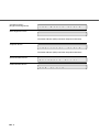
Alarm
One of the following messages is displayed if an error occurs in the scanner. If one of the following error
messages is displayed, turn the power Off and then On again. If the same message is displayed, contact
your service representative.
<Optical alarm front>
O
F
p
r
t
o
i
n
c
t
a
l
B
p
a
t
c
i
k
c
a
S
l
i
O
M
e
c
h
F
a
l
n
a
i
t
c
<Optical alarm back>
<FB mechanism alarm>
S
i
A
d
l
e
a
r
m
d
A
e
l
a
r
m
b
a
e
l
A
l
d
a
r
m
NOTICE
When the total number of sheets scanned by the ADF is less than 100, the message above and the
message below are displayed alternately. Remove the bracket (Shipping Lock) that holds the carrier in
place.
S
h
i
f
u
s
e
f
u
s
e
T
r
a
n
s
o
r
y
A
l
R
O
M
A
l
A
l
r
m
C
h
L
e
o
c
c
k
k
M
o
t
o
r
L
a
m
p
I
m
g
M
e
m
E
E
P
F
A
N
p
p
i
n
g
A
l
a
r
l
a
r
m
A
l
a
r
a
r
m
a
r
m
<Motor fuse alarm>
m
<Lamp fuse alarm>
A
<Image transfer alarm>
m
<Memory alarm>
<EEPROM alarm>
<FAN alarm>
a
●6-5
<IPC Board alarm>
(Image Processing board)
I
P
C
B
o
a
r
d
A
l
a
r
m
<Self-diagnostics Error>
The Power indicator (LED) and Check lamp blink alternately.
<Imprinter Alarm>
I
m
p
r
i
n
t
e
r
A
l
a
r
m
The Power Indicator (LED) and Check lamp blink alternately.
<SCSI Controller Alarm>
H
a
r
U
S
B
d
w
a
r
e
A
l
a
r
E
<USB Controller Alarm>
●6-6
m
r
r
o
r
CHAPTER
7
SETUP MODE
This chapter describes the setup mode of the scanner.
Activating the Setup Mode ........................................................7-2
Contents of the Setup Mode......................................................7-3
●7-1
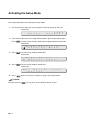
Activating the Setup Mode
This section describes how to activate the setup mode.
1. Turn the power On. Then the scanner displays “Scanner Ready” on the LCD.
Screen M1
R
e
a
d
y
X
X
X
X
X
X
X
X
0
X
>
2. If the scanner does not have a video interface option, go to the procedure step 3.
Press
then the scanner with the video interface option displays Screen M2.
Screen M2
M
3. Press
o
R
d
e
e
a
d
S
i
e
n
l
g
e
c
M
t
o
d
0
e
c
e
t
e
d
1
?
F
e
e
then the scanner displays Screen M3.
Screen M3
M
M
4. Press
o
M
d
a
e
n
u
S
a
e
l
l
e
F
then the scanner displays Screen M4.
Screen M4
M
5. Press
0
=
1
N
o
M
/
a
Y
n
e
u
s
a
l
. Now the scanner is at Screen 1 (page 7-5) in Setup mode.
NOTICE
Any time you press
●7-2
d
, you can return to the “Scanner Ready” screen.
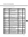
Contents of the Setup Mode
This section describes the contents of the setup mode.
Item
Description
Selectable
parameters
Default
Multi feed check
Specifies the Multi feed detection. Multi
feed is detected by checking the
document length and/or paper
thickness.(*1)
No/Yes
No
Length check
=No/10/15/20 mm
Specifies the document length to enable
Multi feed detection sets the document
length.
Tolerance:
No/10/15/20mm
No
IPC pre-setting
Document:
Scanner automatically sets the
No
recommended reading parameters. 3 sets
1: Sharpen
No
of parameters are available when IPC-4D
2: Darken Character
is not installed.
3: Copy Quality
4
Resetting of
abrasion counter
Resets the abrasion counter.
5
Pick start time
setting
Specifies the time from document Insertion
Time:
to the start of picking. User can select the
0.2 to 29.8 sec
most comfortable Pick start time for the job.
6
Specifies the time the scanner waits for
Time-out limit setting the next document insertion after the last
document was scanned.
7
ADF front offset
setting(*2)
Specifies the horizontal and vertical offset Offset:
of the front side image when using the
H:-2 to +3 mm
ADF.
V:-2 to +3 mm
Offset:
H: 0 mm
V: 0 mm
8
ADF back offset
setting(*2)
Specifies the horizontal and vertical offset Offset:
of the back side image when using the
H:-2 to +3 mm
ADF.
V:-2 to +3 mm
Offset:
H: 0 mm
V: 0 mm
9
Document bed
offset setting(*2)
Horizontal and vertical offset of the FB
image is specified.
Offset:
H:-2 to +3 mm
V:-2 to +3 mm
Offset:
H: 0 mm
V: 0 mm
10
IPC status display
(*3)
Displays whether or not the image
processing board (IPC-4D) and the
Imprinter option are installed.
---
---
11
Low Power Mode
setting
Changes the default setting of the duration 5 min.
for power save.
to 60 min.
15 min.
12
Select Interface
Selects the interface when the scanner
has a board in the third party Slot.
Auto
13
Display TPS Board
ID Number
Displays the ID number of the board which
--is installed in the third party Slot.
No
1
2
3
---
Time:
27 values from
1 to 1999 sec
Auto/Standard/Tps
---
1.0 sec
30 sec
---
●7-3
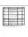
(Continued)
No
Description
IPC mode
When the IPC-4D image processing board
is installed in the third party Slot, select
Standard/IPC4D
this IPC-4D board or the image processing
circuit built in the scanner.
Standard
ADF Edge Erasing
Left/Right:
0 to 15 mm
Adjusts the edge areas to be erased from
Top:
the image scanned by the automatic
0 to 15 mm
document feeder (ADF).
Bottom:
-7 to 0 mm
Left/Right:
0 mm
Top:
0 mm
Bottom:
0 mm
FB Edge Erasing
Left/Right:
0 to 15 mm
Adjusts the edge areas to be erased from Top:
the image scanned by the flat bed (FB).
0 to 15 mm
Bottom:
0 mm
Left/Right:
0 mm
Top:
0 mm
Bottom:
0 mm
Select read color
Selects the color to be read in unicolor
reading.
G
Gray mode
Switches between quality priority scanning
Normal/
and speed priority scanning when
Fast
scanning grayscale images.
Fast
Remaining ink
Displays the remaining amount of ink
when the Imprinter option is attached and
Reset/No
resets the remaining ink counter when
replacing the ink.
No
Print No.
Selects printing of Nos. when the Imprinter
on/off
option is attached.
off
14
15
16
17
18
19
20
Selectable
parameters
Item
R/G/B/W
*1) Some restrictions apply to the detection of a Multi feed.
*2) This offset refers to the difference from the value adjusted by automatic offset adjustment.
*3) The display message may differ depending on the option installed.
●7-4
Default
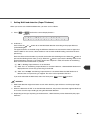
1
Setting Multi feed detection (Paper Thickness)
When you set the use of Multi feed detection, you must set it as follows:
1. Press
or
and let the scanner display Screen 1.
Screen 1
!
=
0
N
1
o
/
M
Y
u
e
l
s
t
i
1
/
F
2
e
:
e
S
d
t
o
p
2. At Screen 1.
Press either the
or
(transmitted light).
button to set the Multi feed detection according to the paper thickness
The paper thickness is checked using the difference between two consecutive sheets of paper fed
from the ADF. On this screen, select whether or not to check for Multi feeding, and select the error
processing.
Each time either of these buttons is pressed, the location of the blinking moves. When the
button is
pressed, the blinking moves from (1) to (3). When the
button is pressed, the blinking moves in the
opposite direction. However, if the setting by the host computer is valid, the location of the blinking
does not move when either button is pressed.
(1) “No” is blinking: Paper thickness is not checked.
(2) “Yes” and “1” are blinking: Paper thickness is checked. However, a detected Multi feed error is
displayed on the screen only; processing is continued.
(3) “Yes” and “2: Stop” are blinking: Paper thickness is checked. When the Multi feed error is
detected, the scan processing is stopped. The error is then reported to the host.
If you want to disable the Multi feed, select “No” then press
. Press
to return.
NOTICES
1. Multi Feed detection might have better results when both the paper thickness and the paper length
are used.
2. When the document in ADF is not the Multi fed document, the previous document might be Multi fed,
in case the scanner stops feeding by using the Multi feed detection.
3. Depending on the type of printing on the document, a Multi feed may not be detected by the paper
thickness.
●7-5
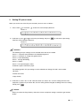
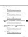
2
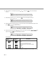
Setting Multi feed detection (Paper Length)
1. Press
or
and let the scanner display Screen 2.
Screen 2
!
=
0
N
2
o
/
L
Y
e
e
n
s
g
t
1
h
/
2
C
:
h
S
e
t
c
o
k
p
2. Press either the
or
button to set Multi feed detection according to paper length. The paper
length is checked using the difference between two consecutive sheets of paper fed from the ADF.
Each time either of these buttons is pressed, the location of the blinking moves. When the
button is
pressed, the blinking moves from (1) to (3). When the
button is pressed, the blinking moves in the
opposite direction. However, if the setting by the host computer is valid, the location of the blinking
does not move when either button is pressed.
(1) “No” is blinking: Paper length is not checked.
(2) “Yes” and “1” are blinking: Paper length is checked. However, a detected Multi feed error is
displayed only on the screen; processing is continued.
(3) “Yes” and “2: Stop” are blinking: Paper length is checked. When the Multi feed error is
detected, the scan processing is stopped. The error is then reported to the host.
If you want to disable the Multi feed, select “No” then press
After pressing
. Press
to return.
, the scanner displays the Screen 3.
Screen 3
!
=
0
1
2
0
/
1
1
5
L
/
e
2
n
0
g
t
m
h
m
3. Press either the
or
button to set Multi feed detection (paper length). When the
button is
pressed, the blinking moves from (1) to (3). When the
button is pressed, the blinking moves in the
opposite direction.
(1) The “10” is blinking: Threshold is 10mm
(2) The “15” is blinking: Threshold is 15mm
(3) The “20” is blinking: Threshold is 20mm
●7-6
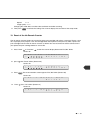
3
Setting IPC pre-set mode
When you set the use of the IPC pre-set mode, you must set it as follows:
1. Press “Next”
or “Previous”
and let the scanner display Screen 4.
Screen 4
0
N
!
=
3
o
I
P
C
P
r
e
-
S
e
2. At Screen 4, press
or
to select the pre-Setting and press
Then the scanner displays Screen 5.
t
to activate the pre-setting.
Screen 5
0
!
3
P
r
1
e
s
U
e
s
t
e
?
I
Y
P
e
C
s
/
N
o
NOTICES
The following IPC pre-settings can be selected when IPC-4D is installed:
Preset 1: Captures texts printed on the colored background
Preset 2: Produces an image with good contrast
Preset 3: OCR Smoothing
Preset
4 Image Smoothing
Preset 5: Dither
Preset 9: Pre-printed paper (color)
Carbonless paper:Carbonless paper
The following built-in IPC pre-settings can be selected even though IPC-4D is not installed:
•Sharpen
•Darken Character
•Copy Quality
3. At Screen 5, select “Yes” or “No”. Note that when you select “Yes”, the IPC setting from the Host
computer is ignored. If you select “No”, the IPC setting will be changed according to the host setting.
Finally press
.
NOTICE
When you select the Copy Quality, select the scanner and printer settings carefully to get the best
quality.
●7-7
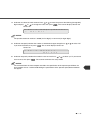
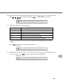
4
Reset of the abrasion counter
When you reset the abrasion counter, you must set it as follows:
1. Press “Next”
or “Previous”
and let the scanner display Screen 6.
Screen 6
A b r
Ro l l e r
0 4
P i ck
!
=
a
/
s i
Pa d
o
n
C
N
2. At Screen 6;
If you want to reset the PickRoller counter, select “Pick Roller” through
T
or
button and press
. Go to procedure 3.
If you do not want to reset the Pad counter, select “Pad” through
to procedure 3.
or
button and press
. Go
or
button and press
. Go
3. At Screen 7 or Screen 8;
If you want to reset the abrasion counter, select “Reset” through
to procedure 4. If you do not want to reset the abrasion counter, select “No” and press
press
to return.
Screen 7
!
=
0
X
4
X
X
1
X
P
4
X
X
2
X
c
X
i
X
P
X
a
X
d
k
R
e
s
e
t
C
/
N
N
T
o
R
e
s
e
t
C
/
N
N
T
o
Screen 8
!
=
0
X
4. At Screen 9
If you want to reset the abrasion counter, select “Yes” and press
.
If you do not want to reset it, select “No” and press
to return.
.Press
Screen 9
!
0
4
-
3
R
e
s
e
t
●7-8
o
N
N
o
w
/
Y
e
s
.Finally
5
Setting the pick start time
When you set the pick start time, you must set it as follows:
1. Press “Next”
or “Previous”
and let the scanner display Screen 10.
Screen 10
0
1
!
=
2. At Screen 10, press
Then press
5
.
P
0
i
S
c
e
k
c
s
t
a
to increase the Pick start time or press
to activate the setting. Finally press
r
t
to decrease the Pick start time.
to return.
●7-9
6
Setting the time-out limit
1. Press “Next”
or “Previous”
and let the scanner display Screen 11.
Screen 11
!
=
0
3
2. At Screen 11, press
6
0
T
S
i
e
m
c
e
-
o
u
to increase the number or press
t
to decrease the time-out limit. Then press
to activate the setting.
NOTICE
Default is 30 seconds.
3. Press
to return.
7
ADF Front Offset Setting
8
ADF Back Offset Setting
9
Document bed Offset Setting
1. Press “Next”
-
or “Previous”
and let the scanner display the following:
For an ADF front offset setting
Screen 12
!
-
0
7
C
h
A
a
D
n
F
g
F
?
.
e
O
N
f
o
f
/
s
Y
e
e
t
s
D
n
F
g
B
?
.
e
O
N
f
o
f
/
s
Y
e
e
t
s
O
e
f
?
f
g
s
N
e
o
t
/
Y
e
s
For an ADF back offset setting
Screen 13
!
-
0
8
C
h
A
a
For a Document bed offset setting
Screen 14
!
● 7 - 10
0
9
C
h
F
a
B
n
2. At Screen 12,Screen 13, or Screen 14, select “Yes” by pressing the
or
button, then press
. The scanner displays Screen 15. (X = 7, 8, or 9)
Screen 15
!
0
d
X
e
f
1
a
R
u
e
l
t
t
u
?
r
n
N
o
t
/
o
Y
e
s
3. At Screen 15, if you want to let the offset return to default, select “Yes” otherwise “No” then press
. The scanner displays Screen 16,Screen 17 or Screen 18.
-
For an ADF front offset setting
Screen 16
!
H
-
0
=
7
+
0
2
.
0
F
m
r
m
o
(
n
+
t
:
L
H
e
f
t
)
0
B
m
a
m
c
(
k
+
:
H
L
e
f
t
)
F
m
B
m
(
H
+
:
L
e
f
t
)
For an ADF back offset setting
Screen 17
!
H
-
0
=
8
+
0
2
.
For a Document bed offset setting
Screen 18
!
H
0
=
9
+
0
2
.
0
4. At Screen 16,Screen 17 or Screen 18, press
The increment or decrement is 0.5 mm.
Then press
-
to increase the offset or press
to decrease offset.
to activate the setting. The scanner displays Screen 19,Screen 20 or Screen 21.
For an ADF front offset setting
Screen 19
!
V
-
0
=
7
+
0
3
.
0
F
m
r
m
o
(
n
+
t
:
U
V
p
)
0
B
m
a
m
c
(
k
+
:
V
U
p
)
F
m
B
m
(
V
+
:
U
p
)
For an ADF back offset setting
Screen 20
!
V
-
0
=
8
+
0
3
.
For a Document bed offset setting
Screen 21
!
V
0
=
9
+
0
3
.
0
● 7 - 11
5. At Screen 19,Screen 20 or Screen 21, press
offset. Then press
mode.
to increase the offset or press
to decrease the
to activate the setting. The scanner displays the next item of the setup
10 IPC Status Display
This function allows you to check whether or not the IPC-4D(IMAGE PROCESSING CIRCUIT BOARD) is
installed, and whether or not fi-475CMP3(JPEG COMPRESSION BOARD) is installed, and whether or not
fi-434PR(IMPRINTER) is installed.
Check whether or not the respectively option is installed as follows.
1. Press “Next”
or “Previous”
.
if an IPC4D(IMAGE PROCESSING CIRCUIT BOARD) is installed, Screen 22 will appear.
Screen 22
!
1
I
0
P
C
I
-
P
4
C
D
if an IPC4D(IMAGE PROCESSING CIRCUIT BOARD) is not installed,Screen 23 will appear.
Screen 23
!
1
0
I
N
P
O
C
if a fi-434PR(IMPRINTER) only is installed, Screen 24 will appear.
Screen 24
!
1
0
I
N
P
O
C
P
O
R
K
T
if fi-434PR(IMPRINTER) and IPC4D(IMAGE PROCESSING CIRCUIT BOARD) are installed,
Screen 25 will appear.
Screen 25
!
1
I
0
P
C
I
-
P
4
C
D
P
O
R
K
T
if a fi-475CMP3(JPEG COMPRESSION BOARD) only is installed, Screen 26 will appear.
Screen 26
!
1
0
I
N
P
O
C
J
O
P
K
E
G
if IPC4D(IMAGE PROCESSING CIRCUIT BOARD) and fi-475CMP3(JPEG COMPRESSION
BOARD) are installed,Screen 27 will appear.
Screen 27
!
● 7 - 12
1
I
0
P
C
I
-
P
4
C
D
J
O
P
K
E
G
if fi-434PR(IMPRINTER) and fi-475CMP3(JPEG COMPRESSION BOARD) are installed,Screen 28
will appear.
Screen 28
!
1
0
I
N
P
O
C
P
O
R
K
T
J
O
P
K
E
G
if fi-434PR(IMPRINTER), IPC4D(IMAGE PROCESSING CIRCUIT BOARD) and fi-475CMP3(JPEG
COMPRESSION BOARD) are installed,Screen 29 will appear.
Screen 29
!
2. Press
1
I
0
P
C
I
-
P
4
C
D
P
O
R
K
T
J
O
P
K
E
G
to return.
11 Low Power Mode Setting
1. Press “Next”
or “Previous”
and let the scanner display Screen 30.
Screen 30
!
=
1
1
2. At Screen 30, press
3
0
or
P
1
o
5
w
e
2
r
0
S
m
a
i
v
n
e
to select the time duration. A minimum of 5 min to the maximum of 60
minutes can be selected. Then press
to activate the setting.
NOTICE
The default time recommended by the ENERGYSTAR® program is 15 minutes. The default for the fi4340C scanner is 15 minutes, as recommended.
3. Press
to return.
● 7 - 13
12 Select Interface
1. Press “Next”
or “Previous”
and let the scanner display Screen 31.
Screen 31
!
=
1
A
4
u
t
I
o
n
/
t
S
e
t
r
a
f
n
a
d
c
a
e
r
d
t
I
a
n
n
t
d
e
a
r
r
f
d
a
/
c
T
e
P
S
/
Screen 31-2
!
=
1
/
4
S
NOTICE
The Screen 31 and 31-2 will appear oniy when the scanner has proper interface boards or option
boards in the third party slot.
2. At Screen 31 and 31-2, press
the setting.
or
to select the interface type. Press
if you want to change
NOTICE
1.Normally, this setting does not have to be changed.
2.When an appropriate board is installed in the third party slot of the scanner, the scanner
automatically turns off the SCSI or USB interface, activating the board in the third party slot. Screen
31 and 31-2 can be used to forcibly change the selected interface. The selected interface is then
forcibly changed.
3.The SCSI interface, USB interface and the board installed in the third party slot cannot be used at
the same time.
4.The default is Auto.
3. Press
to return.
13 Display the TPS Board ID Number
1. Press “Next”
or “Previous”
and let the scanner display Screen 32.
Screen 32
!
1
I
5
n
t
T
e
P
r
S
f
a
B
c
o
e
a
r
I
d
D
=
0
The scanner displays the ID number if the applicable board is installed.
NOTICE
If the Fujitsu video Interface Option board is installed properly, the display shows “ID=7”.
2. Press
● 7 - 14
to return.
14 Select Built-In/IPC-4D Image Processing
1. Press “Next”
or
and let the scanner display the Screen 33.
Screen 33
!
1
S
2. At Screen 33, press
6
t
I
n
a
or
P
d
C
e
r
M
d
o
/
d
I
e
P
C
-
4
D
to select “Standard” or “IPC4D”.
When “Standard” is selected, the scanner uses its built-in image processing. On the other hand, the
scanner selects the image processing of the IPC-4D(IMAGE PROCESSING CIRCUIT BOARD) when
the “IPC-4D” is installed and selected.
NOTICE
The factory default is “Standard”.
NOTICE
fi-4340C has built-in Image Processing. The following image processing is supported both by the fi4340C and the IPC-4D(IMAGE PROCESSING CIRCUIT BOARD). As a default, the scanner built-in
functions are enabled. By setting "On" using the Operator Panel, the IPC-4D image processing
overrides the built-in functions.
Image Processing
IPC-4D
fi-4340C
1
Emphasis/Smoothing
5 x 5 matrix
3 x 3 matrix
2
Outline
Pre-threshold Laplacian
Laplacian
3
Simplified Dynamic Threshold
IPC-2 like SDTC
3 x 3 max-min
The IPC-4D(IMGGE PROCESSING CIRCUIT BOARD) support of those functions is intended for
compatibility with the IPC-3/3D (except for image quality). The matrix size used in the IPC-4D(IMAGE
PROCESSING CIRCUIT BOARD) is larger than the one in the fi-4340C. The fi-4340C Built-in
Dynamic Threshold is a new algorithm.
15 Adjust ADF Erasing Edges
1. Press “Next”
or “Previous”
and let the scanner display Screen 34.
Screen 34
!
1
C
7
h
a
A
n
D
g
F
e
E
?
d
N
g
o
e
/
E
Y
R
e
S
s
● 7 - 15
2. At Screen 34, press
or
to select “Yes” and press
. Then the scanner displays Screen 35.
Screen 35
!
1
7
-
D
1
e
N
f
o
a
/
u
Y
l
e
t
s
?
3. At Screen 35, select “Yes” to return the settings to the factory default or select “No” to make new
settings (as shown below). Then press
. The scanner displays Screen 36.
Screen 36
!
T
1
o
4. At Screen 36, press
7
p
=
or
2
0
A
m
D
m
F
T
o
p
to change the top setting. The value changes in 1 mm units. Then press
to activate the setting. The scanner displays Screen 37.
Screen 37
!
B
1
t
7
m
=
3
0
A
m
D
m
F
(
+
B
:
o
U
t
p
t
)
o
m
5. At Screen 37, press
or
to change the bottom setting. With (+:Up), the area is set upward from
the bottom edge of the image. With (–:Down), the area is set downward from the bottom edge of the
image. The value changes in 1 mm units. Then press
displays Screen 38.
to activate the setting. The scanner
Screen 38
!
L
1
e
6. At Screen 38, press
7
f
or
t
A
0
4
=
D
m
F
m
L
e
f
t
to change the left setting. The value changes in 1 mm units. Then press
to activate the setting. The scanner displays Screen 39.
Screen 39
!
R
7. At Screen 39, press
1
i
7
g
or
h
5
t
A
=
D
0
F
m
R
i
g
h
to change the top setting. The value changes in 1 mm units. Then press
to activate the setting. The scanner displays the next setup item.
● 7 - 16
t
m
16 Adjust FB Erasing Edges
1. Press “Next”
or “Previous”
and let the scanner display Screen 40.
Screen 40
!
C
1
h
2. At Screen 40, press
8
a
n
or
F
g
B
e
E
?
d
N
g
o
e
/
E
Y
to select “Yes” and press
R
e
S
s
. Then the scanner displays Screen 41.
Screen 41
!
1
8
-
D
1
f
N
e
a
o
u
/
l
Y
t
e
?
s
3. At Screen 41, select “Yes” to return the settings to the factory default or select “No” to make new
settings (as shown below). Then press
. The scanner displays Screen 42.
Screen 42
!
T
1
o
4. At Screen 42, press
8
p
=
or
2
0
F
m
T
B
m
o
p
to change the top setting. The value changes in 1 mm units. Then press
to activate the setting. The scanner displays Screen 43.
Screen 43
!
B
1
t
8
m
=
3
0
F
m
B
m
(
B
+
o
:
t
U
t
p
m
)
5. At Screen 43, press
or
to change the bottom setting. With (+:Up), the area is set upward from
the bottom edge of the image. With (–:Down), the area is set downward from the bottom edge of the
image. The value changes in 1 mm units. Then press
displays Screen 44.
to activate the setting. The scanner
Screen 44
!
L
1
e
6. At Screen 44, press
8
f
or
t
F
0
4
=
B
m
L
e
f
t
m
to change the left setting. The value changes in 1 mm units. Then press
to activate the setting. The scanner displays Screen 45.
Screen 45
!
R
1
i
8
g
h
5
t
F
=
B
0
m
R
m
i
g
h
t
● 7 - 17
7. At Screen 45, press
or
to change the top setting. The value changes in 1 mm units. Then press
to activate the setting. The scanner displays the next setup item.
17 Color to be Read in Unicolor Reading
1. Press “Next”
or “Previous”
and let the scanner display Screen 46.
Screen 46
!
=
1
R
2. At Screen 46, press
9
/
G
or
R
/
e
B
a
C
d
o
l
o
to select a light source. Press
r
if you want to activate the setting.
NOTICES
1.The specification from the host computer has priority.
2.The default is G (Green).
3. Press
to return.
18 Setting the Grayscale Mode
1. Press "Next"
or "Previous"
to display Screen 47 on the LCD.
Screen 47
!
=
2. In Screen 47, press
2
N
0
o
or
r
G
m
r
a
a
l
y
/
F
M
a
o
s
d
t
e
to select "Normal", "Fast".
"Normal" refers to quality priority mode. When "Normal" is selected, scanning is performed at a
quality higher than that of the Fast mode.
"Fast" refers to the regular mode. When "Fast" is selected, scanning is performed at the machine
defaults for image quality and speed.
The lower display of Screen 47 is switched as follows:
1.”Normal/Fast" is displayed, and "Normal" flashes.
2."Normal/Fast" is displayed, and " Fast" flashes.
Switch between the above states as follows:
● 7 - 18
Press
: The lower display of Screen 47 is switched cyclically in order from 2 to 1.
Press
: The lower display of Screen 47 is switched cyclically in order from 1 to 2.
Speed:
2>1
Image quality: 1 > 2
Changing this mode does not affect color and black-and-white scanning.
3. Then press
to activate the setting. The scanner displays the next item of the setup mode.
19 Reset of the Ink Remain Counter
The ink remain counter checks the service life of the print cartridge and makes a message “Please a new
Ink” to prompt you to prepare a new ink cartridge.When the imprinter cannot print any more, replace the
print cartridge and reset the Ink remain counter as follows.You must reset the ink remain counter even if
you replace the print cartridge before its service life.
1. Press “Next”
or “Previous”
and let the scanner display Screen 48.First,”No” blinks.
Screen 48
!
=
2. press
2
1
I
n
k
r
R
e
e
m
s
a
e
i
t
n
/
N
o
r
R
e
e
m
s
a
e
i
t
n
/
N
o
,then “Reser” blinks.(Screen 49).
Screen 49
!
=
3. Press
2
1
I
n
k
.The reset execution screen appears.First,”No” blinks.(Screen 50)
Screen 50
!
4.
Press
2
1
-
1
R
e
s
N
e
o
t
/
N
e
o
s
w
Y
s
N
e
o
t
/
N
e
o
s
w
Y
,then “Yes” blinks.(Screen 51)
Screen 51
!
2
1
-
1
R
e
● 7 - 19
5. Press
to perform reset operation.The ink remain indicator returns to
(Screen 52)
.
Screen 52
!
=
6. Press
2
1
I
n
k
r
R
e
e
m
s
a
e
i
t
n
/
N
o
X
X
X
X
X
X
X
0
X
>
.The LCD returns to the “Ready” screen.
Screen 53
R
e
a
d
y
X
20 Setting the Numbering Print Function(for fi-434PR Imprinter Option)
You can specify conditions of the numbering print function from the operator panel when the scanner is
equipped with the fi-434PR imprinter.The numbering counter increments 1 each a sheet of paper is
read.Numbering print starts with a top margin of 7mm.
1. Press “Next”
or “Previous”
and let the scanner display Screen 54.
Screen 54
!
=
2
2
O
n
N
/
u
O
m
f
b
f
e
r
i
n
g
2. At Screen 54,press
or
to select “On” then Press
if you want to activate the setting
function.The scanner displays Screen 55, indicating that the setting function is activated.
Screen 55
!
=
2
2
H
o
N
s
u
t
m
b
e
r
i
n
t
s
g
NOTICE
When the setting function is disabled, the Screen 56.
Screen 56
!
=
2
2
5
/
D
1
8
i
g
3. At Screen 55,select the number of digits.press
scanner displays Screen 57.
i
or
to select “5” or “8” then press
Screen 57
!
=
● 7 - 20
2
2
0
0
2
0
S
0
t
0
a
0
r
0
t
0
C
o
u
n
t
. the
4. At Screen 57,select the initial number.Press
digit and press
or
or
to move the place of the blinking (changeable)
to change the value, than press
. The scanner displays Screen 58
Screen 58
!
=
2
2
O
n
3
/
O
E
f
m
f
p
t
y
R
e
s
t
e
NOTICE
The possible maximum number is 99999 (for five digits) or 16777215 (for eight digits).
5. At Screen 58,specify whether the number is initialized at hopper empty.Press
if you want to initialize, than press
or
to select “On”
. The scanner displays Screen 59
Screen 59
!
2
2
-
4
R
e
N
s
o
e
/
t
Y
?
e
6. At Screen 59,specify whether the number is reset at once.Press
reset at once, than press
s
or
to select “yes” if you want to
. The scanner terminates the setup mode.
NOTICE
The command from the host computer overrides the specification of the operator panel.When the
host computer issues a command disabling the specification of the operator panel,Screen 59 does
not appear.
● 7 - 21
● 7 - 22
CHAPTER
8
TROUBLESHOOTING
This chapter describes some potential problems and solutions that may occur
when using this scanner.
Troubleshooting..........................................................................8-2
●8-1
Troubleshooting
This chapter describes some potential problems and solutions that may occur when using this scanner.
Should any of the following problems arise, refer to the relevant section listed below.
- Power doesn’t turn on ...................... Refer to "Chapter 4 Troubleshooting” of Cleaning &
Maintenance
- Operator Panel goes blank ............. Refer to "Chapter 4 Troubleshooting” of Cleaning &
Maintenance
- Scan doesn't start ............................ Refer to "Chapter 4 Troubleshooting” of Cleaning &
Maintenance
- Image or photo scan output is poor . Refer to "Chapter 4 Troubleshooting” of Cleaning &
Maintenance
- Text or line scan output is poor ........ Refer to "Chapter 4 Troubleshooting” of Cleaning &
Maintenance
- Scan image is distorted or unclear .. Refer to "Chapter 4 Troubleshooting” of Cleaning &
Maintenance
- Scan image is striped ...................... Refer to "Chapter 4 Troubleshooting” of Cleaning &
Maintenance
- "Check" LED turns on ...................... Refer to "Chapter 4 Troubleshooting” of Cleaning &
Maintenance
- "Clean pick roller" LCD message .... Refer to "Chapter 4 Troubleshooting” of Cleaning &
Maintenance
- "Clean ADF glass" LCD message .. Refer to "Chapter 4 Troubleshooting” of Cleaning &
Maintenance
- Frequent Multi-feeds ........................ Refer to "Chapter 4 Troubleshooting” of Cleaning &
Maintenance
- Frequent pick-misses....................... Refer to "Chapter 4 Troubleshooting” of Cleaning &
Maintenance
- Frequent paper jams........................ Refer to "Chapter 4 Troubleshooting” of Cleaning &
Maintenance
NOTICE
If the problem cannot be solved, contact your sales or service representative.
●8-2
CHAPTER
9
CONSUMABLES AND OPTIONS
This chapter describes the consumables and options.
Consumables ..............................................................................9-2
Options ........................................................................................9-3
VIDEO INTERFACE BOARD .......................................................9-4
IPC-4D(IMAGE PROCESSING CIRCUIT BOARD) .....................9-9
fi-434PR(IMPRINTER) .................................................................9-10
fi-475CMP3(JPEG COMPRESSION BOARD) ............................9-11
●9-1
Consumables
The following table lists consumables used for the scanner. Be sure to keep some consumables in stock.
The customer is responsible for changing these items periodically, in accordance with the guidelines given
below and in the “Cleaning and Maintenance” manual. If they are not changed as recommended, the
scanner may not function properly. The abrasion counter can be used to check the total number of
documents scanned since the last replacement(s).
Name
Specification
Remarks
Pad ASSY
PA03277-0002
Up to 100,000 sheets or one year.
Pick rollers
PA03277-0001
Up to 200,000 sheets or one year.
(Two rollers are included.)
NOTICE
Refer to the Cleaning and Maintenance guide for replacing the consumables.
CAUTION
Certain paper types or conditions might reduce the life of consumables.
●9-2
Options
The following table lists options available for the scanner.
Product name
P/N
VIDEO INTERFACE BOARD
CA02956-2391
IPC-4D(IMAGE PROCESSING CIRCUIT BOARD)
CA02919-0521
fi-434PR(IMPRINTER)
PA03237-D103
fi-475CMP3(JPEG COMPRESSION BOARD)
CA02956-2398
Contact your sales agent or PFU Limited and Fujitsu Group Offices for more information.
●9-3
VIDEO INTERFACE BOARD
■
How to Install the VIDEO INTERFACE BOARD
Loosen the two
screws to
remove the
plate.
Plate
Screws
CAUTION
Turn Off the power before removing the Third Party slot plate.
Insert the board
along the rails
of the third
party slot. Make
sure that the
connector is
connected
securely.
Secure the
board with two
screws.
VIDEO INTERFACE BOARD
CAUTION
Protective measures are required to prevent damage from static electricity.
NOTICE
When the scanner power is turned On again, the scanner automatically recognizes the video
interface board.
●9-4
■
Reading Mode Setting When the VIDEO INTERFACE BOARD is Installed
This section describes the button specifications and setup details for reading modes when the scanner has
the VIDEO INTERFACE BOARD in the third party slot.
When the reading mode is set by the command from the host computer, the following button operation is
not required.
NOTICE
When the VIDEO INTERFACE BOARD is installed in the scanner, the scanner automatically recognizes
the board and changes the display.
Whenever you press
, the scanner returns to screen M1.
1. Turn the power On and verify that “Scanner Ready” is displayed on the LCD.
Screen M1
R
2. Press
e
a
d
y
X
X
X
X
X
X
X
e
c
M
t
o
d
0
e
S
o
r
r
X
0
X
>
c
e
then the scanner displays Screen M2.
Screen M2
M
3. Press
o
R
d
e
e
a
d
S
i
e
n
l
g
then the scanner displays Screen 1.
Screen 1
=
0
A
1
D
F
I
/
4. Select ADF or FB by pressing
m
F
or
a
B
g
e
then press
. The scanner displays Screen 2.
Screen 2
=
0
S
2
i
m
R
p
e
l
a
e
5. Select “Simplex” or “Duplex” by pressing
Screen 3.
d
x
i
/
or
n
D
g
u
p
f
l
a
e
c
x
e
. Then press Enter. The scanner displays
Screen 3
=
0
P
3
o
r
O
t
r
/
i
L
e
a
n
n
t
d
a
t
i
o
n
●9-5
6. Select “Portrait” or “Landscape” by pressing
or
. Then press
. The scanner displays
Screen 4.
Screen 4
=
0
A
4
4
7. Select Size by pressing
S
A
/
or
i
3
z
/
e
L
T
/
. Then press
L
G
/
D
L
T
. The scanner displays Screen 5.
Screen 5
=
0
2
5
0
0
R
/
8. Select Resolution by pressing
press
e
2
or
s
4
o
0
l
/
u
3
t
0
i
0
o
/
n
4
0
0
. As the cursor moves to the left 100/150 may appear. Then
. The scanner displays Screen 6.
Screen 6
=
0
A
6
T
2
F
/
9. Select Front Density by pressing
appear. Then press
r
o
or
n
t
/
D
e
n
/
s
.
. As the cursor moves to the right,
/
may
. The scanner displays Screen 7.
Screen 7
=
0
A
7
T
2
B
/
a
c
D
k
/
e
n
s
/
.
Density display
Without IPC-4D
option
With IPC-4D
option
Description
Very dark
Dark
AT1 (*)
AT2 (*)
Dynamic Threshold (DTC mode)
Simplified Dynamic Threshold (IPC mode)
Normal
Light
Very light
*) This parameter appears only when IPC-4D(IMAGE PROCESSING CIRCUIT BOARD) is installed.
●9-6
10. Select Back Density (when “Duplex” was Selected) by pressing
right,
/
may appear. Then press
or
. As the cursor moves to the
. The scanner displays Screen 8.
Screen 8
=
0
N
8
o
/
F
H
H
/
.
1
11. Select Front Halftone by pressing
or
a
H
l
2
f
/
t
L
o
1
n
/
e
L
.
2
.
Description
Parameter
No
Halftone is Off. Therefore binary reading is specified.
H1
Halftone with dither is specified.
H2
Halftone with error diffusion is specified.
L1 (*)
Automatic separation with dither is specified.
L2 (*)
Automatic separation with error diffusion is specified.
*) This parameter appears only when the IPC-4D(IMAGE PROCESSING CIRCUIT BOARD) is
installed.
Press
to confirm. The scanner displays Screen 9.
Screen 9
=
0
N
9
o
/
B
H
.
1
H
/
a
H
l
2
f
/
t
L
o
1
n
/
12. Select Back Halftone (when “Duplex” was specified) by pressing
same as in step 11. Press
e
L
.
2
or
. The parameters are the
to confirm. The scanner displays Screen 10.
Screen 10
=
1
L
0
i
n
F
e
o
/
n
P
t
h
o
D
t
o
o
c
.
●9-7
13. Select Front Document Type by pressing
or
.
Description
Parameter
L. (Line)
White level following is ON. Top 3mm part of the document must be left blank
(grounding color is drop-out color). Use this specification for reading line arts or
texts.
P. (Photo)
White level following is Off.
Use this specification for reading photographs.
Press
to confirm. The scanner displays Screen 11.
Screen 11
=
1
L
1
i
n
B
e
a
/
c
P
k
h
o
D
t
o
o
c
.
14. Select Back Document Type (when “Duplex” was specified) by pressing
are the same as in step 13. Press
or
. The parameters
to confirm. The scanner displays Screen 12.
Screen 12(Examjple)
M
D
D
F
B
A
A
4
4
4
4
0
0
0
0
H
H
Resolution
Portrait
Density
1
1
P
P
Line Art
or Photo
Halftone
or Landscape
Paper size
Front side(F) or Back side(B)
Simplex(S) or Duplex(D)
15. Confirm what you have specified.
If some parameter needs to change, press
re-select the parameter by pressing
If all parameters are acceptable, press
●9-8
or
or
to select the corresponding screen and
and finally press
.
to return to the “Scanner Ready” screen.
IPC-4D(IMAGE PROCESSING CIRCUIT BOARD)
The IPC-4D(IMAGE PROCESSING CIRCUUIT BOARD) performs the image processing.
IPC-4D(IMAGE PROCESSING CIRCUIT BOARD) supports the following image processing.
Item
Description
Pre-Filter
BallPoint Pen Mode :
Smooth ballpoint pen strokes into a single bold line.
Background Removal
Remove background tone and light dither.
Dynamic Threshold
Dynamic Threshold:
Automatically optimize binary threshold level to separate text from background, for high contrast output.
IPC-2-like Dynamic Threshold:
Optimizes the binary threshold level to separate text from background,
allowing light text to be captured while maintaining sharpness.
Noise Removal
Dot removal size settable from 2x2 to 5x5.
Optical noise (speckles, etc.) is automatically detected and removed
from the output.
Auto Separation
Auto Separation :
Automatically, detects the text area for binarizing and the photo area for
dithering.
Outline Extract
Outline
Extract outline of the image
Image Emphasys
Emphasis (Low/Middle/High/Smooth) :
Emphasis contour.
NOTICE
For the installation and functions of the IPC-4D(IMAGE PROCESSING CIRCUIT BOARD), refer to the
supplied manual.
●9-9
fi-434PR(IMPRINTER)
The following table shows specifications of the fi-434PR(IMPRINTER).
Item
Specification
Printing Method
Thermal inkjet printing
Printed Characters
Alphabet Letters : A to Z, a to z
Numeric Characters : 0,1 to 9
Symbols : ! “ # $ % & ’ ( ) * + , - . / : ; < = > ? @ [ ¥ ] ^ _ ‘ { | }⎯
Maximum Number
of Characters
Printed
40
Character Size
Height 2.91 mm to width 2.82 mm
Character Pitch
About 3.53 mm
The printable area of the backside of
document is as follows:
[Backside]
[Backside]
T - (C + D) ≥ 7mm
T D
T D
Printing Area
Center
CenterofofDocument
Document
T Length of document
D ≤140.5mm ( for 40 columns)
C ≥ 70.0mm
C
C
Consumable
Print Cartridge (CA00050-0262)
NOTICE
For the installation and functions of the fi-434PR(IMPRINTER), refer to the supplied manual.
● 9 - 10
fi-475CMP3(JPEG COMPRESSION BOARD)
The following table shows specifications of the fi-475CMP3(JPEG COMPRESSION BOARD).
Item
Specification
Standard
Conforms to the ISO/IEC 10918-1 JPEG standard baseline process
Format
gray and multi-color images (JPEG)
Scan range
duplex A3/600 dpi, compression scans possible
Compressed Processing
Real time duplex compression processing
JPEG compression
ratio
Built-in quantum table providing a 7 grade selection ranging from small
compression rate (prioritizing image quality) to high compression rate (prioritizing size)
Other functions
Quantum table download function
Device
Slide-in type for easy installation
■
How to Install the fi-475CMP3(JPEG COMPRESSION BOARD)
Loosen the two
screws to remove
the plate.
Plate
Screws
CAUTION
Turn Off the power before removing the Third Party slot plate.
● 9 - 11
Slide the fi475CMP3(JPEG
COMPRESSION
BOARD) fully into the
option slot along it's
internal rails, and
fasten with the two
screws provided.
CAUTION
Protective measures are required to prevent damage from static electricity.
● 9 - 12
fi-475CMP3
CHAPTER
10
SCANNER SPECIFICATIONS
This chapter describes the basic product specifications, installation
specifications, and dimensions.
Basic Product Specification ......................................................10-2
Installation Specification ...........................................................10-3
Dimensions .................................................................................10-4
● 10 - 1
Basic Product Specification
1
Scanner Type
ADF (Duplex), Document bed
2
Image sensor
CCD x 2
Front/Back
3
Light source
White Xenon discharge tube x 2
Front/Back
4
Document
Size
Minimum
A8 (Portrait)
127g/m2
Maximum
A4/Letter/Legal
5
Paper Weight
6
Scanning
Speed
Note (*2)
52
g/m2
(14 lb) to 127
US Ledger
g/m2
(34 lb)
Note (*1)
Monochrome
40 pages/min simplex, 80 sides/min duplex
200 dpi
Note (*3)
Color
34 pages/min simplex, 48 sides/min duplex
150 dpi
A4, 64 g/m2
(20 lb)
Note (*3)
7
ADF Capacity
100 sheets
8
Optical Resolution
600 dpi
9
Output Resolution
Note (*4)
Binary
50 - 800 dpi
Standard gradient
is 1 dpi, (multiples
are possible)
Grayscale
50 - 600 dpi
Standard gradient
is 1 dpi, (multiples
are possible)
Color
50 - 600 dpi
Standard gradient
is 1 dpi, (multiples
are possible)
Internal 10 bits
10
Grayscale level (internal)
8 bits per Color
11
Halftone Patterns
Dither/Error diffusion
12
Other function
JPEG compression
Note (*5)
13
Interface
Note (*6)
SCSI-2
Shield-type 50 pin
(pin-type) halfpitch
USB2.0
Third Party Slot
Note (*7)
NOTES
*1: The details are described in Chapter5 "ADF DOCUMENT SPECIFICATION".
*2 ) The scanning speeds given are the maximum mechanical scanning speeds. During actual scanning
some extra time will be required for data transfer and software processing.
*3 ) The maximum number will differ due to the paper thickness. Refer to Chapter5 "ADF DOCUMENT
SPECIFICATION".
*4 ) Maximum output resolution may vary according to the scan size, and setting (simplex/duplex)
*5 ) fi-475CMP3 (JPEG compression board) must be installed.
*6 ) USB, SCSI-2 and the Third Party Slot can not be used at the same time.
*7 ) The Power consumption of the boards should be as follows:
- In the Low Power Mode : Less than 0.35 A
● 10 - 2
Installation Specification
- Without IPC-4D(IMAGE PROCESSING CIRCUIT BOARD) : Less than 1.5 A
- With IPC-4D(IMGGE PROCESSING CIRCUIT BOARD) : Less than 3.0 A
The following table lists the installation specifications of the scanner.
Item
Dimensions (mm)
(Without ADF paper chute and
Stacker)
Weight (kg)
Input power
Depth
Width
Height
423 (16.6 in)
556 (21.9 in)
220 (8.7 in)
15 (48.4 lb.)
Voltage
100 to 120 VAC ± 10 % or 220 to 240 VAC ± 10 %
Phases
Single-phase
Frequency
50/60 ± 3 Hz
Power consumption
Device status
Ambient
condition
Specification
Temperature
Humidity
125 VA or less
Operating
Not operating
5 to 35 ° C
(41 to 95 ° F)
-20 to 60 ° C
(-4 to 140 ° F)
20 to 80 %
8 to 95 %
Heat capacity
110 kcal/H (442 BTU/H)
Shipping Weight (kg)
19 (41.9Ib)
NOTICE
The service life is estimated at 5 years after purchase or 2 million scans, whichever comes first.
The cumulative number of scans are recorded by the Life Counter. For details on how to view the Life
Counter display, refer to Chapter6 “Counter Display (page 6-2)”.
NOTICE
Refer to the Cleaning and Maintenance guide for replacing the consumables.
● 10 - 3
220
(8.7")
275
(10.8")
423
(16.6")
Dimensions
360
(14.2")
556
(21.9")
(unit : mm)
● 10 - 4
GLOSSARY OF TERMS
A4 size
A standard paper size. Paper size is 210 x 297 mm.
A5 size
A standard paper size. Paper size is 148 x 210 mm.
A6 size
A standard paper size. Paper size is 105 x 148 mm.
A7 size
A standard paper size. Paper size is 74 x 105 mm.
A8 size
A standard paper size. Paper size is 53 x 74 mm.
Abrasion counter
Counts the cumulative number of documents read to indicate when belts/rollers should be replaced. The
umber of read documents accumulates until an operator resets the counter. The counter should be reset
when these consumables are replaced.
ASCII
The acronym for American Standard Code for Information Interchange.
ASCII is a set of 256 codes (numbered 0 to 255) used to communicate information between a computer
and another device such as a scanner.
Automatic separation
An image processing method in which the scanner automatically detects difference between text and
photos, and chooses the threshold accordingly. Automatic separation allows the scanner to switch between
line mode and half tone mode in one pass.
Automatic start mode (<-> manual start mode)
In this mode, the reading operation is activated only by issuing the START command.
Backside reading = Back-side scanning
Refers to reading the backside of the document, specifically in Duplex reading mode.
Bit
The smallest unit of information in computer memory. A bit is a single digit, either a 1 or a 0, in the binary
numbering system. Eight bits equal one byte.
Density
In this manual, refers to a measurement of the depth of the display.
Dither
Technique for producing halftone images by representing the entire grayscale with only two pixel levels,
black and white.
● GL - 1
Multi feed detection
A scanner function which detects the accidental feeding of multiple sheets by the ADF unit. Can be turned
on or off by the operator.
Double Letter Size
A standard paper size used in the U.S.A. and other countries. Paper size is 11 x 17 inches.
dpi
Dots per inch.
Dropout color
A color which is used in the document but does not appear in the read image.
Duplex reading mode
A reading mode in which both sides of the document are read.
Equipment Error
An error that cannot be corrected by the operator. Call CE.
Error diffusion
High-quality halftone (pseudo-grayscale) image production based on black-and-white pixel binarization. A
pixel’s optical density and that of adjacent pixels are summed, with black pixels relocated in their order of
density as they relate to adjacent pixels.
The purpose of this technique is to minimize the average error between read and printed densities. Density data for adjacent pixels is modified by diffusing errors on the objective pixel into several pixels, which
are then binarized. This maintains high grayscale levels and resolution during reading, while suppressing
more patterns by dotted halftone images such as newspaper photographs.
FB
In this manual, FB means flat bed.
Filtering
A correction method that improves the read quality of handwritten documents. The read quality of images
written in pencil or ball-pointed pen depends on the reflective light characteristics of the specific ink or lead
used. Dropped pixels may produce outlines, gaps, or thin, barely connected lines due to uneven optical
density. Filtering detects areas lighter than their surroundings and increases their density to improve image
clarity.
Front-side reading = Front-side scanning
Refers to reading the front side of the document, specifically in Duplex reading mode.
Halftone processing
Any method used to reproduce a photograph which includes a shade as an image composed of dots,
namely, a binary image. Dithering and error diffusion processing are examples of halftone processing.
Hexadecimal
A base-16 numbering system (also commonly referred to as hex numbers). Since a base-16 system
requires 16 digits, numbers 0 through 9 and letters A through F are used. It is convenient to express binary
numbers in hexadecimal because fewer digits are required.
● GL - 2
Image emphasis
Density is decreased for lighter but not completely white areas adjacent to black areas. Weakening this
emphasis eliminates spot noise or produces softened images.
Image processing
An image is read with specified parameters.
Interface
The connection that allows communication from one part of a system to another. For example, electrical
signals are transferred between the computer and scanner over an interface cable.
Inversion (Reverse-image reading)
In reverse-image reading, data is changed from black to white and vice versa.
IPC preset mode
While reading binary images, it is necessary to set the scanner according to the quality of the sheet to be
read. In this mode, these settings can be performed in advance by corresponding each setting to a pattern
number.
IPC-4D
Image processing option of this scanner.
IRAS
Initialization of the hardware.
Landscape orientation
A document is transported and read with the long side vertical to the moving direction.
Letter size
A standard paper size used in the U.S.A. and other countries. Paper size is 8-1/2 x 11 inches.
Linedrawing mode
Selecting linedrawing mode makes threshold and contrast settings effective but prevents brightness from
being set. The specified threshold value determines whether black or white pixels are scanned. Line
drawing mode is therefore appropriate for scanning text and line art images.
Manual Feed mode = Manual Mode
Requires the operator to feed each document manually into the ADF paper chute.
Manual start mode (<-> automatic start mode)
The reading operation is activated by pressing the START button in this mode. Available only when video
option board is installed.
Mirror image
The read image is symmetrically flipped to produce a mirror image of the original detected in the main
scanning direction.
● GL - 3
Noise removal
Isolated noise from an image appearing as black spots in white areas and voids in black areas is removed
to improve image quality.
Operator panel
A panel containing the scanner indicators and buttons. The operator panel is used to control scanner
operations such as loading document, selecting features, and changing setup options.
Outline extraction
The boundary between black and white areas is traced and the outline extracted for closed areas.
PAPER JAM
A warning informing the user that document is jammed in the transport unit, or that transportation is
disabled because the transport unit is slippery. This warning also appears when a Multi feed is de-tected.
Photograph mode (White level follower OFF)
Selecting photograph mode makes brightness and contrast settings effective but prevents the threshold
from being set. With photograph mode, the darkness of image corresponds to the black-pixel density,
making it suitable in scanning images such as photographs having gradations.
Photo mode = photograph mode
A photograph is read properly in this mode.
Pick start time
The period from the manual insertion of the document until picking starts after the document passes the
hopper empty sensor.
Portrait orientation
A document is transported and read with the long side parallel to the moving direction.
Paper counter
Indicates the total number of read document from start of reading until the hopper becomes empty.
Read operation
Refers to the reading operation including Simplex reading and Duplex reading.
RS-232C interface
A type of serial interface. See Serial interface.
SCSI-ID
Used to specify a particular SCSI device when the initiator selects a target or the target reconnects to the
initiator.
Serial interface
A standard computer interface. Information is transferred between devices over a single wire (although
other wires are used for control).
With a serial interface, an interface cable greater than 3 meters (10 feet) can be used. This is often
necessary in networking environments, where the scanner may be shared.
● GL - 4
SETUP mode
In this mode, users can view or set a variety of function in off-line.
Simplex reading mode
Only the front side of the document is read in this mode. Place the documents face up at the center of the
hopper table.
Smoothing
A process that eliminates “jaggies” from slanted lines and curves. Irregular convexities are deleted and
irregular concavities filled in. This is useful in OCR applications, for example.
Temporary Error
An error correctable by the operator.
Terminator
Devices with a SCSI interface can be daisy-chained. A resistor that includes terminal circuits needs to be
placed at both ends of a cable when devices are daisy-chained. If a device (such as a scanner) is the last
device in a chain, leaving an interface connector unused, a Terminator theerfore must be attached to
provide those terminal circits.
Third Party Interface
Optional board provided by Fujitsu or interface board provided by a third party can be installed and used.
Time-out limit
This is the time the scanner waits for next document insertion after the last document feeding. The scanner
returns Paper Empty when no document is set after time-out limit.
TPS
Third Party Slot.
● GL - 5
● GL - 6
INDEX
A
Feeding direction .................................5-2
Abrasion counter................................. 6-2
Activating the Setup mode.................. 7-2
ADF
erasing edges .............................. 7-15
lever ............................................... 1-4
mode.............................................. 6-4
G
Grayscale mode setting.....................7-18
H
Halfone processing..............................9-7
Alarm .................................................. 6-5
Heat capacity.....................................10-3
Ambient condition ............................. 10-3
Hopper empty ......................................6-4
Arrangement ....................................... 1-6
Assemblies ......................................... 1-5
I
Image processing circuit............ 7-4, 7-15
B
Input power........................................10-3
Button/LED Function........................... 1-7
Installation specifications...................10-3
Interface connectors ............................1-4
C
Interface select ..................................7-14
Cable Connections ............................. 2-4
IPC
mode select .......................... 7-4, 7-15
preset mode setting................ 7-3, 7-7
status display........................ 7-3, 7-12
Checking the components .................. 1-2
Confirm of the Manufacturing Labels.. 2-2
Connecting
the interface cable ......................... 2-4
IPC-4D option ....................................7-15
Consumables...................................... 9-2
Contents of the Setup Mode ............... 7-3
L
Density................................................ 9-6
Label
A .....................................................2-2
B .....................................................2-2
Dimensions .............................. 10-3, 10-4
Landscape orientation .........................9-6
Document
bed................................................. 1-4
holding pad .................................... 1-4
Quality ........................................... 5-3
Size................................................ 5-2
type ......................................... 4-6, 5-3
LCD .....................................................6-2
D
LED......................................................1-7
Low power mode setting....................7-13
M
Manual
feed mode ......................................4-4
start mode ......................................1-7
Duplex reading mode.......................... 9-5
E
Multi
feed detection setting ............. 7-5, 7-6
feed error........................................6-4
Enter button ........................................ 1-7
Exit button........................................... 1-7
N
F
FB erasing edges.............................. 7-17
Next button ..........................................1-7
● IN-1
O
IPC Status Display....................... 7-12
low power mode .......................... 7-13
Multi feed detection
paper length ............................... 7-6
paper thickness.......................... 7-5
Numbering Print Function............ 7-20
Offset ........................................... 7-10
pick start time ................................ 7-9
SCSI terminator ........................... 7-13
time-out limit ................................ 7-10
Unicolor Reading ......................... 7-18
Offset setting.............................. 7-3, 7-10
Operation status.................................. 6-3
Operator panel .................................... 1-6
Option .......................................... 9-3, 9-4
P
Pad Assembly ..................................... 9-2
Paper
counter........................................... 6-2
weight ............................................ 5-3
Setup mode ................................. 7-2, 7-3
Pick
roller............................................... 9-2
start time setting ..................... 7-3, 7-9
Simplex............................................... 9-5
Plain paper.......................................... 5-3
Start button .................................. 1-6, 1-7
Portrait ................................................ 9-6
Stop button .................................. 1-6, 1-7
Power
consumption ................................ 10-3
inlet ................................................ 1-4
switch............................................. 1-4
Size..................................................... 9-6
Specifications .......................... 10-2, 10-3
T
Temporary error.................................. 6-4
Third party slot.................................... 1-4
Precautions ......................................... 5-3
Time-out limit setting ........................ 7-10
Previous button ................................... 1-7
TPS board ID number display .......... 7-14
Turning
the power off.................................. 2-3
the power on.................................. 4-2
R
Read Color........................................ 7-18
Reading
face ................................................ 9-5
mode.............................................. 9-5
U
Unicolor Reading .............................. 7-18
Resetting abrasion counter .......... 7-3, 7-8
Units ................................................... 1-3
Resolution ........................................... 9-6
S
Units and Assemblies ......................... 1-3
W
SCSI terminator setting..................... 7-13
Select
interface ....................................... 7-14
IPC mode..................................... 7-15
Setting
Display the TPS Board ID Number7-14
Grayscale Mode........................... 7-18
Ink Remain Counter..................... 7-19
Inprinter........................................ 7-20
IPC preset mode............................ 7-7
● IN-2
Weight .............................................. 10-3
Z
(Enter)button....................................... 1-7
(Exit)button ......................................... 1-7
(Left Arrow Key)button........................ 1-7
(Next)button........................................ 1-7
(Previous)button ................................. 1-7
(Right Arrow Key)button ..................... 1-7
(Send To)button.................................. 1-7
(Start)button........................................ 1-7
(Stop)button ........................................ 1-7
● IN-3
fi-4340C Image Scanner Operator’s Guide
P3PC-E832-06EN
Date published: June, 2006
PFU LIMITED
• Copying
of the contents of this manual in whole or in part and copying of the scanner
application is forbidden under the copyright law.
• The
• PFU
contents of this manual are subject to change without notice.
LIMITED assumes no liability for incidental or consequential damages arising
from the use of this manual, and any claims by a third party.