1
MotionPROTM
Installation & Operation
Communication & Programming Environment for
Generation III Controllers
GN3-PROf
Copyright (c) 1990 - 1995
Ormec Systems Corp
All Rights Reserved
19 Linden Park
Rochester, NY 14625
(716) 385-3520
May 16, 1995
COPYRIGHT NOTICE
Copyright (c) 1995 by Ormec Systems Corp. All rights reserved. This manual and the
software it describes, remain the exclusive property of Ormec Systems Corp. No part of
either may be reproduced in any form without the prior written permission of Ormec.
MotionPROTM and MotionBASIC® are trademarks of Ormec Systems Corp.
WindowDOSTM is a trademark of WindowDOS Associates.
WindowsTM is a trademark of Microsoft Corporation.
Multi-EditTM is a trademark of American Cybernetics. Products provided by Ormec
Systems Corp may contain or be derived from portions of the Programs and
Documentation supplied by American Cybernetics, Inc. under license to Ormec Systems
Corp. Ormec Systems Corp has assumed responsibility for the selection of such
Programs and Documentation and their use in producing and licensing MotionPROTM.
American Cybernetics, Inc. disclaims all warranties with the respect to the use of such
programs or documentation in the product(s), including without limitation, any warranties
of merchantability or fitness for a particular purpose.
WARRANTY
Ormec extends no warranty with respect to the merchantability or fitness for any
particular purpose for this software. It is the customer’s responsibility to determine
whether it is suitable for the specific application and whether it meets performance,
reliability, and safety requirements when used in that application.
TERMS AND CONDITIONS OF SALE
All software sold or otherwise provided by Ormec is made available subject to Ormec’s
published Standard Terms And Conditions Of Sale.
i
MotionPRO
Table of Contents
TABLE OF CONTENTS
1. Welcome . . . . . . . . . . . . . . . . . . . . . . . . . . . . . . . . . . . . . . . . . . . . . . . . . . . .
1
2. Description . . . . . . . . . . . . . . . . . . . . . . . . . . . . . . . . . . . . . . . . . . . . . . . . . .
3
3. Installation . . . . . . . . . . . . . . . . . . . . . . . . . . . . . . . . . . . . . . . . . . . . . . . . . .
5
4. Invoking MotionPROTM . . . . . . . . . . . . . . . . . . . . . . . . . . . . . . . . . . . . . . . . . .
9
5. Using MotionPROTM . . . . . . . . . . . . . . . . . . . . . . . . . . . . . . . . . . . . . . . . . . . . 11
6. Testing the Servo System . . . . . . . . . . . . . . . . . . . . . . . . . . . . . . . . . . . . . . . 15
7. Generation III System Configuration . . . . . . . . . . . . . . . . . . . . . . . . . . . . . . . 17
8. Final System Configuration . . . . . . . . . . . . . . . . . . . . . . . . . . . . . . . . . . . . . . 23
A1 MotionPROTM Information . . . . . . . . . . . . . . . . . . . . . . . . . . . . . . . . . . . . . . . 25
A2 Customizing MotionPROTM . . . . . . . . . . . . . . . . . . . . . . . . . . . . . . . . . . . . . . 29
A3 Hypertext Help . . . . . . . . . . . . . . . . . . . . . . . . . . . . . . . . . . . . . . . . . . . . . . . 31
A4 WindowDOSTM Information . . . . . . . . . . . . . . . . . . . . . . . . . . . . . . . . . . . . . . 33
A5 Multi-EditTM Information . . . . . . . . . . . . . . . . . . . . . . . . . . . . . . . . . . . . . . . . 35
A6 WindowsTM Information . . . . . . . . . . . . . . . . . . . . . . . . . . . . . . . . . . . . . . . . . 37
ii
MotionPRO
Welcome
Chapter 1
Welcome
1. Welcome
This manual tells you about Ormec’s MotionPROTM Software, a Communication
and Development Environment for the Generation III family of controllers. The
manual describes MotionPROTM and the software that forms it, how the
software is installed on your development system, and how to use the software,
and how to customize it to your own standards and style of operation.
The manual is divided into the following chapters:
GN3-PRO f
Chapter 1
Welcome introduces you to this manual and how it is
organized.
Chapter 2
Description covers the functionality of MotionPROTM and the
accompanying software.
Chapter 3
Installation explains how to transfer the software from floppy
onto your development system and how to connect your
computer to a Generation III controller.
Chapter 4
Invoking MotionPROTM provides instructions on how to run the
software.
Chapter 5
Using MotionPROTM provides fundamental instructions
regarding the MotionPROTM Environment, and describes the
functions of the utilities available.
Chapter 6
Testing the Servo System explains how to run the test
program initially supplied with each Generation III controller.
Chapter 7
Generation III System Configuration provides instructions on
configuration activities.
Chapter 8
Final System Configuration provides instructions regarding
the accommodation of real world parameters in a working
Generation III control system.
Appendices
Appendices contain fundamental information on the software
packages provided with the MotionPROTM diskettes.
page 1
MotionPRO
NOTE:
Welcome
This manual concentrates on Ormec software products.
In the appendices, this manual contains useful primary instructions on utility
software that is provided as part of the MotionPROTM Package to enhance the
user environment.
page 2
GN3-PRO f
MotionPRO
Description
Chapter 2
Description
2. Description
MotionPROTM, an abbreviation for "Motion Programming" Environment, is the
means to program and communicate with ORMEC’s Generation III family of
controller products. MotionPROTM is a PC-Compatible "windowed" software
development environment.
It features user friendly menus for configuring your motion control system, a
powerful program editor to speed software development, and both context
sensitive on-line help and a MotionBASIC® Hypertext Manual for quick access
to on-line documentation.
MotionPROTM does not refer to a single program. It is the combination of
software that makes up an elegant and easy to use communication and
development environment.
MotionPROTM runs on any IBM-PC or true compatible. The system requires a
hard drive or the use of a RAM disk.
MotionPROTM is designed to have an intuitive user interface. It continually
displays prompts that describe available options and their keystroke
instructions.
MotionPROTM presents a menu bar with pull down menus. Each menu
selection or "functional utility" is explained to the novice user by simply pressing
the Help Key, <F1>, which pops-up a "Help Chapter" explaining the topic in
question.
The primary function of MotionPROTM is to provide high speed serial
communications between the user’s PC, and the Motion Controller.
GN3-PRO f
page 3
MotionPRO
Description
MotionPROTM provides other important functions which include:
File Management - Load & Save Programs
Configuration - Servo Definitions, Loop Tuning, Set Limits, etc.
Access to Application Programs - Call Screen Editors, Perform DOS
Functions, etc.
Direct Commands and Program Control - Start/Stop Programs, etc.
MotionPROTM Setup - Set Baud Rate, Set COM Port, etc.
MotionPROTM Help - On-line Manual of MotionPROTM Instruction
Included with this MotionPRO Communications Program described above, ORMEC has
provided the following software as part of the MotionPROTM Package:
WindowDOSTM
Multi-EditTM
Hypertext On-Line Manuals
Ormec Servo Analyst Program
MotionBASIC® Tools
The following summaries describe each of these software components.
WindowDosTM A menu driven, window presentation of disk files and DOS Functions.
WindowDOSTM is memory resident for fast execution of DOS commands from
any program.
Multi-EditTM
A comprehensive and effective "multiple-window" editing environment. A full
feature screen editor that has an impressive array of pull down menus to make
program writing and editing simple. Features an on-line help system providing
an immediate response reference manual.
Hypertext
A set of ORMEC Manuals that are accessible from within any program. The
hypertext system is memory resident and quickly accesses manual pages from
hard disk. A text sensitive feature allows the user to position the cursor on a
command, statement, or Topic word, hit the "Hot Key" to call the manual, and
the appropriate page in the manual is displayed on the screen.
Ormec Servo Analyst The OSA program was created to save system designers time and effort in
analyzing high performance servo applications. OSA provides a methodical
approach to analyzing system dynamics, which may avoid costly errors in
servomotor & drive selection. OSA accomplishes this by leading the designer
through a questionnaire. This approach develops a consistent and careful
consideration of the dynamics of high performance motion applications.
MotionBASIC® Tools MotionBASIC® Tools are software application modules that are useful building
blocks that can be incorporated into user programs. The modules support
Operator Displays for both the MMI-840, Compact Industrial Terminal, and the
OIT, Operator Interface Terminal devices. MotionBASIC® Tools are intended to
save time and labor in completing an operator interface application.
page 4
GN3-PRO f
MotionPRO
Installation
Chapter 3
Installation
3. Installation
MotionPROTM Software Packages are provided on 3.5" disks (1.44M) from
ORMEC. The different package styles are:
MPR-SDK
MPR-SMK
Servo Developers Kit:
Servo Maintenance Kit:
Full complement of software
Excludes MultiEdit, WindowDOS, &
MotionBASIC® Tools
An INSTALL command, found on the first diskette, will transfer MotionPROTM
files from the disks onto your development system’s hard drive.
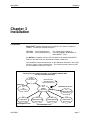
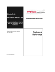
The installation creates subdirectories on the destination Hard Drive and copies
files from floppy to these subdirectories. The resulting directory structure and
the file transfers are shown in Figure 1.
Directory Structure Added & Loaded by the ORMEC INSTALL.EXE
onto the Destination Hard Drive
Existing
Root Directory
\
MotionPRO Files
WindowDOS Files
Hypertext Manual Files
Multi-Edit Files
New
\ME
Sub-Directory
New
\ORMEC\BAS
Sub-Directory
Setup Program / User Files
GN3-PRO f
MotionBASIC OIT Tool Files
New
\ORMEC
Sub-Directory
New
\ORMEC\SHELLM8
Sub-Directory
New
\ORMEC\MBTOOLS
Sub-Directory
New
\ORMEC\MMI840
Sub-Directory
New
\ORMEC\SHELL
Sub-Directory
MotionBASIC MMI Tool Files
page 5
MotionPRO
Note:
Installation
The software packages, Multi-EditTM & WindowDOSTM, as provided on ORMEC
diskettes, have been preconfigured to work in a complementary manner with the
ORMEC Software packages. The manufacturers’ original diskettes and original
documentation are also provided. The original manuals that will provide extensive
information on these software packages are:
WindowDOSTM User’s Manual by WindowDOS Associates
Multi-EditTM User’s Guide and Tutorial by American Cybernetics
Please consult these manuals for detailed information, should the need arise.
Requirements:
Your system will need to have approximately 3.0 Mbytes of disk space
available on the destination drive. This applies for all destination types
including a conventional hard disk, laptop Hard RAM or a RAM Disk.
Software Installation (See Appendix 6 for Windows installation instructions)
To start the install procedure, insert the Install Disk in a drive, and type
[f]:
INSTALL
<enter>
<enter>
where: [f] = the drive letter where the disk is inserted.
Example:
C>A:
A>INSTALL
In this example, the user’s current drive is C Drive, as is evident by the prompt.
The current drive is changed to the A Drive. The install command is then run
from the A disk drive.
After starting the install procedure, follow the prompted instructions to complete the
install procedure.
NOTE:
In addition to file transfers, the installation procedure optionally will; 1) Modify your
system’s AUTOEXEC.BAT and CONFIG.SYS files, 2) Bypass modifications, 3)
Construct an Example File.
The AUTOEXEC modification is simply the addition of the new \ORMEC directory and
the new \ME directory to your existing DOS Path. The settings for BUFFERS and
FILES in the CONFIG.SYS file are increased if necessary.
If the modification is selected by the user, it is done at the end of the installation
procedure. Along with the modification, the pre-existing AUTOEXEC.BAT is saved as a
backup file. The oldest backed-up filename will be AUTOEXEC.01, and on subsequent
modifications, the extension of a the current backup file will be the last backup
extension plus 1.
If the Example file construction is selected by the user, the example will have the
filename, AUTOEXEC.EXM.
Hardware Installation
To connect your computer’s RS-232 Communication Port to a Generation III controller,
you will need to remove the cover from the front of the controller. It is held on by
thumb screws. The RS-232 Development Port, J2, is located near the red & black
push buttons.
page 6
GN3-PRO f
MotionPRO
Installation
This development port on the Generation III controller, J2, is an asynchronous RS-232
Serial device interfaced through a 6-pin modular connector. ORMEC provides coil-cord
style cables for connection to the serial port which are compatible with IBM-AT style 9
pin connectors and with IBM-PC style 25 pin connectors.
To set up the port, press "F2" to put MotionPRO in Select Mode, then press "S" for the
SETUP MENU. Use the arrow keys to pick the desired COM port.
GN3-PRO f
page 7
MotionPRO
Installation
THIS PAGE INTENTIONALLY LEFT BLANK
page 8
GN3-PRO f
MotionPRO
Invoking MotionPRO
Chapter 4
Invoking MotionPROTM
4. Invoking MotionPROTM
The MotionPROTM environment is entered by using one of two methods. Each
method involves executing a batch file.
Method 1
This method of starting MotionPROTM uses MPRO.BAT.
MPRO.BAT performs three functions.
1) It changes the current directory to \ORMEC\BAS.
2) It loads the Hypertext manual system into memory.
3) It starts up MotionPROTM.
To start MotionPROTM, type the following command:
MPRO
<enter>
Method 2
This method of starting MotionPROTM uses MP.BAT.
MP.BAT performs one function:
1) It starts up MotionPROTM.
To start MotionPROTM, type the following command:
MP [options]
<enter>
where the options are:
/C
/M
/L
/S
/B
/O
/I
/p
/T#
=
=
=
=
=
=
=
=
=
use CGA/EGA/VGA display adapter
/c = color display
use MDA display adapter
/m = monochrome display
use LCD display adapter
/l = monochrome display
reduce "snow" on CGA display
/s = turn off /S option
use ROM Bios for display
/b = turn off /B option
enable mouse support
/o = turn off /O option
login to MotionBASIC at startup
/i = don’t login at startup
don’t scan for ports COM3 & COM4
set timeout value, where #
/t# = same as /T#
represents the new timeout value,
in the range 1055 to 214700000 milliseconds
(if no value specified, timeout = 1055)
/? = display these switch options
/h = same as /?
When either method is used, the monitor will display the startup screen for
MotionPROTM. On this screen is the software version information. This is also
displayed in the Menu Bar of the program.
GN3-PRO f
page 9
MotionPRO
Invoking MotionPRO
MotionPROTM is now in Talk Mode and is ready to communicate with a
connected Gen III Motion Controller. By default it will automatically attempt to
communicate with the Motion Controller, by performing a "Login". This "Login"
will halt any currently running program, establish communications, and
determine the MotionBASIC® version. This "Login" process can be avoided
with the /i option when invoking MotionPRO. Also, this Login at Startup, may
be configured by selecting one, of three options, 1) Always Login, 2) Never
Login, 3) Prompt the user as to whether or not a "Login" should be performed
on this particular startup.
When a cable is securely connected between the development port and a
computer comm port, and MotionPROTM has been invoked, the handshake line
will be linked and the Controller’s System Status LED labeled,
OK to Transmit, will be lit.
If this orange LED is not illuminated, check your cable connections. If you
continue to have trouble communicating, refer to the MotionBASIC® Hypertext
Manual’s chapter on Troubleshooting.
page 10
GN3-PRO f
MotionPRO
Using MotionPRO
Chapter 5
Using MotionPROTM
5. Using MotionPROTM
Using MotionPROTM
Having installed MotionPROTM on your computer and invoked its operation
there are several activities that can be performed without connecting to a
Generation III controller. However, for comprehensive operation of the
MotionPROTM Package, a serial port on the computer must be connected to
the development port of a Generation III series controller.
An important activity that can be performed, without a GEN III connected, is
user familiarization with the MotionPROTM Environment. Learning the available
options that can be performed and reviewing the on-line help that is available
would certainly be a recommended exercise. This type of introduction to the
environment can be accomplished without a Gen III controller connected to
your PC.
Other activities that could be performed without a controller connected to your
PC would constitute development work. Programs and configuration files
drafted would be saved on disk file. When the controller was connected, this
saved work could then be installed, tested, and modified.
Learning MotionPRO...
With On-Line Help
There is on-line help available for instruction on MotionPRO.
The <F1> function key calls MotionPROTM Help which is a context sensitive
Help System.
"Context Sensitive" means that depending on "where you are" on the screen
when you call for help, determines the help screen that is displayed. Related
topics can be investigated in the help system by using the cursor keys and the
<Enter> key.
With Hypertext Help
Another on-line help resource in the MotionPROTM Environment is the
Hypertext Help System provided by ORMEC. This Hypertext System is a TSR
program, Terminate and Stay Resident, which means it is always available
waiting for the "hot key" to be pressed.
The "Hot Key" to call Hypertext Help is <Alt><?> or <Alt></>.
An important concept to grasp is that Hypertext is the means to view manuals
that are stored in disk files. Therefore, the term "Hypertext" does not refer to a
GN3-PRO f
page 11
MotionPRO
Using MotionPRO
particular manual, but rather a means to read any manual in your hard disk
"library".
Modes of Operation
The MotionPROTM program operates in four fundamental modes.
(Note: there is an indicator field in the right hand bottom screen border
that indicates the current Mode.)
Talk Mode
Talk Mode enables the user to communicate directly with the Gen III CPU and
to write, edit, and execute MotionBASIC® commands, statements, and
programs. If you do not observe a Menu Bar at the top of the screen, and are
prompted with a blinking cursor, you are in Talk Mode. You must be in Talk
Mode to communicate with the GEN III.
Select Mode
Select Mode is used to access the MotionPRO Menus. It is engaged by using
the <F2> function key to call the Menu. After pressing the <F2>, key the Menu
Bar is displayed at the top of the screen. To exit Select Mode, (exit menu), and
return to Talk Mode, use the <Esc> Key.
Input Mode
Input Mode is engaged whenever the user is expected to input information from
the keyboard. This would typically be during configuration of the system when
filling out forms, and also when specifying files to be accessed for downloading,
saving, etc.
Execute Mode Execute Mode is engaged whenever MotionPROTM causes the user to wait
while it is downloading or saving files, writing configuration routines, etc.
Establishing
Communications
With MotionPROTM invoked and the computer connected to a Generation III
controller, the user can now communicate with the controller. In its default
configuration, MotionPRO automatically does a LOGIN to the Generation III
controller. This can be done manually by pressing the <F10> function key
when in TALK MODE. Login is an important step that is required so that
MotionPRO can ascertain with what version of MotionBASIC® it is
communicating. This effects specific aspects of the MP.CONFIG routine that
will be written, (see Chapter 7).
If communications are not established, the cursor will remain stationary, and
the following Error Message will print on the screen.
Cannot Send Character
Check that the cable is correct
and that the Gen-III is turned on
before continuing.
Check power, connections, or communication port assignments, to correct this
condition.
(Note: Some computers will not generate this error message due to their
inability to return a status of the serial port.)
After a powerup or a hardware reset of the controller, establishing
communications via the Login function key <F10> or by pressing the <Enter>
Key will cause the controller to print a sign-on message.
A typical sign-on message contains the following information:
Example
MotionBASIC v2.1f
Copyright (c) 1987-1993
ORMEC Systems Corp.
page 12
GN3-PRO f
MotionPRO
Using MotionPRO
60300 Bytes Free & 26624 Comment Bytes Free (80187)
Axis.List@ = {1,2}
OK
_
MENU BAR
Using the <F2> function key to call up the Menu Bar and Select Mode presents the
user with the menu bar and the pull down menus. There are several utilities and
options contained under each selection of the menu bar. The following discussion
describes each of these selections.
FILE Menu
Load Program This loads a program from a PC disk file to the Gen III CPU Program
buffer.
Save Program This command saves a MotionBASIC® program from the Gen III CPU
Program buffer to a disk file on the PC.
Merge
Program
This command merges a MotionBASIC® program from a PC disk file to
the GEN III CPU Program buffer.
Download File This command transfers a MotionBASIC® file from a PC disk file to a
Gen III Memory Disk.
Upload File
This command transfers a MotionBASIC® file from a Gen III Memory
disk to a PC disk file.
Erase File
This command deletes a MotionBASIC® file from a Gen III Memory disk
or from a PC disk file.
Format
Memory Disk
This command formats a Memory Disk. This is necessary on a new
Memory Card.
Capture
This option allows the user to open a file in which characters
communicated over the MotionPRO serial port to the user screen are
also saved to a disk file. This provides the ability to generate a
permanent record or log of MotionBASIC®/MotionPRO communications
during a session.
GEN III Menu
Configuration
This allows the user to configure the GEN III controller for the servos in
the application. Instructions for this activity are in the Chapter,
"Generation III System Configuration" in this manual.
Program Write This command displays and allows change to the current protection
Enable
level of the program buffer.
Initialize All
Memory
GN3-PRO f
Saves the current state of the Gen III unit to disk file and then
reloads all nonvolatile memory with default values.
page 13
MotionPRO
Using MotionPRO
APPLICATION Menu
This is a special menu since it can be customized by the user. The menu items that are
provided by Ormec as default are described below:
Editor
Calls the screen editor, Multi-Edit, used to edit programs and files.
OSA
Ormec Servo Analyst, provides the user with an application analysis
tool for servo motor and servo drive sizing.
WindowDOS
A file management utility used for file transfer and other useful DOS
functions.
List File /
File Print
Utilities used to examine and document any file in the
development system.
View Config/
Print Config
Utilities used to examine and document the configuration of the
servo system.
Diskcopy A→B Copy disk contents of A Drive to B Drive
Shell to DOS
A transfer to the Operating System without losing the current state of
MotionPROTM and associated programs.
SETUP Menu
Baud Rate
Choose a communication baud rate used by the PC and by the
Gen III CPU.
COM Port
Selection of the COM port on the PC to be cabled to the controller.
File Line
Numbers
Specifies whether disk program files will contain line numbers. When
checked, (on), program files must contain line numbers before loading
to the Gen III. When a program is saved, each line and its
corresponding line number from the Gen III buffer, will be saved to a
disk file. When not checked, (off), the line numbers are added during
loads to the Gen III and stripped off when programs are saved to disk
files from the Gen III Program buffer.
MotionBASIC
Version
This command selects the MotionBASIC® Version with which to work.
Quiet Speaker When checked the PC speaker will not sound a tone when a
MotionPROTM Error occurs.
Login at
Startup
This command determines the Login procedure at startup.
Default Comm This selects the default baud rate and Com Port
Save Setup
This saves the current settings of the items above. The settings are
saved to a file and are used in subsequent startups of MotionPRO.
QUIT Menu
Yes / No
page 14
Either terminate the current MotionPROTM session, or continue.
Quitting, by selecting "Yes", returns the user to the operating system.
GN3-PRO f
MotionPRO
Testing the Servo System
Chapter 6
Testing the Servo System
6. Testing the Servo System
Factory Testing
Every system is tested at ORMEC in the final cell of our manufacturing facility.
The motors are bench secured, the shafts are left free spinning, the system is
cabled, and then power is applied. A test program is loaded into the Generation
III Controller, a configuration file is established and the system is fully tested.
The tested configuration is printed and supplied with the documentation for the
system.
On-Site Testing
At the factory the test program, named SETUP.BAS, and the configuration file,
named CONFIG.BAS, are loaded into the controller’s non-volatile memory, and
remain there through shipment. Thus it is immediately available for running a
similar commissioning test at your facility, after installation and cabling of the
system.
WARNING !!!
IT IS STRONGLY RECOMMENDED THAT THE SERVO SYSTEM IS
INITIALLY TESTED WITH THE MOTOR SHAFTS MECHANICALLY
DISCONNECTED FROM ANY MACHINE OR LOAD. THIS TEST PROGRAM
IS GENERIC IN NATURE AND IS NOT INTENDED FOR USE ON
MACHINERY, BUT RATHER AS AN EXERCISER FOR THE SYSTEM’S
MOTORS.
Once communications are established between the IBM-PC and the Model 40,
type RUN <Enter> to start the SETUP program which was installed in the
controller at the factory.
The SETUP program is menu-driven and will allow you to:
1)
Home, Index and Run all the motors;
2)
Configure, observe and manipulate the Integral and Extended I/O
3)
Configure, and observe the Axis I/O
4)
Interactively adjust servo loop tuning.
5)
View and clear axis faults should they occur
This program is user friendly and menu driven. The keystrokes necessary to
perform the various operations are prompted on the screen.
GN3-PRO f
page 15
MotionPRO
Testing the Servo System
Any values that are changed during the SETUP.BAS session are only
temporarily changed since they are stored in VOLATILE DSP MEMORY.
SAVING CHANGES
To permanently save any changes that were made to the system’s loop and I/O
configuration, you must read the new values, and then write these values to
the Controller’s Non-Volatile Memory and/or to a disk file.
Step 1
To do this, utilize the Gen-III Configuration Menu in MotionPROTM.
Step 2
To read these new values,
select "Read Current Gen-III Values " from the Read Configuration Menu.
Observe:
The display will indicate that it is reading the parameters from the Gen III Unit
for each axis in the system.
You may examine these values in the various windows if you wish.
Step 3
Exit this utility by pressing the <Esc> Key.
Step 4
You will be presented with the Write Configuration Menu. This is where you
can select the destination of this write function. The recommendation is to write
to the controller by selecting "Configure Gen-III".
Observe:
The display will indicate that it is writing the parameters to the Gen III Unit for
each axis in the system.
Step 5
Optional: Saving these values to a disk file.
Repeat Steps 1, 2, & 3
Repeat Step 4 except select the
"Save to File" write destination.
Recommended File name to write is CONFIG.BAS.
Summary
Discussion
The above process reads the current configuration values, and then causes
MotionPROTM to write a new MP.CONFIG subroutine into the Setup Area of the
Non-Volatile memory of the controller.
Optionally, this MP.CONFIG subroutine should also be saved to a disk file for
permanent storage. The disk file containing this subroutine can have any name
as determined by the user, ORMEC recommends that it be named
CONFIG.BAS.
page 16
GN3-PRO f
MotionPRO
Generation III System Configuration
Chapter 7
Generation III System Configuration
7. Generation III System Configuration
System Configuration is actually a process in which MotionBASIC® code is
executed setting volatile memory variables to meaningful values. This
MotionBASIC® code that sets ORMEC Variables to particular values determines
the definition of a servo system for an application.
In an ORMEC standard approach, this set of code, consisting of Variable
assignments for each axis, is contained in a subroutine called MP.CONFIG.
Since MP.CONFIG is quite a lengthy set of code, and tedious for a user to
write from scratch, ORMEC supplies a GEN III Configuration Utility that
automatically writes the code after a user has "filled-in-the-blanks" of five
configuration "forms". These forms are pop-up windows that are selected
under the GEN-III Configuration Utility.
Initial configuration for each axis was done at the factory using this Gen-III
Configuration Menu in MotionPROTM.
In this chapter, the five configuration windows will be described, with an
example of each. Also at the end of the chapter, we will list the MP.CONFIG
subroutine code that is generated from the example data.
IMPORTANT: MotionPRO will need to have executed a LOGIN in order to ascertain for what
version of MotionBASIC® it is writing an MP.CONFIG routine. This can be done
manually by pressing the <F10> function key in TALK Mode. The version
should be diplayed in the bottom display bar of the MotionPRO screen when a
LOGIN is successful. This is done with a default setup parameter when
MotionPRO is invoked, however this feature may be disabled by the user.
The five configuration forms are:
Motor / Load Parameters Form
User Units Form
Range Variables Form
Operating Parameters Form
Servo Loop Tuning Parameters Form
GN3-PRO f
page 17
MotionPRO
Generation III System Configuration
General Instructions
The configuration forms need to be filled out for each axis in the system. Since
many applications have nearly identical setups for multiple axes, the ability to
address more than one motor during a session has been provided.
Each configuration form allows the entry of axis numbers separated by
commas. (e.g. {1,2,4} would be a set of three servos). This entire "set" of axes
can now be assigned common parameter values with single entries. If one
particular value is different for an axis, it can be configured by using the
<Pg Up> and <Pg Down> keys which scrolls through the set of axes,
individually, allowing the change of one (or more) unique parameter.
Function Key Summary
Tab
<F2>
<Pg Up>
<Pg Down>
<Enter>
Arrows
Moves between entry fields in the form
Loads the default value into a field
Scroll up through Axis Set individually
Scroll down through Axis Set individually
Scroll through choices for text fields
Move within fields (left / right) Between fields (up / down)
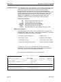
Motor/Load Parameters
This window allows you to select a motor by Model Number from one of the
standard motors listed in the system. When selected, MotionPROTM accesses a
file (MP.MTR) and obtains the following information:
1) Position Transducer Resolution
5) Motor Inertia
2) Peak Motor Torque
6) Maximum Motor Speed
3) Rated Motor Torque
7) Drive Input at Max Speed
4) Drive Input Voltage at Peak Torque
8) Absolute Encoder Feedback
In addition, you can key in a Load Inertia value for each axis if known.
MotionPROTM will then use these values to cap the speed and acceleration
limits of the system entered in the subsequent windows.
An example of this window follows, entry fields are bolded:
[ Motor/Load Parameters Form ]
Axis
1
of {1,2
}
Motor Model Number:
MAC-E002A1
Position Transducer Resolution:
6000
Motor Torque
Peak:
4.22
Drive Input at Peak Torque:
8.98
Maximum Motor Speed:
4020
Motor Inertia:
0.000068
Feedback: INCREMENTAL
cnts/rev Drive Type: TORQUE
in-lbs
Rated:
1.41 in-lbs
volts
RPM
in-lb-sec²
Load Inertia:
0.000142 in-lb-sec²
Torque Gain:
Total Machine Inertia:
Maximum Motor Acceleration:
0.470 in-lb/volt
0.000210 in-lb-sec²
3198 rev/sec²
page 18
GN3-PRO f
MotionPRO
Generation III System Configuration
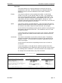
User Units
This window allows you to setup the Model 40 so that each axis can be
programmed in user units. This feature allows you to determine individual
systems of units for each axis independent of the Position Transducer
Resolution.
Position
User units for position are set by equating two numbers. On the left the
number of user units, on the right the number of counts. This establishes a
ratio to be used for position conversion. In the example window below, 360
user units are equated to 6000 counts ( which happens to be 1 rev). As you
might deduce, this user is working in whole degrees , 360 per rev. (This
conversion ratio would have been maintained in the same way if on the left was
entered 6 user units equated to 100 counts.)
Speed
User units for speed is set slightly differently. First on the right side, enter the
absolute maximum speed limit you wish to establish for that axis in RPM. You
will be able to set another "range limit" below this value, but not higher.
On the left side of the equation for speed, enter the number of user speed units
that equate to this maximum RPM value. This establishes a ratio to be used
for speed conversion.
In the window below, the speed limit is left at the motor maximum, 4020 RPM,
and user units are also in RPM, and thus 4020 is also on the left side of the
equation.
User Units for acceleration are set similar to those of speed. The absolute
maximum acceleration that will be allowed is entered on the right side of the
equation in rev/sec2. You will be able to set another "range limit" below this
value, but not higher.
Acceleration
On the left side is entered the corresponding maximum user unit value for
acceleration.
In the window below, on the right side, the maximum remains at the motor
maximum established for the inertial load, and on the left side we have entered
the matching value in radians/sec2, since that is desired in this example case.
An example of this window follows, entry fields are bolded:
[ User Units Form ]
Axis
1
of {1,2
Position Transducer Resolution
Conversion Factor / Limit
Axis Position
Pacer Position
Machine/Axis Speed Limit
Pacer Transducer Speed Limit
Machine/Motor Accel Limit
Time (all axes)
Gear Speed Multipliers
GN3-PRO f
}
Axis:
6000
User Units
360 degrees
360 degrees
4020 RPM
Pacer:
6000 cnts/rev
=
Motor Units
=
=
=
6000
6000
4020
4000
3193
1
20061 rad/sec/sec =
1 msec
=
Output:
1
Input:
counts
counts
RPM
RPM
rev/sec²
msec
1
page 19
MotionPRO
Generation III System Configuration
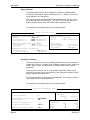
Range Variables
This window allows you to set the "application maximum" allowable speed,
acceleration, deceleration, torque, and position error. In addition, you can set
up the maximum In-Position Error.
The values for Speed and Acceleration and Deceleration can only be as high
as the left side of the user units form. The value for Torque can only be as
high as the peak torque value in the Motor/Load Parameters Form.
An example of this window follows, entry fields are bolded:
[ Range Variables Form ]
Axis
1
of {1,2
}
Maximum Allowable Machine Parameters:
Speed:
3600 RPM
Acceleration:
12000 rad/sec/sec
Deceleration:
12000 rad/sec/sec
Machine Limits:
Speed:
4020 RPM
Accel:
20061 rad/sec/sec
Maximum Allowable Motor Parameters:
Drive Output:
4.22 in-lbs
DRV.MAX@:
29423 ( 8.98 volts)
Motor Limits:
Peak Torque:
Rated Torque:
Max Speed:
4.22 in-lbs
1.41 in-lbs
4020 RPM
Maximum Controller Parameters:
Position Error:
360 degrees
In-Position Error:
2 degrees
Operating Parameters
This window allows you to set up operating parameters such as the direction of
rotation of the motor for "forward" travel, a Modulo Position Counter, a choice of
position data to output, and the type of acceleration profile used in MOVE
statements.
Limits are also set from this form. The software forward and reverse travel
limits can be set from this form as well as the low and high trip points for three
position triggered outputs per axis.
Also the deceleration rate used when a MotionBASIC® error causes a motor to
stop is also set in this configuration form.
An example of this window follows, entry fields are bolded:
[ Operating Parameters Form ]
Axis
1
of {1,2
}
Forward Rotation Direction:
COUNTER-CLOCKWISE
Position Modulo:
0
MotionDATA Output Source:
Pacer Input:
PASS-THRU
ON
S-Curve Distribution:
0%
Loop Rate (all axes):
3000 Hz
Error Deceleration Rate:
1000
page 20
Software Travel Limits:
(degrees)
Forward
0
Reverse
0
Electronic Limit Switch Ranges:
(degrees)
Low
High
ELS1:
0
0
ELS2:
0
0
ELS3:
0
0
GN3-PRO f
MotionPRO
Generation III System Configuration
Tuning Parameters
This window allows you to set the servo gains. These parameters include both
Torque Gain and Inertia for the servodrive and motor, which are initialized in
the Motor/Load Parameters window. It also allows setting the Velocity Loop
Time Constant as well as Kvi, Kp, Kpi, Kaf, and Kvf.
An example of this window follows, entry fields are bolded:
[ Servo Loop Tuning Parameters Form ]
Axis
1
of {1,2
}
Drive Type:
Torque Gain:
Load Inertia at Motor Shaft:
Total Machine Inertia:
Torque
0.470 in-lb/volt
0.000142 in-lb-sec²
0.000210 in-lb-sec²
Velocity Loop Time Constant:
Kvi
Kp
Kpi
Kaf
Kvf
Velocity Integral Factor:
Position Gain Factor:
Position Integral Factor:
Acceleration Feedforward Factor:
Velocity Feedforward Factor:
3.00 msec
100%
100%
0%
0%
100%
MP.CONFIG SUBROUTINE GENERATION
Having filled out these forms for each axis in your system, your are able to
generate the MP.CONFIG routine.
Again, this routine consists of variable assignment statements only. The
routine’s program lines set ORMEC Variables to the values that you have
keyed-in on the configuration forms.
MP.CONFIG can be written to some destination when you exit from the GEN-III
Configuration Activity. You have choices as to where this code is written. You
may select to write the MP.CONFIG subroutine to the GEN-III Controller’s NonVolatile Program Buffer, or you may write it to a disk file, where you specify the
name of the file.
NOTE:
GN3-PRO f
Only when this subroutine is executed, do these Volatile DSP
Memory Variables actually take on the values specified in these
lines of code. After the Configuration Utility constructs
MP.CONFIG it does execute the routine. Otherwise, a direct
command such as GOSUB MP.CONFIG would need to be issued
to execute this routine and set the variables to the values entered.
page 21
MotionPRO
Generation III System Configuration
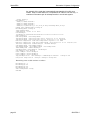
An example of the code that is automatically generated by this utility now
follows. Keep in mind that this is a complete set of code for one axis only. It
continues in the same style for subsequent axis in a multi-axis system.
’!AUTO 65000,1
MP.CONFIG:
’!MTR(1)="MAC-E002A1"
’!MTR(2)="MAC-E002A1"
’!MTR(3)="MAC-E002A1"
’!MTR(4)="(unknown)",1.41,4.22,8.98,0.000068,4020,8.04,1
EVENT OFF :MODE@(AXIS.LIST@)=0
MD.MODE@(AXIS.LIST@)=0
LOOP.RATE@=3000
TIME.MUL@=1 ’Time is in msec
EIO.MODE@=0
IO.MODE@(1)="ROFOIOIOIOIOIOIOIIIIIIIIIIIIIIIIIIIIIIII"
AXIS.SET@={1}
CNT.REV@=6000 :PCT.REV@=6000
POS.MUL@=6000 :POS.DIV@=360 ’Axis Position is in degrees
PPS.MUL@=6000 :PPS.DIV@=360 ’Pacer Position is in degrees
MTR.SPD.LIM@=4020 :USR.SPD.LIM@=4020 ’Speed is in RPM
MTR.ACL.LIM@=3193 :USR.ACL.LIM@=20061 ’Acceleration is in rad/sec/sec
PCR.SPD.LIM@=4000 :INSPD.MUL@=1 :OUTSPD.MUL@=1
SPD.MAX@=3600 :DRV.MAX@=29424
ACL.MAX@=18000 :DCL.MAX@=18000 :DCL.ERR@=1000
PERR.MAX@=360 :PERR.INPOS@=2
CW.FWD@=TRUE :POS.MOD@=0 :SCURVE@=0
STL.FWD@=0 :STL.REV@=0
ELS1.LOW@=0 :ELS1.HIGH@=0
ELS2.LOW@=0 :ELS2.HIGH@=0
ELS3.LOW@=0 :ELS3.HIGH@=0
TRQ.GAIN@=0.470! :VEL.GAIN@=0 :INERTIA@=0.000210! :VLTC@=2.20!
KVI@=100 :KP@=100.0! :KPI@=0 :KAF@=0 :KVF@=100
Remaining axes would continue as above
MD.MODE@(1)= 1
MD.MODE@(2)=10
MD.MODE@(3)=10
MD.MODE@(4)=10
AXIS.SET@=AXIS.LIST@
RETURN
page 22
GN3-PRO f
MotionPRO
Final System Configuration
Chapter 8
Final System Configuration
8. Final System Configuration
When initial configuration was done at the factory, the Servo Gains were for the
selected motors with no load inertia attached. For optimal performance, and
certainly if the load inertia for an axis is much greater than the inertia of the
selected servomotor, each servo system should have its Servo Loop Tuning
Parameters adjusted after it is connected to the load.
WARNING !!!
THESE INSTRUCTIONS ASSUME THAT YOU NOW HAVE EXPERIENCE WITH
THE SETUP.BAS PROGRAM AND HAVE ALREADY TESTED YOUR SERVO
MOTORS WHILE THE MOTORS WERE DISCONNECTED FROM THEIR
APPLICATION LOADS.
DO NOT CONTINUE UNLESS YOU HAVE
PREVIOUSLY TESTED THE UNCOUPLED MOTORS WITH THIS PROGRAM.
Couple the motor shafts to the machine loads.
Execute the SETUP.BAS program ( with associated MP.CONFIG subroutine).
Of course these programs must be loaded into the controller if they are not
already in Non-Volatile Memory.
With the program loaded into the controller, type RUN and press the Enter key
to start the SETUP program again and perform the following steps for each axis
in the system:
a)
Key in the appropriate value for total inertia (INERTIA@), including both
motor and load. If load inertia is not known, optionally fine tune the
system by adjusting the value for INERTIA@ empirically.
This may be done by accessing the Tuning Menu, setting the Axis
Mode to Velocity, and setting VLTC@ between 8 and 30 ms. Execute
Indexes that do not cause the system to "torque limit". Observe the
velocity errors reported at the bottom of the screen and adjust
INERTIA@ until the first few errors immediately following the index
average close to 0.
GN3-PRO f
page 23
MotionPRO
Final System Configuration
b)
Set the Axis Mode to Position and adjust VLTC@ to the lowest
acceptable value. Cause indexes to occur, and observe both the
position error and the audible noise. If you have a scope, observe both
the torque and velocity responses. The velocity response should have
minimal overshoot, but the torque response may overshoot
considerably. The torque response should not, however, "ring"
excessively.
c)
Adjust the position loop integral gain (KPI@) to 100% in applications
where position error during motion is critical, such as electronic gearing
or in the control of continuous web systems.
d)
The other gains in the system should be adjusted only to meet critical
and unusual performance criteria by a qualified servo technician or
engineer. ORMEC provides a training class which covers these
procedures and the theory behind them in detail.
Also, you will want to use the Gen-III Configuration Menu described in the last
section to configure your Model 40 for your particular application. Simply "pulldown" that Menu and fill out the pop-up windows with the appropriate
information for each of the axes in your system.
When the system is configured for your application, you should proceed to
develop your application. MotionPROTM includes a number of application
software development tools called MotionBASIC® Tools. These programs and
documentation are designed to make applications program development much
easier by providing working program modules for accomplishing functions
common to most motion control applications, such as an Error Handler and an
I/O Menu. The training class provides instruction in the use of these tools. We
trust that they will prove useful in helping you get started with Generation III.
page 24
GN3-PRO f
MotionPRO
Appendix 1
Appendix 1
MotionPROTM Information
A1 MotionPROTM Information
This appendix section contains information on the files and environment
variables used with MotionPROTM. It is intended for experienced
DOS users.
The following files are needed by MotionPROTM:
MPRO.BAT
MP.BAT
MP1.EXE
MP.HLP
MP.APP
MP.CFG
MP.MTR
Startup Command for MotionPROTM
Used to execute MotionPROTM with large applications.
MotionPROTM executable program.
Help database used by MotionPROTM when F1 is pressed.
List of applications programs used with MotionPROTM.
Optional MotionPROTM custom configuration file.
ORMEC motors parameter file.
These files are described below in greater detail, so that the experienced user
may fully understand their use.
MPRO.BAT File
This file performs three useful functions for the user. It changes the current
directory to \ORMEC\BAS, it then loads the Hypertext System into memory, and
then it starts MotionPROTM. Users that prefer a different starting directory
should edit this file.
This file must be located in one of the directories specified by the DOS "PATH"
environment variable, or the current directory.
MP.BAT File
This file starts MotionPROTM. It is required in order that MotionPROTM can be
unloaded from memory during a call of a large application program from within
MotionPROTM (see MP.APP).
This file must be located in one of the directories specified by the DOS "PATH"
environment variable or the current directory.
GN3-PRO f
page 25
MotionPRO
Appendix 1
Several options can be typed with this command. These options are available
to startup MotionPROTM for your type of system configuration. These options
are as follows:
options:
/C
/M
/L
/S
/B
/O
/I
/p
/T#
=
=
=
=
=
=
=
=
=
use CGA/EGA/VGA display adapter
/c = color display
use MDA display adapter
/m = monochrome display
use LCD display adapter
/l = monochrome display
reduce "snow" on CGA display
/s = turn off /S option
use ROM Bios for display
/b = turn off /B option
enable mouse support
/o = turn off /O option
login to MotionBASIC at startup
/i = don’t login at startup
don’t scan for ports COM3 & COM4
set timeout value, where #
/t# = same as /T#
represents the new timeout value,
in the range 1055 to 214700000 milliseconds
(if no value specified, timeout = 1055)
/? = display these switch options
/h = same as /?
MP1.EXE File
This is the main MotionPROTM executable program. It is invoked by the
MP.BAT file.
MP.HLP File
This is the database used by MotionPROTM to obtain Help when the F1 key is
pressed. This file must be located in the directory specified by the DOS
environment variable "MPPATH". If "MPPATH" is not defined, MP.HLP must be
located in the same directory as MP1.EXE.
MP.APP File
This file contains the list of application programs which appear in the
MotionPROTM Application menu. It can be customized by the user to include
applications which are frequently used from within MotionPROTM. A description
of the file format is included as a comment at the beginning of the file, which
can be edited with an ordinary text editor.
MotionPROTM searches for this file in up to three directories as follows:
1)
the current working directory,
2)
the directory and file name specified by the DOS environment variable
"MPAPP",
3)
the directory specified by the DOS environment variable "MPPATH", or
the directory containing MP1.EXE.
MP.CFG File
This optional file allows the user to customize the initial configuration of
MotionPROTM. This includes the initial COM port, baud rate, and setup options.
This file is created by the "Save Setup" command, executed from the Setup
Menu of MotionPROTM.
MotionPROTM searches for this file in up to three directories as follows:
1)
the current working directory,
2)
the directory and file name specified by the DOS environment variable
"MPCFG",
3)
the directory specified by the DOS environment variable "MPPATH", or
the directory containing MP1.EXE.
MP.MTR File
This is the database used by MotionPROTM to supply the model numbers and
specifications for all ORMEC motors. It is used by the Axis Setup forms.
This file must be located in the directory specified by the DOS environment
variable "MPPATH". If "MPPATH" is not defined, MP.MTR must be located in
the same directory as MP1.EXE.
page 26
GN3-PRO f
MotionPRO
MotionPROTM
Environment
Variables
Appendix 1
MotionPROTM uses several DOS environment variables to locate various files
it needs. All of these environment variables are optional, but some may be
needed in certain configurations. Below is a detailed description of these
variables.
MPPATH Environment Variable
This environment variable should be defined when MotionPROTM is used under
version 2.x of DOS, or when MP1.EXE is not located in the DOS PATH. It
contains the full directory path where the MotionPROTM files are located.
MP1.EXE uses this environment variable to find MP.HLP, MP.APP, MP.CFG,
and MP.MTR. If not defined, MotionPROTM looks in the same directory as
MP1.EXE under DOS 3.0 or later, or the current working directory under DOS
2.x.
Example: SET MPPATH=C:\ORMEC
MPAPP Environment Variable
This optional environment variable allows the user to define a
custom MP.APP file for a specific environment. It contains the
full path AND file name of the custom applications file.
Example: SET MPAPP=C:\ORMEC\MP.APP
MPCFG Environment Variable
This optional environment variable allows the user to define a
custom MP.CFG file for a specific environment. It contains the
full path AND file name of the custom configuration file.
Example: SET MPCFG=C:\ORMEC\MP.CFG
MPTMP, TEMP and TMP Environment Variables
These optional environment variables allows the user to specify where
temporary files are to be stored. MotionPROTM creates a temporary file called
MP.$$$ when it unloads itself during execution of an application program. This
file is normally stored in the current working directory. If it is not desirable for
MotionPROTM to create a temporary file in the current working directory, the
environment variable "MPTMP", "TEMP", or "TMP" may be defined to contain
the path of the directory where this temporary file is to be stored. (MPTMP
takes precedence over TEMP, which takes precedence over TMP)
GN3-PRO f
Example 1: SET MPTMP=E:
(current directory of drive E)
Example 2: SET TEMP=D:\
(root directory of drive D:)
Example 3: SET TMP=F:\TEMP
(\TEMP directory of drive F:)
page 27
MotionPRO
Appendix 1
THIS PAGE INTENTIONALLY LEFT BLANK
page 28
GN3-PRO f
MotionPRO
Appendix 2
Appendix 2
Customizing MotionPROTM
A2 Customizing MotionPROTM
This appendix section contains information on the setup of MotionPROTM
includes some options that the user may wish to change. If the user wishes to
retain these configuration changes for subsequent startups of MotionPROTM this
can be done quite easily. The Setup Menu of MotionPROTM provides the
means to change configuration options and to save this new configuration.
The items that can be changed from the setup menu are covered in the
Chapter "Using MotionPRO".
Another routine customization that a user may want to perform is the alteration
of the MP.APP file for MotionPROTM. This file effects the Application Menu in
MotionPROTM. It determines which applications are available, the text
presentation in that menu and by what commands the different applications are
called when they are selected. Other considerations have to do with system
memory. One of the options that can be used in the MP.APP file forces
MotionPROTM to exit from memory while the selected application is being run.
As provided from ORMEC the Application Menu allows the user to call the
Multi-EditTM screen editor, and to run the Ormec Servo Analyst program, to
startup and use Window DOS, to print and view configuration files.
GN3-PRO f
page 29
MotionPRO
Appendix 2
The following text is also provided as comments within the MP.APP file. This allows the user to edit
the file while also having the instructions in that very same file.
Syntax of MP.APP file entries:
<menu item>[, <hot key>]
[@][>]<command> <arg list>
where:
<menu item> Menu item text that will appear on applications menu. This must begin in
column 1.
<hot key>
A single letter from <menu item> that will select the item when pressed
(usually the first letter).
[@]
Optional prefix which causes MotionPROTM to be unloaded from memory
before this application is executed. Only has effect when MotionPROTM is
invoked from the "MP.BAT" file. Must not begin in column 1.
[>]
Optional prefix which causes MotionPROTM to execute this application
from a secondary copy of the command processor. This allows
<command> to be a batch (".BAT") file. Must not begin in column 1.
<command>
Name of the program to be executed. Program must be a ".EXE" or a
".COM" file, or a ".BAT" file if the ">" prefix is used. The DOS PATH will
be searched if no path is specified. Must not begin in column 1.
<arg list>
List of command line arguments, separated by spaces. A special
argument of the form "<f text>" will prompt the user for a file name with a
text message, and then replace itself with the file name.
The following lines are in the MP.APP File as provided by ORMEC.
Edit F5, E
@me <f Enter name of file to edit:>
OSA, O
osa
Window DOS, W
>wd35 -x
List File, L
>mplist <f Enter name of file to list:>
File Print, F
cprint -m4 -w84 -l55 <f Enter name of file to print:>
View MP.CONFIG, V
printcfg <f Enter name of configuration file to view:> /p /w
Print MP.CONFIG, P
printcfg <f Enter name of configuration file to print:> lpt1 /m6 /w
Diskcopy A = B, D
diskcopy a: b:
Customization is achieved with a text editor and by adding, deleting, or altering entries in this file.
The changes can be easily tested by starting MotionPROTM and selecting the edited entries via the
Application Menu.
page 30
GN3-PRO f
MotionPRO
Appendix 3
Appendix 3
Hypertext Help Information
A3 Hypertext Help
Hypertext is an information system which attempts to more closely parallel the
human mind’s thought process than does traditional information sources, such
as bound manuals or flat text files. Hypertext produces this effect through a
network of "nodes" each of which contain data on a topic, but is linked to and
can be accessed via other, related items within the network.
Two file types are included with the Ormec Hypertext System. The executable
file which loads the system, and reference files which constitute the manuals for
MotionBASIC®, Hypertext Help, and Revision Information.
The specific files are:
ORMEC.EXE
This file loads the hypertext system into memory making it
available to be called from other programs. Pressing Alt ? will
call up a memory resident Hypertext System.
HYPERTXT.HYP
This file is on the Ormec Hypertext Manual System itself. It
also introduces concepts and familiarizes the user with Ormec
Motion Controllers.
MB.HYP
This file is on the programming language MotionBASIC®. This
is the reference that is easily consulted while using
MotionPROTM to program the Gen III controllers.
MBREVS.HYP A file that will document upgrades and changes to the language
and the related manuals.
MBTOOLS.HYP
A file that will document the use of the OIT MotionBASIC®
Tools package and its use in developing an OIT application
solution.
MMITOOLS.HYP A file that will document the use of the MMI MotionBASIC®
Tools package and its use in developing an MMI DIsplay
application solution.
GN3-PRO f
page 31
MotionPRO
Appendix 3
Starting Hypertext
The following command is entered to load the Hypertext System.
ORMEC [hypfile] [options]
hypfile: Path and name of the hypertext database file to use (default extension
".HYP"), or directory in which the database files are located. If not
specified, the file "HYPERTEXT.HYP" in the executable directory is
used.
options:
/C = use CGA/EGA/VGA adapter
/M = use MDA display adapter
/L = use LCD display adapter
/S = reduce "snow" on CGA display
/B = use ROM BIOS for display
/O = enable mouse support
/X = invoke from the command line
/? = display this usage message
Example:
/c = color display
/m = monochrome display
/l = monochrome display
/h = same as /?
Showing user entry and the system’s response. In this
example the user is starting the Hypertext System with the
option to enable mouse operation support.
C>ORMEC
ORMEC /O
<enter>
ORMEC Hypertext Help, Version 1.2f
Copyright (c) 1992, ORMEC Systems Corporation, All Rights Reserved
ORMEC Hypertext Help has been loaded.
Press Alt-? to invoke HELP.
C>
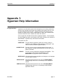
HYPERTEXT KEYS
The special keys that can be used when in the Hypertext System are listed
below:
F1 = INDEX
Displays the current manual’s Index.
F2 = MENU
Display/select available manuals from the hard disk
F3 = SEARCH
Search for a string, word, topic, phrase, link etc...
F4 = AGAIN
Continue the last search for another occurrence
F10 = EXIT
Special EXIT, it leaves a bookmark for the next access
<Pg Up>
Move to preceding page in a chapter
<Pg Dn>
Move to next page in a chapter
<Backspace>
Go back to the previous chapter you accessed last
<Ctrl> <Backspace>
page 32
Go to the "parent" chapter of the current chapter
<Esc>
Normal EXIT, returns you to your previous activity
Arrow Keys
Move the cursor between link topics
<Enter>
Go to cursor selected topic, or perform cursor selected
function
GN3-PRO f
MotionPRO
Appendix 4
Appendix 4
WindowDOSTM Information
A4 WindowDOSTM Information
WindowDOSTM is provided on Ormec software disks with the file WD3.EXE.
This is the main executable file of WindowDOSTM. Ormec also provides the
original diskettes and documentation for WindowDOSTM. For users who intend
to further customize and reconfigure the setup of WindowDOSTM as supplied by
Ormec, they should refer to the manufacturer’s documentation and
reconfigurration utilities. This appendix will list some basic information on
WindowDOSTM, for detailed instructions please refer to the original manual.
To run WindowDOSTM from MotionPRO, select the WindowDOSTM menu entry
from the application pull down menu. (is called in MP.APP by WD3 -X)
To run WindowDOSTM from DOS type:
WD3 [option]
where [option] can be any number of the following single characters, they must
be separated by a space character or a forward slash.
A
B
C
D
E
F
G
H
J
K
M
N
P
Q
R
S
T
U
W
X
Z
GN3-PRO f
Sort the directories in ascending order. (DEFAULT)
Set colors to Black & White
Sort by creation date
Sort the directories in descending order.
Sort by extension
Sort directories by filename (DEFAULT)
Set for unusual EGA display cards.
Set for Hercules Display card.
Display directory names with leading \.
Alternate Hotkey.
set for mute mode
Do not sort. Order as found on disk.
Turn on pop up password.
Turn on quick entry.
Turn on display root on call up.
Sort according to size
Turn on screen timeout
Uninstall WindowDOSTM
Switch Function & Shift Function Keys
Run in execute only mode. ( not memory resident)
Set for superior CGA cards.
page 33
MotionPRO
Appendix 4
THIS PAGE INTENTIONALLY LEFT BLANK
page 34
GN3-PRO f
MotionPRO
Appendix 5
Appendix 5
Multi-EditTM Information
A5 Multi-EditTM Information
Multi-EditTM is provided on Ormec software disks. Ormec also provides the
original diskettes and documentation for Multi-EditTM. For users who intend to
further customize and reconfigure the setup of Multi-EditTM as supplied by
Ormec, they should refer to the manufacturer’s documentation and setup
utilities. This appendix will list some basic information on Multi-EditTM, for
detailed instructions please refer to the original manual.
To run Multi-EditTM from MotionPRO, select the Edit selection from the
application pull down menu. (is called in MP.APP by mec.bat)
To run Multi-EditTM from DOS type:
ME [filename]
The filename is optional. Use it if you want to load the file on startup.
GN3-PRO f
HELP
The <F1> key will bring up context sensitive on-line help at any
point within Multi-Edit.
MAIN MENU
The <F2> key will access the main menu. Most operations are
selected from the menu.
FUNCTION
KEYS
The operations assigned to each of the function keys are
are labeled at the bottom of the screen. Notice that these
selections change when you hold the Alt, Shift, or Ctrl Keys.
UNDO/REDO
Multi-Edit supports full Undo of any editing operation that
changes text or makes major changes to the cursor position.
QUITTING
MULTI-EDIT
From a menu: the <ESC> key will back you out of any menu.
While editing a file: the <F2> key will access the main menu
where you can select the "Quit" option.
page 35
MotionPRO
Appendix 5
THIS PAGE INTENTIONALLY LEFT BLANK
page 36
GN3-PRO f
MotionPRO
Appendix 6
Appendix 6
WindowsTM Information
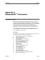
A6 WindowsTM Information
This appendix section contains information on the files used with MotionPROTM
in a WindowsTM environment. It is intended for experienced WindowsTM users.
The following files are needed by MotionPROTM:
MP.PIF
MP.ICO
MBHYP.PIF
MBHYP.ICO
Program Information File for MotionPROTM
Icon for MotionPROTM.
Program Information File for ORMEC Hypertext Help
Icon for ORMEC Hypertext Help.
These files are described below in greater detail, so that the experienced user
may fully understand their use.
MP.PIF File
This file changes the Start-up directory to C:\ and runs the batch file
C:\ORMEC\MPRO.BAT, with 343KB of memory required. Users that prefer a
different starting directory should edit a copy of this file.
MP.ICO File
This file contains the graphical icon for the MotionPROTM program item. Users
that prefer a different icon should edit a copy of this file.
MBHYP.PIF File
This file changes the Start-up directory to C:\ORMEC and runs
C:\ORMEC\ORMEC.EXE with "/c /O /x C:\ORMEC\MB.HYP" as Optional
Parameters and 160KB of memory required. Users that prefer a different
starting directory and/or options should edit a copy of this file.
MBHYP.ICO File
This file contains the graphical icon for the ORMEC Hypertext Help program
item. Users that prefer a different icon should edit a copy of this file.
GN3-PRO f
page 37
MotionPRO
Appendix 6
Creating
WindowsTM
Items
To run MotionPROTM from WindowsTM with the new PIF and icon, create a new
item with \ORMEC\MP.PIF as the command line property and \ORMEC\MP.ICO
as the icon.
To run Hypertext from WindowsTM with the new PIF and icon create a new item
with \ORMEC\MBHYP.PIF as the command line property and
\ORMEC\MBHYP.ICO as the icon.
Memory Limitations
This version of MotionPROTM has higher memory requirements than the
previous versions. In some cases, while running MotionPROTM under
WindowsTM, there may not be enough memory left to execute WindowDOSTM. If
you have this problem, we suggest using Windows File Manager instead
of WindowDOSTM.
Communications
Hints
Windows allows MotionPROTM to execute independently in several windows
which allows the possibility of each MotionPROTM window to use the same
COM port. This could result in communication problems. To prevent this
from occuring, it is recommended that the 386 Enhanced option in the
Windows Control Panel be set to Always Warn for each COM port. After
that, Windows will warn you if several MotionPROTM programs try to
access the same communication port.
MotionPROTM has been changed to better co-exist in the WindowsTM
Environment. This allows background processing for other tasks to
occur, but there is also a chance that while executing a number of
other programs under WindowsTM that you could experience communication
problems. This is something that happens very rarely in normal
execution, but is possible when WindowsTM becomes too busy to handle
MotionPRO communications in a timely fashion. If you experience a
communication problem, shut down any unnecessary programs, or run
MotionPROTM from DOS.
page 38
GN3-PRO f