1
TSX ESY 007 Module
Installation Manual
35010594 02
October 2005 eng
2
35010594 02 October 2005
Table of Contents
Safety Information . . . . . . . . . . . . . . . . . . . . . . . . . . . . . . . . . . . . 7
About the Book . . . . . . . . . . . . . . . . . . . . . . . . . . . . . . . . . . . . . . . 9
Part I The TSX ESY 007 Module . . . . . . . . . . . . . . . . . . . . . . . . 11
At a Glance . . . . . . . . . . . . . . . . . . . . . . . . . . . . . . . . . . . . . . . . . . . . . . . . . . . . . 11
Chapter 1
General Presentation of the TSX ESY 007 Module . . . . . . . . . 13
At a glance . . . . . . . . . . . . . . . . . . . . . . . . . . . . . . . . . . . . . . . . . . . . . . . . . . . . .
At a Glance . . . . . . . . . . . . . . . . . . . . . . . . . . . . . . . . . . . . . . . . . . . . . . . . . . . . .
Note concerning the input/output extension bus . . . . . . . . . . . . . . . . . . . . . . . . .
Panorama of the Series 7 products in the Schneider catalog . . . . . . . . . . . . . . .
Main components - Presentation. . . . . . . . . . . . . . . . . . . . . . . . . . . . . . . . . . . . .
Figure showing sample topology of input/output extension bus . . . . . . . . . . . . .
Main features of input/output extension bus . . . . . . . . . . . . . . . . . . . . . . . . . . . .
13
14
15
16
17
20
21
Part II Hardware Installation of TSX ESY 007 Input/Output
Extension Bus Interface Coupler . . . . . . . . . . . . . . . . . . 23
At a Glance . . . . . . . . . . . . . . . . . . . . . . . . . . . . . . . . . . . . . . . . . . . . . . . . . . . . . 23
Chapter 2
2.1
2.2
35010594 02 October 2005
Input/Output Extension Bus Coupler Interface:
TSX ESY 007 . . . . . . . . . . . . . . . . . . . . . . . . . . . . . . . . . . . . . . . 25
At a Glance . . . . . . . . . . . . . . . . . . . . . . . . . . . . . . . . . . . . . . . . . . . . . . . . . . . . .
Description of the TSX ESY CM 007 Module . . . . . . . . . . . . . . . . . . . . . . . . . . .
At a Glance . . . . . . . . . . . . . . . . . . . . . . . . . . . . . . . . . . . . . . . . . . . . . . . . . . . . .
Physical presentation . . . . . . . . . . . . . . . . . . . . . . . . . . . . . . . . . . . . . . . . . . . . .
Mounting/Installation . . . . . . . . . . . . . . . . . . . . . . . . . . . . . . . . . . . . . . . . . . . . . .
Connections . . . . . . . . . . . . . . . . . . . . . . . . . . . . . . . . . . . . . . . . . . . . . . . . . . . .
LED module status indicators . . . . . . . . . . . . . . . . . . . . . . . . . . . . . . . . . . . . . . .
Special LED indicators of the TSX ESY 007 Module . . . . . . . . . . . . . . . . . . . . .
Technical Features . . . . . . . . . . . . . . . . . . . . . . . . . . . . . . . . . . . . . . . . . . . . . . .
User safety . . . . . . . . . . . . . . . . . . . . . . . . . . . . . . . . . . . . . . . . . . . . . . . . . . . . .
Use of the TSX ESY 007 Module for System Upgrade . . . . . . . . . . . . . . . . . . . .
At a Glance . . . . . . . . . . . . . . . . . . . . . . . . . . . . . . . . . . . . . . . . . . . . . . . . . . . . .
25
26
26
27
28
30
32
33
34
36
37
37
3
2.3
2.4
2.5
At a Glance . . . . . . . . . . . . . . . . . . . . . . . . . . . . . . . . . . . . . . . . . . . . . . . . . . . . . 38
Installation . . . . . . . . . . . . . . . . . . . . . . . . . . . . . . . . . . . . . . . . . . . . . . . . . . . . . . 39
Recovering racks 0 to 3 . . . . . . . . . . . . . . . . . . . . . . . . . . . . . . . . . . . . . . . . . . . . 42
For double format racks . . . . . . . . . . . . . . . . . . . . . . . . . . . . . . . . . . . . . . . . . . . . 44
LES120/LFS120 Remote Entrance Links . . . . . . . . . . . . . . . . . . . . . . . . . . . . . . 45
Methodology for Upgrading the PL7-3 PLC Program . . . . . . . . . . . . . . . . . . . . . 47
Input/Output Extension Bus Diagnostics . . . . . . . . . . . . . . . . . . . . . . . . . . . . . . . 50
I/O extension bus diagnostics - Presentation. . . . . . . . . . . . . . . . . . . . . . . . . . . . 50
Operating Modes of the TSX ESY CM 007 Module. . . . . . . . . . . . . . . . . . . . . . . 51
TSX ESY 007 Module Operating Modes . . . . . . . . . . . . . . . . . . . . . . . . . . . . . . . 51
Precautions for Use . . . . . . . . . . . . . . . . . . . . . . . . . . . . . . . . . . . . . . . . . . . . . . . 53
Double rack addressing . . . . . . . . . . . . . . . . . . . . . . . . . . . . . . . . . . . . . . . . . . . . 53
Part III Software Installation for the TSX ESY 007 Module. . . . . 55
At a Glance . . . . . . . . . . . . . . . . . . . . . . . . . . . . . . . . . . . . . . . . . . . . . . . . . . . . . 55
Chapter 3
TSX ESY 007 Module Software Installation - Principles. . . . . 57
At a Glance . . . . . . . . . . . . . . . . . . . . . . . . . . . . . . . . . . . . . . . . . . . . . . . . . . . . . 57
Installation of the I/O extension bus - Presentation . . . . . . . . . . . . . . . . . . . . . . . 58
TSX ESY 007 Module Architecture . . . . . . . . . . . . . . . . . . . . . . . . . . . . . . . . . . . 60
Structure of a Series 7 module . . . . . . . . . . . . . . . . . . . . . . . . . . . . . . . . . . . . . . 61
Addressing Language Objects Associated with Series 7 Devices On the I/O
Extension Bus . . . . . . . . . . . . . . . . . . . . . . . . . . . . . . . . . . . . . . . . . . . . . . . . . . . 63
Use of EF SEND_REQ for Handling Series 7 Modules with Extended and
Message Registers . . . . . . . . . . . . . . . . . . . . . . . . . . . . . . . . . . . . . . . . . . . . . . 65
Chapter 4
Configuring the TSX ESY 007 Module . . . . . . . . . . . . . . . . . . . 75
At a Glance . . . . . . . . . . . . . . . . . . . . . . . . . . . . . . . . . . . . . . . . . . . . . . . . . . . . . 75
Declaring a TSX ESY 007 Module in the PLC rack . . . . . . . . . . . . . . . . . . . . . . . 76
Description of the Configuration Screen of a TSX ESY 007 Module . . . . . . . . . . 77
Declaring a Series 7 Device to the TSX ESY 007 Module. . . . . . . . . . . . . . . . . . 79
Displaying the I/O Extension Bus in the Project Browser . . . . . . . . . . . . . . . . . . 82
Modifying the software configuration of a TSX ESY 007 Module . . . . . . . . . . . . 84
Accessing the Description of a Series 7 Module . . . . . . . . . . . . . . . . . . . . . . . . . 85
Accessing the Description of a Series 7 Rack. . . . . . . . . . . . . . . . . . . . . . . . . . . 86
Accessing the Description of a Series 7 Module . . . . . . . . . . . . . . . . . . . . . . . . . 87
Modifying General Parameters of a Series 7 Rack . . . . . . . . . . . . . . . . . . . . . . . 88
Chapter 5
Debugging the TSX ESY 007 Module . . . . . . . . . . . . . . . . . . . . 89
At a Glance . . . . . . . . . . . . . . . . . . . . . . . . . . . . . . . . . . . . . . . . . . . . . . . . . . . . . 89
The debug function - Presentation. . . . . . . . . . . . . . . . . . . . . . . . . . . . . . . . . . . . 90
Description of the Debug Screen of a TSX ESY 007 Module . . . . . . . . . . . . . . . 91
Accessing TSX ESY 007 Module Diagnostics and Channel Diagnostics
Functions . . . . . . . . . . . . . . . . . . . . . . . . . . . . . . . . . . . . . . . . . . . . . . . . . . . . . . 93
Viewing Status of Series 7 Racks and Modules . . . . . . . . . . . . . . . . . . . . . . . . . 95
Accessing the Forcing/Unforcing Discrete Channels Function . . . . . . . . . . . . . . 97
4
35010594 02 October 2005
Modifying the Value of an Analog Channel . . . . . . . . . . . . . . . . . . . . . . . . . . . . . 98
Chapter 6
Performance of the TSX ESY 007 Module . . . . . . . . . . . . . . . . 99
Performance of the TSX ESY 007 Module . . . . . . . . . . . . . . . . . . . . . . . . . . . . . 99
Chapter 7
7.1
7.2
7.3
7.4
Index
35010594 02 October 2005
Language Objects of the TSX ESY 007 Module . . . . . . . . . . 101
At a Glance . . . . . . . . . . . . . . . . . . . . . . . . . . . . . . . . . . . . . . . . . . . . . . . . . . . .
Language Objects and IODDT of TSX ESY 007 Module Communications . . .
At a Glance . . . . . . . . . . . . . . . . . . . . . . . . . . . . . . . . . . . . . . . . . . . . . . . . . . . .
TSX ESY 007 Module Language Objects - Presentation . . . . . . . . . . . . . . . . .
Implicit Exchange Language Objects Associated With an
Application-specific Function . . . . . . . . . . . . . . . . . . . . . . . . . . . . . . . . . . . . . .
Explicit Language Objects Associated With an Application-specific
Function . . . . . . . . . . . . . . . . . . . . . . . . . . . . . . . . . . . . . . . . . . . . . . . . . . . . . .
Management of the exchange and report with explicit objects . . . . . . . . . . . . .
General Language Objects and IODDT for All Communication Protocols . . . .
At a Glance . . . . . . . . . . . . . . . . . . . . . . . . . . . . . . . . . . . . . . . . . . . . . . . . . . . .
Implicit Exchange Objects of the T_COM_STS_GEN-type IODDT - Details . .
T_COM_STS_GEN-type IODDT Explicit Exchange Objects - Details . . . . . . .
Language Objects and IODDT Associated with the TSX ESY 007 Module . . .
At a Glance . . . . . . . . . . . . . . . . . . . . . . . . . . . . . . . . . . . . . . . . . . . . . . . . . . . .
Details of the implicit exchange objects of the IODDT of the T_COM_ESY
type. . . . . . . . . . . . . . . . . . . . . . . . . . . . . . . . . . . . . . . . . . . . . . . . . . . . . . . . . .
Details of the T_COM_ESY-type IODDT Explicit Exchange Objects . . . . . . .
Implicit Exchange Objects of the TSX ESY 007 Module - Details. . . . . . . . . . .
Configuration Objects for the TSX ESY 007 Module - Details . . . . . . . . . . . . .
The T_GEN_MOD IODDT Applicable to All Modules . . . . . . . . . . . . . . . . . . . .
Details of the Language Objects of the IODDT of Type T_GEN_MOD. . . . . . .
101
102
102
103
104
105
107
110
110
111
112
114
114
115
119
120
122
123
123
. . . . . . . . . . . . . . . . . . . . . . . . . . . . . . . . . . . . . . . . . . . . . 125
5
6
35010594 02 October 2005
Safety Information
§
Safety Instructions
NOTICE
Read these instructions carefully and examine the materials so you become familiar
with the device before attempting to install, operate or maintain it. You may see the
following special messages in this documentation or on the device. The purpose of
these messages is to alert you to potential risks or bring to your attention information
to clarify or simplify a procedure.
The appearance of this symbol on a Danger or Warning safety panel indicates
an electrical risk. Failure to follow instructions could result in bodily harm.
This is the safety warning symbol. It alerts you of a risk of bodily injury. You
must scrupulously follow all safety instructions associated with this symbol to
avoid bodily harm or place your life in danger.
DANGER
DANGER indicates an imminent dangerous situation that, if not avoided, will result in
death, grave injury or material damage.
WARNING
WARNING indicates a potentially dangerous situation that, if not avoided, could result
in death, grave injury or material damage.
35010594 02 October 2005
7
Safety Information
ATTENTION
ATTENTION indicates a potentially dangerous situation that, if not avoided, may
result in injury or material damage.
Important Notice
8
All pertinent state, regional, and local safety regulations must be observed when
installing and using this product. For reasons of safety and to ensure compliance
with documented system data, only the manufacturer should perform repairs to
components. When controllers are used for applications with technical safety
requirements, please follow the relevant instructions. Schneider Electric assumes
no liability for consequences that may result from the use of this documentation. This
document should not serve as a guide for persons who do not have in-depth
knowledge of this product.
35010594 02 October 2005
About the Book
At a Glance
Document Scope
This manual describes how to install hardware and software for the TSX ESY 007
Module.
Validity Note
The data and illustrations found in this documentation are not binding. We reserve
the right to modify our products in line with our policy of continuous product
development.
The information in this document is subject to change without notice and should not
be construed as a commitment by Schneider Electric.
Product Related
Warnings
Schneider Electric assumes no responsibility for any errors that may appear in this
document. If you have any suggestions for improvements or amendments or have
found errors in this publication, please notify us.
No part of this document may be reproduced in any form or by any means, electronic
or mechanical, including photocopying, without express written permission of
Schneider Electric.
All pertinent state, regional, and local safety regulations must be observed when
installing and using this product.
For reasons of safety and to ensure compliance with documented system data, only
the manufacturer should perform repairs to components.
When controllers are used for applications with technical safety requirements,
please follow the relevant instructions.
Failure to observe this product-related warning can result in injury or equipment
damage.
User Comments
35010594 02 October 2005
We welcome your comments about this document. You can reach us by e-mail at
techpub@schneider-electric.com
9
About the Book
10
35010594 02 October 2005
The TSX ESY 007 Module
I
At a Glance
Subject of this
Section
This section presents the TSX ESY 007 Module on Premium and Atrium PLCs.
What's in this
Part?
This part contains the following chapters:
Chapter
1
35010594 02 October 2005
Chapter Name
General Presentation of the TSX ESY 007 Module
Page
13
11
The TSX ESY 007 Module
12
35010594 02 October 2005
General Presentation of the
TSX ESY 007 Module
1
At a glance
Object of this
chapter
This chapter provides general information about the TSX ESY 007 Module.
What's in this
Chapter?
This chapter contains the following topics:
35010594 02 October 2005
Topic
Page
At a Glance
14
Note concerning the input/output extension bus
15
Panorama of the Series 7 products in the Schneider catalog
16
Main components - Presentation
17
Figure showing sample topology of input/output extension bus
20
Main features of input/output extension bus
21
13
General Presentation of the TSX ESY 007 Module
At a Glance
TSX ESY 007
Module
The TSX ESY 007 Module acts as gateway for retrieval of I/O of TSX Series 7 PLC
racks to a Premium PLC, via the I/O extension bus. It is intended for upgrading
automated systems equipped with programmable TSX Series 7 PLCs 40 (47, 67, 87
and 107 in version V2, V3, V4 or V5).
It is mounted in a Premium rack equipped with a Premium UNITY V2.00 minimum
processor.
The configuration of this coupler in UNITY Pro is protected by access rights. These
rights may only be used by Schneider Services Industries entities in France, and
abroad by Schneider Services entities or otherwise by its representatives.
Recovery of the PL7-3 program of the system to be upgraded is possible through
the successive use of PL7-3/PL7 Pro and PL7 Pro/UNITY Pro converters.
14
35010594 02 October 2005
General Presentation of the TSX ESY 007 Module
Note concerning the input/output extension bus
Overview
The input/output bus is a serial bus that enables control of TSX Series 7 racks. It
allows routing of "All Or None", "Analog" and "Message" type information between
bus master and Series 7 modules by intermediary of LES20 slave modules.
The input/output bus is made up of three major base components:
z
z
z
a bus master,
slaves (input/output entrance link modules),
TSX Series 7 I/O modules.
Note: For additional information on the input/output bus and the features of
Series 7 devices, see the Series 7 documentation.
35010594 02 October 2005
15
General Presentation of the TSX ESY 007 Module
Panorama of the Series 7 products in the Schneider catalog
Overview
Complete list of Series 7 products in the Schneider catalog supported by the
TSX ESY 007 Module:
Discrete I
Discrete O
I ANA
O ANA
Other
TSX DET 4 66
TSX DST 4 17
TSX AEM 4 11
TSX ADT 2 01
TSX AXT 2 00
TSX DET 8 02
TSX DST 8 04
TSX AEM 4 12
TSX ADT 2 02
TSX CCM 1 00
TSX DET 8 03
TSX DST 8 05
TSX AEM 4 13
TSX ADT 2 03
TSX CTM 1 00
TSX DET 8 05
TSX DST 8 17
TSX AEM 8 11
TSX AST 2 00
TSX DTM 1 00
TSX DET 8 12
TSX DST 8 35
TSX AEM 8 21
TSX ASR 2 00
TSX DMR 16 52
TSX DET 8 13
TSX DST 8 82
TSX AEM 12 12
TSX ASR 4 01
TSX DEM 24xx
TSX DET 8 14
TSX DST 16 04
TSX AEM 16 01
TSX ASR 4 02
TSX DET 8 24
TSX DST 16 12
TSX AEM 16 02
TSX ASR 4 03
TSX DET 16 03
TSX DST 16 32
TSX AEM 16 13
TSX ASR 8 00
TSX DET 16 04
TSX DST 16 33
TSX DET 16 12
TSX DST 16 34
TSX DET 16 13
TSX DST 16 35
TSX DET 16 33
TSX DST 16 82
TSX DET 32 12
TSX DST 24 72
TSX DET 32 32
TSX DST 24 82
TSX DET 32 42
TSX DST 32 92
TSX DET 32 52
List of products in the Schneider catalog not supported by the TSX ESY 007
Module:
z
z
z
z
z
z
16
TSX AXM 171/1711 axial command couplers,
TSX AXM 162/172/182 axial command couplers,
TSX AXM 292/492 axial command couplers,
TSX SCM XXX, TSX MPT 10, TSX ETH XXX, TSX FMP XXX, TSX IBS XXX,
TSX MAP XXX communication couplers,
TSX PCM37(MMX), PCM00, TSX LSM 200, TSXLSM240 (warm-standby),
TSX ADA200, TSX ETH 200, TSY MSM XXX couplers,
couplers specifically designed for target clients.
35010594 02 October 2005
General Presentation of the TSX ESY 007 Module
Main components - Presentation
The cable
It transmits data: It may be one of the following:
z
z
z
TSX LES20 slave
modules
a TSX CBC xxx cable for a local entrance link,
a TSX CBD xxx 100/140 diameter fiber optical cable for an optical entrance link,
or a TSX CBC xxx cable for an electrical entrance link,
Installed in first position in the TSX Series 7 tray, they dialog with the TSX ESY 007
module and control the TSX Series 7 present on their main and direct extension
(optional) racks.
Illustration:
Note: In the case of electrical or optical entrance links, the slave couplers used will
be TSX LES 200 or TSX LFS 200 modules.
35010594 02 October 2005
17
General Presentation of the TSX ESY 007 Module
The terminal
block
connectors
They provide chaining between the cables and the TSX LES20 slave modules. They
allow encoding of the TSX Series 7 rack address on the LES20 bus.
On the TSX ESY 007 side, mainly the TSX LES 64, 65, 74 and 75 references will be
used.
On the Series 7 rack side, mainly the TSX LES 61, 62, 70 and 71 references will be
used.
Illustration:
The Bus master
The I/O bus master manages all data exchange on the I/O extension bus.
It is possible to integrate the TSX ESY 007 Module in a Premium/Atrium PLC station
to manage the I/O extension bus.
18
35010594 02 October 2005
General Presentation of the TSX ESY 007 Module
Premium
Illustration
TSX ESY 007
Premium Station
Atrium
Illustration:
Atrium Station
35010594 02 October 2005
19
General Presentation of the TSX ESY 007 Module
Figure showing sample topology of input/output extension bus
Illustration
0/1 Rack
LES20 Coupler
2/3 Rack
LES20 Coupler
4 Rack
5 Rack
LES20 Coupler
20
35010594 02 October 2005
General Presentation of the TSX ESY 007 Module
Main features of input/output extension bus
General Points
The I/O extension bus is a system in which interchange management is ensured by
a single master that calls each LES20 slave module.
The serial communication frame sends the following services:
z
z
z
z
z
z
z
z
z
read 4/8/16 bits Discrete,
write 4/8/16 bits Discrete,
read 8 words ANA,
write 8 words ANA,
message read in module,
message write in module,
read module status,
read LES20 module status,
LES20 module command.
The I/O Serial Extension Bus is a type RS422 Bus with a speed of 2 Mbits/s on
TSX 47/67/87/107 and 4 Mbits/s on some TSX 107.
TSX LES20 slave
addressing
Each LES 20 module must have an even address between 0 and 14.
The address is encoded using switches in the TSX LES 6x/7x terminal blocks.
For electrical or optical entrance links, addresses are encoded directly on the
LES200 or LFS200 modules.
Maximum
number of
inputs/outputs
An I/O extension bus may handle a maximum of 16 8-slot racks.
I/O Bus
Extension Cable
The I/O extension cable depends on the type of cable entrance link reference:
TSX CBC xxx, TSX CBD xxx or TSX CB xxx.
The maximum number of I/O is 2048 E Discrete, 2048 S Discrete, 256 E ANA and
256 S ANA.
For additional information on its features, see the TSX Series 7 documentation.
I/O extension bus
layout and
maximum length
35010594 02 October 2005
The I/O extension bus layout is defined by the number of racks to connect.
Based on the type of entrance link (local, electrical, optical), the total length of all bus
branches must not exceed 30, 500, or 2000 meters.
21
General Presentation of the TSX ESY 007 Module
I/O extension bus
scan time
This is the scan time between output transmit to Series 7 modules by the
TSX ESY 007 module and recovery of Series 7 module inputs.
The TSX ESY 007 module transmits or requests variable length information to each
Series 7 module via the bus based on the type of module (Track No., Discrete/ANA,
Messaging). The I/O extension bus scan time depends on the number and type of
Series 7 module to drive on the bus.
With a complete representative configuration, this time will be maximum of 90 ms.
Reliability,
flexibility
The transmission procedure used guarantees reliable operation. The master
monitors the activity of the LES20 slave modules and the data sent.
It detects transmission errors as well as Series 7 and LES20 slave module failures
and sends data to the PLC.
22
35010594 02 October 2005
Hardware Installation of
TSX ESY 007 Input/Output
Extension Bus Interface Coupler
II
At a Glance
Subject of this
Section
This section presents the hardware installation of the TSX ESY 007 Module
interface coupler, I/O extension bus master.
What's in this
Part?
This part contains the following chapters:
Chapter
2
June 2005 35010594_00
Chapter Name
Input/Output Extension Bus Coupler Interface: TSX ESY 007
Page
25
23
Hardware Installation of TSX ESY 007 Module
24
June 2005 35010594_00
Input/Output Extension Bus
Coupler Interface: TSX ESY 007
2
At a Glance
Subject of this
Chapter
This chapter covers hardware installation of the TSX ESY 007 interface coupler, I/O
extension bus master from a Premium/Atrium PLC.
What's in this
Chapter?
This chapter contains the following sections:
35010594 02 October 2005
Section
Topic
Page
2.1
Description of the TSX ESY CM 007 Module
26
2.2
Use of the TSX ESY 007 Module for System Upgrade
37
2.3
Input/Output Extension Bus Diagnostics
50
2.4
Operating Modes of the TSX ESY CM 007 Module
51
2.5
Precautions for Use
53
25
Module Input/Output Extension Bus Coupler Interface: TSX ESY 007
2.1
Description of the TSX ESY CM 007 Module
At a Glance
Subject of this
Section
This section covers hardware installation and features of the TSX ESY 007 Module.
What's in this
Section?
This section contains the following topics:
26
Topic
Page
Physical presentation
27
Mounting/Installation
28
Connections
30
LED module status indicators
32
Special LED indicators of the TSX ESY 007 Module
33
Technical Features
34
User safety
36
35010594 02 October 2005
Module Input/Output Extension Bus Coupler Interface: TSX ESY 007
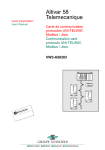
Physical presentation
Description
The TSX ESY 007 Module presents a double slot format.
Illustration:
1
3
2
4
The following table describes the diagrams according to address:
35010594 02 October 2005
Number
Description
1
Status indicator panel with 4 indicator lights for display of module operation
modes:
z RUN indicator (green): on, signals normal operation of module,
z BAT indicator (red): on, signals module fault,
z I/O indicator (red): on, signals input/output fault on I/O extension bus.
2
Status indicator panel with 16 indicator lights (0 to F) for diagnostics of racks on
the I/O extension bus.
3
Pencil point button for module reset.
4
SUB D 26-pin high-density connector for connection to the I/O extension bus.
Receives the TSX LES 64/65/74/75 terminal block connectors.
27
Module Input/Output Extension Bus Coupler Interface: TSX ESY 007
Mounting/Installation
Overview
The TSX ESY 007 Module mounts in any position on a Premium TSX RKY rack on
the main segment of bus X, except for positions dedicated for processor and power
supply. The processor is a Premium UNITY processor version V2.00 minimum.
WARNING
Not allowed in an extension rack
This module cannot operate in an extension rack (distance > 100m),
and absolutely must be assembled in a main segment rack of the X bus.
Failure to follow this instruction can result in death, serious injury,
or equipment damage.
The mounting and dismounting procedure (See Premium and Atrium UNITY Pro
Manual, Discrete input/output modules, Installation of input/output modules) is
identical to the mounting and dismounting procedure of other modules.
Installation and removal of this module is performed using a flat or cross-slot
screwdriver.
These operations can be performed whether the power is on or off, with no adverse
effect on the module or the rack holding it.
Note: Mounting and dismounting of the module may be performed with PLC power
on and I/O extension bus connected.
28
35010594 02 October 2005
Module Input/Output Extension Bus Coupler Interface: TSX ESY 007
Number of
modules per
station
The maximum number of TSX ESY 007 modules that may be installed in a
Premium/Atrium station depends on the features of the processor used. The coupler
is installed as a field bus and not as an application track.
Processor reference
Authorized TSX ESY CM 007 Module
number
TSX P57 0244
1
TSX P57 104
2
TSX P57 154
2
TSX P57 1634
2
TSX P57 204
4
TSX P57 254
4
TSX P57 2634
4
TSX P57 304
8
TSX P57 354
8
TSX P57 3634
8
TSX P57 454
8
TSX P57 4634
8
TSX P57 554
8
TSX P57 5634
8
TSX PCI57 204
4
TSX PCI57 354
7
It is recommended to choose at least a TSX P57 3xxx/4xxx/5xxx processor to
ensure proper functioning of the TSX ESY 007 Module.
For further information, refer to the following documents:
Number of field
bus connections
managed
Maximum
number of input/
outputs
managed by the
TSX ESY 007
Module
35010594 02 October 2005
z
z
Premium (See UNITY Pro Premium and Atrium User Manual, Processors, racks
and power supply, TSX 57 Processor Catalogue)
Atrium (See UNITY Pro Premium and Atrium Manual, Processors, racks and
power supply, Atrium Catalog)
The TSX ESY 007 Module may control a maximum of 16 8-slot racks.
The maximum number of I/O that it can manage is 2048 E Discrete, 2048 S Discrete,
256 E ANA and 256 S ANA.
The Series 7 Discrete, analog and working tracks controlled by the TSX ESY 007
Module are not included in the calculation of the maximum number of Discrete,
analog or application tracks of a Premium/Atrium processor.
29
Module Input/Output Extension Bus Coupler Interface: TSX ESY 007
Connections
Connecting to
the X bus
The module is automatically connected to the X bus when it is inserted into the
receiving rack. If the module is placed in the base rack, its connection with the CPU
and the power supply module is assumed. When this is not the case, the module is
powered by the power supply of the rack on which is positioned and the connection
with the processor is assured by connection of X bus to all racks.
Connecting to
the LES20 bus
The I/O extension bus connection procedure is not chronological between
equipment (Bus Master or TSX 7 Rack), but the overall operation cannot be
guaranteed during this phase of installation.
The I/O extension bus does not require a specific ground connection, on the other
hand Power Supply and PLC equipment must follow standard installation
requirements. It is recommended not to place the I/O extension bus next to highenergy cables.
The medium connection system is designed to connect by means of the
TSX CBC xxx cable. Whatever the layout, the sum of cable lengths of the same I/O
extension bus should not exceed 30 meters. Moreover, an electrical or optical
entrance link should be used.
I/O Extension
Bus Cables
The I/O extension bus cables carry signals to TSX 7 racks and modules. The
features of this cable are available in the documentation for I/O configuration
installation on TSX Series 7 modules.
Recommended Cable: TSX CBC xxx.
Cable Routing
The I/O extension bus cables and high-energy power cables must be in separate
channels, protected by a metallic divider.
When routed together with control cables, it is imperative to make control link
connections according to generally accepted practices.
30
35010594 02 October 2005
Module Input/Output Extension Bus Coupler Interface: TSX ESY 007
Connector plug
The TSX LES 64/65/74/75 terminal blocks allow connection of the module to the
I/O extension bus. These terminal blocks are connected to the I/O extension bus
cable and assembled by the user according to steps described later.
In most cases, you can use the existing TSX LES 64/65/74/75 connector from the
existing installation that was used to connect the TSX 7 processor to the I/O
extension bus.
In all cases, a TSX LES 64 or 65 terminal block will be used when the TSX ESY 007
module drives Series 7 racks as local entrance link and a TSX LES 74 or 75 terminal
block is used when it drives electrical or optical entrance link racks.
Illustration:
Connecting the
module to the
bus.
To connect the module to the bus, follow the procedure below (if no existing terminal
block is available):
Step
Action
1
Preparing the TSX LES 64/65/74/75 connection box:
z open the cover,
z connect one end of the TSX CBC chaining cable to the connecting
connector (Cf. TSX Series 7 documentation),
z close the cover.
35010594 02 October 2005
2
Position the box on the 26-pin connector of the TSX ESY 007 Module.
3
Connect the ground wire of the box to the ground lug of the case. If the ground
wire is too short to be connected to the case, replace it with a longer wire while
respecting the length/width in order to avoid "Pigtail" phenomena.
31
Module Input/Output Extension Bus Coupler Interface: TSX ESY 007
LED module status indicators
General Points
4 LED indicators located on the module, RUN, ERR, TER, I/O provide information
on module operation (LED off, blinking or on).
LED
indicators
On
Flashing
Off
RUN (green)
Module operating normally
Module self-tests (1) or in standby
for configuration
Module failure, or module
power off
ERR (red)
Serious internal fault, module
failure
Module self-tests (1) or fault:
system OK however:
z application fault or,
z I/O extension bus cables fault
No internal fault
COM (yellow)
-
Module self-tests (1)
I/O (red)
Default inputs/outputs
Module self-tests (1)
Module operating normally
(1) simultaneous flashing of all 4 LED indicators during self-tests on module powerup.
32
35010594 02 October 2005
Module Input/Output Extension Bus Coupler Interface: TSX ESY 007
Special LED indicators of the TSX ESY 007 Module
Overview
16 LED indicators allow visual inspection of operation status of TSX 7 extension
racks controlled by the TSX ESY 007 Module.
LED appearance:
Rack
0
2
4
6
8
A
C
Of
1
3
5
7
9
B
D
F
LED status:
35010594 02 October 2005
LED status:
Meaning
LED green
Corresponding rack configured in the UNITY Pro Premium
application and operating normally
LED flashing green
Corresponding rack configured in the UNITY Pro Premium
application and by default
LED off
Corresponding rack not configured in the UNITY Pro Premium
application
33
Module Input/Output Extension Bus Coupler Interface: TSX ESY 007
Technical Features
LES20 bus
34
Feature
Value
Maximum I/O extension bus scan time
50 ms
Rack number on I/O extension bus
16
Maximum length of I/O extension bus (without optical or
electrical link)
30 meters
Maximum number of inputs/outputs
2048 I/O Discrete + 256 I/O ANA
35010594 02 October 2005
Module Input/Output Extension Bus Coupler Interface: TSX ESY 007
TSX ESY 007
Module
Feature
Value
Programming the TSX ESY 007 Module
Unity Pro
Response time for 128 16-channel discrete modules in the 75 ms typical 85 ms maximum
MAST task (1)
Calculation of I/O extension bus polling time for n modules 0.192 ms x Number of 4-channel
(normal operation)
discrete modules + 0.228 ms x
Number of 8-channel discrete
modules + 0.300 ms x Number
of 16-channel discrete modules
+ 1.900 ms x Number of ANA/
Analog modules + 7.3 ms
Current consumed by 5 V PLC
75 mA typical/100 mA maximum
Power dissipation
0.5 W maximum
Level of protection
IP20
Operating temperature
0 to 60 degrees Celsius
Standards and conditions of service
In conformity with those of
Premium PLCs
(1) Logical response time = time between one I/O extension bus input activated on
the bus, processed in the PLC application and applied on an I/O extension bus
output.
Note:
The PLC scan time must be adjusted on the periodic mode and not on the scan
mode and a task period calculated according to the following formula:
"Scan time task X >= Estimated scan time of theoretical LES20 X bus task +
Execution time of programmed task X".
Program execution time for a given task may be calculated from %SW30 to 35. For
details on I/O extension bus scan time, see in Chapter 6. In debug phase,
information on the real scan time of the I/O extension bus (current and maximum)
is provided to allow more exact adjustment of the PLC scan time.
If the PLC scan time is less than the LES20 bus scan time or if the task is in scan
mode, synchronization of cycles is not guaranteed. In cases such as this, the
operation mode will be asynchronous between the PLC scan and the LES20 bus
scan.
If the PLC program uses messaging features for the TSX Series 7 modules, you
must increase the configured cycle type to enable the TSX ESY 007 module to
manage the messaging requests.
35010594 02 October 2005
35
Module Input/Output Extension Bus Coupler Interface: TSX ESY 007
User safety
Overview
To ensure user safety, you must:
z
z
z
z
Connect the PLC ground wire to the ground.
For a PLC connected to an AC networks, place a differential circuit breaker
upstream in the network to interrupt the PLC power supply in the event that a leak
with the ground is detected.
For a PLC connected to a DC power supply, to ensure that the power supply
placed upstream of the PLC is TBTS.
To use certified Schneider Electric products on the bus.
On account of its technology and connection, the TSX ESY 007 Module only
receives 5 VDC and its zero electrical volt is connected to the ground of the PLC.
36
35010594 02 October 2005
Module Input/Output Extension Bus Coupler Interface: TSX ESY 007
2.2
Use of the TSX ESY 007 Module for System
Upgrade
At a Glance
Subject of this
Section
This section covers installation of the TSX ESY 007 Module for a system upgrade.
What's in this
Section?
This section contains the following topics:
35010594 02 October 2005
Topic
Page
At a Glance
38
Installation
39
Recovering racks 0 to 3
42
For double format racks
44
LES120/LFS120 Remote Entrance Links
45
Methodology for Upgrading the PL7-3 PLC Program
47
37
Module Input/Output Extension Bus Coupler Interface: TSX ESY 007
At a Glance
Overview
The TSX ESY 007 Module is a Premium X bus module for revamping automated
systems equipped with TSX Series 7 programmable PLCs. It allows creation of a
gateway between a Premium PLC and the I/O serial extension bus of TSX Series 7
PLCs. It offers the possibility of replacing the processor of a TSX Series 7 system
by a TSX Premium processor and keeping the base racks and extension racks of
the TSC Series 7. It thus allows recovery of all in a TSX Series 7 by connecting and
controlling the LES20 series bus.
It thus offers a solution to modernize TSX Series 7 systems and benefit from
Premium / UNITY technology without having to redo all the cabling of the I/O
modules.
38
35010594 02 October 2005
Module Input/Output Extension Bus Coupler Interface: TSX ESY 007
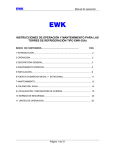
Installation
A TSX Series 7 PLC, versions V3, V4 and V5, is composed of 2 main racks
numbered 0/1 and 2/3 and 12 extension racks numbered from 4 to 15.
The two main racks are linked by a parallel bus when the extension racks are linked
to the CPU by a serial bus. Each direct extension is linked to its main extension rack
by a parallel bus.
The diagram is the following:
0/1 Rack
2/3 Rack
Parallel
bus
Serial bus
LES 64/65/74/75
5 Rack
4 Rack
Parallel
bus
LES20 Coupler + LES62
6 Rack
7 Rack
Parallel
bus
LES20 Coupler +
LES62 or 61 module
The LES20 Series 7 module manages data exchange with the TSX7 CPU. It
transforms the I/O data that it receives via serial bus into data on the parallel bus of
the extension racks. Through a TSX LES 61/62 connection box, the LES20 Series 7
module has an extension rack address representing the address of the extension
rack it manages.
35010594 02 October 2005
39
Module Input/Output Extension Bus Coupler Interface: TSX ESY 007
Special architecture
z
z
z
2/3 rack managed by a LES20 coupler.
In certain configurations, the 2/3 rack is not managed as a direct extension of the
base rack by a parallel bus, but is managed as a serial bus by a LES20 coupler.
When this is the case, the 2/3 rack may also be kept without any problem during
upgrade.
Double format rack
In version V2, 67/30, 87/10 and 87/20 processors and in version V3, 87/30
processors are positioned in the double format racks. The lower part has a
complete bus, and the upper part has a simplified bus. For 87/10 and 87/20
processors, positions 00 and 10 may be occupied by a memory extension card
(TSXMEM4x). To upgrade these configurations, a LES20 coupler should be
installed in place of the processor in the lower part of the rack.
Electrical (LES120) and optical (LFS120) remote extension
Remote input/output extensions allow entrance linkage at great distances from
base controller cases capable of supporting modules of any kind. Two
technologies may be used: entrance linkage by fiber optical bus (maximum
distance of link 2000 meters) or entrance linkage by electrical bus (maximum
distance 500 meters). Remote I/O extensions are composed of cases that have
integrated either a TSX LFS 200 optical chaining module for entrance linkage via
fiber optical bus or a TSX LES 200 electrical chaining module for entrance
linkage via electric bus. In both cases, upgrade by use of a TSX ESY 007 module
will be possible.
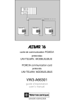
The upgrade solution offered by the TSX ESY 007 Module can substitute racks 0/1
and 2/3 with a Premium rack and keep Series 7 extension racks. Recovery of racks
0/1 and 2/3 is also possible. When this is the case, the Premium rack is added to the
top of the I/O configuration.
40
35010594 02 October 2005
Module Input/Output Extension Bus Coupler Interface: TSX ESY 007
Illustration:
0/1 Rack
LES20 Coupler
2/3 Rack
LES20 Coupler
4 Rack
5 Rack
LES20 Coupler
In the illustration below, the TSX Series 7 processor for the 0/1 rack was replaced
by a TSX LES 20 coupler. A TSX LES 20 coupler was installed in position M of the
2/3 rack. The 2/3 rack is fitted with a power supply. These two couplers were
connected to the I/O extension bus by two TSX LES 62 connector terminal blocks.
The existing TSX LES 65 terminal block that was previously plugged into the
TSX Series 7 processor is now plugged into the front panel connector of the
TSX ESY 007 coupler.
The TSX Series 7 PL7-3 processor application program was migrated to UNITY Pro
software using PL7-3/PL7 Pro and PL7 Pro/UNITY Pro converters.
35010594 02 October 2005
41
Module Input/Output Extension Bus Coupler Interface: TSX ESY 007
Recovering racks 0 to 3
At a Glance
Recovery of the 0/1 rack and the 2/3 rack managed as a direct extension is possible
when the following conditions are met:
z
z
z
Move the 2/3 rack from direct extension to local extension and install a
TSX LES 20 Coupler in slot M with a power supply. On type RKE 8 racks, there
are slots for installing a power supply and the TSX LES 20 Coupler. On the other
hand, on type RKE 7 racks these slots do not exist and the cards in the first two
slots must be removed in order to mount a power supply and the LES20 Coupler.
Install a TSX LES 20 Coupler in the place of the Series 7 CPU in the 0/1 rack.
In the LES62 terminal block of the LES20 module of the 0/1 rack, encode address
0 and in the LES62 terminal block of the LES20 module of the 2/3 rack, encode
address 2.
Encoding addresses:
D
C
B
A
Address 0
42
D
C
B
A
Address 2
35010594 02 October 2005
Module Input/Output Extension Bus Coupler Interface: TSX ESY 007
Illustration
Forward:
0/1 Rack
LES20 bus
2/3 Rack
LES 65/75
After:
0/1 Rack
LES20 Coupler
2/3 Rack
LES20 Coupler
35010594 02 October 2005
43
Module Input/Output Extension Bus Coupler Interface: TSX ESY 007
For double format racks
Recovering a double-format rack involves installing a LES20 Coupler in place of the
processor in the lower part of the rack.
Recovering I/O modules on the upper side follows the same principle as for a double
address rack. In the case of a double format direct extension I/O rack, a LES20
Coupler should be placed in slot M.
Illustration
Forward
TSX Series 7 processor
After
LES20 Coupler
to TSX ESY 007
44
35010594 02 October 2005
Module Input/Output Extension Bus Coupler Interface: TSX ESY 007
LES120/LFS120 Remote Entrance Links
At a Glance
There are two types of links in configurations with I/O remote entrance linkage:
z
z
Fiber optical remote I/O link: LFS-120,
Electric remote I/O link: LES-120.
Recuperation of this type of remote link by the TSX ESY 007 coupler is possible if
the base configuration is modified as indicated hereafter.
Optical
configuration
before
configuration:
Illustration:
A
4
3
2
C
1
1
B
C
B
B
Definitions:
Code
35010594 02 October 2005
Definition
A
PLC base tray
B
Direct extension input/output tray:
C
Remote optical direct extension input/output tray
1
TSX LFS 200 optical chaining module
2
TSX LFS 120 optical entrance link module
3
TSX LES 70 Module
4
TSX LES 74/75 Module
45
Module Input/Output Extension Bus Coupler Interface: TSX ESY 007
Optical
configuration
after upgrade:
Illustration:
3
2
5
A
To TSX ESY 007
(TSX LES 74 or 75 terminal
block)
3
4
C
1
6
B
B
Definitions:
Code
Definition
A
PLC base tray
B
Direct extension input/output tray:
C
Remote optical direct extension input/output tray
1
TSX LFS 200 optical chaining module
2
TSX LFS 120 optical entrance link module
3
TSX LES 20 Module
4
TSX LES 70 Module
5
TSX LES 62 Module
6
TSX LES 61 Module
The above principle is the same in the case of electrical entrance link architecture.
46
35010594 02 October 2005
Module Input/Output Extension Bus Coupler Interface: TSX ESY 007
Methodology for Upgrading the PL7-3 PLC Program
At a Glance
The different steps for migrating a PL7-3 program of a TSX Series 7 PLC for
updating to a UNITY Pro program are presented below. Porting a PL7-3 program to
UNITY Pro requires the successive use of PL7-3/PL7 Pro and PL7 Pro/UNITY Pro
converters. It also requires XTEL (V5 minimum), PL7-3 (V5 minimum), PL7 Pro
(V4.3 minimum) and UNITY Pro (V2.1 minimum) software.
z
z
z
z
z
z
z
z
z
Analysis of the I/O configuration of the PL7-3 program (under XTEL-CONF):
establish the list of I/O modules supported by the TSX ESY 007 Module and those
that are not supported.
Modular backup under XTEL-PL7-3 of each part of the PL7-3 (PRL, G7, POST,
Sri) program: obtain the text file (.LAD, .LIT, .GR7).
Backup the symbols file (.SCY) and the constants file (.CST)
Conversion of the exported files (.LAD, .LIT, .GR7, .SCY, .CST) to a PL7 Pro
compatible file format (.LD, .ST, .GR7, .SCY) using the PL7-3/PL7 Pro converter
associating PL7-3 and PL7 Pro objects.
Creating a PL7 Pro receiving program and successive importing of compatible
exported PL7-3 files. Be sure to respect the order in which you import the sections
to preserve the structure of the source program.
Exporting the PL7 Pro application to .FEF file.
Creating the receiving station in UNITY Pro by adding the TSX ESY 007 Module
and creating the I/O extension bus configuration.
Importing the FEF application in UNITY Pro using the PL7 Pro/UNITY Pro
converter associating PL7 Pro objects with UNITY Pro objects. The
correspondence of the Series 7 I/Os with the UNITY Pro I/Os is described in detail
in chapter 3.
Adaptation of the program to the upgrade through the use of the TSX ESY 007
Module (Porting PL7-3 instructions for explicit read/write and text block send
through the use of EF SEND_REQ in UNITY Pro).
For steps 1 to 5, see the documentation for the PL7-3/PL7 Pro converter (on-line
converter help: convpl73.hlp)
For step 8, see the documentation for the PL7 Pro/UNITY Pro converter (on-line
UNITY help).
35010594 02 October 2005
47
Module Input/Output Extension Bus Coupler Interface: TSX ESY 007
Key points for
migrating a
PL7-3 program to
UNITY Pro
Application structure:
z
z
A PL7-3 application may include up to seven tasks (six FAST/MAST/AUX0/
AUX1/AUX2/AUX3 periodic tasks and one interruption task. A UNITY Pro
application using the TSX ESY 007 Module can only include the MAST and FAST
tasks for the I/O configured on the LES20 Bus.
Modular backup and import of each part of the program involves a loss of
program structure. Successful recovery of this structure is the responsibility of the
user when importing into PL7 Pro. Because the PL7-3 task number is greater
than the PL7 Pro task number, there may be collision problems that must be
resolved by the user.
Objects:
z
z
Objects handled by a PL7-3, PL7 Pro or UNITY Pro application are predefined.
Some PL7-3 objects still exist in PL7 Pro and UNITY Pro, others not. A key point
in conversion is to associate each PL7-3 object used with its equivalent in
PL7 Pro then UNITY Pro.
Converter documentation contains correspondence tables for PL7-3/PL7 Pro and
PL7 Pro/UNITY Pro objects.
Languages syntax:
z
z
z
48
The PL7-3 (LIT) literal language is transformed into structured language in
PL7 Pro and UNITY Pro (ST). Syntactical differences exist between the two
languages. A table of equivalencies is available in the documentation of the
converters.
The Ladder PL7-3 language is not processed in the same manner as the Ladder
PL7 Pro and UNITY Pro language. In PL7-3, the Ladder is processed, for each
rung, from left to right, column by column, and in each column from top to bottom.
In PL7 Pro and UNITY Pro, the Ladder is processed connected network by
connected network, and within a connected network, in the direction of the
equation. Even though they are converted in identical graphical form, some
networks of contacts may thus be processed differently (producing a different
result on execution).
The Grafcet language is transformed in UNITY Pro into SFC language. Because
of this, some functions no longer exist and their migration is the responsibility of
the user (Section PRL/POST, Jump,). Moreover, some execution rules are
different (empty receptivity, macro steps). See the converter documentation for
more information on the differences between Grafcet and the SFC language.
35010594 02 October 2005
Module Input/Output Extension Bus Coupler Interface: TSX ESY 007
Hardware and software configuration:
z
Software configuration is partially recovered. Configuring task parameters,
memory (number of internal bits/words), management of common words and
OFBs, information relating to Grafcet are not recovered and are the responsibility
of the user.
Explicit exchange instructions:
z
z
35010594 02 October 2005
Because the converters are not able to preserve the explicit exchange
instructions with Series 7 modules, porting instructions is the user's responsibility.
The READEXT and WRITEEXT instructions, as well as the exchanges by text
block send may be reproduced by using EF SEND_REQ and request send to the
TSX ESY 007 Module.
49
Module Input/Output Extension Bus Coupler Interface: TSX ESY 007
2.3
Input/Output Extension Bus Diagnostics
I/O extension bus diagnostics - Presentation
Overview
LED indicators block for the modules allows:
z
z
Indicator lights for the presence of each TSX7 rack configured in the UNITY Pro
application.
Indicator lights for the status of these TSX7 racks configured in the UNITY Pro
application.
Illustration:
A green LED on indicates whether the corresponding TSX7 rack or one of its
modules has a communication fault.
A flashing green LED indicates that the corresponding TSX7 rack or one of its
modules has a communication fault.
50
35010594 02 October 2005
Module Input/Output Extension Bus Coupler Interface: TSX ESY 007
2.4
Operating Modes of the TSX ESY CM 007 Module
TSX ESY 007 Module Operating Modes
Output fallback
strategy
The fallback mode is defined for each TSX 7 rack in the configuration screen and
may be read in the word %KWr.m.0:
z
z
%KWr.m.0.i = 0: I/O fallback to 0 of the Series 7 rack number i on the I/O
extension bus
%KWr.m.0.i = 1: maintain I/O status of the Series 7 rack number i on the I/O
extension bus
(r = address rack TSX ESY 007, m = TSX ESY 007 address module)
Operation:
On communication fault of TSX ESY 007 Module with TSX LES20 coupler:
z
z
With fallback option to 0: outputs of this rack are forced to 0 until communication
resumes.
With Maintain status option: outputs of this rack are maintained in status until
communication resumes.
Communication
fault
In case of communication break with the CPU, following a CPU watchdog (in case
of placement of TSX ESY 007 Module in the main rack), or removal of the X Bus
cable (in the case of a placement of TSX ESY 007 Module in an extension rack), the
module sends outputs in fallback to 0 or to maintain according to the chosen
configuration.
Extracting a
module with
power on
When extracting a module with power on, communication with the X bus stops, the
processor signals a module fault.
Module Fault
In the event of a serious TSX ESY 007 Module fault (defective component, etc.), the
module stops communicating with the X Bus and with the I/O extension bus. The
same behavior also occurs when extracting a module with power on.
Inserting a
module with
power on
After power-up, the TSX ESY 007 Module waits to receive the configuration from the
processor, until which it remains stopped.
35010594 02 October 2005
Communication on the I/O extension bus is also interrupted with warning. In this
case, the Series 7 racks put their outputs in the desired status (maintain or fallback).
51
Module Input/Output Extension Bus Coupler Interface: TSX ESY 007
Outage of I/O
extension
medium
In the event of medium outage, several situations are possible:
z
z
z
52
The medium is cut off or disconnected from the module output: Disappearance of
all Series 7 modules and activation of corresponding channel fault bits and the
module fault bit.
The medium is disconnected from some Series 7 racks (the TSX LES 61/62
terminal blocks are present but disconnected from the TSX LES 20 modules):
Disappearance of disconnected Series 7 modules and activation of
corresponding channel fault bits and the module fault bit. Communication with the
remaining Series 7 Modules is maintained. The disconnected Series 7 racks
enter fallback or maintain mode according to their configurations.
The medium is cut off after the TSX ESY 007 Module and several Series 7 racks
(complete cut off of the medium): Disappearance of disconnected Series 7
modules and activation of corresponding channel fault bits and the module fault
bit. Communication with the remaining modules is possible but possibly affected
by communication error. The disconnected Series7 racks enter fallback or
maintain mode according to their configurations.
35010594 02 October 2005
Module Input/Output Extension Bus Coupler Interface: TSX ESY 007
2.5
Precautions for Use
Double rack addressing
Recommendations
When connecting the I/O extension bus to the TSX ESY 007 Module, do not assign
the same address to two Series 7 racks by encoding TSX LES 61/62 module
terminal blocks or encoding LES200 and LFS200.
Illustration
A single combination of the connectors below by terminal block LES61/62.
RACKS
0/1
2/3
4/5
6/7
OUT
EXAMPLE
6 7 RACKS
Strap position:
RACKS
8/9
A/B
D
C
B
A
IN
D
C
B
A
C/D
35010594 02 October 2005
E/F
D
C
B
A
53
Module Input/Output Extension Bus Coupler Interface: TSX ESY 007
54
35010594 02 October 2005
Software Installation for the
TSX ESY 007 Module
III
At a Glance
Subject of this
Section
This section covers software installation for the TSX ESY 007 Module with
UNITY Pro software.
What's in this
Part?
This part contains the following chapters:
35010594 02 October 2005
Chapter
Chapter Name
Page
3
TSX ESY 007 Module Software Installation - Principles
57
4
Configuring the TSX ESY 007 Module
75
5
Debugging the TSX ESY 007 Module
89
6
Performance of the TSX ESY 007 Module
99
7
Language Objects of the TSX ESY 007 Module
101
55
Software Installation for the TSX ESY 007 Module
56
35010594 02 October 2005
TSX ESY 007 Module Software
Installation - Principles
3
At a Glance
Subject of this
Chapter
This chapter presents the software installation principles for the TSX ESY 007
Module.
What's in this
Chapter?
This chapter contains the following topics:
35010594 02 October 2005
Topic
Page
Installation of the I/O extension bus - Presentation
58
TSX ESY 007 Module Architecture
60
Structure of a Series 7 module
61
Addressing Language Objects Associated with Series 7 Devices On the I/O
Extension Bus
63
Use of EF SEND_REQ for Handling Series 7 Modules with Extended and
Message Registers
65
57
Principles TSX ESY 007 Module Software Installation
Installation of the I/O extension bus - Presentation
Introduction
The TSX ESY 007 Module allows Series 7 rack control via a Premium PLC
programmed with Unity Pro software. The TSX ESY 007 Module is used for
revamping automated systems equipped with TSX Series 7 programmable PLCs. It
allows creation of a gateway between a Premium PLC and the I/O serial extension
bus of TSX Series 7 PLCs. It offers the possibility of replacing the main rack of a
TSX Series 7 system by a TSX Premium rack and keeping the TSX Series 7
extension racks. It thus allows recuperation of all extension racks in a TSX Series 7
by connecting and controlling the input/output serial extension bus.
It thus offers a solution to modernize TSX Series 7 systems and benefit from
Premium / UNITY technology without having to redo all the cabling of the I/O
modules.
Installation of the TSX ESY 007 Module frame requires definition of the physical
context of the project in which it will be used (rack, power supply, processor,
modules, Series 7 devices connected by the bus), followed by installation of the
software. The software installation of the application-specific modules is carried out
from the various Unity Pro editors:
z
z
in offline mode,
and in online mode.
The following order of installation phases is recommended but it is possible to
change the order of certain phases (for example, starting with the configuration
phase).
58
35010594 02 October 2005
Principles TSX ESY 007 Module Software Installation
Installation of the
TSX ESY 007
Module
The table below shows the various phases of installation of the TSX ESY 007
Module:
Phase
Description
Mode
Declaration of variables
Declaration of IODDT-type variables for the applicationspecific modules and project variables.
Offline (1)
Programming
Programming of the project and functions of the TSX ESY 007 Offline (1)
Module.
Configuration
Declaration of Series 7 modules and devices.
Module channel configuration.
Entry of configuration parameters.
Offline
Association
Association of IODDTs with the modules configured (variable
editor).
Offline (1)
Build
Project generation (analysis and editing of links).
Offline
Transfer
Transfer project to PLC.
Online
Adjustment / Debugging
Debug project from debug screens, animation tables.
Modifying the program and adjustment parameters.
Online
Documentation
Building documentation file and printing miscellaneous
information relating to the project.
Online (1)
Operation / Diagnostic
Displaying miscellaneous information necessary for
supervisory control of the project.
Diagnostic of project and modules.
Online
(1): These various phases can also be performed in the other mode.
*: Predefined structure containing standard language objects of the module.
35010594 02 October 2005
59
Principles TSX ESY 007 Module Software Installation
TSX ESY 007 Module Architecture
At a Glance
The TSX ESY 007 Module operates according to master/slave modes. The master
alone commands exchanges on the bus.
The module integrates data fields that allow to manage Series 7 module lists and the
images of input/output data.
Illustration of the
architecture
The figure below shows the architecture of the TSX ESY 007 Module.
TSX ESY 007
Description of
components
60
1
I/O data
2
Messaging
data
3
Configuration
4
Current
parameters
I/O extension bus
The table below shows the different elements that make up the architecture of the
TSX ESY 007 Module.
Address Element
Description
1
I/O data
Images of the I/O of the 16 8-slot racks.
2
Messaging data
Image of the messages sent to Series 7 modules.
3
Configuration
This field contains all the codes of the Series 7 I/O
modules configured on the I/O extension bus.
4
Current parameters
Image of the parameters of all Series 7 modules and
racks.
35010594 02 October 2005
Principles TSX ESY 007 Module Software Installation
Structure of a Series 7 module
At a Glance
The TSX ESY 007 Module allows to control the 128 Series 7 devices in the following
list:
Discrete I
Discrete O
I ANA
O ANA
Other
TSX DET 4 66
TSX DST 4 17
TSX AEM 4 11
TSX ADT 2 01
TSX AXT 2 00
TSX DET 8 02
TSX DST 8 04
TSX AEM 4 12
TSX ADT 2 02
TSX CCM 1 00
TSX DET 8 03
TSX DST 8 05
TSX AEM 4 13
TSX ADT 2 03
TSX CTM 1 00
TSX DET 8 05
TSX DST 8 17
TSX AEM 8 11
TSX AST 2 00
TSX DTM 1 00
TSX DET 8 12
TSX DST 8 35
TSX AEM 8 21
TSX ASR 2 00
TSX DMR 16 52
TSX DEM 24xx
TSX DET 8 13
TSX DST 8 82
TSX AEM 12 12
TSX ASR 4 01
TSX DET 8 14
TSX DST 16 04
TSX AEM 16 01
TSX ASR 4 02
TSX DET 8 24
TSX DST 16 12
TSX AEM 16 02
TSX ASR 4 03
TSX DET 16 03
TSX DST 16 32
TSX AEM 16 13
TSX ASR 8 00
TSX DET 16 04
TSX DST 16 33
TSX DET 16 12
TSX DST 16 34
TSX DET 16 13
TSX DST 16 35
TSX DET 16 33
TSX DST 16 82
TSX DET 32 12
TSX DST 24 72
TSX DET 32 32
TSX DST 24 82
TSX DET 32 42
TSX DST 32 92
TSX DET 32 52
The Discrete input modules have 4, 8 or 16 input channels. The-32 channel modules
are represented as two 16-channel modules in the same slot of the even-numbered
rack and the next odd-numbered rack.
Discrete output modules have 4, 8 or 16 output channels. The 32-channel modules
are represented as two 16-channel modules in the same slot of the even-numbered
rack and the next odd-numbered rack.
The ANA input modules have 16 Discrete channels, 8 analog input channels and
8 analog output channels. Some even have an internal memory area called
"extended registers" that allow management of more than 8 analog channels.
The ANA output modules have 16 Discrete output channels, 8 analog input channels
and 8 analog channels for output.
35010594 02 October 2005
61
Principles TSX ESY 007 Module Software Installation
The other ANA modules have either:
z
z
z
16 Discrete input channels, 8 analog input channels and 8 analog output
channels.
16 Discrete output channels, 8 analog input channels and 8 analog output
channels.
8 Discrete input channels, 8 Discrete output channels, 8 analog input channels
and 8 analog output channels.
Some also have an internal memory area called "extended registers" that allow
management of more than 8 analog channels and a second internal memory area
called "message registers" that allows management of messages.
62
35010594 02 October 2005
Principles TSX ESY 007 Module Software Installation
Addressing Language Objects Associated with Series 7 Devices On the I/O
Extension Bus
At a Glance
Acquisition of inputs and updating of outputs from Series 7 devices connected to the
I/O extension bus are performed in two different ways based on the channel type at
the start and the end of each device type:
z
z
automatically, respectively at the beginning and at the end of each scan of the
task for which they are configured for the Discrete and ANA implicit I/O objects,
by messaging with the use of EF SEND_REQ for objects based on extended
registers and message registers.
The program user has access to these inputs and these outputs by language
objects.
Addressing is defined as follows:
Syntax
35010594 02 October 2005
%
I,Q,IW,QW \
b.1
Symbol
Object type
Bus number
followed by .1
\
r
.
Rack No.
m
Module
position
.
c
channel
The table below describes the different elements included in addressing:
Family
Element
Values
Meaning
Symbol
%
-
-
Object type
I
Q
IW
QW
-
Image of the All or None module input,
Image of the All or None module output,
Image of the analog input of the module,
Image of the analog output of the module,
This information is exchanged automatically for
each cycle of the task to which they are
attached.
Bus no.
b
2 to 999
Bus number (assigned by UNITY Pro)
Rack No.
r
0 to 15
Series 7 rack number
Module position
m
0 to 7
Series7 module number
Channel
c
0 to 15
Channel number
63
Principles TSX ESY 007 Module Software Installation
Example
%I\3.1\0.2.6 indicates: input 6 of Series 7 module in slot 2 of 0 rack (formerly I2,6 in
PL7-3).
Illustration:
I/O extension bus
Rack address
4
6
0 1 2 3 4 5 6 7
0 1 2 3 4 5 6 7
Module
I/O address
%I\3.1\4.4.0 to 15
%IW\3.1\6.1.0 to 7
%Q\3.1\4.6.0 to 7
Word bit
addressing for
an analog
variable
%QW\3.1\6.3.0 to 7
To address a word bit, comply with the following syntax:
%
IW/QW
\b.1\
r
Symbol
Object type
Bus number
followed by .1
Rack No.
.
m
Module
position
.
c
Channel
.0.
i
Bit position
Example: %IW\3.1\0.5.6.0.4 indicates: bit 4 of analog input 6 for the Series 7 module
in slot 5 of rack 0 (formerly IW5,6:X4 in PL7-3).
Multiple
addressing
When connecting one or several Series 7 racks, do not assign an address already
used by another rack on the bus.
In the event of double rack addressing, two cases can occur:
z
z
64
the two racks are composed of the same I/O modules: the TSX ESY 007 Module
does not detect any error on output modules but detects transmission errors on
the input modules,
the two racks are not composed of the same I/O modules: the TSX ESY 007
Module does not detect any error on identical modules but detects transmission
errors on the different modules.
35010594 02 October 2005
Principles TSX ESY 007 Module Software Installation
Use of EF SEND_REQ for Handling Series 7 Modules with Extended and
Message Registers
At a Glance
Some Series 7 modules have a specific operation mode for management of analog
channels and for management of their internal configuration. They have two internal
memory areas respectively called "extended register" and "message register".
The former allows management of analog channels and the latter allows
management of module configuration modes.
Management
with PL7-3
PL7-3 software allowed, thorough the use of the "send text block, explicit read/write"
functions to communicate with the extended register areas and message register
areas of the Series 7 Modules.
The table below describes the different PL7-3 functions for dialogue with the
extended and message registers:
Instruction
Meaning
READEXT
Read Series 7 module extended registers and store in a PLC internal word
area.
WRITEEXT
Write Series 7 module extended registries from a PLC internal word area.
CPL TXT
Coupler type text block for sending PLC internal words area and receiving
data for configuration, reading data and diagnostic of Series 7 module.
Note: For all additional information on the use of explicit read/write instructions and
sending text block (procedure for transfer of a configuration for example), see the
TSX Series 7 documentation.
Management
using Unity Pro
The TSX ESY 007 Module allows, with the use of EF SEND_REQ, emulation of
PL7-3 instructions for managing Series 7 modules with extended and message
registries.
With the TSX ESY 007 Module, EF SEND_REQ is used in the following manner:
SEND_REQ(ADDR('r.m.SYS'),C,%MWx:x,%MWy:4,%MWz:z); with
z
z
z
z
35010594 02 October 2005
ADDR('r.m.SYS') address encoding of the TSX ESY 007 Module,
C the request code to send to the TSX ESY 007 Module ,%MWx:x the table
containing data to send to the TSX ESY 007 Module,
%MWy:4 the exchange management table with the TSX ESY 007 Module,
%MWz:z the receive table of the TSX ESY 007 Module response.
65
Principles TSX ESY 007 Module Software Installation
Illustration
Send identification request
if RE (%M0) then
%mw13:=0;
SEND_REQ(ADDR(‘0.4.SYS’),16#0F,%MW0:1,%MW10:4,%MW100:24);
end_if;
Illustration
Send request for read object
if RE (%M0) then
%mw13:= 8;
%MW0: = 16#0696;
%MW1: = 16#0101;
%MW2: = 16#00FF;
%MW3: = 16#0001;
SEND_REQ(ADDR(‘0.4.SYS’),16#82,%MW0:4,%MW10:4,%MW100:24);
end_if;
The table containing data to send to the coupler (%MW0:4 in the illustration above)
contains a series of bytes representing the send request. The contents and length
of this table depends on the type of request to send.
The management table of the data exchange with the coupler (%MW10:4 in the
illustration above) is a 4-word table containing the following information:
System data
User data
Word number
Most significant bit of the Least significant bit of the word
word
1
Exchange number
Activity bit
2
Request response
Communication result
3
Timeout to apply to the request
4
Length of request to be broadcast, then length received in response.
The receive table (%MW100:24 in the above illustration) contains the response
request sent by the TSX ESY 007 Module. The contents and length of this table
depend on the type of send request.
66
35010594 02 October 2005
Principles TSX ESY 007 Module Software Installation
Read extended
registers
To emulate the READEXT instruction with the TSX ESY 007 Module, the EF
SEND_REQ parameters are the following:
Parameter
Meaning
Values (hexadecimal)
ADDR(‘r.m.SYS’)
address encoding of the TSX ESY 007
Module
C
request code
82
%MWx:4
table containing send data
0696,FFii,00FF,0001 with ii the address of the Series
7 recipient (rack*8 + module = 0 to 127)
%MWy:4
exchange management table
xxxx,xxxx (exchange result), 000A (exchange
timeout), 0008 (transmit time except for DEM24xx
modules with the request code 1 which requires a
length of 12)
%MWz:20
response receive table
only if response.
The management and receive tables contain the following data if the exchange was
successful:
z
z
z
z
z
z
z
35010594 02 October 2005
%MWy[1]=16#B200,
%MWy[3]=
z 16#002A if TSX AEM 1601/1602/1603 module,
z 16#0024 if TSX AEM 1212 module,
z 16#001C if TSX AEM 821 module,
%MWz[0-2] contains the request header: 16#0696, 16#FFii, 16#0100,
%MWz[3] contains the status of the exchange with the Series 7 module (16#FE
if exchange OK, 16#FD if exchange KO),
%MWz[4 to 19] contains the data for the 16 analog channels for the
Series 7 TSX AEM 16xx modules,
%MWz[4 to 16] contain the data for the 13 analog channels for the
Series 7 TSX AEM 1212 module (13th channel: Cold Junction),
%MWz[4 to 11] contain the data for the 8 analog channels for the
Series 7 TSX AEM 821 module.
67
Principles TSX ESY 007 Module Software Installation
Illustration
if RE (%M1) then
%mw13:= 8;
%MW0: = 16#0696;
%MW1: = 16#FF01;
%MW2: = 16#00FF;
%MW3: = 16#0001;
SEND_REQ(ADDR(‘0.4.SYS’),16#82,%MW0:4,%MW10:4,%MW100:20);
end_if;
Note: Use of EF SEND_REQ to reproduce a READEXT instruction is only
possible on the following module: TSX AEM 821, TSX AEM 1212, TSX AEM 1601,
TSX AEM 1602 and TSX AEM 1613.
Write extended
registers
To emulate the WRITEEXT instruction with the TSX ESY 007 Module, the EF
SEND_REQ parameters are the following:
Parameter
Meaning
Values (hexadecimal)
ADDR(‘r.m.SYS’)
address encoding of the TSX ESY 007
Module
C
request code
83
%MWx:20
table containing send data
0696,FEii,00FF,0001,jj...jj with ii the address of the
destination Series 7 module (rack*8 + module = 0 to
127) and jj..jj the data for the 8 registers for the
TSX ASR 800 module
%MWy:4
exchange management table
xxxx,xxxx (exchange result), 000A (exchange
timeout), 0018 (transmit time)
%MWz:4
response receive table
only if response.
The management and receive tables contain the following data if the exchange was
successful:
z
z
z
z
68
%MWy[1]=16#B300,
%MWy[3]=16#0008,
%MWz[0-2] contains the request header: 16#0696, 16#FEii, 16#0100,
%MWz[3] contains the status of the exchange with the Series 7 module (16#FE
if exchange OK, 16#FD if exchange KO).
35010594 02 October 2005
Principles TSX ESY 007 Module Software Installation
Illustration
if RE (%M2) then
%mw13 := 16#28;
%MW0: = 16#0696;
%MW1: = 16#FE01;
%MW2: = 16#00FF;
%MW3: = 16#0001;
%MW3: = 16#1234;
...
SEND_REQ(ADDR(‘0.4.SYS’),16#83,%MW0:20,%MW10:4,%MW100:4);
end_if;
Note: Use of EF SEND_REQ to reproduce a WRITEEXT instruction is only
possible on the TSX ASR 800 module.
35010594 02 October 2005
69
Principles TSX ESY 007 Module Software Installation
Read message
registers
To emulate the use of send text block to read data using the TSX ESY 007 Module,
the parameters of the EF SEND_REQ instruction are the following:
Parameter
Meaning
Values (hexadecimal)
ADDR(‘r.m.SYS’)
address encoding of the TSX ESY 007
Module
C
request code
82
%MWx:4
table containing send data
0696,jjii,00FF,00kk, nn..nn with ii the address of the
Series 7 destination module (rack*8 + module = 0 to
127), jj the request code (1=read data, 3= read
threshold 0 value, 5= read threshold 1 value,
41=read configuration, 47= read default chain,
4A=read application name, F=read version, F7=
read parameters) and kk the amount of data in bytes:
see table below)
%MWy:4
exchange management table
xxxx,xxxx (exchange result), 000A (exchange
timeout), 0008 (transmit time)
%MWz:zz
response receive table
only if response.
The management and receive tables contain the following data if the exchange was
successful:
z
z
z
z
z
%MWy[1]=16#B200,
%MWy[3]=16#00xx where xx is the length received according to the request
(kk+8),
%MWz[0-2] contains the request header: 16#0696, 16#jjii, 16#kk00,
%MWz[3] contains the status of the exchange with the Series 7 module (16#81 if
exchange OK for request 16#01, 16#83 if exchange OK for request 16#03, 16#85
if exchange OK for request 16#05, 16#71 if exchange OK for request 16#41,
16#77 if exchange OK for request 16#47, 16#7A if exchange OK for request
16#4A, 16#3F if exchange OK for request 16#0F, 16#FD if exchange KO),
%MWz[4 to kk+4] contains the data received.
TSX Series 7 Module Request code (Hexa)
Length (decimal)
Meaning
AEM 411/412/413
41
4 to 36 bytes
Read configuration
47
6 bytes
Character string fault
4A
1 to 20 bytes
Read application name
F
27 bytes
Read version
70
35010594 02 October 2005
Principles TSX ESY 007 Module Software Installation
TSX Series 7 Module Request code (Hexa)
Length (decimal)
Meaning
AEM 811/821
1
16 bytes
Read 8 channel ANA,
3
16 bytes
Read threshold 0
5
16 bytes
Read threshold 1
41
4 to 68 bytes
Read configuration
47
10 bytes
Character string fault
4A
1 to 20 bytes
Read application name
AEM 1212
AEM 1601/1602
AEM 1613
CCM 100
CTM 100 / DTM 100
35010594 02 October 2005
F
27 bytes
Read version
1
26 bytes
Read 12 channels ANA, + Cold Junction
41
74 bytes
Read configuration
47
10 bytes
Character string fault
4A
1 to 20 bytes
Read application name
F
27 bytes
Read version
1
32 bytes
Read 16 channel ANA,
41
34 bytes
Read configuration
47
12 bytes
Character string fault
4A
1 to 20 bytes
Read application name
F
27 bytes
Read version
1
32 bytes
Read 16 channel ANA,
3
32 bytes
Read threshold 0
5
32 bytes
Read threshold 1
41
98 bytes
Read configuration
47
12 bytes
Character string fault
4A
1 to 20 bytes
Read application name
F
27 bytes
Read version
41
16/18 or 6 to 92 bytes
Read configuration
47
4 bytes
Character string fault
4A
1 to 20 bytes
Read application name
F
27 bytes
Read version
41
16 or 6 to 108 bytes
Read configuration
47
4 bytes
Character string fault
4A
1 to 20 bytes
Read application name
F
27 bytes
Read version
F7
2 bytes
Read parameters before PWF
71
Principles TSX ESY 007 Module Software Installation
TSX Series 7 Module Request code (Hexa)
DEM 24xx
Write message
registers
Length (decimal)
Meaning
1
1 to 234 bytes
Read setpoints
41
18 bytes
Read configuration
47
12 bytes
Character string fault
4A
1 to 20 bytes
Read application name
F
27 bytes
Read version
To emulate the use of send text block to write data using the TSX ESY 007 Module,
the parameters of the EF SEND_REQ instruction are the following:
Parameter
Meaning
Values (hexadecimal)
ADDR(‘r.m.SYS’)
address encoding of the TSX ESY 007
Module
C
request code
83
%MWx:xx
table containing send data
0696,jjii,00FF,00kk, nn..nn with ii the address of the
Series 7 destination module (rack*8 + module = 0 to
127), jj the request code (2= read threshold value 0
or time, 4=write threshold value 1, 40=write
configuration, 49=write application name) and kk the
amount of data in bytes, based on the request (see
table below) and nn..nn the data to send
%MWy:4
exchange management table
xxxx,xxxx (exchange result), 000A (exchange
timeout), 00mm (transmit time with mm=kk+8)
%MWz:4
response receive table
only if response.
The management and receive tables contain the following data if the exchange was
successful:
z
z
z
z
%MWy[1]=16#B300,
%MWy[3]=16#0008,
%MWz[0-2] contains the request header: 16#0696, 16#jjii, 16#kk00,
%MWz[3] contains the status of the exchange with the Series 7 module (16#FE
if exchange OK, 16#FD if exchange KO).
TSX Series 7
Module
Request code (Hexa)
Length (Decimal)
Meaning
AEM 411/412/413
40
4 to 36 bytes
Write configuration
49
1 to 20 bytes
Write application name
72
35010594 02 October 2005
Principles TSX ESY 007 Module Software Installation
TSX Series 7
Module
Request code (Hexa)
Length (Decimal)
Meaning
AEM 811/821
2
16 bytes
Write threshold 0
4
16 bytes
Write threshold 1
40
4 to 68 bytes
Write configuration
49
1 to 20 bytes
Write application name
40
74 bytes
Write configuration
49
1 to 20 bytes
Write application name
40
34 bytes
Write configuration
49
1 to 20 bytes
Write application name
2
32 bytes
Write threshold 0
4
32 bytes
Write threshold 1
40
98 bytes
Write configuration
49
1 to 20 bytes
Write application name
40
16/18 or 6 to 92 bytes
Write configuration
49
1 to 20 bytes
Write application name
AEM 1212
AEM 1601/1602
AEM 1613
CCM 100
CTM 100 / DTM 100
DEM 24xx
Error
management
40
16 or 6 to 108 bytes
Write configuration
49
1 to 20 bytes
Write application name
2
8 bytes
Write
40
18 bytes
Write configuration
49
1 to 20 bytes
Write application name
If an exchange error occurs between the EF SEND_REQ and the TSX ESY 007
module, an error request code (16#FD) is returned in the second exchange
management table word.
16#FD returned may mean the following:
z
z
z
z
z
z
z
35010594 02 October 2005
module TSX ESY 007 absent or faulty,
maximum number of requests processed per TSX ESY 007 module (4/mast
cycle) attained,
exchange destination module TSX Series 7 absent or faulty,
exchange destination module TSX Series 7 cannot support request,
exchange destination module TSX Series 7 cannot support length to be written,
exchange destination module TSX Series 7 cannot support length to be read,
exchange destination module TSX Series 7 not ready.
73
Principles TSX ESY 007 Module Software Installation
74
35010594 02 October 2005
Configuring the TSX ESY 007
Module
4
At a Glance
Subject of this
Chapter
This chapter describes the configuration process during set-up of the I/O extension
bus.
What's in this
Chapter?
This chapter contains the following topics:
June 2005 35010594_00
Topic
Page
Declaring a TSX ESY 007 Module in the PLC rack
76
Description of the Configuration Screen of a TSX ESY 007 Module
77
Declaring a Series 7 Device to the TSX ESY 007 Module
79
Displaying the I/O Extension Bus in the Project Browser
82
Modifying the software configuration of a TSX ESY 007 Module
84
Accessing the Description of a Series 7 Module
85
Accessing the Description of a Series 7 Rack.
86
Accessing the Description of a Series 7 Module
87
Modifying General Parameters of a Series 7 Rack
88
75
Configuring the TSX ESY 007 Module
Declaring a TSX ESY 007 Module in the PLC rack
Procedure
Step
This operation allows insertion of a TSX ESY 007 Module in the PLC rack.
Action
1
Open the hardware configuration editor.
2
Select the slot in which you wish to insert the module.
3
Select the New device command in the context menu.
Result: The New device window appears.
New Device
3
Address:
Product reference
Description
Premium Local I/O Station
Analog
Remote X Bus
Communication
4
Develop the Premium local input/output station and the Communication lines by clicking on the
+ sign.
Result:
New device
3
Address:
Product reference
Description
Premium local I/O station
Analog
Remote X bus
Communication
5
76
TSX ETY 007
LES20 Module
TSX ETY 110
TCP IP ETHWAY MODULE
Select the TSX ESY 007 Module then confirm by clicking on OK.
June 2005 35010594_00
Configuring the TSX ESY 007 Module
Description of the Configuration Screen of a TSX ESY 007 Module
At a Glance
The configuration screen is a graphic tool designed for configuring a selected
module in a rack. It provides access to the module's parameters and to devices on
the I/O extension bus.
The configuration of this coupler in UNITY Pro is protected by access rights. These
rights may only be used by Schneider Services Industries entities in France, and
abroad by Schneider Services entities or otherwise by its representatives.
Illustration
The diagram below shows a configuration screen.
0.4 : TSX ESY 007
LES20 module
Description
Config
LES20 bus
I/O objects
Information
0 Rack
0
1:TSX DET 8 03
2
3
4
5
6
7
1 Rack
2 Rack
3 Rack
4 Rack
5 Rack
6 Rack
7 Rack
8 Rack
9 Rack
A Rack
B Rack
C Rack
Input/output symbols
Channel
Address
1 %I\3.1\0.1.0
2 %I\3.1\0.1.1
3 %I\3.1\0.1.2
4 %I\3.1\0.1.3
5 %I\3.1\0.1.4
6 %I\3.1\0.1.5
7 %I\3.1\0.1.6
8 %I\3.1\0.1.7
9
10
11
12
13
14
15
16
17
18
19
20
Description: 8 independ. inputs 48 VAC
Symbol
Task:
MAST
Scan duration calculated for the LES20:
Mast:
1
ms
Fast:
0
ms
The front tab indicates the currently used mode (Config in this example). Each
mode may be selected using the tab for the mode.
June 2005 35010594_00
77
Configuring the TSX ESY 007 Module
The following modes are available:
z
z
z
z
Description,
Config (configuration),
Debug (or Diagnostics), accessible only in online mode.
Diagnostics (Fault) only accessible in online mode.
The I/O objects tab (See UNITY Pro Manual, Operation modes, I/O objects tab for
a module) allows to presymbolize the I/O objects.
The configuration screen allows you to choose or view the following features:
z
z
z
z
z
The behavior of the Series 7 rack in fallback mode,
The entrance link of the Series 7 rack (local, electrical or optical),
The task controlling a Series 7 module,
The I/O objects of a Series 7 module,
The theoretical scan time of the I/O extension bus in milliseconds for MAST and
FAST tasks.
Note: The PLC scan time must be configured in periodic mode and not in scan mode
and with a task period calculated according to the following formula:
"Mast/Fast task scan time> Theoretical Mast/Fast I/O bus scan time + Execution
time of the Mast/Fast program task".
The execution time of the program for a given task may be calculated from %SW30
to 35. Please see Chapter 6 for details on I/O extension bus scan time.
In debug phase, information on the real scan time of the I/O extension bus (current
and maximum) is provided to allow more exact adjustment of the PLC scan time.
If using messaging with the TSX Series 7 modules by EF SEND_REQ, also provide
request processing time during the master task period.
78
June 2005 35010594_00
Configuring the TSX ESY 007 Module
Declaring a Series 7 Device to the TSX ESY 007 Module
At a Glance
The Unity Pro software offers a catalog including all Series 7 modules available.
This catalog is structured in families:
z
z
z
z
z
Procedure
discrete inputs,
discrete outputs,
ANA inputs,
ANA outputs,
other.
This operation is used to declare a Series 7 device on the I/O extension bus.
Step
Action
1
Access the hardware configuration screen of the TSX ESY 007 Module.
2
In the I/O extension bus field, double click in the cell corresponding to the receiving slot number of the
new device (0 rack to F, slot 0 to 7) or select that cell then execute the Edit command. Add a Series 7
module.
Results: The Add a module screen appears.
Add devices
TSX 7 families
Code
TSX family name
0
Discrete inputs
1
Discrete outputs
2
Analog inputs
3
Analog outputs
4
Other
Catalog of TSX 7 modules
Code
OK
June 2005 35010594_00
Description
Cancel
79
Configuring the TSX ESY 007 Module
Step
Action
3
In the TSX7 family name field, select the desired family.
Results: The Modules catalog linked to the selected family appears.
Adding devices
TSX 7 families
Code
TSX 7 family name
0
Discrete inputs
1
Discrete outputs
2
Analog inputs
3
Analog outputs
4
Other
TSX 7 Catalog: Discrete outputs
Code
Description
TSX DST 4 17 4 Outputs 24/48 VDC 2A/Prot.LP
TSX DST 8 04 8 Outputs 110/127 VAC 1 A
TSX DST 8 05 8 Outputs 110/240 VAC 2 A
TSX DST 8 17 8 Outputs 24/48 VDC 0.5A/Prot.LP
TSX DST 8 35 8 Outputs Rel. Ind. (1A/240VAC)
OK
Cancel
4
In the Modules catalog select the desired device.
5
Click OK to confirm your choice.
Result: The Series 7 device is defined in its slot, the device reference appears opposite the slot number.
6
To declare other Series 7 devices on the TSX ESY 007 Module, repeat the step 2 procedure.
Note: When adding the first device, the following message may appear:
TSX 7 I/O editor
Step performed by Schneider Electric,
please contact us.
OK
80
June 2005 35010594_00
Configuring the TSX ESY 007 Module
This means that you do not have adequate rights to configure the TSX ESY 007
Module. Contact Schneider Services Industries entities in France, and abroad
Schneider Services entities or otherwise their representative.
June 2005 35010594_00
81
Configuring the TSX ESY 007 Module
Displaying the I/O Extension Bus in the Project Browser
At a Glance
When you declare a TSX ESY 007 Module on the PLC rack, the I/O extension bus
is shown in the configuration folder of the project browser. The extension bus
number is automatically calculated by UNITY Pro. This value cannot be modified.
After declaring all Series 7 devices on the I/O extension bus and confirming the
configuration, the Series 7 modules also appear on the I/O extension bus of the
project browser. Each module appears with its address number. Display of the I/O
extension bus and Series 7 devices allows you to quickly know their topological
address.
82
June 2005 35010594_00
Configuring the TSX ESY 007 Module
The following illustration shows the LES20 bus with its Series 7 modules in the
project browser:
Project browser
Structural view
Station
Configuration
0: X Bus
0: TSX RKY 12EX
2: Fipio
3: LES20
0: Rack LES20
1: TSX DET 8 03
2: TSX DST 8 04
3: TSX DST 8 04
4: TSX DST 8 04
5: TSX DET 8 03
6: TSX DET 8 03
2: Rack LES20
0: TSX DET 16 03
1: TSX DST 16 32
2: TSX AEM 4 11
3: TSX ASR 4 01
Derived data types
Derived FB types
FB variables and instances
Elementary variables
Derived variables
Derived I/O variables
Elementary FB instances
Derived FB instances
Communication
Program
The I/O extension bus is shown by LES20 in the project browser.
June 2005 35010594_00
83
Configuring the TSX ESY 007 Module
Modifying the software configuration of a TSX ESY 007 Module
Introduction
Unity Pro software offers, from the module configuration screen, a range of functions
that allow easy modification of the software configuration of the I/O extension bus in
offline mode.
Note: Standard Windows keyboard shortcut commands (Del, Ctrl-X, Ctrl-C, Ctrl-V)
are also available for the following operations.
Note: The move and copy commands are only available with configuration rights.
Procedure for
deleting a
Series 7 module
Procedure for
moving a
Series 7 module
Procedure for
copying a
Series7 module
84
This operation is used to delete a module declared on the I/O extension bus.
Step
Action
1
Select the module to be deleted.
2
Select the Edit> command. Delete a Series 7 module.
This operation is used to move a module declared on the I/O extension bus.
Step
Action
1
Select the module to be moved.
2
Select the Edit> command. Cut a Series 7 module.
3
Select the new slot desired.
4
Select the Edit> command. Paste a Series 7 module.
This operation is used to copy a module declared on the I/O extension bus.
Step
Action
1
Select the module to be copied.
2
Select the Edit> command. Copy a Series 7 module.
3
Select the slot of the new module.
4
Select the Edit> command. Paste a Series 7 module.
June 2005 35010594_00
Configuring the TSX ESY 007 Module
Accessing the Description of a Series 7 Module
At a Glance
The UNITY Pro software provides access to all information relating to a Series 7
device, such as:
z
z
z
Procedure for
accessing device
information
Step
description of the module,
the task for which is configured,
the list of I/O objects that it controls.
The table below shows the procedure for viewing the features of a Series 7 device.
Action
1
Open the TSX ESY 007 Module to be configured.
2
Access the configuration screen by clicking on the Configuration tab.
3
Click on the desired Series 7 device.
Results: The right side of the configuration screen shows information about the selected device.
Information
Input/Output symbols
Channel
Address
%I\3.1\0.2.0
1
2
%I\3.1\0.2.1
%I\3.1\0.2.2
3
%I\3.1\0.2.3
4
%I\3.1\0.2.4
5
%I\3.1\0.2.5
6
%I\3.1\0.2.6
7
%I\3.1\0.2.7
8
9
10
11
12
13
14
15
16
17
18
19
20
June 2005 35010594_00
Symbol
Description: 8 independ. inputs 24 VAC
Task:
MAST
Scan duration calculated for the
Mast:
8 ms
Fast:
0 ms
85
Configuring the TSX ESY 007 Module
Accessing the Description of a Series 7 Rack.
At a Glance
The UNITY Pro software provides access to all information relating to a Series 7
rack, such as:
z
z
Procedure for
accessing rack
information
fallback mode,
type of extension (local/electrical/optical).
The table below shows the procedure for viewing the features of a Series 7 rack.
Step
1
Action
Open the TSX ESY 007 Module to be configured.
2
Access the configuration screen by clicking on the Configuration tab.
3
Click on the desired Series 7 rack.
Results: The right side of the configuration screen shows information about
the selected rack.
Information
What to do in the event of a power failure:
Maintain
Fallback to 0
Extension type:
Offline[LES20]
86
June 2005 35010594_00
Configuring the TSX ESY 007 Module
Accessing the Description of a Series 7 Module
At a Glance
Each Series 7 device must have assigned to it (by configuration) a PLC task that is
either MAST or FAST.
Procedure
The table below shows the procedure for defining the Task parameter.
Step
Action
1
Open the TSX ESY 007 Module to be configured.
2
Access the configuration screen by clicking on the Configuration tab.
3
Click on the device whose Task parameter you wish to modify.
4
In the Task parameter drop-down list select the task that you wish to define for the module.
June 2005 35010594_00
87
Configuring the TSX ESY 007 Module
Modifying General Parameters of a Series 7 Rack
At a Glance
Each Series 7 rack must have assigned to it (by configuration) a fallback mode as
well as a type of entrance link.
Procedure
The table below shows the procedure for defining the Fallback mode parameter.
Step
Action
1
Open the TSX ESY 007 Module to be configured.
2
Access the configuration screen by clicking on the Configuration tab.
3
Click on the device whose Fallback mode parameter you wish to modify.
4
Select the radio button that corresponds to the type of fallback mode (Maintain/Fallback) that you wish to
define for the rack.
Procedure
Step
88
The table below shows the procedure for defining the Entrance link parameter.
Action
1
Open the TSX ESY 007 Module to be configured.
2
Access the configuration screen by clicking on the Configuration tab.
3
Click on the device whose Entrance link type parameter you wish to modify.
4
In the Entrance link type parameter drop-down list select the entrance link type (local, electrical or optical)
that you wish to define for the rack.
June 2005 35010594_00
Debugging the TSX ESY 007
Module
5
At a Glance
Subject of this
Chapter
This chapter describes the TSX ESY 007 Module debug feature.
What's in this
Chapter?
This chapter contains the following topics:
35010594 02 October 2005
Topic
Page
The debug function - Presentation
90
Description of the Debug Screen of a TSX ESY 007 Module
91
Accessing TSX ESY 007 Module Diagnostics and Channel Diagnostics
Functions
93
Viewing Status of Series 7 Racks and Modules
95
Accessing the Forcing/Unforcing Discrete Channels Function
97
Modifying the Value of an Analog Channel
98
89
Debugging the TSX ESY 007 Module
The debug function - Presentation
Introduction
For each TSX ESY 007 communication module in the project the Debug function
allows:
z
z
display of Series 7 racks (connection, parameters etc.),
display of status of Series 7 modules (connection, parameters, channel values),
The function also provides access to module diagnostics in the event of a fault.
Note: This function is only accessible in online mode.
Rack viewer
It is also possible to access information about a TSX ESY 007 Module from the
Rack viewer page of an on board Web FactoryCast server in a TSX ETY 4102 or
TSX ETY 5102 module. These Web pages are accessible using an Internet web
browser.
Actual ETHERNET couplers are TSX ETY 4103, TSX TEY 5103 or TSX WMY 100
modules. WEB pages are also accessible on the Ethernet ports of the CPUs.
See Ethernet installation manual (See UNITY Pro Premium and Atrium Manual,
Ethernet Networks, Installation of Ethernet communication software) and in the
FactoryCast Manual for more information.
90
35010594 02 October 2005
Debugging the TSX ESY 007 Module
Description of the Debug Screen of a TSX ESY 007 Module
At a Glance
The debug screen dynamically displays the status of the TSX ESY 007 Module and
the devices connected on the bus.
Note: if you use the READ_STS () function in your user program to read information
about the TSX ESY 007 Module, you should not execute the function more than
once every 5 seconds, otherwise the debug screen will not display properly.
Illustration
The figure below shows a sample debug screen.
0.4: TSX ESY 007
LES20 Module, Version: 1.00
Description
Config
LES20 bus
0 Rack
0:TSX DET 8 02
1:TSX DET 8 04
2:TSX ASR 4 01
3:TSX DET 16 03
4:TSX DET 16 04
5:TSX DET 32 32
6:TSX DST 16 33
7:TSX DST 16 33
1 Rack
2 Rack
3 Rack
4 Rack
5 Rack
6 Rack
7 Rack
8 Rack
9 Rack
A Rack
B Rack
C Rack
Run Err IO
Debug
Module fault
Information
Input/Output symbols
Address
Channel
%Q\3.1\0.1.0
1 %Q43.140.1.0
%Q\3.1\0.1.1
2 %Q43.140.1.0
%Q\3.1\0.1.2
3 %Q43.140.1.0
%Q\3.1\0.1.3
4 %Q43.140.1.0
%Q\3.1\0.1.4
5 %Q43.140.1.0
%Q\3.1\0.1.5
6 %Q43.140.1.0
%Q\3.1\0.1.6
7 %Q43.140.1.0
%Q\3.1\0.1.7
8 %Q43.140.1.0
9
10
11
12
13
14
15
16
17
18
19
20
Fault
Symbol
1
0
0
0
0
0
0
0
Status
10
01
0
0
0
0
0
0
I/O objects
LES20 bus Mast scan time:
En
1351
ms
Max.:
1357
ms
LES20 bus Fast scan time:
En
1360
ms
Max.:
1361
ms
Task:
MAST
The tab in the foreground indicates the mode in progress (Debug in this example).
Each mode may be selected using the tab for the mode. The following modes are
available:
z
z
z
z
35010594 02 October 2005
Description,
Debug only accessible in online mode,
Diagnostics (fault) only accessible in online mode,
Configuration.
91
Debugging the TSX ESY 007 Module
The I/O objects tab (See UNITY Pro Manual, Operation Modes, Module I/O Objects
Tab) allows to presymbolize I/O objects.
The debug screen allows you to view the following features:
z
z
z
z
z
z
The behavior type of the Series 7 rack in fallback mode,
The entrance link type of the Series 7 rack (local, electrical or optical),
The task controlling a Series 7 module,
The I/O objects of a Series 7 module and their values,
The current and maximum scan times of the I/O extension bus in milliseconds for
MAST and FAST tasks,
Faults present on the Series 7 modules and racks.
In the upper area are 3 LED indicators which indicate the operating mode of the
module
z
z
z
92
RUN indicates the operating status of the module,
ERR indicates an internal module fault,
I/O indicates an input/output fault on the I/O extension bus.
35010594 02 October 2005
Debugging the TSX ESY 007 Module
Accessing TSX ESY 007 Module Diagnostics and Channel Diagnostics
Functions
At a Glance
The module and channel diagnostics are displayed, when current errors exist, and
are classed according to their category:
z internal faults (software internal fault, communication failure with processor,
configuration or parameter fault, or command fault),
z external faults (Series 7 device fault),
z other faults (module absent or power off).
A module or channel fault is signaled when some LED indicators turn red, such as:
z in the rack configuration screen, a red square in the place of the faulty I/O
entrance link module,
z in all module level screens (Description and Fault tabs), the presence of the I/O
LED indicator,
z in all channel level screens (Description, Config, Debug and Fault tabs), the
presence of the I/O LED indicator and the channel fault LED indicator,
z in the fault screen accessible by the Fault tab, the fault diagnostics description.
The fault is also signaled:
on the module, on the central display,
z by dedicated language objects: CH_ERROR (%Ir.m.c.ERR) and module error
MOD_ERROR (%Ir.m.MOD.ERR), %MWr.m.MOD.2, etc., and the status words
(See T_GEN_MOD-type IODDT Language Objects, Chapter 7.4).
z
35010594 02 October 2005
93
Debugging the TSX ESY 007 Module
Procedure for
accessing
module
diagnostics
Step
The following table shows the procedure for accessing the Diagnostics screen for
the module and the LES20 channel.
Action
1
Open the TSX ESY 007 Module that you would like to diagnose.
2
Access the diagnostics screen by clicking on theFault tab.
Results: The list of module faults is displayed.
Description
Internal faults
Config
Debug
External faults
Module fault
Fault
I/O objects
Other faults
Series 7 module faults
94
35010594 02 October 2005
Debugging the TSX ESY 007 Module
Viewing Status of Series 7 Racks and Modules
At a Glance
The left side of the TSX ESY 007 Module debug screen is reserved for I/O extension
bus diagnostics.
Series 7 devices connected to the bus may be viewed in the LES20 bus area. Each
Series 7 device and rack is colored in red or gray according to its status. Red
indicates a failure on the rack or module concerned. When a module is selected, the
I/O list of the module is displayed with the corresponding values.
Display status of
Series 7 modules
and racks
Illustration :
LES20 bus
0 Rack
0:TSX DET 8 02
1:TSX DET 8 04
2:TSX ASR 4 01
3:TSX DET 16 03
4:TSX DET 16 04
5:TSX DET 32 32
6:TSX DST 16 33
7:TSX DST 16 33
1 Rack
2 Rack
3 Rack
4 Rack
5 Rack
6 Rack
7 Rack
8 Rack
9 Rack
A Rack
B Rack
C Rack
35010594 02 October 2005
95
Debugging the TSX ESY 007 Module
Display of
Channel Status
of a Series 7
Module
Illustration :
Input/Output symbols
Channel
Address
1
2
3
4
5
6
7
8
9
10
11
%Q43.140.1.0
1
Symbol
1
Status
%Q43.140.1.0
%Q43.140.1.1
0
0
%Q43.140.1.0
%Q43.140.1.2
0
0
%Q43.140.1.0
%Q43.140.1.3
0
0
%Q43.140.1.0
%Q43.140.1.4
0
0
%Q43.140.1.0
%Q43.140.1.5
0
0
%Q43.140.1.0
%Q43.140.1.6
0
0
%Q43.140.1.0
%Q43.140.1.7
0
0
Note: The 32-channel modules being represented as two 16-channel modules in
the same slot in the even rack and the next odd rack, for displaying the states of
channels 16 to 31 of these modules (TSX DET 32 xx, TSX DST 24 xx, TSX DST
32 xx), you must click on the slot marked "reserved" of the odd rack.
96
35010594 02 October 2005
Debugging the TSX ESY 007 Module
Accessing the Forcing/Unforcing Discrete Channels Function
At a Glance
This function allows modification of the status of the channels associated with a
Series 7 module.
The different commands available are:
for a channel:
z
z
z
z
z
Procedure
Step
forcing to 0,
forcing to 1,
unforcing,
positioning to 0 (Discrete outputs only),
positioning to 1 (Discrete outputs only).
The table below shows the procedure for forcing, unforcing or positioning channels
associated with the features of Series 7 module.
Action
1
Open the I/O entrance link module on which you wish to modify a channel.
2
Access the diagnostics screen by clicking on the Debug tab.
3
Select a module in the LES20 bus area.
4
Note the channel to modify in the I/O list of the module.
5
Opening an animation table.
6
Enter the name of the channel to modify.
7
Select the desired function (Modify, Forcing).
8
Modify the value of the channel based on available functions (set to 0, set to 1, forcing to 0, forcing to 1,
unforcing).
Table
Modification
Name
35010594 02 October 2005
Force
Value
Type
%q\3.1\0.1.0
1
EBOOL
%q\3.1\0.3.0
0
EBOOL
%q\3.1\0.5.0
0
EBOOL
%q\3.1\0.7.0
0
EBOOL
%q\3.1\0.0.0
F1
EBOOL
Comment
97
Debugging the TSX ESY 007 Module
Modifying the Value of an Analog Channel
At a Glance
This function allows you to modify the value of channels associated with a Series 7
module that has analog-type channels.
This function applies only to analog outputs.
Procedure
Step
1
The table below shows the procedure for modifying analog channels associated with
the features of Series 7 module.
Action
Open the I/O entrance link module you wish to configure.
2
Access the diagnostics screen by clicking on the Debug tab.
3
Select a module in the I/O extension bus area.
4
Note the channel to modify in the I/O list of the module.
5
Opening an animation table.
6
Enter the name of the channel to modify.
7
Select the Modify function.
8
Modify the channel's value by typing the value directly into the value field and confirm pressing Enter.
%qw0.4.0
98
23|
INT
35010594 02 October 2005
Performance of the TSX ESY 007
Module
6
Performance of the TSX ESY 007 Module
Introduction
The I/O extension bus is autonomously managed by the TSX ESY 007 Module,
which exchanges data with each Series 7 device configured on the bus every cycle.
For Series 7 modules configured in the MAST task, the scan cycle on the I/O
extension bus is cadenced by the MAST task of the PLC.
I/O extension bus
scan time
The maximum scan time t represents the exchange time between the master and
the Series 7 n models (128 maximum). The t and tmax values depend on the number
and types of Series 7 modules to control.
Either:
z
z
t=0.192ms x Number of 4-channel discrete modules + 0.228ms x Number of
8-channel discrete modules + 0.300ms x Number of 16-channel discrete modules
+ 1.900ms x Number of ANA/Analog modules + 7.3 ms
tmax = 0.200ms x Number of 4-channel discrete modules + 0.250ms x Number
of 8-channel discrete modules + 0.350ms x Number of 16-channel discrete
modules + 2.0ms x Number of ANA/Analog modules + 7.3 ms
Thus the scan time can not exceed 110 ms.
I/O extension bus
response time
The response time T represents the I/O extension bus scan time.
This latter includes the following:
z
z
z
June 2005 35010594_00
bus scan time,
internal memory update of the TSX ESY 007 Module,
the PLC scan.
99
Performance of the TSX ESY 007 Module
Example
The table below shows three examples of response time T for a PLC task of 10 ms,
30 ms, 60 ms.
This time T lengthens with a bus loaded with 128 16-channel discrete modules in the
Mast task normally functioning without link fault.
PLC Task
Typical response time
Maximum response time
10 ms
35 ms
45 ms
30 ms
55 ms
65 ms
60 ms
85 ms
95 ms
100
June 2005 35010594_00
Language Objects of the
TSX ESY 007 Module
7
At a Glance
Subject of this
Chapter
This chapter describes the language objects associated with the TSX ESY 007
Module, along with their different uses.
What's in this
Chapter?
This chapter contains the following sections:
35010594 02 October 2005
Section
Topic
Page
7.1
Language Objects and IODDT of TSX ESY 007 Module
Communications
102
7.2
General Language Objects and IODDT for All Communication
Protocols
110
7.3
Language Objects and IODDT Associated with the
TSX ESY 007 Module
114
7.4
The T_GEN_MOD IODDT Applicable to All Modules
123
101
Language Objects of the TSX ESY 007 Module
7.1
Language Objects and IODDT of TSX ESY 007
Module Communications
At a Glance
Subject of This
Section
This section presents general information about language objects and IODDT
associated with I/O extension bus.
What's in this
Section?
This section contains the following topics:
102
Topic
Page
TSX ESY 007 Module Language Objects - Presentation
103
Implicit Exchange Language Objects Associated With an Application-specific
Function
104
Explicit Language Objects Associated With an Application-specific Function
105
Management of the exchange and report with explicit objects
107
35010594 02 October 2005
Language Objects of the TSX ESY 007 Module
TSX ESY 007 Module Language Objects - Presentation
General Points
IODDT are predefined by the manufacturer, and contain input/output language
objects belonging to an application-specific module.
The TSX ESY 007 Module has two associated IODDT:
z
z
T_COM_STS_GEN which applies to all communication protocols,
T_COM_ESY specific to the TSX ESY 007 Module.
Note : IODDT variables can be created in two different ways:
z
z
Language object
types
the I/O objects tab (see UNITY Pro Manual, Operation Modes, Module I/O
Objects Tab),
data editor (see UNITY Pro Manual, Operation Modes, Creating an IODDT data
instance).
Each IODDT includes a series of language objects used to drive and monitor their
operation.
There are two types of language objects:
z
z
implicit exchange objects, which are automatically exchanged on each scan of
the task associated with the module,
explicit exchange objects, which are exchanged when requested to do so by
the project, using explicit exchange instructions.
Implicit exchange objects allow retrieval of Series 7 module status, LESBUS scan
times, etc.
Explicit exchanges allow module diagnostics.
35010594 02 October 2005
103
Language Objects of the TSX ESY 007 Module
Implicit Exchange Language Objects Associated With an Application-specific
Function
At a Glance
An integrated application-specific interface or the addition of a module automatically
enhances the language objects application used to program this interface or
module.
These objects correspond to the input/output images and software data of the
module or integrated application-specific interface.
Reminders
The module inputs (%I and %IW) are updated in the PLC memory at the start of the
task, the PLC being in RUN or STOP mode.
The outputs (%Q and %QW) are updated at the end of the task, only when the PLC
is in RUN mode.
Note: When the task is in STOP mode, outputs are maintained at their last value.
Illustration
The following diagram shows the operating cycle of a PLC task (scan execution).
Internal processing
Acquisition of inputs
RUN
STOP
Execution of the program
Update of outputs
104
35010594 02 October 2005
Language Objects of the TSX ESY 007 Module
Explicit Language Objects Associated With an Application-specific Function
At a Glance
Explicit exchanges are exchanges performed at the program user request using the
following instructions:
z
z
z
z
z
z
READ_STS (See Unity Pro, I/O Management Manual, READ_STS) (read status
words),
WRITE_CMD (See Unity Pro, I/O Management Manual, WRITE_CMD) (write
command words),
WRITE_PARAM (See Unity Pro, I/O Management Manual, WRITE_PARAM)
(write adjustment parameters),
READ_PARAM (See Unity Pro, I/O Management Manual, READ_PARAM) (read
adjustment parameters),
SAVE_PARAM (See Unity Pro, I/O Management Manual, SAVE_PARAM) (save
adjustment parameters),
RESTORE_PARAM (See Unity Pro, I/O Management Manual,
RESTORE_PARAM) (restore adjustment parameters).
These exchanges apply to a set of %MW objects of the same type (status,
commands or parameters) that belong to a channel.
Note: These objects provide information about the module (e.g.: type of channel
fault, etc.), can be used to command them (e.g.: switch command) and to define
their operating modes (save and restore adjustment parameters in the process of
application).
35010594 02 October 2005
105
Language Objects of the TSX ESY 007 Module
General principle
for using explicit
instructions
The diagram below shows the different types of explicit exchanges that can be made
between the processor and module.
Communication module
Communication channel
PLC processor
%MWr.m.c objects
or
%MWr.m.MOD.r (1)
Status parameters
Command parameters
READ_STS
Status parameters
WRITE_CMD
Command parameters
WRITE_PARAM
Adjustment parameters
current
READ_PARAM
SAVE_PARAM
Adjustment parameters
current
Adjustment parameters
initial
RESTORE_PARAM
(1) Only with the instructions READ_STS and WRITE_CMD.
Managing
exchanges
During an explicit exchange, it is necessary to check its performance in order that
data is only taken into account when the exchange has been correctly executed.
To do this, two types of information are available:
z
z
information concerning the exchange in progress (See Unity Pro, I/O
Management Manual, Explicit Exchange Report: EXCH_RPT),
the exchange report (see Unity Pro, I/O Management Manual, Execution
Indicators for an Explicit Exchange: EXCH_STS).
The following diagram describes the management principle for an exchange
Execution of an explicit
exchange
106
Exchange
progress
in
Exchange
report
35010594 02 October 2005
Language Objects of the TSX ESY 007 Module
Management of the exchange and report with explicit objects
At a Glance
When data is exchanged between the PCL memory and the module, the module
may require several task cycles to acknowledge this information. All IODDTs use
two words to manage exchanges:
z
z
Illustration
EXCH_STS (%MWr.m.c.0): exchange in progress,
EXCH_RPT (%MWr.m.c.1): report.
The illustration below shows the different significant bits for managing exchanges:
Reconfiguration (bit 15)
Adjustment (bit 2)
Command (bit 1)
Status (bit 0)
EXCH_RPT (%MWr.m.c.1)
EXCH_STS (%MWr.m.c.0)
Status parameters
READ_STS
Command parameters
WRITE_CMD
Adjustment parameters
35010594 02 October 2005
WRITE_PARAM
READ_PARAM
SAVE_PARAM
RESTORE_PARAM
107
Language Objects of the TSX ESY 007 Module
Description of
significant bits
Each bit of the words EXCH_STS (%MWr.m.c.0) and EXCH_RPT (%MWr.m.c.1) is
associated with a type of parameter:
z
z
z
z
Rank 0 bits are associated with the status parameters:
z the STS_IN_PROGR bit (%MWr.m.c.0.0) indicates whether a read request for
the status words is in progress,
z the STS_ERR bit (%MWr.m.c.1.0) specifies whether a read request for the
status words is accepted by the module channel.
Rank 1 bits are associated with the command parameters:
z the CMD_IN_PROGR bit (%MWr.m.c.0.1) indicates whether command
parameters are being sent to the module channel,
z the CMD_ERR bit (%MWr.m.c.1.1) specifies whether the command parameters
are accepted by the module channel.
Rank 2 bits are associated with the adjustment parameters:
z the ADJ_IN_PROGR bit (%MWr.m.c.0.2) indicates whether the adjustment
parameters are being exchanged with the module channel (via
WRITE_PARAM, READ_PARAM, SAVE_PARAM, RESTORE_PARAM),
z the ADJ_ERR bit (%MWr.m.c.1.2) specifies whether the adjustment
parameters are accepted by the module. If the exchange is correctly executed,
the bit is set to 0.
rank 15 bits indicate a reconfiguration on channel c of the module from the
console (modification of the configuration parameters + cold start-up of the
channel).
Note: The TSX ESY 007 Module only supports the exchange instruction
READ_STS.
Note: r represents the rack number and m the position of the module in the rack,
while c represents the channel number in the module.
Note: Exchange and report words also exist at module level EXCH_STS
(%MWr.m.MOD) and EXCH_RPT (%MWr.m.MOD.1) as per IODDT type
T_GEN_MOD.
108
35010594 02 October 2005
Language Objects of the TSX ESY 007 Module
Execution flags
of an explicit
exchange:
EXCH_STS
The table below shows the control bits of the explicit exchanges: EXCH_STS
(%MWr.m.c.0).
Standard symbol
Type
Access Meaning
Address
STS_IN_PROGR
BOOL
R
Reading of channel status
words in progress
%MWr.m.c.0.0
CMD_IN_PROGR
BOOL
R
Command parameters
exchange in progress
%MWr.m.c.0.1
ADJ_IN_PROGR
BOOL
R
Adjustment parameters
exchange in progress
%MWr.m.c.0.2
RECONF_IN_PROGR BOOL
R
Reconfiguration of the module %MWr.m.c.0.15
in progress
Note: If the module is not present or is disconnected, explicit exchange objects
(Read_Sts for example) are not sent to the module (STS_IN_PROG
(%MWr.m.c.0) = 0).
Explicit
exchange report:
EXCH_RPT
The table below shows the report bits: EXCH_RPT (%MWr.m.c.1).
Standard symbol
Type
Access Meaning
Address
STS_ERR
BOOL
R
Error reading channel status
words
(1 = failure)
%MWr.m.c.1.0
CMD_ERR
BOOL
R
Error when exchanging
command parameters
(1 = failure)
%MWr.m.c.1.1
ADJ_ERR
BOOL
R
Error when exchanging
adjustment parameters
(1 = failure)
%MWr.m.c.1.2
RECONF_ERR
BOOL
R
Fault when reconfiguring the
channel
(1 = failure)
%MWr.m.c.1.15
R: Read access only W: Write access only R/W: Read/Write access
35010594 02 October 2005
109
Language Objects of the TSX ESY 007 Module
7.2
General Language Objects and IODDT for All
Communication Protocols
At a Glance
Subject of This
Section
This section presents the general language objects and IODDT that apply to all
communication protocols.
What's in this
Section?
This section contains the following topics:
110
Topic
Page
Implicit Exchange Objects of the T_COM_STS_GEN-type IODDT - Details
111
T_COM_STS_GEN-type IODDT Explicit Exchange Objects - Details
112
35010594 02 October 2005
Language Objects of the TSX ESY 007 Module
Implicit Exchange Objects of the T_COM_STS_GEN-type IODDT - Details
At a Glance
The table below presents the IODDT implicit exchange objects of type
T_COM_STS_GEN applicable to all communication protocols except Fipio.
Error bit
Meaning of the CH_ERROR (%Ir.m.c.ERR) error bit.
Standard symbol
Type
Access Meaning
Address
CH_ERROR
EBOOL
R
%Ir.m.c.ERR
35010594 02 October 2005
Communication channel error bit.
111
Language Objects of the TSX ESY 007 Module
T_COM_STS_GEN-type IODDT Explicit Exchange Objects - Details
At a Glance
This section presents the T_COM_STS_GEN type IODDT explicit exchange objects
applicable to all communication protocols except Fipio. It includes the word type
objects whose bits have a specific meaning. These objects are presented in detail
below.
Example of a declaration of a variable: IODDT_VAR1 of type T_COM_STS_GEN.
Observations
z
z
Execution flags
of an explicit
exchange:
EXCH_STS
In general, the meaning of the bits is given for bit status 1. In specific cases an
explanation is given for each status of the bit.
Not all bits are used.
The following table explains the various meanings of EXCH_STS (%MWr.m.c.0)
channel exchange control bits.
Standard symbol
Type
Access Meaning
Address
STS_IN_PROGR
BOOL
R
Reading of channel status words in progress.
%MWr.m.c.0.0
CMD_IN_PROGR
BOOL
R
Current parameter exchange in progress.
%MWr.m.c.0.1
ADJ_IN_PROGR
BOOL
R
Adjustment parameter exchange in progress.
%MWr.m.c.0.2
Explicit
Exchange
Report:
EXCH_RPT
The following table explains the various meanings of EXCH_RPT (%MWr.m.c.1)
reporting bits.
Standard symbol
Type
Access Meaning
Address
STS_ERR
BOOL
R
Reading error for channel status words.
%MWr.m.c.1.0
CMD_ERR
BOOL
R
Error during command parameter exchange.
%MWr.m.c.1.1
ADJ_ERR
BOOL
R
Error during adjustment parameter exchange.
%MWr.m.c.1.2
Standard
channel faults,
CH_FLT
The table below shows the meaning of the bits of the status word CH_FLT
(%MWr.m.c.2). Reading is performed by a READ_STS(IODDT_VAR1).
Standard symbol
Type
Access Meaning
Address
NO_DEVICE
BOOL
R
No device is working on the channel.
%MWr.m.c.2.0
1_DEVICE_FLT
BOOL
R
A device on the channel is faulty.
%MWr.m.c.2.1
112
35010594 02 October 2005
Language Objects of the TSX ESY 007 Module
Standard symbol
Type
Access Meaning
Address
BLK
BOOL
R
Terminal block fault (not connected).
%MWr.m.c.2.2
TO_ERR
BOOL
R
Time out error (defective wiring).
%MWr.m.c.2.3
INTERNAL_FLT
BOOL
R
Internal error or channel self-test.
%MWr.m.c.2.4
CONF_FLT
BOOL
R
Different hardware and software configurations.
%MWr.m.c.2.5
%MWr.m.c.2.6
COM_FLT
BOOL
R
Problem communicating with the PLC.
APPLI_FLT
BOOL
R
Application error (adjustment or configuration error). %MWr.m.c.2.7
35010594 02 October 2005
113
Language Objects of the TSX ESY 007 Module
7.3
Language Objects and IODDT Associated with the
TSX ESY 007 Module
At a Glance
Subject of This
Section
This section presents the language objects and IODDT associated with the
TSX ESY 007 Module.
What's in this
Section?
This section contains the following topics:
114
Topic
Page
Details of the implicit exchange objects of the IODDT of the T_COM_ESY type
115
Details of the T_COM_ESY-type IODDT Explicit Exchange Objects
119
Implicit Exchange Objects of the TSX ESY 007 Module - Details
120
Configuration Objects for the TSX ESY 007 Module - Details
122
35010594 02 October 2005
Language Objects of the TSX ESY 007 Module
Details of the implicit exchange objects of the IODDT of the T_COM_ESY type
At a Glance
The following tables present the T_COM_ESY-type IODDT implicit exchange objects
that apply to the TSX ESY 007 Module.
Error bit
The following table presents the meaning of the error bit CH_ERROR (%Ir.m.0.ERR).
Standard
symbol
Type
Access Meaning
Address
CH_ERROR
EBOOL
R
%Ir.m.0.ERR
r.m: slot of the TSX ESY 007
Module in the Premium rack
Validation bit
Communication channel error bit.
The following table presents the meaning of the validation bit VALID_IN
(%Ir.m.0.0).
Standard
symbol
Type
Access Meaning
VALID_IN
EBOOL
R
35010594 02 October 2005
Address
%Ir.m.0.0
Indicates that all inputs are valid.
Note: when this bit has status 0, it means r.m: slot of the TSX ESY 007
Module in the Premium rack
that at least one input is not valid: The
module is in auto-test, initialization or
fault.
115
Language Objects of the TSX ESY 007 Module
List of racks 0 to
15 in fault
Standard symbol
The following table presents the meaning of the bits of the word (%IWr.m.c.0).
Type
Access Meaning
Address
LES20_FLT_RACKS
INT
R
Rack 0 to F faulty or absent.
%IWr.m.c.0
LES20_FLT_0
BOOL
R
0 Rack faulty or absent.
%IWr.m.c.0.0
LES20_FLT_1
BOOL
R
1 Rack faulty or absent.
%IWr.m.c.0.1
LES20_FLT_2
BOOL
R
2 Rack faulty or absent.
%IWr.m.c.0.2
LES20_FLT_3
BOOL
R
3 Rack faulty or absent.
%IWr.m.c.0.3
LES20_FLT_4
BOOL
R
4 Rack faulty or absent.
%IWr.m.c.0.4
LES20_FLT_5
BOOL
R
5 Rack faulty or absent.
%IWr.m.c.0.5
LES20_FLT_6
BOOL
R
6 Rack faulty or absent.
%IWr.m.c.0.6
LES20_FLT_7
BOOL
R
7 Rack faulty or absent.
%IWr.m.c.0.7
LES20_FLT_8
BOOL
R
8 Rack faulty or absent.
%IWr.m.c.0.8
LES20_FLT_9
BOOL
R
9 Rack faulty or absent.
%IWr.m.c.0.9
LES20_FLT_10
BOOL
R
A Rack faulty or absent.
%IWr.m.c.0.10
LES20_FLT_11
BOOL
R
B Rack faulty or absent.
%IWr.m.c.0.11
LES20_FLT_12
BOOL
R
C Rack faulty or absent.
%IWr.m.c.0.12
LES20_FLT_13
BOOL
R
D Rack faulty or absent.
%IWr.m.c.0.13
LES20_FLT_14
BOOL
R
E Rack faulty or absent.
%IWr.m.c.0.14
LES20_FLT_15
BOOL
R
F Rack faulty or absent.
%IWr.m.c.0.15
I/O extension bus
scan time value
The following table shows the meaning of the words (%Iwr.m.c.1 to 4) and of the bit
(%QWr.m.c.0).
Standard symbol
Type
Access Meaning
Address
CLEAR_LES20_
DISPLAY_CYCLE_
TIME
BOOL
W/R
%QWr.m.c.0.0
reset to 0 the LES20 scan time.
LES20_CUR
INT
R
LES20 MAST scan time (in ms).
%IWr.m.c.1
LES20_MAX
INT
R
LES20 MAST maximum scan time (in ms).
%IWr.m.c.2
LES20_CUR_FAST
INT
R
LES20 FAST scan time (in ms).
%IWr.m.c.3
LES20_MAX_FAST
INT
R
LES20 FAST maximum scan time (in ms).
%IWr.m.c.4
116
35010594 02 October 2005
Language Objects of the TSX ESY 007 Module
Optimization of
the I/O extension
bus scan time
value
Standard symbol
The following table presents the meaning of the bit (%QWr.m.c.0.1).
Type
OPTIMIZE_LES20_ BOOL
SYNCHRO_CYCLE_
TIME
Access
Meaning
Address
W/R
Activation of a waiting time between positioning the
outputs and reading the inputs on the I/O extension
bus. The value of the waiting time is encoded on the
most significant byte of %QWr.m.c.0 (bits 8 to 15).
%QWr.m.c.0.1
This option is used to approach the operation of the TSX Series 7 CPUs.
Without this option, the principle of exchanging I/Os with the Series 7 module is the
following:
z
z
z
z
z
z
tabulation of outputs on the X Bus by the Premium CPU sent to ESY 007,
tabulation of outputs on the LES20 Bus by the ESY sent to the TSX Series 7
modules,
recovery by the ESY 007 of TSX Series 7 module inputs on the LES20 bus,
wait for the end of the task period of the Premium CPU,
recovery of inputs on the X Bus by the Premium CPU from the ESY 007,
normal execution of the application program.
With this option, the principle of exchanging I/Os with the Series 7 module is the
following:
z
z
z
z
z
z
z
tabulation of outputs on the X Bus by the Premium CPU sent to ESY 007,
tabulation of outputs on the LES20 Bus by the ESY sent to the TSX Series 7
modules,
waiting period %QWr.m.c.8 to 15 = (%SW0 - %SW30 - LES20_CUR) x 0.8,
recovery by the ESY 007 of TSX Series 7 module inputs on the LES20 bus,
wait for the end of the task period of the Premium CPU,
recovery of inputs on the X Bus by the Premium CPU from the ESY 007,
normal execution of the application program.
This option allows to respect a waiting time between the positioning of the outputs
on the LES20 Bus and the recovery of the inputs. This waiting period is defined by
the user. It is encoded on the most significant bit of the word %QWr.m.c.0 and will
respect the following formula: (%SW0 - %SW30 - LES20_CUR) x 0.8.
Example: For a periodic cycle time set at 100 ms with an average execution time of
40 ms and a LES20 bus cycle time of 30 ms, the wait time will be set at (100 - 40 30) x 0.8 = 24 ms. In this case the value of the word %QWr.m.0 of the ESY 007 will
be 16#1802 (most significant bit of the 24 decimal word and least significant with bit
1 at 1 for wait activation).
35010594 02 October 2005
117
Language Objects of the TSX ESY 007 Module
Note: This option should be avoided when making intensive use of messaging with
the TSX Series 7 modules by EF SEND_REQ. However, it is possible to modify the
coefficient (0.8) in order to improve request handling, when requests exist.
118
35010594 02 October 2005
Language Objects of the TSX ESY 007 Module
Details of the T_COM_ESY-type IODDT Explicit Exchange Objects
At a Glance
This section shows the explicit exchange objects of the IODDT of type
T_COM_ESY_ESY that applies to the TSX ESY 007 Module. It includes word objects
whose bits have a special meaning. These objects are described in detail below.
Sample variable declaration: IODDT_VAR1 de type T_COM_ESY
Observations
z
z
Execution flags
of an explicit
exchange:
EXCH_STS
In general, the meaning of the bits is given for bit status 1. In specific cases an
explanation is given for each status of the bit.
Not all bits are used.
The table below shows the meaning of channel exchange control bits from channel
EXCH_STS (%MWr.m.c.0).
Standard symbol
Type
Access Meaning
Address
STS_IN_PROGR
BOOL
R
%MWr.m.c.0.0
CMD_IN_PROGR
BOOL
R
Current parameter exchange in progress.
%MWr.m.c.0.1
ADJ_IN_PROGR
BOOL
R
Adjustment parameter exchange in progress.
%MWr.m.c.0.2
Reading of channel status words in progress.
Note: When the explicit exchange has a duration less than the scan time of the PLC
task, the %MWr.m.c.0.0 but is never set to 1.
Explicit
exchange report:
EXCH_RPT
The table below presents the meaning of the exchange report bits EXCH_RPT
(%MWr.m.c.1).
Standard symbol
Type
Access Meaning
Address
STS_ERR
BOOL
R
Reading error for channel status words.
%MWr.m.c.1.0
CMD_ERR
BOOL
R
Error during command parameter exchange.
%MWr.m.c.1.1
ADJ_ERR
BOOL
R
Error during adjustment parameter exchange.
%MWr.m.c.1.2
35010594 02 October 2005
119
Language Objects of the TSX ESY 007 Module
Implicit Exchange Objects of the TSX ESY 007 Module - Details
At a Glance
The table below shows the different implicit exchange word objects. These objects
are not integrated in the T_COM_ESY_007-type IODDT.
Discrete input
channel bits
The table below shows the meaning of the Discrete input channel bits.
Address
Type
Access
Meaning
%I\b.1\r.m.c
EBOOL
R
Indicates that the input channel (c = 0 to 15) of the Series 7 module (m=0
to 7) of the rack (r=0 to 15) is activated.
Discrete output
channel bits
The table below shows the meaning of the Discrete output channel bits.
Address
Type
Access
Meaning
%Q\b.1\r.m.c
EBOOL
R/W
Indicates that the output channel (c = 0 to 15) of the Series 7 module (m=0
to 7) of the rack (r=0 to 15) is activated.
Analog input
channel bits
The table below shows the meaning of the analog input channel word bits.
Address
Type
Access
Meaning
%IW\b.1\r.m.c
INT
R
Indicates that the input channel (c = 0 to 15) of the Series 7 module (m=0
to 7) of the rack (r=0 to 15) is activated.
Analog output
channel bits
The table below shows the meaning of the analog output channel word bits.
Address
Type
Access
Meaning
%QW\b.1\r.m.c
INT
R/W
Indicates that the output channel (c = 0 to 15) of the Series 7 module (m=0
to 7) of the rack (r=0 to 15) is activated.
%QWr.m.c.0.0
BOOL
R/W
Setting this bit to 1 (Set to 1) allows Set to 0 of calculation values of current
and maximum I/O extension bus scan time for the MAST and FAST.
120
35010594 02 October 2005
Language Objects of the TSX ESY 007 Module
Series 7 module
error bit
Address
The table below shows the meaning of the error bits of Series 7 modules.
Type
%I\b.1\r.m.0.ERR EBOOL
35010594 02 October 2005
Access
Meaning
R
Indicates whether the Series 7 module (m=0 to 7) of the rack (r=0 to 15)
is in fault mode.
121
Language Objects of the TSX ESY 007 Module
Configuration Objects for the TSX ESY 007 Module - Details
At a Glance
%KWr.m.c.d configuration constants are accessible only in read mode and
correspond to configuration parameters entered using the configuration editor.
Configuration
objects
The table below shows the I/O extension bus constants-type objects.
Number
Type
Access Meaning
%KWr.m.c.0.n
BOOL
R
n = 0 to 15 -> respectively the fallback type (0=fallback to 0, 1=maintain)
%KWr.m.c.1.n
BOOL
R
n = 0 to 15 -> respectively the type of entrance link (0=local, 1=electrical/
optical)
122
35010594 02 October 2005
Language Objects of the TSX ESY 007 Module
7.4
The T_GEN_MOD IODDT Applicable to All
Modules
Details of the Language Objects of the IODDT of Type T_GEN_MOD
At a Glance
All the modules of Premium PLCs have an associated IODDT of type T_GEN_MOD.
Observations
z
z
List of Objects
In general, the meaning of the bits is given for bit status 1. In specific cases an
explanation is given for each status of the bit.
Not all bits are used.
The table below presents the objects of the IODDT:
Standard symbol
Type
Access Meaning
Address
MOD_ERROR
BOOL
R
Module error bit
%Ir.m.MOD.ERR
EXCH_STS
INT
R
Module exchange control word.
%MWr.m.MOD.0
STS_IN_PROGR
BOOL
R
Reading of status words of the module in
progress.
%MWr.m.MOD.0.0
EXCH_RPT
INT
R
Exchange report word.
%MWr.m.MOD.1
STS_ERR
BOOL
R
Fault when reading module status words.
%MWr.m.MOD.1.0
MOD_FLT
INT
R
Internal error word of the module.
%MWr.m.MOD.2
MOD_FAIL
BOOL
R
Internal error, module failure.
%MWr.m.MOD.2.0
CH_FLT
BOOL
R
Faulty channel(s).
%MWr.m.MOD.2.1
BLK
BOOL
R
Terminal block fault.
%MWr.m.MOD.2.2
CONF_FLT
BOOL
R
Hardware or software configuration fault.
%MWr.m.MOD.2.5
NO_MOD
BOOL
R
Module missing or inoperative.
%MWr.m.MOD.2.6
EXT_MOD_FLT
BOOL
R
Internal error word of the module (Fipio extension %MWr.m.MOD.2.7
only).
MOD_FAIL_EXT
BOOL
R
Internal fault, module unserviceable (Fipio
extension only).
%MWr.m.MOD.2.8
CH_FLT_EXT
BOOL
R
Faulty channel(s) (Fipio extension only).
%MWr.m.MOD.2.9
BLK_EXT
BOOL
R
Terminal block fault (Fipio extension only).
%MWr.m.MOD.2.10
CONF_FLT_EXT
BOOL
R
Hardware or software configuration fault (Fipio
extension only).
%MWr.m.MOD.2.13
NO_MOD_EXT
BOOL
R
Module missing or inoperative (Fipio extension
only).
%MWr.m.MOD.2.14
35010594 02 October 2005
123
Language Objects of the TSX ESY 007 Module
124
35010594 02 October 2005
B
AC
Index
A
F
Adding a Series 7 Module, 79
Addressing, 21, 53, 63
Analog Value Modification, 98
Fallback, 51, 88
Forcing, 97
C
Commands, 60, 76, 79, 84, 97, 105, 107
Configuring Series 7 Modules, 65
Connect I/O extension bus, 30
Connecting the I/O extension bus, 53
Connection, 30
D
Debug, 58, 77, 89, 90, 91, 95
Diagnostics
I/O Extension Bus, 95
I/O extension bus, 50
TSX ESY 007, 90, 93
Display, 90
E
Entrance Link, 45, 88
Entrance link, 17, 21, 39
External defaults, 27
External Faults, 91, 93
35010594 02 October 2005
I
I/O Extension Bus, 21
I/O Extension bus, 30
I/O extension bus, 15, 17, 20, 58
I/O extension bus components, 17
Installation, 39, 58
Internal defaults, 32
Internal Faults, 91, 93
IODDT, 114, 123
Communication, 102, 110
Overview, 103
L
Language Objects, 101, 114
Communication, 102
Explicit Exchange, 105, 112, 119
Implicit Exchange, 104, 111, 120
Language objects
Explicit exchange, 103
Implicit exchange, 103, 115
Management of exchanges, 107
Overview, 103
LED indicator lights, 50
LED indicators, 32, 33
125
Index
M
V
Maintenance, 51
Mode of Operation, 65
Mounting, 28
View I/O, 95
View TSX ESY 007, 95
O
Operating Mode, 51, 91
P
Parameter Modification, 88
Parameters, 77, 88, 105, 107, 122
Performance, 99
Physical presentation, 27
Precautions, 53
Project Browser, 82
S
Safety equipment, 36
Series 7 Insertion Module, 30
Series 7 Module Status, 95
Series 7 Rack Status, 95
Status indicator lights, 27
T
T_COM_ESY, 119
T_COM_ESY_007, 115
T_COM_STS_GEN, 111, 112
T_GEN_MOD, 123
Technical features
I/O extension bus, 34
TSX ESY 007, 34
TSX ESY 007 Configuration Screen, 77
TSX ESY 007 Debug Screen, 91
TSX ESY 007 installation, 28
U
Unforcing, 97
126
35010594 02 October 2005