1
Brocade VCS Fabric® Technology
Test Cases for Validating VCS Fabric Features and Functions
Index
INTRODUCTION ............................................................................................................. 1
1
2
BROCADE VCS FABRIC LAYER 2 FUNCTIONALITY ............................................... 2
1.1
TOPOLOGY USED ................................................................................................................................. 2
1.2
CONFIGURE VCS ID AND RBRIDGE IDS................................................................................................. 2
1.3
AUTOMATIC CREATION OF VCS FABRIC .................................................................................................. 3
1.4
AUTOMATIC CREATION OF ISLS AND TRUNK GROUPS ............................................................................... 4
1.5
MAC ADDRESS LEARNING ................................................................................................................... 6
1.6
SHORTEST-PATH FORWARDING, ECMP AND LOAD BALANCING ................................................................. 7
1.7
VERIFY TRAFFIC FLOWS WHEN LINKS AND ISL TRUNKS FAIL .................................................................... 7
1.8
ETHERNET FABRIC VS. SPANNING TREE PROTOCOL (STP) ....................................................................... 8
1.9
ETHERNET LAG VS. BROCADE ISL TRUNKING ...................................................................................... 13
AUTOMATIC MIGRATION OF PORT PROFILES .................................................... 19
2.1
TOPOLOGY USED ............................................................................................................................... 19
2.2
AMPP TEST CONSIDERATIONS ........................................................................................................... 20
2.3
SETUP AND VERIFY PROCEDURE: CREATE, ASSOCIATE, ACTIVATE AND APPLY A PORT PROFILE..................... 20
2.4
VALIDATION OF PORT PROFILE CAPABILITIES:VLAN, ACL, QOS AND FCOE PORT ...................................... 22
2.4.1
Validation of VLAN Configuration ........................................................................................ 22
2.4.2
Validation of ACL Configuration .......................................................................................... 23
2.4.3
Validation of QoS ................................................................................................................. 23
2.4.4
Validation of FCoE................................................................................................................ 24
2.5
MIGRATION OF VIRTUAL MACHINE(S) AND VALIDATION OF AMPP ............................................................ 25
2.5.1
Single MAC from One Port to Another Port in the Same Switch........................................ 25
2.5.2
Single MAC From One Port to a Port in a Different Switch in the VCS Fabric................... 25
2.5.3
Multiple MACs From One Port to Another port in the Same Port Profile .......................... 25
2.5.4
Multiple MACs From One Port to Another Port in a Different Port Profile......................... 25
Strategic Solutions Lab
Page i
3
4
2.5.5
Switch
Multiple MACs From Different Ports in Same Port Profile to Port in Same or Different
25
2.5.6
Multiple MACs From Different Ports to One Interface Using Different Port Profiles ........ 26
VMWARE NETWORK AUTOMATION .................................................................... 27
3.1
CONFIGURING AND VERIFYING VCENTER/NOS INTEGRATION .................................................................. 27
3.2
VERIFYING THAT DATA IS GATHERED FROM VCENTER BY NOS ................................................................ 28
3.2.1
Verify “show vnetwork hosts” Shows All Hosts Discovered by vCenter ............................ 28
3.2.2
Verify “show vnetwork vms” Shows All Virtual Machines in vCenter ................................ 28
3.2.3
Verify “show vnetwork vmpolicy macaddr” Shows all VM/vmkernel MAC Addresses ..... 28
3.2.4
show vnetwork vss ............................................................................................................... 29
3.2.5
show vnetwork pgs .............................................................................................................. 29
3.2.6
show vnetwork dvs .............................................................................................................. 29
3.2.7
show vnetwork dvpgs .......................................................................................................... 29
BROCADE VCS FABRIC LAYER 3 FEATURES ..................................................... 30
4.1
OSPF ............................................................................................................................................. 30
4.1.1
Topology used ...................................................................................................................... 30
4.1.2
Validation of OSPF ............................................................................................................... 31
4.2
VRRP/VRRP-E............................................................................................................................... 33
4.2.1
VRRP vs. VRRP-E .................................................................................................................. 33
4.2.2
VRRP-E Parameters and Configuration .............................................................................. 34
4.2.3
VRRP-E Verification and Statistics ...................................................................................... 38
4.2.4
Test Scenarios ..................................................................................................................... 41
5 BROCADE VCS FABRIC INTEGRATION WITH CLASSIC ETHERNET
ARCHITECTURES ........................................................................................................ 44
5.1
INTEGRATION WITH CLASSIC LAYER 2 ETHERNET ................................................................................... 44
5.1.1
Create a vLAG Between VCS Fabric and Nexus 7000 Core .............................................. 44
5.1.2
Create a vLAG Between VCS Fabric and a Server .............................................................. 45
5.2
INTEGRATION WITH CLASSIC LAYER 3 IP .............................................................................................. 46
Strategic Solutions Lab
Page ii
6
7
5.2.1
Test Topology ....................................................................................................................... 46
5.2.2
Build Two-Node VCS Fabric with OSFP ............................................................................... 46
5.2.3
Create OSFP Neighbors Between Nexus 7000 and VCS ................................................... 50
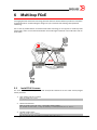
MULTI-HOP FCOE ................................................................................................. 56
6.1
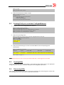
INSTALL FCOE LICENSE: .................................................................................................................... 56
6.2
ENABLING FCOE PORT ON INTERFACE TENGIGABITETHERNET ................................................................. 57
6.3
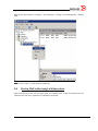
CREATING LUNS .............................................................................................................................. 57
6.4
DISCOVERING LUNS ......................................................................................................................... 57
6.5
STARTING FCOE TRAFFIC THROUGH A WINDOWS HOST .......................................................................... 58
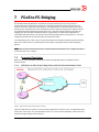
FCOE-TO-FC BRIDGING ........................................................................................ 60
7.1
7.1.1
VCS Fabrics as Fibre Channel Edge Fabrics with Fibre Channel Backbone Fabric ......... 60
7.1.2
Edge-to-Edge Sharing Using a Single Fibre Channel Backbone Fabric ............................ 61
7.1.3
Edge-to-Edge Sharing Ssing Dual Backbone ...................................................................... 61
7.2
8
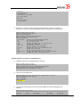
CONFIGURING FCOE-FC INTERCONNECT ............................................................................................. 62
7.2.1
Installing FCoE BASE License on VDX 6720/6730 ........................................................... 62
7.2.2
Viewing and Configuring FCoE ports on VDX 6720/6730 ................................................ 62
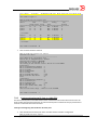
7.2.3
Viewing and Configuring FC Ports on a VDX 6730............................................................. 64
7.2.4
Defining and Enabling LSAN Zoning Configuration in a VCS Fabric ................................. 66
7.2.5
Creating and Enabling LSAN Zoning Configuration in Fibre Channel SAN Fabric ............ 67
7.2.6
Enabling Fibre Channel Routing (FCR) Service on FOS Switch ......................................... 68
7.2.7
Configuring Inter-fabric link (IFL) on the Fibre Channel Router (FCR) .............................. 68
7.2.8
Verifying Connectivity Between the Backbone and Edge Fabrics ..................................... 71
7.2.9
Verifying Devices are Correctly Shared Between Edge Fabrics ........................................ 75
HARDWARE RESILIENCY TESTING...................................................................... 78
8.1
9
SUPPORTED TOPOLOGIES .................................................................................................................. 60
POWER SUPPLY UNIT (PSU) AND FAN FAILOVER AND SERVICEABILITY....................................................... 78
SYSTEMS MANAGEMENT TESTING ..................................................................... 79
Strategic Solutions Lab
Page iii
9.1
OUT-OF-BAND MANAGEMENT VIA THE ETHERNET MANAGEMENT INTERFACE ............................................. 79
9.1.1
Configure a Static IPv4 Address on the Management Interface. ...................................... 79
9.1.2
Configure a Dynamic IPv4 Address Using DHCP: ............................................................... 79
9.1.3
Configure a Static IPv6 Address ......................................................................................... 79
9.1.4
Configure a Dynamic IPv6 Address ..................................................................................... 79
9.2
VCS FABRIC IP ADDRESS .................................................................................................................. 79
9.3
IN-BAND MANAGEMENT VIA VLAN, PHYSICAL OR PORT CHANNEL INTERFACES .......................................... 80
9.3.1
Configure In-band Management via VLAN ......................................................................... 80
9.3.2
Configure In-band Management via Physical Interface ..................................................... 80
9.3.3
Configure In-band Management via Port Channel ............................................................. 80
9.4
SUPPORTSAVE AUTOMATION ............................................................................................................... 80
9.4.1
Supportsave to a USB drive ................................................................................................ 80
9.4.2
Supportsave to an External Host ........................................................................................ 81
9.5
NETWORK TIME PROTOCOL (NTP) AND LOCAL CLOCK ........................................................................... 81
9.5.1
Verify NTP Operation............................................................................................................ 81
9.5.2
Verify Local Clock Operation ............................................................................................... 81
9.5.3
Configure Time Zone ........................................................................................................... 81
9.6
SYSLOG ........................................................................................................................................... 81
9.7
SFLOW ............................................................................................................................................ 81
9.8
SIMPLE NETWORK MANAGEMENT PROTOCOL (SNMP) ......................................................................... 82
9.9
HOST NAME..................................................................................................................................... 82
9.10 SWITCHED PORT ANALYZER (SPAN) ................................................................................................... 82
9.10.1
Bi-directional Mirroring ........................................................................................................ 82
9.10.2
Ingress Mirroring .................................................................................................................. 82
9.10.3
Egress Mirroring ................................................................................................................... 82
9.11 REMOTE MONITORING (RMON) ......................................................................................................... 83
9.12 RADIUS ......................................................................................................................................... 83
Strategic Solutions Lab
Page iv
9.13 TERMINAL ACCESS CONTROLLER ACCESS-CONTROL SYSTEM PLUS (TACACS+) ....................................... 83
9.14 ROLE-BASED ACCESS CONTROL (RBAC) ............................................................................................. 83
9.14.1
Create a New role ................................................................................................................ 84
9.14.2
Create a New User ............................................................................................................... 84
9.14.3
Create Rules for a Role ....................................................................................................... 84
9.15 LICENSING ....................................................................................................................................... 84
APPENDIX ................................................................................................................... 85
Strategic Solutions Lab
Page v
Introduction
This document provides a series of test cases that demonstrate and validate features and functions
provided in Brocade VDX Switches running Brocade Network Operating System (NOS). VDX switches
include Brocade VCS Fabric technology that removes many of the limitations facing datacenter
networks supporting virtualization, cloud computing and ever larger amounts of data storage.
The test cases demonstrate the benefits of a VCS Fabric including improved performance, availability,
and simple configuration and management, and also show interoperability of a VCS Fabric with classic
Ethernet environments using Spanning Tree Protocol (STP).
For environments where Fiber Channel over Ethernet (FCoE) is used, there are configuration and test
cases covering FCoE and FCoE to Fibre Channel connectivity.
The commands listed in the various test cases are provided as working examples. Other NOS
commands may be accomplish similar test results. Test cases do not cover every configuration step
required to run a particular test, but show key commands with sufficient description to create a
complete test case . It is expected that the engineer conducting testing will have a working knowledge
of Brocade VDX Switches, Brocade NOS and have access to the latest Brocade Network Operating
System Administrator Guide.
The following documents are valuable resources for the designer. In addition, any Brocade release
notes that have been published for NOS, FOS the Fibre Channel switching and VDX Switch products
should be at hand before conducting these test cases.
Related Documents
References
• Brocade Network OS (NOS) Administrator Guide, v3.0.1
• Brocade Fabric OS Administrator Guide, R7.0.1
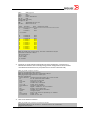
Document History
Date
2013-02-27
Version
1.0
Strategic Solutions Lab
Description
Initial Version with NOS 3.0.1 and FOS 7.0.1
Page 1
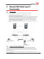
1
Brocade VCS Fabric Layer 2
Functionality
1.1
Topology used
Below is the test configuration. It consists of the following devices and constraints.
•
•
•
•
•
1.2
Three Brocade VDX 6720-24 switches running either NOS v2.1.1 or v3.0.
Only Layer 2 connectivity tests are provided
Connectivity to a core consisting of a pair of Cisco Nexus 7000 is tested. The two Nexus 7000
use virtual Port Channel (vPC) so the Nexus 7000 appear as a single logical Layer 2 switch.
The test cases are not restricted to specific servers or OS versions. Typically more than one
server is connected to the fabric if VM mobility and the VCS Fabric Automated Migration of
Port Profiles (AMPP) feature is being tested.
Servers are configured with virtual machines (VM) that are used to create traffic during the
tests.
Configure VCS ID and RBridge IDs
In a VCS Fabric, every member switch has a unique identifier called Routing Bridge (RBridge) ID.
Additionally, every switch in the same VCS Fabric must have the same VCS Fabric ID or VCS ID. The
only prerequisites for two VDX switches to connect and form a fabric are they have the same VCS ID
and unique RBridge IDs.
The first task will be to make sure that the three VDX switches are properly configured to form a fabric.
Strategic Solutions Lab
Page 2
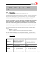
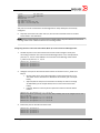
Configure a unique RBridge ID on each RBridge, with the same VCS ID, and reboot the switches:
RB1# vcs rbridge-id 1 vcs-id 1 enable
RB1# fastboot
RB2# vcs rbridge-id 2 vcs-id 1 enable
RB2# fastboot
RB3# vcs rbridge-id 3 vcs-id 1 enable
RB3# fastboot
1.3
Automatic Creation of VCS Fabric
Once the RBridge and VCS IDs have been configured for every fabric member, we just need to connect
the cables between them and the fabric will automatically form. All members will automatically be
discovered along with the routes between each member in the fabric. The following tests will
demonstrate how the fabric will automatically form when connecting the cables between the VDX
switches.
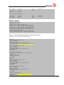
Log in to RB1 and demonstrate fabric comprises a single unit:
RB1# show fabric all
RB1# fastboot
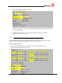
Enable the link between RB1 and RB2:
RB1# conf t
RB1# int te 1/0/1
RB1# no shutdown
RB2# conf t
RB2# int te 2/0/1
RB2# no shutdown
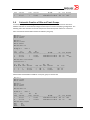
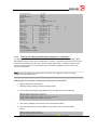
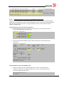
Show that the fabric has formed with two VDX switches:
RB1# show fabric all
VCS Id: 1
Config Mode: Local-Only
Rbridge-id
WWN
IP Address
Name
---------------------------------------------------------------------------1
10:00:00:05:33:5F:E2:7F
192.168.222.123
>"RB1"*
2
10:00:00:05:33:72:6D:A3
192.168.222.124
"RB2"
RB1# show fabric route topology
Total Path Count: 1
Src
Dst
Out
Out
Nbr
Nbr
RB-ID RB-ID Index Interface
Hops Cost Index Interface
BW
Trunk
----------------------------------------------------------------------------------1
2
1
Te 1/0/1
1
500
1
Te 2/0/1
10G
Yes
RB1# show fabric isl
Rbridge-id: 1
Src
#ISLs: 1
Src
Strategic Solutions Lab
Nbr
Nbr
Page 3
Index
Interface
Index
Interface
Nbr-WWN
BW
Trunk Nbr-Name
---------------------------------------------------------------------------------------------1
Te 1/0/1
1
Te 2/0/1
10:00:00:05:33:72:6D:A3
10G
Yes
"RB2"
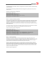
1.4
Automatic Creation of ISLs and Trunk Groups
A VCS Fabric simplifies the configuration and operation of Layer 2 Ethernet networks. New links
between switches are automatically configured and require no manual simplifying configuration. The
following tests show how ISLs and Trunk Groups form automatically when cables are connected.
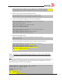
Add a second link between RB1 and RB2 on different port group:
RB1# conf t
RB1# int te 1/0/13
RB1# no shutdown
RB2# conf t
RB2# int te 2/0/13
RB2# no shutdown
RB1# show fabric isl
Rbridge-id: 1
#ISLs: 2
Src
Src
Nbr
Nbr
Index
Interface
Index
Interface
Nbr-WWN
BW
Trunk Nbr-Name
---------------------------------------------------------------------------------------------1
Te 1/0/1
1
Te 2/0/1
10:00:00:05:33:72:6D:A3
10G
Yes
"RB2"
13
Te 1/0/13
2
Te 2/0/13
10:00:00:05:33:72:6D:A3
10G
Yes
"RB2"
RB1# show fabric route topology
Total Path Count: 2
Src
Dst
Out
Out
Nbr
Nbr
RB-ID RB-ID Index Interface
Hops Cost Index Interface
BW
Trunk
----------------------------------------------------------------------------------1
2
1
Te 1/0/1
1
500
1
Te 2/0/1
10G
Yes
1
2
13
Te 1/0/13
1
500
13
Te 2/0/13
10G
Yes
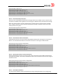
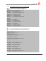
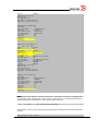
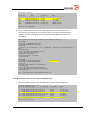
Add third link between RB1 and RB2 on same port group as the first link:
RB1# conf t
RB1# int te 1/0/2
RB1# no shutdown
RB2# conf t
RB2# int te 2/0/2
RB2# no shutdown
RB1# show fabric isl
Rbridge-id: 1
#ISLs: 3
Src
Src
Nbr
Nbr
Index
Interface
Index
Interface
Nbr-WWN
BW
Trunk Nbr-Name
---------------------------------------------------------------------------------------------1
Te 1/0/1
1
Te 2/0/1
10:00:00:05:33:72:6D:A3
20G
Yes
"RB2"
13
Te 1/0/13
2
Te 2/0/13
10:00:00:05:33:72:6D:A3
10G
Yes
"RB2"
RB1# show fabric islports
Name:
RB1
Type:
95.2
State:
Online
Strategic Solutions Lab
Page 4
Role:
Fabric Principal
VCS Id:
1
Config Mode:Local-Only
Rbridge-id: 1
WWN:
10:00:00:05:33:5f:e2:7f
FCF MAC:
00:05:33:5f:e2:7f
Index
Interface
State
Operational State
===================================================================
1
Te 1/0/1
Up
ISL 10:00:00:05:33:72:6d:a3 "RB2" (downstream) (Trunk Primary)
2
Te 1/0/2
Up
ISL (Trunk port, Primary is Te 1/0/1 )
3
Te 1/0/3
Down
4
Te 1/0/4
Down
5
Te 1/0/5
Down
6
Te 1/0/6
Down
7
Te 1/0/7
Down
8
Te 1/0/8
Down
9
Te 1/0/9
Down
10
Te 1/0/10
Down
11
Te 1/0/11
Down
12
Te 1/0/12
Down
13
Te 1/0/13
Down ISL 10:00:00:05:33:72:6d:a3 "RB2" (Trunk Primary)
14
Te 1/0/14
Down
15
Te 1/0/15
Down
16
Te 1/0/16
Down
17
Te 1/0/17
Down
18
Te 1/0/18
Down
19
Te 1/0/19
Down
20
Te 1/0/20
Down
21
Te 1/0/21
Down
22
Te 1/0/22
Down
23
Te 1/0/23
Down
24
Te 1/0/24
Down
RB1# show fabric route topology
Total Path Count: 2
Src
Dst
Out
Out
Nbr
Nbr
RB-ID RB-ID Index Interface
Hops Cost Index Interface
BW
Trunk
----------------------------------------------------------------------------------1
2
1
Te 1/0/1
1
500
1
Te 2/0/1
20G
Yes
1
2
13
Te 1/0/13
1
500
13
Te 2/0/13
10G
Yes
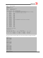
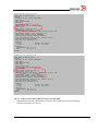
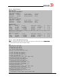
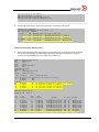
Add a link from RB3 to both RB1 and RB2, and verify the fabric updates the topology automatically:
RB1#
RB1#
RB1#
RB1#
RB1#
conf t
int te 1/0/4
no shutdown
int te 1/0/5
no shutdown
RB2#
RB2#
RB2#
RB2#
RB2#
conf t
int te 2/0/4
no shutdown
int te 2/0/5
no shutdown
RB3#
RB3#
RB3#
RB3#
RB3#
RB3#
RB3#
RB3#
RB3#
conf t
int te 3/0/1
no shutdown
int te 3/0/2
no shutdown
int te 3/0/3
no shutdown
int te 3/0/4
no shutdown
RB1# show fabric all
Strategic Solutions Lab
Page 5
VCS Id: 1
Config Mode: Local-Only
Rbridge-id
WWN
IP Address
Name
---------------------------------------------------------------------------1
10:00:00:05:33:5F:E2:7F
192.168.222.123
>"RB1"*
2
10:00:00:05:33:72:6D:A3
192.168.222.124
"RB2"
3
10:00:00:05:33:CD:32:B5
192.168.222.132
"RB3"
RB1# show fabric route topology
Total Path Count: 2
Src
Dst
Out
Out
Nbr
Nbr
RB-ID RB-ID Index Interface
Hops Cost Index Interface
BW
Trunk
----------------------------------------------------------------------------------1
2
1
Te 1/0/1
1
500
1
Te 2/0/1
20G
Yes
1
2
13
Te 1/0/13
1
500
13
Te 2/0/13
10G
Yes
1
3
4
Te 1/0/4
1
500
4
Te 3/0/4
20G
Yes
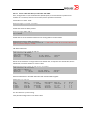
1.5
MAC Address Learning
A feature of a VCS Fabric is the distributed control plane connecting all switches in the fabric. The
Ethernet name server (eNS) is a distributed service that maintains information about the MAC address
attached of all devices connected to the fabric and the switch port the devices is connected to. The
following tests will demonstrate that the MAC address table is distributed across all switches in the
fabric.
Verify that the MAC address table is empty on all RBridges in the fabric. At this point, since we haven’t
initiated any traffic across the fabric, there should be no MAC entries.
RB1# show mac-address-table
RB2# show mac-address-table
RB3# show mac-address table
Enable the ports on RB1 and RB2 connected to the servers and configure them for access mode with
VLAN 1.
RB1#
RB1#
RB1#
RB1#
RB1#
RB1#
conf t
int te 1/0/8
switchport
switchport mode access
switchport access vlan 1
no shutdown
RB2#
RB2#
RB2#
RB2#
RB2#
RB2#
conf t
int te 2/0/8
switchport
switchport mode access
switchport access vlan 1
no shut
Ping from VM1 to VM2 to create a traffic flow through the network, and then check the MAC address
table on each VDX switch.
RB1# show mac-address-table
Strategic Solutions Lab
Page 6
RB2# show mac-address-table
RB3# show mac-address table
Verify that the MAC addresses of VM1 and VM2 have been updated on RB3, even if it didn’t
participate in the forwarding of frames between the two virtual machines.
1.6
Shortest-path Forwarding, ECMP and Load Balancing
Brocade VCS Fabric is based on TRILL and Fibre Shortest Path First (FSPF) to provide shortest-path
forwarding between switches in the fabric. This provides equal-cost multipath (ECMP) forwarding when
there are two or more equal-cost Layer 2 paths between switches. In addition, Brocade hardware
creates ISL Trunks that frame stripe all traffic across links in the ISL Trunks. This provides the highest
utilization of links in the ISL Trunk.
Verify there are two equal-cost paths between RB1 and RB2, and one dual-hop path through RB3.
RB1# show fabric route topology
Generate traffic between VM1 on RB1 and VM2 on RB2. To better show traffic load balancing across
equal-cost paths, use a traffic generation tool such as IOMeter to create traffic between the two VMs
instead of ping. Verify the traffic uses the shortest path(s) in the fabric and that it is balanced across
both equal-cost paths and weighted based on each path’s bandwidth:
RB1# show interface | include Output
RB1# show interface | include Input
1.7
Verify Traffic Flows When Links and ISL Trunks Fail
A VCS Fabrics is self-healing. When an ISL Trunk link fails, traffic is automatically and non-disruptively
re-distributed among the remaining links in the trunk without administrator intervention. If a complete
path fails, the fabric re-routes all traffic to the remaining least-cost paths in the. These actions are subsecond and do not generally disrupt user traffic.
With traffic running between the two VMs, remove a link in an ISL Trunk group between RB1 and RB2,
to demonstrate that no traffic interruption has occurred, and traffic automatically fails over to
remaining links in the trunk group.
RB1#
RB1#
RB1#
RB1#
conf t
int te 1/0/2
shutdown
exit
RB1# show interface | include Input
RB1# show interface | include Output
Next, remove a link not in an ISL Trunk which is a separate path between two to demonstrate how
traffic fails over to remaining link between RB1 and RB2.
RB1#
RB1#
RB1#
RB1#
conf t
int te 1/0/13
shutdown
exit
Strategic Solutions Lab
Page 7
RB1# show interface | include Input
RB1# show interface | include Output
Finally, remove the last link between RB1 and RB2, and verify that traffic fails over to the two-hop path
through RB3 which is now the least-cost path in the fabric between RB1 and RB2.
RB1#
RB1#
RB1#
RB1#
conf t
int te 1/0/1
shutdown
exit
RB1# show interface | include Input
RB1# show interface | include Output
Restore all links between RB1 and RB2, and verify that traffic re-routes to the shortest path and is
appropriately load-balanced.
RB1#
RB1#
RB1#
RB1#
RB1#
RB1#
RB1#
RB1#
conf t
int te 1/0/1
no shutdown
int te 1/0/2
no shutdown
int te 1/0/13
no shutdown
exit
RB1# show interface | include Input
RB1# show interface | include Output
Note that all of this has happened without any manual intervention on the part of the network
administrator.
1.8
Ethernet Fabric Vs. Spanning Tree Protocol (STP)
These tests show the performance advantage of a VCS Fabric vs. STP. The topology is a full mesh
network. The test uses industry standard RFC 2889 Fully Meshed test cases to measure throughput,
and also the Lippis’ Cloud Simulation Test to measure latency for cloud application traffic.
The tests are performed using Ixia XM12 chassis running IxNetwork Version: 5.70.352.8 and
IxAutomate 6.90.102.3 GA-SP1.
The exact same tests are run once while switches are in VCS Fabric and then again while switches are
in standalone mode with Spanning Tree protocol enabled.
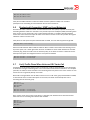
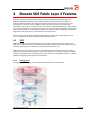
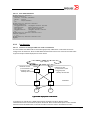
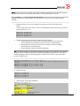
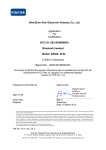
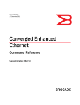
The following diagram shows the four VDX 6720 switches in VCS Fabric mode in a full mesh topology
with eight IXIA 10Gbps testing ports.
Strategic Solutions Lab
Page 8
Four VDX 6720 Switches, Full Mesh VCS Fabric
VDX6720
10.20.55.77
10G
VDX6720
10.20.55.78
IXIA 1.4.2
IXIA 1.4.6
VDX6720
10.20.55.177
IXIA 1.4.4
IXIA 1.4.8
10
G
IXIA 1.4.1
IXIA 1.4.5
IXIA 1.4.3
IXIA 1.4.7
VDX6720
10.20.55.79
10G
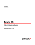
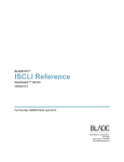
The following diagram shows the effective topology when the four VDX switches operate as standalone switching with STP used for frame forwarding. The red dotted line indicates paths that STP
blocks and disables to prevent loops.
Four VDX 6720 Switches, Full Mesh with RSTP
IXIA 1.4.1
IXIA 1.4.5
10G
VDX6720
10.20.55.78
IXIA 1.4.2
IXIA 1.4.6
VDX6720
10.20.55.177
IXIA 1.4.4
IXIA 1.4.8
10
G
VDX6720
10.20.55.77
IXIA 1.4.3
IXIA 1.4.7
VDX6720
10.20.55.79
(STP ROOT)
10G
Spanning tree disabled links
Throughput Performance Test
Throughput describes the highest rate at which a switch forwards traffic with zero frame loss. It’s a
critical metric as even a single dropped frame can have adverse effects on application performance.
This test measures throughput for unicast traffic, as defined in RFC 2889. Tests involved a fully
meshed pattern of traffic between 8 switch ports for duration of 20 seconds per iteration, using
IxAutomate.
Strategic Solutions Lab
Page 9
The RFC-2889 Fully Meshed Throughput Test determines the total number of frames that the Device
Under Test(DUT) can handle when it receives frames on all ports. All ports transmit and receive traffic
at a specified transmission rate such that each switch interface transmits and receives frames
to/from all of the other switches and their interfaces. Each switch port being tested sends frames to
all other ports in an evenly distributed, round-robin type fashion.
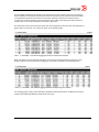
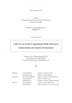
The VCS Fabric mode network achieves 100% line rate throughput for all frame sizes that 256 bytes or
greater with no frame loss. The results are shown in the following table.
Table – 1: RFC2889 – Fully Meshed Aggregate Results for VCS Fabric Network
When the switches are reconfigured with RSTP, the maximum throughput without frame loss is only
57.8% of full line rate using the same testing ports. The results are shown in the following table.
Table – 2: RFC2889 – Fully Meshed Aggregate Results for Spanning-Tree Network
The following graphs compare the VCS Fabric and RSTP network performance at different frame sizes
using the RFC 2889 Fully Meshed performance test cases.
Strategic Solutions Lab
Page 10
Public Cloud Simulation Test
The cloud simulation test determines the performance of the DUT when forwarding a mixture of northsouth and east-west traffic typical of cloud computing applications. Test parameters include traffic
type, traffic rate, frame size, offered traffic behavior and traffic mesh.
The test measures the throughput, latency, jitter and frame loss on a per application traffic type basis
across a set of 8 port topologies. The following traffic types were tested: web (HTTP), database-server,
server-database, iSCSI storage-server, iSCSI server-storage, client-server plus server-client.
The north-south client-server traffic simulates Internet browsing; the database traffic simulates serverserver lookup and data retrieval, while the storage traffic simulates IP-based IO. When all traffic types
are instantiated, the throughput, latency, jitter and frame loss pare measured for each traffic type.
The following tables show the result of the cloud simulation test for a VCS Fabric and Spanning-Tree
configured network.
Traffic Item
Tx Frames
Rx Frames
Loss
%
StoreForward Avg
Latency (ns)
StoreForward
Min Latency
(ns)
StoreForward
Max
Latency (ns)
First
TimeStamp
Last
TimeStamp
NS-Client_to_Server
221,941,19
0
221,941,19
0
0
2,244
80
17,080
00:03.2
02:52.8
NS-Server_to_Client
53,308,309
53,308,309
0
2,951
60
196,360
00:03.2
02:52.8
EW-HTTP
320,535,10
4
320,535,10
4
0
4,580
60
219,200
00:03.2
02:52.8
EWServer_to_Database
1,033,921,1
52
1,033,921,1
52
0
1,846
1,080
10,980
00:03.2
02:52.8
EWDatabase_to_Server
64,306,383
64,306,383
0
7,383
0
216,880
00:03.2
02:52.8
iSCSIServer_to_Storage
27,391,296
27,391,296
0
904
0
10,580
00:03.2
02:52.8
iSCSIStorage_to_Server
13,695,648
13,695,648
0
5,879
0
54,720
00:03.2
02:52.8
Strategic Solutions Lab
Page 11
Lippis’ Cloud Test Result for VCS Fabric Network
Traffic Item
Tx Frames
Rx Frames
Loss
%
StoreForward Avg
Latency (ns)
StoreForward
Min
Latency
(ns)
StoreForward
Max Latency
(ns)
First
TimeStamp
Last
TimeStamp
NS-Client_to_Server
177,428,68
6
177,428,62
9
0
58,027
860
106,460
00:03.2
02:18.8
NS-Server_to_Client
42,616,800
42,616,770
0
83,870
40
238,840
00:03.2
02:18.8
EW-HTTP
242,019,30
8
242,019,17
3
0
69,538
40
321,080
00:03.2
02:18.8
EWServer_to_Database
734,761,64
8
734,761,34
0
0
55,922
1,040
98,120
00:03.2
02:18.8
EWDatabase_to_Server
46,516,783
46,516,730
0
81,356
0
230,920
00:03.2
02:18.8
iSCSIServer_to_Storage
19,465,773
19,465,764
0
55,037
0
99,740
00:03.2
02:18.8
iSCSIStorage_to_Server
10,948,850
10,948,842
0
82,636
0
235,260
00:03.2
02:18.8
Lippis’ Cloud Test Result for SpanningSpanning-Tree Network
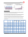
The following graph compares the average latency for cloud computing applications when using VCS
Fabric and STP. The STP network has substantially higher latency than a VCS Fabric.
Strategic Solutions Lab
Page 12
Based on these results for a four switch full mesh network, throughput of a VCS Fabric exceeds an STP
network at close to 2:1 margin. In public cloud application latency testing, STP network latency is 50
to 60 times greater than VCS Fabric latency. This is an enormous advantage for a VCS Fabric.
It is clear that VCS Fabric technology employs superior routing, switching and load balancing high
performance with very low latency in a mesh network topology.
1.9
Ethernet LAG Vs. Brocade ISL Trunking
Link aggregation bundles multiple physical Ethernet links into a single logical link, or trunk. The logical
trunk is called a Link Aggregation Group (LAG).
Brocade ISL Trunking is one of the Brocade ASIC features that bundles multiple Inter-Switch Links
(ISL) into a single logical ISL trunk. When a switch is connected to a VCS Fabric, ISLs automatically
form between directly connected switches. When more than one ISL connects two switches, a Brocade
ISL Trunk can automatically form if the ISLs are in the same ASCI Port Group boundary in each switch-.
Brocade ISL Trunking is a true plug and play feature that does not require special configuration
procedures or user intervention.
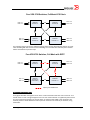
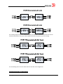
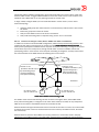
LAG and Brocade ISL Trunking appear similar, but very different in how they are implemented and how
they perform. In the diagram below, two switches are connected with multiple links but use LAG
Strategic Solutions Lab
Page 13
The following diagram shows two VDX6720 switches in VCS Fabric mode connected with two or three
10G links Brocade ISL Trunk and six IXIA 10Gbps tester ports connections use in the testing.
For the following tests, the same traffic flows are used with each configuration.
Comparing Configuration and Management
Strategic Solutions Lab
Page 14
Configuring LAG involves logging into both switches and going through several configuration steps as
shown below. For VCS Fabrics, the only action required to establish a Brocade ISL Trunk is connecting
cables to the two switches that are within the same Port Group in each switch. No additional
configuration is required.
Configuring LAG (for 2 members)
Configuring ISL Trunking (for up to 8 members)
Execute the following commands on one switch:
•
•
•
•
•
•
•
•
•
•
•
•
•
•
•
configure terminal
interface port-channel 1
switchport
switchport mode trunk
switchport trunk allowed vlan all
qos flowcontrol tx on rx on
mtu 9208
no shutdown
interface tengigabitethernet 1/0/5
channel-group 1 mode active type standard
no shutdown
interface tengigabitethernet 1/0/6
channel-group 1 mode active type standard
no shutdown
exit
Absolutely no configuration required.
Total commands: 0
Repeat same commands on other end switch.
Total commands: 30
Link Utilization
Utilization and Load Balancing
To avoid too much traffic on a given link in a LAG, the hashing algorithm has to have enough entropy
for the various traffic flows so traffic will be allocated without exceeding the bandwidth of any single
link In the test case below, three traffic flows from port 1, 2 and 3 are hashed to a single link in the
LAG causing unexpected congestion and a bottleneck to occur. Changing how the hash allocates
traffic to links requires manual configuration changes, and in some configurations, it can be hard or
impossible to avoid congestion on a link in the LAG. Said differently, LAG with hashing can not ensure
full link utilization under arbitrary traffic flows.
Strategic Solutions Lab
Page 15
Brocade ISL trunks do not use hashing to balance traffic across the individual ISL links in an ISL trunk.
Frames are sprayed across all links in the ISL Trunk regardless of the flow the frame belongs to. The
ASICs ensure in order delivery of all frames and that jitter is within acceptable limits. The result is
automatic, near perfect load balancing across all links in an ISL Trunk with any arbitrary combination
of traffic flows.
The following snapshot from the IxNetwork test shows congestion on switch port-5 in the LAG setup.
The 64 and 1518 byte traffic flows coming from port-1 and 2 have massive frame loss although the
traffic generator is operating at 50% of line rate for these ports. With the Brocade ISL Trunk, all
available links are fully utilized for the 64, 1518, and 9000 byte flows allowing the ISL Trunk to 100%
throughput (i.e. 50% of the line rate or 5Gbps from each port) without frame loss.
IXIA 1.4.1
<=> 1.4.4
Traffic Item
Tx Frame
Rate
Rx Frame
Rate
Tx Frames
Rx Frames
Frames Delta
Loss %
LAG:
14,880,953
3,926,472
991,581,400
261,637,212
729,944,188
73.61
812,744
598,405
54,156,592
39,874,342
14,282,250
26.37
138,581
138,581
9,234,240
9,234,234
6
0.00
14,880,953
14,880,956
991,581,399
991,581,340
59
0.00
812,744
812,744
54,156,592
54,156,588
4
0.00
138,581
138,581
9,234,240
9,234,238
2
0.00
64 Bytes
IXIA 1.4.2
<=> 1.4.5
LAG:
1518 Bytes
IXIA 1.4.3
<=> 1.4.6
LAG:
9000 Bytes
IXIA 1.4.1
<=> 1.4.4
ISL Trunk:
64 Bytes
IXIA 1.4.2
<=> 1.4.5
ISL Trunk:
1518 Bytes
IXIA 1.4.3
<=> 1.4.6
ISL Trunk:
9000 Bytes
Strategic Solutions Lab
Page 16
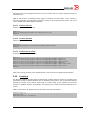
Flow control can be used to prevent frame loss for certain traffic flows when congestion occurs. The
following table shows the effective data rate for each traffic flow when using flow control. When using
LAG, all three flows experience a bottleneck with the 64 bytes flow only achieving 36.9% of the desired
flow rate, the 1518 byte flow achieves 76% of desired rate, and the 9000 byte flow achieves 87.1% of
the desired flow..
For the Brocade ISL Trunk configuration, all three flows achieve 100% of the desired flow rate.
IXIA 1.4.1 <=>
IXIA 1.4.4
Traffic Item
Intended
Frame Rate
Effective
Frame Rate
Loss %
Effective
Rate %
Blocking /
Pausing %
LAG:
14,880,953.00
5,491,509.00
0.00
36.90
63.10
812,744.00
617,778.50
0.00
76.01
23.99
138,581.00
120,703.00
0.00
87.10
12.90
14,880,953.00
14,880,953.00
0.00
100.00
0.00
812,744.00
812,744.00
0.00
100.00
0.00
138,581.00
138,581.00
0.00
100.00
0.00
64 Bytes
IXIA 1.4.2 <=>
IXIA 1.4.5
LAG:
1518 Bytes
IXIA 1.4.3 <=>
IXIA 1.4.6
LAG:
9000 Bytes
IXIA 1.4.1 <=>
IXIA 1.4.4
ISL Trunk:
64 Bytes
IXIA 1.4.2 <=>
IXIA 1.4.5
ISL Trunk:
1518 Bytes
IXIA 1.4.3 <=>
IXIA 1.4.6
ISL Trunk:
9000 Bytes
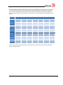
Link Resiliency
To test link resiliency and measure how fast a link can failover, the second topology with three links in
a trunk can be used. One link in the trunk shut off with bi-directional traffic flows of 64, 1518, and
9000 bytes using the the trunk at a rate of 5 Gbps each. Using IxNetwork statistics, the failover time is
measured for each traffic flow.
Strategic Solutions Lab
Page 17
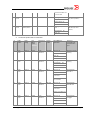
The flowing table shows data collected from 7 trial runs when failing any one of the links in the trunk.
The test results are for both a LAG and Brocade ISL Trunk configuration. The link failover required for
LAG is over 50 milliseconds while the link failover required for the Brocade ISL Trunk is no greater
than 7.22 micro seconds. The LAG failover is on the order of 7 times as long as the Brocade ISL Trunk
failover.
Failover Time (us)
Traffic Item
Trial - 1
Trial - 2
Trial - 3
Trial - 4
Trial - 5
Trial - 6
Trial - 7
LAG:
64 Bytes
79.97
45,475.45
49,576.06
50,204.51
68.14
79.43
79.23
LAG:
1518 Bytes
50,127.72
166.10
0.00
0.00
49,917.32
50,259.37
49,705.69
LAG:
9000 Bytes
50,129.53
93.81
79.38
79.38
49,826.46
50,266.63
49,573.90
ISL Trunk:
64 Bytes
1.21
5.38
1.34
1.08
1.88
3.29
1.61
ISL Trunk:
1518 Bytes
1.23
1.23
2.46
1.23
0.00
0.00
4.92
ISL Trunk:
9000 Bytes
0.00
7.22
0.00
7.22
7.22
0.00
0.00
These tests demonstrate the superiority of a Brocade ISL Trunk compared to LAG for link utilization,
latency and link resiliency.
Strategic Solutions Lab
Page 18
2
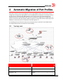
Automatic Migration of Port Profiles
VCS Fabric includes the Automatic Migration of Port Profile (AMPP) feature that automates network
configuration changes when VM migration occurs. An AMPP policy is defined for a Port Group and then
the Port Group is associated with MAC addresses. This means security and network policies are
defined once and are enforced fabric wide. They are not limited to a single port on a single switch. In a
dynamic environment with VM migration, AMPP the policies in the physical network always apply to the
VM MAC no matter what port on a VCS Fabric that traffic appears on.
The following tests are based on the test plan used by Brocade for verification of the AMPP feature.
The diagram below shows an example of the test topology.
2.1
Topology used
Platforms prominently used
Description
VDX 6270 – 24/VDX6730 - 24
VDX with 24 10G ports
VDX 6270 – 60/VDX6730 – 60
VDX with 60 10G ports
VDX 6210 – 48
VDX with 48 1G ports (server facing) and 6 10G
uplinks
Strategic Solutions Lab
Page 19
2.2
AMPP Test Considerations
Any explicit reference to VDX 87xx and NOS 3.0.0 is hardware/software currently under test – not yet
fully qualified. Below are considerations to keep in mind when testing the AMPP feature.
a) The AMPP feature can be tested with all VDX products – VDX-6720 (both 24 and 60 ports),
VDX6730 (both 24 and 60 ports), VDX6710 & VDX 8710 (4 slot and 8 slot).
b) Refer to release notes for full list of features and supported scalability values.
c) Capability to provision VLAN allow/disallow ability, permit/deny data traffic using
standard/extended ACLs and provision traffic scheduling/prioritization using Layer 2 QoS
capabilities – all built into a ‘port-profile’.
d) Special capability to give different ACL treatments to different MACs on same interfaces
(physical/LAG) at the same time on VDX 87xx (feature under test in NOS3.0.0).
e) Port-profile(s) can follow the MAC address(s) associated to it when the Virtual Machine
migrates (VMotion) from one physical interface to another.
f) User can allow traffic from non-profiled MACs through a global knob (feature under test in
NOS3.0.0).
g) The port-profile will not get activated until all the dependencies are resolved.
h) The fabric can allow multiple port-profiles to be applied on a single port, but in case of conflict
then the application of later port-profile will fail with appropriate RASLOG.
i) User can control the application of port-profile by activating or deactivating the port-profile.
j) Key feature added on NOS2.1 – Network OS – vCenter Integration (aka, VMWare Network
Automation).
2.3
Setup and Verify Procedure: Create, Associate, Activate and
Apply a Port Profile.
a) Create a port-profile:
VDX
VDX
VDX
VDX
(config)# port-profile
(config-vlan-profile)#
(config-vlan-profile)#
(config-vlan-profile)#
test_profile
switchport
switchport mode access
switchport access vlan 1
b) Activate the port-profile:
VDX (config)# port-profile test_profile activate
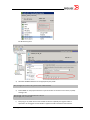
c) Identify the MAC address of a Virtual Machine –
For VMWare vCenter:
Strategic Solutions Lab
Page 20
For Microsoft Hyper-V:
d) Associate VM MAC addresses to the appropriate port-profile.
VDX (config)# port-profile test_profile static 0005.1ed7.8def
e) Enable AMPP on the physical interface or port-channel that connects to the server (say ESX)
hosting a VM.
VDX(config)# interface tengigabitethernet 236/0/8
VDX(config)# port-profile-port
f)
Start ping or any traffic. Since a Port Profile has Access capability, the ingress traffic is
expected to be untagged. The Port Profile is applied to traffic received on this interface.
Strategic Solutions Lab
Page 21
VDX# show port-profile name test_profile status
Port-Profile
PPID
Activated
Test_profile
2
Yes
VDX#
2.4
Associated MAC
0005.1ed7.8def
Interface
Te 236/0/8
Validation of Port Profile Capabilities:VLAN, ACL, QoS and FCoE
port
Please refer section 3.1.3 for commands to create/activate/associate port-profiles.
2.4.1
Validation of VLAN Configuration
The following tests verifiy the ‘switchport’ capabilities enabled on a physical port once a Port Profile is
successfully applied.
Setup: Use Topology in section 3.1.1
Use following commands to change VLAN allow/disallow combinations –
Example: To set a port-profile for accepting untagged frames alone –
VDX_49113(config)# port-profile test_profile
VDX_49113(config-port-profile-test_profile)# vlan-profile
VDX_49113(config-vlan-profile)# switchport
VDX_49113(config-vlan-profile)# switchport mode access
VDX_49113(config-vlan-profile)#
Set a VLAN profile to a desired configuration – Access, Trunk (allow/add/remove etc.)
VDX_49113(config)# port-profile test_profile
VDX_49113(config-port-profile-test_profile)# vlan-profile
VDX_49113(config-vlan-profile)# switchport ?
Possible completions:
access
Set the Layer2 interface as Access
mode
Set mode of the Layer2 interface
trunk
Set the Layer2 interface as trunk
<cr>
VDX_49113(config-vlan-profile)# switchport trunk ?
Possible completions:
allowed
Set the VLANs that will Xmit/Rx through the Layer2 interface
native-vlan
Set the native VLAN to classify untagged traffic.
VDX_49113(config-vlan-profile)# switchport trunk allowed ?
Possible completions:
vlan
VLAN(s) that will be added/removed
VDX_49113(config-vlan-profile)# switchport trunk allowed vlan ?
Possible completions:
add
Allow these VLANs to Xmit/Rx through the Layer2 interface
all
Allow all VLANs to Xmit/Rx through the Layer2 interface
except
Allow all VLANs except this vlan range to Xmit/Rx through the
Layer2 interface
none
Allow no VLANs to Xmit/Rx through the Layer2 interface
remove
Remove a VLAN range that Xmit/Tx through the Layer2 interface
VDX_49113(config-vlan-profile)# switchport trunk allowed vlan
Repeat the test for a VLAN Profile with:
1. Access versus Trunk
2. Various types of ingress traffic versus VLAN configuration on port-profile.
Strategic Solutions Lab
Page 22
See the Appendix for detailed steps .
Repeat both tests for:
a) Tengigabit Ethernet
b) Gigabit Ethernet
c) LAG, VLAG (both 1G and 10G)
2.4.2
Validation of ACL Configuration
Setup the following
1. Create a port-profile with desired VLAN configuration using Section 3.1.3.
2. Create an extended Layer 2 MAC ACL using following procedure.
VDX_49113(config)# mac access-list extended acl1
VDX_49113(conf-macl-ext)# permit host 0050.0000.0001 host 0050.0000.0004 count
VDX_49113(conf-macl-ext)# deny host 0050.0000.0001 host 0050.0000.0003 count
3. Create a security profile and attach the above access list to it
VDX_49113(config)# port-profile test_profile
VDX_49113(config-port-profile-test_profile)# security-profile
VDX_49113(config-security-profile)# mac access-group acl1 in
NOTE: Make sure to associate the MAC addresses defined in Security Profile ACL to the port-profile
(Section 3.1.3 step d)
4. Send the traffic and verify the application of the access list using following command
VDX_49113# show statistics access-list mac acl1 in
NOTE: User should see acl1 is getting applied through the port-profile
Repeat above tests for
a) Tengigabit Ethernet
b) Gigabit Ethernet
c) LAG, VLAG (both 1G and 10G)
2.4.3
Validation of QoS
Setup the following
1. Create a port-profile with the desired VLAN configuration using Section 3.1.3.
2. Create a QoS profile using following procedure
VDX_49113(config)# port-profile test_profile
VDX_49113(config-port-profile-test_profile)# qos-profile
3. The following “qos” and “cee” options are available under the QoS profile
Strategic Solutions Lab
Page 23
VDX_49113(config-qos-profile)# qos ?
Possible completions:
cos
Configure default Class of Service (CoS)
cos-mutation
Configure CoS-to-CoS mutation (Max Size - 32)
cos-traffic-class
Configure CoS-to-Traffic Class map (Max Size - 32)
flowcontrol
IEEE 802.3x Flow Control
trust
Configure QoS Trust
VDX_49113(config-qos-profile)# cee ?
Possible completions:
<string>
NOTE: User needs to configure appropriate cos-mutation maps, cos-traffic-class maps and cee maps before
configuring them under the qos sub profile. Please refer to the NOS admin guide for exact configuration
steps.
4.
Send the profiled traffic and verify QoS is being applied using the following commands
VDX_49113# show qos queue int t x/y/z
VDX_49113# show qos flowcontrol int t x/y/z
Repeat above tests for
a) Tengigabit Ethernet
b) Gigabit Ethernet (Note: Only specific QoS options are available for 1G)
c) LAG, VLAG (both 1G and 10G)
2.4.4
Validation of FCoE
Setup the following
1. Create a Port Profile with desired VLAN configuration using Section 3.1.3.
2. User can enable the FCoE capability through 2 options:
i.
FCoE capability enabled for all the Port Profiles through the Default Port-Profile
(Switch wide FCoE enablement)
VDX_49113(config)# port-profile default
VDX_49113(config-port-profile-default)# fcoe-profile
VDX_49113(config-fcoe-profile)# fcoeport default
NOTE: There shouldn’t be any active port-profiles on the switch. If there are any active pps this
command will error out. User needs to manually deactivate the activated port profiles using “no portprofile <pp name> activate”
ii.
Enable FCoE port capability on a specific port-profile-port
NOTE:Go inside an interface that is already have “port-profile-port” command and execute the following
command.
VDX_49113(conf-if-te-113/0/1)# fcoeport default
3. Verify the FCoE logins are successful through the following command
VDX_49113# show fcoe login
Repeat above tests for
a) Tengigabit Ethernet
Strategic Solutions Lab
Page 24
b) LAG, VLAG (10G) [Note: For LAG and VLAG user needs to go to the individual member
interface and execute the “fcoeport default” command (option ii)]
2.5
Migration of Virtual Machine(s) and validation of AMPP
2.5.1
Single MAC from One Port to Another Port in the Same Switch
Verify the associated Port Profile moves with the VM MAC address when it migrates to a different
physical port in the same switch. Verify traffic resumes from the VM within 250ms.
* Example: Port Profile 1 is associated with SMAC1. SMAC1 appears initially on int te 0/0/1 and
migrates to int te 0/0/5
** Repeat this test case in Standalone mode as well.
2.5.2
Single MAC From One Port to a Port in a Different Switch in the VCS Fabric
Verify the associated Port Profile moves with the VM MAC address when it migrates to a port in a
different switch in VCS Fabric. Verify traffic resumes from the VM within 250ms.
* Example: PP1 is associated to SMAC1. SMAC1 appears initially on int te 0/0/1 and migrates to int
te 1/0/5
2.5.3
Multiple MACs From One Port to Another port in the Same Port Profile
Verify that multiple MAC addresses (all associated to same port-profile) will resume traffic when some
of them are migrated to a different physical interface in the same switch and some to a port in a
different switch.
* Example: PP1 is associated to SMAC1 as well as SMAC2. SMAC1and SMAC2 appears initially on int
te 0/0/1 and migrates to int te 0/0/5. Then repeat the test with SMAC1 migrating to int te 0/0/5 and
SMAC2 migrating to int te 1/0/5.
** Repeat this test case in Standalone mode as well.
2.5.4
Multiple MACs From One Port to Another Port in a Different Port Profile
Verify that multiple MAC addresses associated to different port-profiles resume traffic when some of
them are migrated to physical interface in the same switch and some to port in a different switch.
* Example: PP1 is associated to SMAC1 and PP2 is associated to SMAC2. SMAC1and SMAC2
appears initially on int te 0/0/1 and migrates to int te 0/0/5. Then repeat the test with SMAC1
migrating to int te 0/0/5 and SMAC2 migrating to int te 1/0/5.
** Repeat this test case in Standalone mode as well.
2.5.5
Multiple MACs From Different Ports in Same Port Profile to Port in Same or
Different Switch
Verify that multiple MAC addresses on different ports in the same switch that are associated to the
same Port Profile resume traffic when migrated to a single interface in the same switch or to different
switches.
Note: It is expected that performance will be affected when they use the same physical interface.
Strategic Solutions Lab
Page 25
* Example: PP1 is associated to SMAC1 as well as SMAC2. SMAC1appears initially on int te 0/0/1
and SMAC2 appears on int te 0/0/10. Now both SMAC1 and SMAC2 migrates to int te 0/0/5. Then
repeat the test with both SMAC1 and SMAC2 migrating to int te 0/0/5 from int te 0/0/1 and int te
1/0/10 (Note the change in bridge Id).
** Repeat this test case in Standalone mode as well.
2.5.6
Multiple MACs From Different Ports to One Interface Using Different Port Profiles
Verify that multiple MAC addresses associate to different port-profiles resume traffic when migrated to
a single interface. It is expected that performance will be affected when they use the same physical
interface. Also, note that the port-profiles associated do not have any conflicting rules.
Example: PP1 is associated to SMAC1 and PP2 is associated to SMAC2. SMAC1appears initially on int
te 0/0/1 and SMAC2 appears on int te 0/0/10. Now both SMAC1 and SMAC2 migrates to int te
0/0/5. Then repeat the test with both SMAC1 and SMAC2 migrating to int te 0/0/5 from int te 0/0/1
and int te 1/0/10 (Note the change in bridge Id).
Strategic Solutions Lab
Page 26
3
VMware Network Automation
3.1
Configuring and Verifying vCenter/NOS Integration
In order for a VCS Fabric to detect the ESX hosts, CDP has to be enabled on all the virtual switches and
distributed virtual switches in the vCenter Inventory. Refer to VMware KB article 1003885 for further
details.
Step 1 (Standard vSwitch):
vSwitch): Enabling CDP on virtual switches:
Login as root to the ESX/ESXi Host.
Verify the current CDP settings.
[root@server root]# esxcfg-vswitch -b vSwitch1 down
Enable CDP for a given virtual switch. Possible values here are advertise, or both.
[root@server root]#
esxcfg-vswitch -B both vSwitch1
Step 1 (Distributed vSwitch) : Distributed switches get CDP capability using following steps:
a)
b)
c)
d)
e)
Connect to vCenter Server using the vSphere Client.
In the vCenter Server home page, click Networking.
Right-click the vDS and click Edit Settings.
Select Advanced under Properties.
Using the checkbox and the dropdown, change the CDP settings.
Step 2: Adding the vCenter IP in NOS
In order to authenticate with a specific vCenter, configure the URL, user name and password
properties on the VDX switch.
switch(config)# vcenter MYVC url https://125.2.2.2 username user password pass
Step 3: Activating vCenter
After adding the vCenter, activate the configured vCenter instance.
switch(config)# vcenter MYVC activate
Right after activating vCenter for the first time, NOS will start the virtual asset
discovery process. User will be able to see the current status using the “show
vnetwork vcenter status” command.
switch# show vnetwork vcenter status
vCenter
Start
Elapsed (sec) Status
================ ==================== ============== ================
MYVC
2011-09-07 14:08:42 10
In progress
Verify that once discovery process is complete, “In Progress” will become “Success”.
Strategic Solutions Lab
Page 27
3.2
Verifying That Data is Gathered from vCenter by NOS
3.2.1
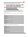
Verify “show vnetwork hosts” Shows All Hosts Discovered by vCenter
“show vnetwork hosts” will display ESX/ESXi host information. Verify all ESX/ESXi host’s uplinks
connected are shown.
switch# show vnetwork hosts
Host
Uplink Name
Uplink MAC
=========== ============== =================
ESX-4921
vmnic0
e4:1f:13:43:54:90
vmnic2
00:1b:21:8f:4a:f0
vmnic4
00:05:33:26:3e:ba
vmnic5
00:05:33:26:3e:bb
ESX-4922
vmnic0
e4:1f:13:43:95:5c
vmnic2
00:05:33:26:2d:90
vmnic3
00:05:33:26:2d:91
vmnic5
00:05:1e:eb:f9:94
(d)Virtual Switch
======================
vSwitch0
dvSwitch-Production
vSwitch3
dvSwitch-Production
vSwitch0
dvSwitch-Production
dvSwitch-Production
vSwitch3
Switch Interface
================
115/0/5
115/0/1
115/0/10
115/0/11
115/0/2
NOTE: In Fabric Cluster (FC) mode, only the locally connected interface information will be shown. For
example in the above output ESX-4921 - vmnic5 is not connected to this node (Rbridge-ID: 115)
3.2.2
Verify “show vnetwork vms” Shows All Virtual Machines in vCenter
“show vnetwork vms” will display the virtual machine information including host information and
associated MAC addresses of all VMs (vNIC MACs). These MAC are automatically associated to the
respective Port Profile. (Please refer to the “show vnetwork vmpolicy” command for more details).
switch# show vnetwork vms
Virtual Machine
Associated MAC
========================== =================
CentOS-4921
00:50:56:8e:00:4b
00:50:56:8e:00:4d
CentOS-4922
00:50:56:8e:00:50
00:50:56:8e:00:51
3.2.3
IP Addr
===========
-
Host
===========================
ESX-4921.englab.brocade.com
ESX-4921.englab.brocade.com
ESX-4922.englab.brocade.com
ESX-4922.englab.brocade.com
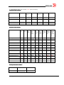
Verify “show vnetwork vmpolicy macaddr” Shows all VM/vmkernel MAC Addresses
“show vnetwork vmpolicy macaddr” lists all vNIC and vmkernel MAC addresses and shows the
respective Port Group and automatically created VCS Fabric Port Profile information.
switch# show vnetwork vmpolicy macaddr all
Associated MAC
Virtual Machine
================= ==========================
00:50:56:72:42:4c 00:50:56:78:69:36 00:50:56:7b:e5:41 00:50:56:7d:96:16 00:50:56:8e:00:4b CentOS-4921
00:50:56:8e:00:4d CentOS-4921
00:50:56:8e:00:50 CentOS-4922
00:50:56:8e:00:51 CentOS-4922
(dv)PortGroup
==================
ProductionVMs
VMkernel
ProductionVMs
VMkernel
ProductionVMs
TestVMs
TestVMs
ProductionVMs
Port-Profile
==================
auto-ProductionVMs
auto-VMkernel
auto-ProductionVMs
auto-VMkernel
auto-ProductionVMs
auto-TestVMs
auto-TestVMs
auto-ProductionVMs
NOTE: As shown in the “show vnetwork vmpolicy” output, NOS will automatically create Port Profiles
for vCenter Port Groups using the prefix “auto
autoauto-“. All vNIC and VMkernel MAC addresses are associated
with the automatically created VCS Fabric Port Profiles.
Strategic Solutions Lab
Page 28
3.2.4
show vnetwork vss
This command shows which vSwitch uplink is connected to which physical switch interface.
switch# show vnetwork vss
vSwitch
Host
================= ==============================
vSwitch0
ESX-4921.englab.brocade.com
ESX-4922.englab.brocade.com
vSwitch3
ESX-4921.englab.brocade.com
ESX-4922.englab.brocade.com
3.2.5
Uplink Name
==============
vmnic0
vmnic0
vmnic4
vmnic5
Switch Interface
================
115/0/1
115/0/2
show vnetwork pgs
“show vnetwork pgs” shows the standard virtual switch Port Group information.
switch# show
PortGroup
============
TestVMs
VMkernel
vnetwork pgs
vSwitch
===============
vSwitch1
vSwitch1
vSwitch1
vSwitch1
VlanID
=============
50-50,
50-50,
0-0,
0-0,
Host
============================
ESX-4922.englab.brocade.com
ESX-4921.englab.brocade.com
ESX-4922.englab.brocade.com
ESX-4921.englab.brocade.com
NOTE: “show vnetwork pgs” will quickly identify whether there is a VLAN misconfiguration. If the VLAN
IDs doesn’t match across the hosts for a given port-group, most probably it may be due to a user error.
3.2.6
show vnetwork dvs
“show vnetwork dvs” shows the distributed virtual switch information.
switch# show vnetwork
dvSwitch
=====================
dvSwitch-Production
3.2.7
dvs
Host
Uplink Name
============================== ==============
ESX-4921.englab.brocade.com
vmnic2
vmnic5
ESX-4922.englab.brocade.com
vmnic2
vmnic3
Switch Interface
================
115/0/5
115/0/10
115/0/11
show vnetwork dvpgs
“show vnetwork dvpgs” command shows the distributed virtual port group information.
switch# show vnetwork dvpgs
dvPortGroup
===================================
ProductionVMs
dvSwitch-Production-DVUplinks-7589
Strategic Solutions Lab
dvSwitch
===================================
dvSwitch-Production
dvSwitch-Production
Vlan
=========
10-10,
0-4094,
Page 29
4
Brocade VCS Fabric Layer 3 Features
There are a number of methods that an end-host can use to determine its first hop router to a
particular destination IP address. These include a dynamic routing protocol such as OSPF or a
statically configured default route. Running a dynamic routing protocol on every end-host may be
infeasible for a number of reasons. Neighbor or router discovery protocols may require active
participation by all hosts on a network. The use of a statically configured default route is quite popular;
it minimizes configuration and processing overhead on the end-host and is supported by virtually every
host’s IP implementation. The Virtual Router Redundancy Protocol (VRRP) is designed to eliminate the
single point of failure inherent in a static default routed environment.
The next sections review OSPF and VRRP-E configuration for a VCS Fabric of VDX switches. These
Layer 3 routing protocols were first introduced with NOS release 3.0.
4.1
OSPF
OSPF is a link-state routing protocol designed to be run within a single Autonomous System. Each
OSPF router maintains an identical database describing the Autonomous System's topology. From this
database, a routing table is calculated by constructing a shortest-path tree.
OSPF recalculates routes quickly in the face of topological changes, utilizing a minimum of routing
protocol traffic. OSPF provides support for equal-cost multipath. An area routing capability is provided,
enabling an additional level of routing protection and a reduction in routing protocol traffic. In addition,
all OSPF routing protocol exchanges are authenticated.
4.1.1
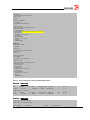
Topology used
The topology used for testing Layer 3 on Brocade VDX switches is as shown below:
Strategic Solutions Lab
Page 30
4.1.2
Validation of OSPF
Step 1 Configuring OSPF on VCS switches, initially begins by acquiring a ‘Layer 3 License’:
M8_159# show license
rbridge-id: 159
xxxxxxxxxxxxxxxxxxxxxxxxxxxxxxxxxxxxxxxx
Layer 3 license
Feature name:LAYER_3
xxxxxxxxxxxxxxxxxxxxxxxxxxxxxxxxxxxxxxxx
VCS Fabric license
Feature name:VCS_FABRIC
M8_159#
Step 2 Enable OSPF globally on the rbridge-id:
M8_159(config)# rbridge id 159
M8_159(config-rbridge-id-159)# router ospf
M8_159(conf-ospf-router)#
Step 3 Configure required area id under router OSPF command:
M8_159(config)# rbridge id 159
M8_159(config-rbridge-id-159)# router ospf
M8_159(conf-ospf-router)# area 10
M8_159(conf-ospf-router)#
Step 4 Configure interfaces under interfaces (ve or Layer 3) as required:
M8_159(config)# rbridge id 159
M8_159(config-rbridge-id-159)# interface ve 10
M8_159(config-Ve-10)# ip ospf area 10
M8_159(config-Ve-10)# ip ospf network broadcast
M8_159(config-Ve-10)# ip address 10.10.10.1/24
M8_159(config-Ve-10)# no shut
M8_159(config)# interface te 159/1/1
M8_159(conf-if-te-159/1/1)# interface ve 10
M8_159(conf-if-te-159/1/1)# ip ospf area 10
M8_159(conf-if-te-159/1/1)# ip ospf network broadcast
M8_159(conf-if-te-159/1/1)# ip address 10.10.10.1/24
M8_159(conf-if-te-159/1/1)# no shut
Step 5 Verify OSPF neighbors are up:
M8_159# show ip ospf neighbor
Port
Address Pri State
Neigh Address
Ve 10
10.1.1.1 1 FULL/DR 10.1.1.2
M8_159#
Neigh ID
10.1.1.1
Ev
5
Opt
2
Cnt
0
Step 6 Use other ‘show’ commands to verify OSPF configuration and route table:
Strategic Solutions Lab
Page 31
M4_157# show ip ospf interface ve 10
Ve 10 admin up, oper up
IP Address 10.1.1.1, Area 10
Database Filter: Not Configured
State DR-OTHER, Pri 1, Cost 1, Options 2,Type broadcast Events 195
Timers(sec): Transmit 1, Retrans 5, Hello 10, Dead 40
DR: Router ID 10.1.1.2
Interface Address 10.1.1.2
BDR: Router ID 10.1.1.1
Interface Address 10.1.1.1
Neighbor Count = 1, Adjacent Neighbor Count= 1
Neighbor:
10.1.1.2 [id 10.1.1.2] (DR)
Authentication-Key: None
MD5 Authentication: Key None, Key-Id None , Auth-change-wait-time 300
M4_157#
M4_157# show ip ospf config
Router OSPF: Enabled
Redistribution: Disabled
Default OSPF Metric: 10
OSPF Auto-cost Reference Bandwidth: Disabled
OSPF Redistribution Metric: Type2
OSPF External LSA Limit: 14913080
OSPF Database Overflow Interval: 0
RFC 1583 Compatibility: Enabled
Router id: 10.1.1.1
OSPF Area currently defined:
Area-ID
Area-Type Cost
0
normal
0
M4_157#
M8_159# show ip route
Total number of IP routes: 3
Type Codes - B:BGP D:Connected I:ISIS O:OSPF R:RIP S:Static; Cost - Dist/Metric
BGP Codes - i:iBGP e:eBGP
ISIS Codes - L1:Level-1 L2:Level-2
OSPF Codes - i:Inter Area 1:External Type 1 2:External Type 2 s:Sham Link
Destination
Gateway
Port
Cost
Type Uptime
1
10.1.1.0/24
DIRECT
Ve 10
0/0
D
5d9h
M8_159#
Step 7 If desired, configure static routes with different cost metric/distance values and verify that the
static route configuration is present in the routing table
M8_159# conf t
M8_159(config)# rbridge-id 159
M8_159(config-rbridge-id-159)# ip route 9.1.1.0/24 100.1.1.3 6
M8_159(config-rbridge-id-159)# exit
M8_159# show ip route static
Type Codes - B:BGP D:Connected I:ISIS O:OSPF R:RIP S:Static; Cost - Dist/Metric
BGP Codes - i:iBGP e:eBGP
ISIS Codes - L1:Level-1 L2:Level-2
OSPF Codes - i:Inter Area 1:External Type 1 2:External Type 2 s:Sham Link
Destination
Gateway
Port
Cost
Type Uptime
1
0.0.0.0/0
10.20.232.1
mgmt 1
1/1
S
2h8m
2
9.1.1.0/24
100.1.1.3
Ve 100
1/6
S
2h5m
M8_159#
M8_159# conf t
M8_159(config)# rbridge-id 159
M8_159(config-rbridge-id-159)# ip route 9.1.1.0/24 100.1.1.3 distance 15
M8_159(config-rbridge-id-159)# exit
M8_159# show ip route static
Type Codes - B:BGP D:Connected I:ISIS O:OSPF R:RIP S:Static; Cost - Dist/Metric
BGP Codes - i:iBGP e:eBGP
Strategic Solutions Lab
Page 32
ISIS Codes - L1:Level-1 L2:Level-2
OSPF Codes - i:Inter Area 1:External Type 1 2:External
Destination
Gateway
Port
1
0.0.0.0/0
10.20.232.1
mgmt 1
2
9.1.1.0/24
100.1.1.3
Ve 100
M8_159#
4.2
Type 2 s:Sham Link
Cost
Type Uptime
1/1
S
2h8m
15/1
S
2h5m
VRRP/VRRP-E
The Internet Engineering Task Force (IETF) has defined VRRP in RFC 2338.
VRRP (Virtual Router Redundancy Protocol) introduces the concept of a “virtual router,” which consists
of a virtual router identifier (VRID) and one or more IP addresses. Hosts use the virtual router’s IP
address(es) as their default gateway(s), just as they would with any router. The virtual router has a
virtual MAC address which is used for resolving ARP (address resolution protocol) requests.
VRRP protocols are designed to eliminate a single point of failure in a default route environment. VRRP
requires a “master router” and one or more “backup routers.” Routers running VRRP dynamically elect
master and backup routers. The VRRP master router controls the IP address(s) associated with a
virtual router. The Master forwards packets sent to these IP addresses. The election process provides
dynamic fail-over in the forwarding responsibility should the Master become unavailable. Any of the
virtual router's IP addresses on a LAN can then be used as the default first hop router by the endhosts. VRRP provides higher availability for the default path without requiring configuration of dynamic
routing or router discovery protocols on every end-host. Typical deployments use one backup router
The Brocade implementation of VRRP follows RFC 3768 and also provides the following additional
features:
• Track ports and track priority
• Hold time
• Capability of non-owner master to accept packets destined to virtual IP address
The VRRP standard protocol in RFC 3768 has a few limitations/drawbacks. A proprietary version of
VRRP that overcomes these limitations in VRRP-E (VRRP Extended) developed by Brocade for use in
Brocade IP enabled devices.
4.2.1
VRRP vs. VRRP-E
The following table summarizes the differences between VRRP and VRRP-E protocols VRRP
Virtual Router
Owner
Packets destined to
Virtual IP
VRRP router that has virtual router's
IP address(es) as real interface
address is the owner of virtual router
and has the highest priority.
Only virtual router owner responds to
the ICMP and IP packets destined to
the virtual IP address.
00-00-5e-00-01-{vrid} where
Virtual MAC
Strategic Solutions Lab
•
vrid is user configured 1
byte virtual router identifier.
Same VRID cannot be used
for two virtual router groups
VRRPVRRP-E
There are only master and backups.
There is no owner. All routers are
backup at startup, and the backup
with highest priority becomes the
master.
Any master can respond to the ICMP
and IP packets destined to the virtual
IP address.
02-e0-52-{hash-value}-{vrid}, where
•
‘hash-value’ is lower 2-byte
value of (BBCC*25(Hex) +
99AA) when virtual IP address
is say 0x99AABBCC
Page 33
in the same VLAN.
•
•
Source MAC in
VRRP Control
Packets
Gratuitous ARP
Source MAC in VRRP control packets
is virtual MAC address.
Gratuitous ARP request is sent only
once when the VRRP router becomes
master.
When track port goes down, the
current priority is reduced to the
track port priority.
Preemption is turned on by default.
Even if preemption is disabled, it
does not affect the owner router
Preemption
since owner preempts the active
master. Mastership switchover
causes unnecessary temporary
network disruption.
VRRP control packets have IP
VRRP IP Control
protocol type as 112 (reserved for
Packets
VRRP), and are sent to VRRP
multicast address 224.0.0.18.
Backup routers do not send any
Backup
advertisement messages. Only
advertisement
master sends the advertisement
message.
Table 1 VRRP and VRRPVRRP-E comparison table
Track Priority
02-e0-52 is Foundry's 24-bit
MAC OUI
vrid is user configured 1 byte
value. Same VRID can be
used for two or more virtual
router groups in the same
VLAN.
Source MAC in VRRP control packets
is physical MAC address.
Gratuitous ARP requests are sent
every 2 seconds by the virtual router
master. This is because VRRP control
packets do not use virtual MAC
address and thus virtual MAC address
entry in interconnecting switches
might get aged out.
When track port goes down, the
current priority is reduced by the track
port priority.
Preemption is turned off by default,
and there is no owner.
VRRP packets are UDP packets
destined to port 8888, and are sent to
all-router multicast address
224.0.0.2.
Backup routers as well send (backup)
advertisement messages which are
different from master advertisement
message.
Following are VRRP and VRRP-E configuration highlights on a Brocade VCS router:
a.
b.
c.
Both VRRP and VRRP-E protocol can be enabled at the same time on router.
Both VRRP and VRRP-E sessions can be configured on an interface at the same time.
VRRP and VRRP-E sessions cannot share the same VRID in a broadcast domain.
4.2.2
VRRP-E Parameters and Configuration
4.2.2.1 Short-path-forwarding Feature
In standard VRRP, packets destined to IP subnets which are local to the standby router cannot be
routed by the standby. These packets destined to the standby router with DA=VMAC would be
switched to the master and the master might route the packet back to the standby for routing.
Brocade uses short-path-forwarding to enhance this behavior in a VRRP-E configuration. The standby
router will try to route frames with DA=VMAC. Additionally, the VRRP virtual IP subnet is not configured
Strategic Solutions Lab
Page 34
as a local subnet on the standby, instead, a routing entry for the virtual IP subnet is installed pointing
toward the master.
For test short-path-forwarding or VRRP-E Active-Active configurations, please refer to test case 2 in
section 4.2.4.2.
Short-path-forwarding specific configurations:
M8_159(config)# rbridge-id 159
M8_159(config-rbridge-id-159)# protocol vrrp
M8_159(config-rbridge-id-159)# int ve 10
M8_159(config-Ve-10)# vrrp-extended-group 128
M8_159(config-vrrp-extended-group-128)# short-path-forwarding
M8_159(config-vrrp-extended-group-128)# exit
4.2.2.2 Track Port and Priority Command
Ports other than the VRRP instance interface can be tracked for up/down events. When port tracking
is enabled in a VRRP instance, the tracked port's link status is monitored. When a link down event is
detected on a tracked-port, the track priority is subtracted from the current router’s priority value.
Similarly, when link up event is detected on the tracked port, the track priority is added to the router’s
current priority value.
This dynamic change of router priority can trigger mastership switchover if the preemption is enabled.
The maximum number of interfaces that can be tracked for a virtual router is 16.
Track port and priority specific configurations:
M8_159(config)# rbridge-id 159
M8_159(config-rbridge-id-159)# protocol vrrp
M8_159(config-rbridge-id-159)# int ve 10
M8_159(config-Ve-10)# vrrp-extended-group 128
M8_159(config-vrrp-extended-group-128)# track port tengigabitethernet 1/1/48 priority 20
M8_159(config-vrrp-extended-group-128)# track port fortygigabitethernet 1/5/48 priority 20
M8_159(config-vrrp-extended-group-128)# track port port-channel 10 priority 20
M8_159(config-vrrp-extended-group-128)# exit
4.2.2.3 Hold Time Command
Hold time is the maximum number of seconds that elapse before a high-priority backup router
preempts the master router. Hold time is configured to allow all the software components to converge
on the backup router before preemption is triggered. A default value means switchover to higher
priority backup can immediately occur after the backup router comes online.
Hold-time ranges from 60-3600 seconds. The default hold-time is 60 seconds. When a hold-time
greater than the default value is provided, the backup router comes online after it waits for the hold
time interval and does not participate in the election protocol. So, even if a backup router has come
online that has a higher priority than the current master, the backup does not try to become master
until the hold-time period has expired.
Hold-time specific configurations:
Strategic Solutions Lab
Page 35
M8_159(config)# rbridge-id 159
M8_159(config-rbridge-id-159)# protocol vrrp
M8_159(config-rbridge-id-159)# int ve 10
M8_159(config-Ve-10)# vrrp-extended-group 128
M8_159(config-vrrp-extended-group-128)# hold-time
M8_159(config-vrrp-extended-group-128)# no advertise backup
M8_159(config-vrrp-extended-group-128)# exit
4.2.2.4 Advertise Backup Command
Backup routers send VRRP-E advertisement messages similar to the VRRP-E master, except that the
type field in the VRRP packet signifies that the message is a VRRP-E backup advertisement message.
When the master receives a backup advertisement, it updates the list of backup routers. Similarly,
when a VRRP-E backup receives a backup advertisement message, it updates the list of the other
backup routers in the group.
Advertise-backup specific configurations:
M8_159(config)# rbridge-id 159
M8_159(config-rbridge-id-159)# protocol vrrp
M8_159(config-rbridge-id-159)# int ve 10
M8_159(config-Ve-10)# vrrp-extended-group 128
M8_159(config-vrrp-extended-group-128)# advertise-backup
M8_159(config-vrrp-extended-group-128)# exit
4.2.2.5 Advertisement Interval Command
Advertisement-interval is the interval after which VRRP-E advertisement messages are resent by the
Master. This advertisement interval is in seconds and can be in the range of 1-255 seconds.
Advertisement-interval specific configurations:
M8_159(config)# rbridge-id 159
M8_159(config-rbridge-id-159)# protocol vrrp
M8_159(config-rbridge-id-159)# int ve 10
M8_159(config-Ve-10)# vrrp-extended-group 128
M8_159(config-vrrp-extended-group-128)# advertisement-interval 5
M8_159(config-vrrp-extended-group-128)# exit
4.2.2.6 Backup Advertisement Interval Command
Backup advertisement interval is the interval after which the Backup resends VRRP-E advertisement
messages to the Master. This backup advertisement interval is un seconds and can be in the range of
60-3600 seconds.
Backup-advertisement-interval specific configurations:
M8_159(config)# rbridge-id 159
M8_159(config-rbridge-id-159)# protocol vrrp
M8_159(config-rbridge-id-159)# int ve 10
M8_159(config-Ve-10)# vrrp-extended-group 128
M8_159(config-vrrp-extended-group-128)# backup-advertisement-interval 180
M8_159(config-vrrp-extended-group-128)# exit
4.2.2.7 Description Command
Any virtual router’s VRRP-E session is identified by its unique description field in the running-config.
Strategic Solutions Lab
Page 36
Description specific configurations:
M8_159(config)# rbridge-id 159
M8_159(config-rbridge-id-159)# protocol vrrp
M8_159(config-rbridge-id-159)# int ve 10
M8_159(config-Ve-10)# vrrp-extended-group 128
M8_159(config-vrrp-extended-group-128)# description VRRP_VCS_1
M8_159(config-vrrp-extended-group-128)# exit
4.2.2.8 Enable Command
Determines the administrative state of the virtual router, which can be either one of the following –
• disabled – The virtual router is configured on the interface but VRRP or VRRP-E has not been
activated on the interface.
• enabled – VRRP or VRRP-E has been activated on the interface.
VRRP/VRRP-E enable specific configurations:
M8_159(config)# rbridge-id 159
M8_159(config-rbridge-id-159)#
M8_159(config-rbridge-id-159)#
M8_159(config-rbridge-id-159)#
M8_159(config-rbridge-id-159)#
protocol vrrp
enable
no enable
exit
4.2.2.9 Preempt Mode Command
By default, a Backup that has a higher priority than another Backup that has become the Master can
preempt the Master, and take over the role of Master. The user has to disable preemption to prevent
this behavior.
Preemption applies only to Backup routers and takes effect only when the Master has failed and a
Backup has assumed ownership of the virtual router. This feature prevents a Backup with a higher
priority from taking over as Master from another Backup that has a lower priority but has already
become the Master of the virtual router.
Preemption is especially useful for preventing link-flaps in situations where there are multiple Backups
and a Backup with a lower priority than another Backup has assumed ownership, since Backup with
the higher priority was unavailable when ownership changed.
If the non-preempt mode (thus disabling the preemption feature) is enabled on all the Backups, the
Backup that becomes the Master following the disappearance of the Master continues to be Master.
The new Master is not preempted.
Preempt-mode specific configurations:
M8_159(config)# rbridge-id 159
M8_159(config-rbridge-id-159)# protocol vrrp
M8_159(config-rbridge-id-159)# int ve 10
M8_159(config-Ve-10)# vrrp-extended-group 128
M8_159(config-vrrp-extended-group-128)# preempt-mode
M8_159(config-vrrp-extended-group-128)# exit
Strategic Solutions Lab
Page 37
4.2.2.10 Priority Command
During negotiation, the router with the highest priority becomes the Master. If two or more devices are
tied with the highest priority, the Backup interface with the highest IP address becomes the Master for
the virtual router.
Priority specific configurations:
M8_159(config)# rbridge-id 159
M8_159(config-rbridge-id-159)# protocol vrrp
M8_159(config-rbridge-id-159)# int ve 10
M8_159(config-Ve-10)# vrrp-extended-group 128
M8_159(config-vrrp-extended-group-128)# priority 254
M8_159(config-vrrp-extended-group-128)# exit
4.2.2.11 Virtual IP Command
A virtual router’s VRRP-E session is identified by its unique virtual-ip address. Any Master can respond
to ICMP echo requests and IP packets for virtual IP address in VRRP-E context.
virtual-ip specific configurations:
M8_159(config)# rbridge-id 159
M8_159(config-rbridge-id-159)# protocol vrrp
M8_159(config-rbridge-id-159)# int ve 10
M8_159(config-Ve-10)# vrrp-extended-group 128
M8_159(config-vrrp-extended-group-128)# virtual-ip 10.1.1.157
M8_159(config-vrrp-extended-group-128)# enable
4.2.3
VRRP-E Verification and Statistics
4.2.3.1 Verify VRRP License
VRRP/VRRP-E are included with the ‘Layer 3 license’ and do not require a license of their own
M8_159# show license
rbridge-id: 159
xxxxxxxxxxxxxxxxxxxxxxxxxxxxxxxxxxxxxxxx
Layer 3 license
Feature name:LAYER_3
xxxxxxxxxxxxxxxxxxxxxxxxxxxxxxxxxxxxxxxx
VCS Fabric license
Feature name:VCS_FABRIC
M8_159#
4.2.3.2 Verify Master Election Occurs
Verify that the election process occurred and one of the switches is elected as Master, while the other
is Backup.
Strategic Solutions Lab
Page 38
M8_159# show vrrp interface ve 10
Total number of VRRP session(s)
: 1
VRID 128
Interface: Ve 10; Ifindex: 1207959560
Mode: VRRP-E
Admin Status: Enabled
Description :
Address family: IPv4
Authentication type: No Authentication
State: Master
Session Master IP Address: Local
Virtual IP(s): 10.1.1.157
Configured Priority: 100 (default: 100); Current Priority: 100
Advertisement interval: 1 sec (default: 1 sec)
Preempt mode: DISABLE (default: DISABLED)
Advertise-backup: DISABLE (default: DISABLED)
Backup Advertisement interval: 60 sec (default: 60 sec)
Short-path-forwarding: Disabled
Hold time: 0 sec (default: 0 sec)
Trackport:
Port(s)
Priority Port Status
=======
======== ===========
Statistics:
Advertisements: Rx: 2, Tx: 5
ARP:
Rx: 0, Tx: 2
M8_159#
M4_157# show vrrp interface ve 10
Total number of VRRP session(s)
: 1
VRID 128
Interface: Ve 10; Ifindex: 1207959560
Mode: VRRP-E
Admin Status: Enabled
Description :
Address family: IPv4
Authentication type: No Authentication
State: Backup
Session Master IP Address: 10.1.1.2
Virtual IP(s): 10.1.1.157
Configured Priority: 100 (default: 100); Current Priority: 100
Advertisement interval: 1 sec (default: 1 sec)
Preempt mode: DISABLE (default: DISABLED)
Advertise-backup: DISABLE (default: DISABLED)
Backup Advertisement interval: 60 sec (default: 60 sec)
Short-path-forwarding: Disabled
Hold time: 0 sec (default: 0 sec)
Trackport:
Port(s)
Priority Port Status
=======
======== ===========
Statistics:
Advertisements: Rx: 5, Tx: 2
ARP:
Rx: 0, Tx: 2
M4_157#
4.2.3.3 Verify the Virtual Router MAC is Present in the ARP Table.
Additionally verify that the other VRRP-E parameters such as virtual IP, short path forwarding,
advertisement interval, etc. are set.
Strategic Solutions Lab
Page 39
M8_159# show vrrp detail
Total number of VRRP session(s)
: 1
VRID 128
Interface: Ve 10; Ifindex: 1207959560
Mode: VRRP-E
Admin Status: Enabled
Description :
Address family: IPv4
Authentication type: No Authentication
State: Master
Session Master IP Address: Local
Backup Router(s):
Virtual IP(s): 10.1.1.157
Virtual MAC Address: 02e0.5200.0080
Configured Priority: 100 (default: 100); Current Priority: 100
Advertisement interval: 1 sec (default: 1 sec)
Preempt mode: DISABLE (default: DISABLED)
Advertise-backup: DISABLE (default: DISABLED)
Backup Advertisement interval: 60 sec (default: 60 sec)
Short-path-forwarding: Disabled
Hold time: 0 sec (default: 0 sec)
Master Down interval: 4 sec
Trackport:
Port(s)
Priority Port Status
=======
======== ===========
Global Statistics:
==================
Checksum Error : 0
Version Error : 0
VRID Invalid
: 0
Session Statistics:
===================
Advertisements
: Rx: 1346, Tx: 140
ARP
: Rx: 0, Tx: 71
Session becoming master
: 1
Advts with wrong interval : 0
Prio Zero pkts
: Rx: 0, Tx: 0
Invalid Pkts Rvcd
: 0
Bad Virtual-IP Pkts
: 0
Invalid Authenticaton type : 0
Invalid TTL Value
: 0
Invalid Packet Length
: 0
VRRP-E backup advt recvd
: 0
M8_159#
M8_159# show mac-address-table
VlanId
Mac-address
Type
8
0005.1ecd.050b
Dynamic
8
0005.336f.6e14
Dynamic
10
02e0.5200.0080
System
Total MAC addresses
: 3
M8_159#
Strategic Solutions Lab
State
Active
Active
Active
Ports
Po 8
Po 8
XX 159/X/X
Page 40
4.2.3.4
Clear VRRP-E Statistics.
M8_159# clear vrrp statistics ?
Possible completions:
interface
Interface information
session
Session
|
Output modifiers
<cr>
M8_159# clear vrrp statistics interface ?
Possible completions:
fortygigabitethernet
FortyGigabit Ethernet interface
gigabitethernet
Gigabit Ethernet interface
port-channel
Port-channel interface
tengigabitethernet
TenGigabit Ethernet interface
ve
Ve interface
M8_159# clear vrrp statistics interface ve 10 ?
Possible completions:
| <cr>
M8_159# clear vrrp statistics interface ve 10
M8_159#
4.2.4
Test Scenarios
4.2.4.1 Test Case 1: Configure VRRP Over vLAG in a VCS Fabric
This test verifies that VRRP traffic is forwarded appropriately. VRRP within a VCS Fabric should be
configured on VE interfaces, which enable VRRP advertisement frames to be send over the VCS Fabric.
A typical example of VRRP deployment is shown below.
Layer 3 Cloud
Master
interface ve 100
ip addr 20.0.0.1/24
R1
vrrp-group 100
virtual-ip 20.0.0.100
Standby
R2
interface ve 100
ip addr 20.0.0.2/24
vrrp-group 100
virtual-ip 20.0.0.100
VCS Cloud
R3
R4
H1
H2
Typical VRRP deployment in VCS cluster
In the above, R1 and R2 form a VRRP group with R1 as Master and R2 as Backup. VRRP
advertisement frames are broadcast by R1 on VLAN 100. Since the VCS Fabric ports on all of the VDX
switches forward all VLAN traffic, R1 and R2 are able to see each other’s advertisement frames.
Strategic Solutions Lab
Page 41
Virtual MAC address (VMAC) is distributed to all the VCS nodes within the cluster. When a VCS node
becomes VRRP master, it triggers VMAC distribution across the cluster, which is then added to each
individual node’s MAC table as an entry pointing towards the master node.
To begin, initially configure VRRP (use commands described in section 3.2.3.1) for the above
mentioned topology.
a.
b.
c.
d.
Configure VRRP-group 100 under interface ve 10 with virtual-ip address 20.0.0.100 on both
R1 and R2.
Enable the group 100 on both R1 and R2.
Verify that the VMAC is learnt on R1 which is the Master.
Verify traffic forwarding works as expected using various “show” commands.
4.2.4.2 Test Case 2: Configure “Active/Active” VRRP-E Over vLAG in a VCS Fabric
In addition to the above mentioned VRRP configuration, VRRP-E short-path-forwarding feature is also
available in VCS mode on VE interfaces as mentioned in Sec Error! Reference
Reference source not found..
found. A
backup router participates in VRRP-E session only when short-path-forwarding is configured and hence
has its effect only on the backup router, though all VCS nodes are aware of VRRP-E session and
participating nodes in each session. Once short-path-forwarding is configured, a backup router routes
the frames destined to the VMAC instead of switching them to the master.
Layer 3 Cloud
Master
interface ve 10
ip address 162.85.1.2/24 R1
vrrp-entended-group 1
virtual-ip 162.85.1.5
short-path-forwarding
Standby
R2
interface ve 10
ip address 162.85.1.1/24
vrrp-entended-group 1
virtual-ip 162.85.1.5
short-path-forwarding
VCS Cloud
IP: 162.85.1.100
G/w IP: 162.85.1.5
R3
R4
H1
H2
IP: 162.85.1.101
G/w IP: 162.85.1.5
ActiveActive-Active VRRPVRRP-E loadload-balancing in VCS
The VRRP-E active-active load-balancing scenario is shown in the figure above, where VRRP-E with
short-path-forwarding (SPF) is configured on R1 & R2. Other switches, R3 & R4, do not participate in
VRRP-E, but are aware of the VRRP-E sessions and members in VCS.
Switches R1-R2 exchanges advertisement frames over VLAN 10 and elect a master, say R1. Since SPF
is enabled on R2, when a frame is received which has to be routed by the VRRP-E master, R2 routes
the frame locally.
Switches R3 & R4, have the Virtual MAC Layer 2 entry pointed to a virtual node, which is uniquely
allocated for each VRRP-E session in the VCS Fabric. A virtual node is a grouping of physical nodes in
Strategic Solutions Lab
Page 42
the VCS Fabric. Each frame which enters into the VCS Fabric via R3-R4 hits this entry and the packet is
load-balanced among the virtual node group members, viz R1 & R2. The packet load-balancing is
performed in the fast-path using hardware-based hashing.
To begin, initially configure VRRP-E (use commands described in section 3.2.3.1) for the above
mentioned topology –
a. Configure VRRP-extended-group 1 under interface ve 10 with virtual-ip address 162.85.1.5 on
both R1 and R2.
b. Enable the group 1 on both R1 and R2.
c. Verify that the VMAC is learned on both R1 and R2.
d. Verify that traffic forwarding works as expected using various “show” commands.
Strategic Solutions Lab
Page 43
5
Brocade VCS Fabric Integration with
Classic Ethernet Architectures
5.1
Integration with Classic Layer 2 Ethernet
5.1.1
Create a vLAG Between VCS Fabric and Nexus 7000 Core
All members of a Brocade VCS Fabric behave as a single logical Layer 2 Ethernet switch. As such, it is
possible to create a link aggregation group (LAG) that spans multiple VCS Fabric members. This is
known as a virtual LAG (vLAG). Externally facing ports support all classic Ethernet protocols to
interoperate with any standards-compliant Layer 2 Ethernet switch. In the following example, we will
configure a vLAG between a Brocade VCS Fabric and a pair of Nexus 7000 switches configured with
virtual port channels (vPC).
First, create a port channel interface with four members spanning two VDX switches (two members per
switch):
RB1#
RB1#
RB1#
RB1#
RB1#
RB1#
RB1#
RB1#
RB1#
RB1#
conf t
int te 1/0/6
channel-group 20 mode active type standard
lacp timeout long
no shutdown
int te 1/0/7
channel-group 20 mode active type standard
lacp timeout long
no shutdown
exit
RB2#
RB2#
RB2#
RB2#
RB2#
RB2#
RB2#
RB2#
RB2#
RB2#
conf t
int te 2/0/6
channel-group 20 mode active type standard
lacp timeout long
no shutdown
int te 2/0/7
channel-group 20 mode active type standard
lacp timeout long
no shutdown
exit
Then configure the port channel interface as a trunk interface for VLAN 1:
RB1#
RB1#
RB1#
RB1#
RB1#
RB1#
RB1#
RB1#
conf t
int po 20
description vlag_to_n7k
switchport
switchport mode trunk
switchport trunk allowed vlan 1
no shutdown
exit
RB1#
RB1#
RB1#
RB1#
RB1#
RB1#
RB1#
RB1#
conf t
int po 20
description vlag_to_n7k
switchport
switchport mode trunk
switchport trunk allowed vlan 1
no shutdown
exit
Strategic Solutions Lab
Page 44
Next, set up the port channel on the appropriate interfaces of the Nexus 7000 vPC pair, and connect
the cables between the Nexus 7000 vPC pair and the VCS Fabric. Verify that the port channel
interfaces are up on both RBridges:
RB1# show po 20
RB2# show po 20
Start traffic between a server attached to the Nexus 7000 vPC pair and another one connected to the
VCS Fabric and verify the traffic is load balanced across all the vLAG members based on the hashing
algorithm.
5.1.2
Create a vLAG Between VCS Fabric and a Server
The same way a Layer 2 Ethernet switch can establish a LAG terminating on multiple VCS Fabric
members, a server can configure an active/active NIC team that terminates on two VCS Fabric
members.
First, assign two interfaces on different VDX switches to the new port channel:
RB2#
RB2#
RB2#
RB2#
RB2#
RB2#
conf t
int te 2/0/9
channel-group 40 mode active type standard
lacp timeout long
no shutdown
exit
RB3#
RB3#
RB3#
RB3#
RB3#
RB3#
conf t
int te 3/0/5
channel-group 40 mode active type standard
lacp timeout long
no shutdown
exit
Define the port channel as an access interface for VLAN 1:
RB2#
RB2#
RB2#
RB2#
RB2#
RB2#
RB2#
RB2#
conf t
int po 40
description vlag_to_SRV3
switchport
switchport mode access
switchport access vlan 1
no shutdown
exit
RB3#
RB3#
RB3#
RB3#
RB3#
RB3#
RB3#
RB3#
conf t
int po 40
description vlag_to_SRV3
switchport
switchport mode access
switchport access vlan 1
no shutdown
exit
Using the server adapter management tools, configure an active/active NIC team and connect the
server to the port channel member interfaces. Verify the port channel is up on both RBridges:
RB2# show po 40
Strategic Solutions Lab
Page 45
RB3# show po 40
Establish traffic between SRV3 and another server in the VCS Fabric and verify that traffic is loadbalanced between the two vLAG members based on the hashing algorithm.
5.2
Integration with Classic Layer 3 IP
The purpose of this test is to demonstrate Layer 2/Layer 3 interoperability of OSPF within a VCS Fabric
using NOS 3.x.
5.2.1
Test Topology
The following diagram shows the topology for testing OSPF in a VCS Fabric. OSPF support was
introduced with NOS release 3.0.0.
5.2.2
Build Two-Node VCS Fabric with OSFP
5.2.2.1 Setting Up OSPF, VRRP and VE between two VDXs
Note: OSPF is configured under the RBridge-ID.
VDX6720-75
interface vlan 100
shutdown
Strategic Solutions Lab
Page 46
!
rbridge-id 1
ip route 0.0.0.0/0 10.18.233.1
router ospf
area 0
!
interface Loopback 1
no shutdown
ip address 10.10.10.20/32
!
protocol vrrp
chassis virtual-ip 10.18.233.75/24
interface Ve 100
ip ospf area 0
ip mtu 1500 VDX inserted this and the next line
ip proxy-arp
ip address 1.1.1.210/24
no shutdown
vrrp-group 100
virtual-ip 1.1.1.230
enable
preempt-mode
VDX6710-27
interface vlan 100
shutdown
!
rbridge-id 2
ip route 0.0.0.0/0 10.18.233.1
router ospf
area 0
!
interface Loopback 1
no shutdown
ip address 10.10.10.10/32
!
protocol vrrp
chassis virtual-ip 10.18.233.27/24
interface Ve 100
ip ospf area 0
ip mtu 1500
ip proxy-arp
ip address 1.1.1.200/24
no shutdown
vrrp-group 100
virtual-ip 1.1.1.230
enable
preempt-mode
5.2.2.2
5.2.2.2.1
Verify VCS Fabric is Running OSFP, VRRP and VE
OSFP Check
VDX6720-75# sh ip ospf nei
Port
Address
Pri State
Ve 100
1.1.1.210
1
FULL/BDR
Neigh Address
Neigh ID
1.1.1.200
10.10.10.10
Ev
5
Opt Cnt
2
0
VDX6710-27# sh ip ospf nei
Port
Address
Pri State
Ve 100
1.1.1.200
1
FULL/DR
Neigh Address
Neigh ID
1.1.1.210
10.10.10.20
Ev
6
Opt Cnt
2
0
5.2.2.2.2
VRRP Check
VDX6720-75# show vrrp summary
Total number of VRRP session(s)
VRID
Session
Interface
Strategic Solutions Lab
: 1
State
Description
Page 47
====
100
=======
VRRP
=========
Ve 100
=====
Master
===========
State
=====
Backup
Description
===========
VDX6710-27# show vrrp summary
Total number of VRRP session(s)
VRID
====
100
Session
=======
VRRP
5.2.2.2.3
: 1
Interface
=========
Ve 100
VE Check
VDX6720-75# ping 1.1.1.200
Type Control-c to abort
PING 1.1.1.200 (1.1.1.200): 56 data bytes
64 bytes from 1.1.1.200: icmp_seq=0 ttl=64 time=2.746 ms
64 bytes from 1.1.1.200: icmp_seq=1 ttl=64 time=3.246 ms
64 bytes from 1.1.1.200: icmp_seq=2 ttl=64 time=3.639 ms
64 bytes from 1.1.1.200: icmp_seq=3 ttl=64 time=3.271 ms
64 bytes from 1.1.1.200: icmp_seq=4 ttl=64 time=2.573 ms
--- 1.1.1.200 ping statistics --5 packets transmitted, 5 packets received, 0% packet loss
round-trip min/avg/max/stddev = 2.573/3.095/3.639/0.386 ms
5.2.2.3 Create a vLAG Between VCS Fabric and the PC on Nexux 7K
Configure a vLAG on the selected VDX switches:
VDX6720-75
interface TenGigabitEthernet 1/0/1
fabric isl enable
fabric trunk enable
channel-group 100 mode active type standard
lacp timeout long This is automatically inserted by NOS
!
interface TenGigabitEthernet 1/0/2
fabric isl enable
fabric trunk enable
channel-group 100 mode active type standard
lacp timeout long
no shutdown
interface Port-channel 100
vlag ignore-split VDX inserted this automatically
switchport
switchport mode access
switchport access vlan 1
no shutdown
VDX6710-27
interface TenGigabitEthernet 2/0/50
fabric isl enable
fabric trunk enable
channel-group 100 mode active type standard
lacp timeout long
no shutdown
!
interface TenGigabitEthernet 2/0/51
fabric isl enable
fabric trunk enable
channel-group 100 mode active type standard
lacp timeout long
no shutdown
interface Port-channel 100
vlag ignore-split VDX inserted this automatically
switchport
Strategic Solutions Lab
Page 48
switchport mode access
switchport access vlan 1
no shutdown
Next we’ll configure all four ports on the Nexus 7000 that will be part of our port-channel that will be
connected to the VCS Fabric.
Nexus7K-4(config)# feature lacp
Nexus7K-4(config)# interface port-channel 200
Nexus7K-4(config-if)# no shutdown
Nexus7K-4(config)# int ethernet 8/29 - 32
Nexus7K-4(config-if-range)# channel-group 200 mode active
5.2.2.4 VCS vLAG and Cisco NX-OS Port-Channel Verification
Verify the vLAG is configured in the VCS Fabric:
VDX6720-75# show port-channel summary
LACP Aggregator: Po 100 (vLAG) you want to see this!
Aggregator type: Standard
Ignore-split is disabled
Member rbridges:
rbridge-id: 1 (2)
rbridge-id: 2 (2)
Admin Key: 0100 - Oper Key 0100
Member ports on rbridge-id 1:
Link: Te 1/0/1 (0x118008000) sync: 1
*
Link: Te 1/0/2 (0x118010001) sync: 1
VDX6710-27# show port-channel summary
LACP Aggregator: Po 100 (vLAG) you want to see this!
Aggregator type: Standard
Ignore-split is disabled
Member rbridges:
rbridge-id: 1 (2)
rbridge-id: 2 (2)
Admin Key: 0100 - Oper Key 0100
Member ports on rbridge-id 2:
Link: Te 2/0/50 (0x21819000F) sync: 1
Link: Te 2/0/51 (0x218198010) sync: 1
Verify the vLAG connection on the Nexus 7000:
Note:
Note Next to po200 we see (SU), from the flags this is telling you that this PC is switched and up
which is what we want. Also next to each of the ports in our PC, we see each port with the letter “P”
next to it which indicates that the port is up and a member in our PC.
Strategic Solutions Lab
Page 49
5.2.3
Create OSFP Neighbors Between Nexus 7000 and VCS
5.2.3.1
Configure Two Ports on Each VDX with OSPF area 0
VDX6710-27
VDX6710-27(config)# interface TenGigabitEthernet 2/0/52
VDX6710-27(conf-if-te-2/0/52)# shut
VDX6710-27(conf-if-te-2/0/52)# no switchport
VDX6710-27(conf-if-te-2/0/52)# ip address 20.20.20.1/24
VDX6710-27(conf-if-te-2/0/52)# ip ospf area 0
VDX6710-27(conf-if-te-2/0/52)#
VDX6710-27(conf-if-te-2/0/53)#
VDX6710-27(conf-if-te-2/0/53)#
VDX6710-27(conf-if-te-2/0/53)#
VDX6710-27(conf-if-te-2/0/53)#
int ten 2/0/53
shut
no switchport
ip address 30.30.30.1/24
ip ospf area 0
VDX6720-75
VDX6720-75(config)# int ten 1/0/3
VDX6720-75(conf-if-te-1/0/3)# shut
VDX6720-75(conf-if-te-1/0/3)# no switchport
VDX6720-75(conf-if-te-1/0/3)# ip address 40.40.40.1/24
VDX6720-75(conf-if-te-1/0/3)# ip ospf area 0
VDX6720-75(conf-if-te-1/0/3)#
VDX6720-75(conf-if-te-1/0/4)#
VDX6720-75(conf-if-te-1/0/4)#
VDX6720-75(conf-if-te-1/0/4)#
VDX6720-75(conf-if-te-1/0/4)#
int ten 1/0/4
shut
no switchport
ip address 50.50.50.1/24
ip ospf area 0
Note:
Note Some of the NOS messages to the console were removed for clarity.
5.2.3.2
Configure Two Ports on Each Nexus 7000 with OSFP area 0
N7K-1
Nexus7K(config)# router ospf 1
Nexus7K(config-router)# router-id 1.1.1.1
Nexus7K(config) eth 1/10
Nexus7K(config-if)#shut
Nexus7K(config-if)# no switchport
Nexus7K(config-if)# ip address 30.30.30.2 255.255.255.0
Nexus7K(config-if)# ip router ospf 1 area 0
Nexus7K(config)# router ospf 1
Nexus7K(config-router)# int eth 1/2
Nexus7K(config-if)# ip address 50.50.50.2 255.255.255.0
Nexus7K(config-if)# ip router ospf 1 area 0
Nexus7K(config-if)# no shut
N7K-2
Nexus7K-Nexus7K-2(config)# router ospf 1
Nexus7K-Nexus7K-2(config-router)# router-id 1.1.1.2
Nexus7K-Nexus7K-2(config-router)# int eth 1/27
Nexus7K-Nexus7K-2(config-if)# shut
Nexus7K-Nexus7K-2(config-if)# no switchport
Nexus7K-Nexus7K-2(config-if)# ip address 20.20.20.2 255.255.255.0
Nexus7K-Nexus7K-2(config-if)# ip router ospf 1 area 0
Nexus7K-Nexus7K-2(config-if)# no shut
Nexus7K-Nexus7K-2(config)# router ospf 1
Nexus7K-Nexus7K-2(config-router)# int eth 1/18
Nexus7K-Nexus7K-2(config-if)# no switchport
Nexus7K-Nexus7K-2(config-if)# ip address 40.40.40.2 255.255.255.0
Nexus7K-Nexus7K-2(config-if)# ip router ospf 1 area 0
Nexus7K-Nexus7K-2(config-if)# no shut
Strategic Solutions Lab
Page 50
5.2.3.3
OSPF Verification
Nexus 7K-VCS OSPF
Nexus7K-Nexus7K-2# sh ip ospf nei
OSPF Process ID 1 VRF default
Total number of neighbors: 2
Neighbor ID
Pri State
10.10.10.20
1 FULL/DR
10.10.10.10
1 FULL/DR
Up Time Address
00:00:13 40.40.40.1
00:43:03 20.20.20.1
Interface
Eth1/18
Eth1/27
Nexus7K# sh ip ospf nei
OSPF Process ID 1 VRF default
Total number of neighbors: 2
Neighbor ID
Pri State
10.10.10.20
1 FULL/DR
10.10.10.10
1 FULL/DR
Up Time Address
00:00:12 50.50.50.1
00:47:42 30.30.30.1
Interface
Eth1/2
Eth1/10
VCS-Nexus 7K OSPF
VDX6710-27# sh ip ospf nei
Port
Address
Pri
Ve 100
1.1.1.200
1
Gi 2/0/1
2.2.2.10
128
Te 2/0/53
30.30.30.1
1
Te 2/0/52
20.20.20.1
1
NOTE: Gi 2/0/1 is an OSFP neighbor
adjacent VDX in our VCS Fabric.
VDX6720-75# sh ip ospf nei
Port
Address
Ve 100
1.1.1.210
Te 1/0/3
40.40.40.1
Te 1/0/4
50.50.50.1
Pri
1
1
1
State
FULL/DR
FULL/DR
FULL/BDR
FULL/BDR
to a Juniper based
Neigh Address
Neigh ID
Ev
Opt
1.1.1.210
10.10.10.20
4
2
2.2.2.20
2.2.2.20
5
2
30.30.30.2
1.1.1.1
5
2
20.20.20.2
1.1.1.2
2
2
OSFP cloud. VE100 is our OSFP neighbor with
Cnt
0
0
0
0
our
State
FULL/BDR
FULL/BDR
FULL/BDR
Neigh Address
1.1.1.200
40.40.40.2
50.50.50.2
Cnt
0
0
0
Neigh ID
10.10.10.10
1.1.1.2
1.1.1.1
Ev
6
5
5
Opt
2
2
2
5.2.3.4 Nexus 7000 OSPF Route Checking
Note:
show ip route”
Note On each Nexus 7000 verify some number of “intra area” routes exist via the “show
route
command done on each of the two Nexus 7000s.
N7K-2
Nexus7K-Nexus7K-2# sh ip route
IP Route Table for VRF "default"
'*' denotes best ucast next-hop
'**' denotes best mcast next-hop
'[x/y]' denotes [preference/metric]
'%<string>' in via output denotes VRF <string>
1.1.1.0/24, ubest/mbest: 1/0, attached
*via 1.1.1.2, Lo0, [0/0], 3d22h, direct
1.1.1.2/32, ubest/mbest: 1/0, attached
*via 1.1.1.2, Lo0, [0/0], 3d22h, local
2.2.2.0/24, ubest/mbest: 1/0
*via 20.20.20.1, Eth1/27, [110/5], 3d22h, ospf-1, intra
10.10.10.0/24, ubest/mbest: 1/0, attached
*via 10.10.10.1, Po1, [0/0], 4d19h, direct
10.10.10.1/32, ubest/mbest: 1/0, attached
*via 10.10.10.1, Po1, [0/0], 4d19h, local
20.20.20.0/24, ubest/mbest: 1/0, attached
*via 20.20.20.2, Eth1/27, [0/0], 3d22h, direct
20.20.20.2/32, ubest/mbest: 1/0, attached
*via 20.20.20.2, Eth1/27, [0/0], 3d22h, local
30.30.30.0/24, ubest/mbest: 1/0
*via 20.20.20.1, Eth1/27, [110/5], 3d22h, ospf-1, intra
40.40.40.0/24, ubest/mbest: 1/0, attached
*via 40.40.40.2, Eth1/18, [0/0], 01:42:06, direct
40.40.40.2/32, ubest/mbest: 1/0, attached
*via 40.40.40.2, Eth1/18, [0/0], 01:42:06, local
50.50.50.0/24, ubest/mbest: 1/0
*via 40.40.40.1, Eth1/18, [110/5], 01:41:19, ospf-1, intra
Strategic Solutions Lab
Page 51
N7K-1
Nexus7K# sh ip route
IP Route Table for VRF "default"
'*' denotes best ucast next-hop
'**' denotes best mcast next-hop
'[x/y]' denotes [preference/metric]
'%<string>' in via output denotes VRF <string>
1.1.1.0/24, ubest/mbest: 1/0, attached
*via 1.1.1.1, Lo0, [0/0], 3d22h, direct
1.1.1.1/32, ubest/mbest: 1/0, attached
*via 1.1.1.1, Lo0, [0/0], 3d22h, local
2.2.2.0/24, ubest/mbest: 1/0
*via 30.30.30.1, Eth1/10, [110/5], 3d22h, ospf-1, intra
10.10.10.0/24, ubest/mbest: 1/0, attached
*via 10.10.10.2, Po1, [0/0], 4d19h, direct
10.10.10.2/32, ubest/mbest: 1/0, attached
*via 10.10.10.2, Po1, [0/0], 4d19h, local
20.20.20.0/24, ubest/mbest: 1/0
*via 30.30.30.1, Eth1/10, [110/5], 3d22h, ospf-1, intra
30.30.30.0/24, ubest/mbest: 1/0, attached
*via 30.30.30.2, Eth1/10, [0/0], 3d22h, direct
30.30.30.2/32, ubest/mbest: 1/0, attached
*via 30.30.30.2, Eth1/10, [0/0], 3d22h, local
40.40.40.0/24, ubest/mbest: 1/0
*via 50.50.50.1, Eth1/2, [110/5], 01:41:10, ospf-1, intra
50.50.50.0/24, ubest/mbest: 1/0, attached
*via 50.50.50.2, Eth1/2, [0/0], 01:41:57, direct
50.50.50.2/32, ubest/mbest: 1/0, attached
*via 50.50.50.2, Eth1/2, [0/0], 01:41:57, local
5.2.3.5
VCS OSFP Route Checking
VDX6710-27# show ip route
Total number of IP routes: 9
Type Codes - B:BGP D:Connected I:ISIS O:OSPF R:RIP S:Static; Cost - Dist/Metric
BGP Codes - i:iBGP e:eBGP
ISIS Codes - L1:Level-1 L2:Level-2
OSPF Codes - i:Inter Area 1:External Type 1 2:External Type 2 s:Sham Link
Destination
Gateway
Port
Cost
Type Uptime
1
0.0.0.0/0
10.18.233.1
mgmt 1
1/1
S
14d0h
2
1.1.1.0/24
DIRECT
Ve 100
0/0
D
1h47m
3
2.2.2.0/24
DIRECT
Gi 2/0/1
0/0
D
14d0h
4
10.10.10.10/32
DIRECT
Lo 1
0/0
D
14d0h
5
10.18.233.0/24
DIRECT
mgmt 1
0/0
D
14d0h
6
20.20.20.0/24
DIRECT
Te 2/0/52
0/0
D
3d22h
7
30.30.30.0/24
DIRECT
Te 2/0/53
0/0
D
3d22h
8
40.40.40.0/24
1.1.1.210
Ve 100
110/2
O
1h46m OSPF
9
50.50.50.0/24
1.1.1.210
Ve 100
110/2
O
1h46m OSPF
VDX6720-75# show ip route
Total number of IP routes: 10
Type Codes - B:BGP D:Connected I:ISIS O:OSPF R:RIP S:Static; Cost - Dist/Metric
BGP Codes - i:iBGP e:eBGP
ISIS Codes - L1:Level-1 L2:Level-2
OSPF Codes - i:Inter Area 1:External Type 1 2:External Type 2 s:Sham Link
Destination
Gateway
Port
Cost
Type Uptime
1
0.0.0.0/0
10.18.233.1
mgmt 1
1/1
S
1h49m
2
1.1.1.0/24
DIRECT
Ve 100
0/0
D
1h49m
3
1.1.1.230/32
DIRECT
Ve 100
0/0
D
1h49m
4
2.2.2.0/24
1.1.1.200
Ve 100
110/2
O
1h48m <- OSPF
5
10.10.10.20/32
DIRECT
Lo 1
0/0
D
1h49m
6
10.18.233.0/24
DIRECT
mgmt 1
0/0
D
1h49m
7
20.20.20.0/24
1.1.1.200
Ve 100
110/2
O
1h48m <- OSPF
8
30.30.30.0/24
1.1.1.200
Ve 100
110/2
O
1h48m <- OSPF
9
40.40.40.0/24
DIRECT
Te 1/0/3
0/0
D
1h49m
10
50.50.50.0/24
DIRECT
Te 1/0/4
0/0
D
1h49m
Strategic Solutions Lab
Page 52
5.2.3.6 Nexus 7000 with VRF up to VCS Fabric with OSPF
Next, configure VRF or Layer-3 Virtualization (NX-OS speak) on the 30 network to provide some
isolation as is commonly done for a data center/service provider environment.
Create VRF on a Nexus 7000:
Nexus7K(config)# vrf context vrf-finance
Enable VRF under the OSFP process:
Nexus7K(config)# router ospf 1
vrf vrf-finance
Enable VRF on the 30 network interface that is running OSPF in the VCS Fabric:
Nexus7K(config-if)# vrf member vrf-finance
% Deleted all L3 config on interface Ethernet1/10
Right now YOUR OSPF Neighbor is DOWN!
<---DONT FORGET TO ADD THE IP and OSPF INFO BACK IN.
VRF OSFP verification:
Nexus7K(config-router-vrf)# sh ip ospf nei
OSPF Process ID 1 VRF default
Total number of neighbors: 1
Neighbor ID
Pri State
Up Time Address
10.10.10.20
1
FULL/DR
20:10:46 50.50.50.1
Interface
Eth1/2
Notice the 30 network is no longer visible in the default VRF, as expected. The default VRF, like the
default VDC, cannot be deleted on a Nexus 7000.
Nexus7K(config-router-vrf)# sh ip ospf nei vrf vrf-finance
OSPF Process ID 1 VRF vrf-finance
Total number of neighbors: 1
Neighbor ID
Pri State
Up Time Address
10.10.10.10
1
FULL/DR
00:06:04 30.30.30.1
Interface
Eth1/10
Show the VDX switch in the OSPF VCS Fabric with the VRF OSPF neighbor.
VDX6710-27# sh ip ospf nei
Port
Ve 100
Gi 2/0/1
Te 2/0/52
Te 2/0/53
Address
1.1.1.200
2.2.2.10
20.20.20.1
30.30.30.1
Pri
1
128
1
1
State
FULL/BDR
FULL/DR
FULL/DR
FULL/BDR
Neigh Address
1.1.1.210
2.2.2.20
20.20.20.2
30.30.30.2
Neigh ID
10.10.10.20
2.2.2.20
1.1.1.2
30.30.30.2
Ev
4
6
5
4
Opt
2
2
2
2
Cnt
0
0
1
0
The 30 network is up and running.
Verify the VRF configuration on the Nexus 7000:
Strategic Solutions Lab
Page 53
Nexus7K# sh vrf vrf-finance
VRF-Name
vrf-finance
Strategic Solutions Lab
VRF-ID State
3
Reason
Up
--
Page 54
Strategic Solutions Lab
Page 55
6
Multi-hop FCoE
Leveraging Brocade VCS Fabric technology, Brocade VDX Data Center Switches provide the foundation
for Ethernet fabrics—revolutionizing the design of Layer 2 networks and enabling cloud-optimized
networking.
One of the key differentiators of Brocade VCS Fabric technology is the support for multi-hop FCoE
functionality. Users can connect FCoE initiators and FCoE targets anywhere in the VCS Fabric and run
FCoE traffic.
6.1
Install FCoE License:
The FCoE BASE license is required on VDX 6720/6730 switches that have FCoE servers/targets
directly attached.
1. View existing licenses on switch
RB201_68_fc24# show license
2. Add the FCoE license
RB201_68_fc24# license add licStr “<FCOE_BASE LICENSE STRING>”
For license to take effect, it may be necessary to disable/enable ports or switch...
3. Disable/enable switch
RB201_68_fc24# chassis disable
Are you sure you want to disable all chassis ports now? [y/n]: y
Strategic Solutions Lab
Page 56
RB201_68_fc24#
RB201_68_fc24# Chassis enable
4. Verify the FCoE license is added correctly
RB201_68_fc24# show license
rbridge-id: 201
xxxxxxxxxxxxxxxxxxxxxxxxxxxxxxxxxxxxxxxx
FCoE Base license
Feature name:FCOE_BASE
xxxxxxxxxxxxxxxxxxxxxxxxxxxxxxxxxxxxxxxx
6.2
Enabling FCoE port on interface TenGigabitEthernet
1. Configure FCoE on the TenGigabitEthernet interface
RB201_68_fc24# configure terminal
Entering configuration mode terminal
RB201_68_fc24(config)# interface TenGigabitEthernet 201/0/19
RB201_68_fc24(conf-if-te-201/0/19)# fcoeport default
RB201_68_fc24(conf-if-te-201/0/19)# no shutdown
2. Verify the FCoE configuration
RB201_68_fc24# show running-config interface tengigabitethernet 201/0/19
interface TenGigabitEthernet 201/0/19
fabric isl enable
fabric trunk enable
fcoeport default
no shutdown
!
3. Verify the FCoE device login and note the device WWN and the corresponding FCoE
Port interface
RB201_68_fc24# show fcoe login
=============================================================================================
FCOE-Port
Te-port
Device WWN
Device MAC
Session MAC
=============================================================================================
Fcoe 1/201/19
Te 201/0/19
10:00:00:05:33:48:71:8a 00:05:33:48:71:8a 0e:fc:00:c9:2b:00
Total number of Logins = 1
NOTE: Repeat step 2 for each and every port where FCoE CNA / FCoE targets are connected.
6.3
Creating LUNs
Create the appropriate LUN and LUN masks on the FCoE/FC target. Please refer to the appropriate
storage array user manual for a detailed description of the configuration procedure.
6.4
Discovering LUNs
After creating the appropriate LUN masks, the server can discover the LUNs through the servers CNA.
The following shows how to verify LUNs in a Windows environment.
Strategic Solutions Lab
Page 57
Right Click on My Computer -> Manage -> Server Manager -> Storage -> Disk Management -> Rescan
Disks
Note: In Linux: “fdisk –l” should show the visible luns
6.5
Starting FCoE traffic through a Windows Host
After discovering the LUNs, start the FCoE traffic. The following show sample screenshots from the
“Medusa Labs Test Tools” application in a Windows environment.
Strategic Solutions Lab
Page 58
Strategic Solutions Lab
Page 59
7
FCoE-to-FC Bridging
The Brocade VDX 6730 Switches have Ethernet and Fibre Channel ports and can provide an
interconnect for the FCoE servers attached to a VCS based FCoE fabric with storage devices and
services attached to FOS Fibre Channel fabrics. The VDX6730-32 has 24 Ethernet ports and 8 Fibre
Channel ports, and VDX 6730-76 has 60 Ethernet ports and 16 Fibre Channel ports. With the release
of the Brocade Network Operating System (NOS) v2.1.1, Brocade protects existing investments by
bridging Fibre Channel SAN and Ethernet fabrics. Organizations can utilize FCoE capabilities on
various Brocade VDX switches and connect to Fibre Channel SAN fabrics (running FOS v7.0.1 or later)
using Brocade VDX 6730 and Brocade Fibre Channel Router (FCR).
In the following section “NOS” refers to a Brocade VCS Fabric running the Brocade Network Operating
System and “FOS” refers to a Brocade Fiber Channel fabric running the Brocade Fabric Operating
System.
NOTE: FCoE to Fibre Channel interconnect is supported with Brocade NOS v2.1.1 or higher connected
to Brocade FOS v7.0.1 or higher.
7.1
Supported Topologies
Below are the set of topologies supported for interconnecting edge fabrics using Brocade Fibre
Channel routers.
7.1.1
VCS Fabrics as Fibre Channel Edge Fabrics with Fibre Channel Backbone Fabric
Figure 1 - NOS VCS Fabric edge to FOS backbone sharing
Each pink NOS Fabric is treated as a Fiber Channel Edge Fabric and each one is an independent VCS
Fabric with FCoE traffic. The blue Backbone Fabric is a Fiber Channel Backbone Fabric with Fiber
Channel routing and Fiber Channel devices.
Strategic Solutions Lab
Page 60
7.1.2
Edge-to-Edge Sharing Using a Single Fibre Channel Backbone Fabric
Edge-to-edge sharing is supported for NOS-to-NOS, NOS-to-FOS and FOS-to-FOS scenarios. In this case
Fiber Channel routing is within the Backbone Fabric, but Fiber Channel Devices are connected to
independent Fiber Channel Edge Fabrics. VCS Fabrics connect FCoE initiator and target devices.
Figure 2 – Edge to edge sharing using a single backbone
7.1.3
Edge-to-Edge Sharing Ssing Dual Backbone
Figure 3 – Edge to edge sharing using dual backbone
The configuration provides high-availability with dual Fibre Channel Backbone Fabrics. Should a
Backbone Fabric fail, traffic will automatically reroute through the remaining Backbone Fabric.
Strategic Solutions Lab
Page 61
7.2
Configuring FCoE-FC Interconnect
NOTE: Before connecting new VDX6730 switches into an existing VCS Fabric, make sure all the
switches in the existing VCS Fabric are upgraded to NOS v2.1.1 or higher and the new VDX6730
switches are also running NOS v2.1.1 or higher.
7.2.1
Installing FCoE BASE License on VDX 6720/6730
The FCoE BASE license is required on VDX 6720/6730 switches that have FCoE servers/targets
directly attached. For details on VDX switch licenses such as VCS, Dynamic Ports on Demand (DPOD)
etc., refer the Network OS Administrator’s Guide for the NOS release.
Adding FCoE License
1. View existing licenses on the switch
RB201_68_fc24# show license
2. Add the FCoE license
RB201_68_fc24# license add licStr “<FCOE_BASE LICENSE STRING>”
For license to take effect, it may be necessary to disable/enable ports or switch...
3. Disable/enable the switch
RB201_68_fc24# chassis disable
Are you sure you want to disable all chassis ports now? [y/n]: y
RB201_68_fc24#
RB201_68_fc24# chassis enable
4. Verify the FCoE license is added correctly
RB201_68_fc24# show license
rbridge-id: 201
xxxxxxxxxxxxxxxxxxxxxxxxxxxxxxxxxxxxxxxx
FCoE Base license
Feature name:FCOE_BASE
Xxxxxxxxxxxxxxxxxxxxxxxxxxxxxxxxxxxxxxxx
7.2.2
Viewing and Configuring FCoE ports on VDX 6720/6730
FCoE enabled servers should be directly connected to VDX 6720/6730 switches via CNAs supporting
FC-BB-5 compliant FCoE services.
Viewing and Configuring FCoE Parameters
1. View the default/existing FCoE parameters
RB201_68_fc24# show fcoe fabric-map
============================================================================
Fabric-Map
VLAN
VFID
Pri
FCMAP
FKA
Timeout
============================================================================
default
1002[D] 128[D]
3[D] 0xefc00[D] 8000[D] Enabled[D]
Total number of Fabric Maps = 1
RB201_68_fc24# show running-config fcoe
fcoe
fabric-map default
vlan 1002
Strategic Solutions Lab
Page 62
priority 3
virtual-fabric 128
fcmap 0E:FC:00
advertisement interval 8000
keep-alive timeout
!
map default
fabric-map default
cee-map default
!
!
2. [Optional] To modify the default/existing FCoE parameters, enter the “config-fcoefabric-map” command in the running-config: {Default configuration is recommended}
RB201_68_fc24# configure terminal
Entering configuration mode terminal
RB201_68_fc24(config)# fcoe
RB201_68_fc24(config-fcoe)# fabric-map default
RB201_68_fc24(config-fcoe-fabric-map)# ?
Possible completions:
advertisement
Configure the FIP Advertisement interval
do
Run an operational-mode command
exit
Exit from current mode
fcmap
Configure the FCMAP value for a FCoE Fabric-map
help
Provide help information
keep-alive
Enable/Disable the keep-alive timeout
no
Negate a command or set its defaults
priority
Configure the priority for the FCoE Fabric-map
pwd
Display current mode path
top
Exit to top level and optionally run command
virtual-fabric
Configure the Virtual-Fabric ID for the FCoE Fabric-map
vlan
Configure the VLAN for the FCoE Fabric-map
Enabling FCoE Port on Interface TenGigabitEthernet
4. Configure FCoE on the TenGigabitEthernet interface
RB201_68_fc24# configure terminal
Entering configuration mode terminal
RB201_68_fc24(config)# interface TenGigabitEthernet 201/0/19
RB201_68_fc24(conf-if-te-201/0/19)# fcoeport default
RB201_68_fc24(conf-if-te-201/0/19)# no shutdown
5. Verify the FCoE configuration
RB201_68_fc24# show running-config interface tengigabitethernet 201/0/19
interface TenGigabitEthernet 201/0/19
fabric isl enable
fabric trunk enable
fcoeport default
no shutdown
!
6. Verify the FCoE device login and note the device WWN and corresponding FCoE Port
interface
RB201_68_fc24# show fcoe login
=============================================================================================
FCOE-Port
Te-port
Device WWN
Device MAC
Session MAC
=============================================================================================
Strategic Solutions Lab
Page 63
Fcoe 1/201/19
Te 201/0/19
10:00:00:05:33:48:71:8a
00:05:33:48:71:8a
0e:fc:00:c9:2b:00
Total number of Logins = 1
RB201_68_fc24# show fcoe interface brief
===========================================================================
FCOE IF
Mode
Status
Binding
Num
Config Current Config
Proto
VN Ports
===========================================================================
1/201/1
VF
VF
Up
Down
Te 201/0/1
0
1/201/2
VF
VF
Up
Down
Te 201/0/2
0
1/201/3
VF
VF
Up
Down
Te 201/0/3
0
.
. <truncated>
.
1/201/17
VF
VF
Up
Down
Te 201/0/17
0
1/201/18
VF
VF
Up
Down
Te 201/0/18
0
1/201/19
VF
VF
Up
Up
Te 201/0/19
1
1/201/20
VF
VF
Up
Down
Te 201/0/20
0
. <truncated>
Total number of Interfaces : 24
7. View the FCoE interface statistics
RB201_68_fc24# show interface fcoe 1/201/19
Interface Fcoe 1/201/19
--------------------------------------------------------Fcoe 1/201/19 is Up, Line protocol is Up
Ethernet port is TenGigabitEthernet 201/0/19
Interface index (ifindex) is 403898386
Config Mode is VF, Current Mode is VF
Last clearing of show interface counters: 2011-11-17 21:12:50.846992
RX Statistics:
Num of FIP VLAN Discovery Requests : 1
Num of FIP Discovery Solicitations : 1
Num of FIP FLOGIs
: 1
Num of FIP NPIV FDISCs
: 0
Num of FIP LOGOs
: 0
Num of FIP Enode Keep Alives
: 1399
Num of FIP VN Port Keep Alives
: 124
Errors
: 0
TX Statistics:
Num of FIP VLAN Discovery Responses : 1
Num of FIP Discovery SA
: 1
Num of FIP Discovery UA
: 1427
Num of FLOGI/FDISC ACCs
: 1
Num of LS_RJT (FLOGI, FDISC, LOGO) : 0
Num of CVLs
: 0
Time since last status change : 2011-11-17 21:13:33.483007
Total number of Interfaces : 1
7.2.3
Viewing and Configuring FC Ports on a VDX 6730
The Fibre Channel ports on the VDX 6730 must be connected to a Brocade Fibre Channel router for
FCoE to Fibre Channel interconnectivity. The Fibre Channel ports on VDX 6730 are pre-provisioned to
connect to a Brocade Fibre Channel router.
Viewing and Configuring VDX 6730 Fibre Channel ports
1. View default Fibre Channel ports state and Fibre Channel interface configuration
RB201_68_fc24# show fabric islports
Strategic Solutions Lab
Page 64
Name:
RB201_68_fc24
Type:
96.2
State:
Online
Role:
Fabric Subordinate
VCS Id:
8192
Config Mode:Local-Only
Rbridge-id: 201
WWN:
10:00:00:05:33:6f:3c:6a
FCF MAC:
00:05:33:6f:3c:6a
Index
Interface
State
Operational State
===================================================================
1
Te 201/0/1
Down
2
Te 201/0/2
Down
.
. <Truncated>
.
22
Te 201/0/22
Down
23
Te 201/0/23
Down
24
Te 201/0/24
Down
49
Fi 201/0/1
Down
50
Fi 201/0/2
Down
51
Fi 201/0/3
Down
52
Fi 201/0/4
Down
53
Fi 201/0/5
Down
54
Fi 201/0/6
Down
55
Fi 201/0/7
Down
56
Fi 201/0/8
Down
RB201_68_fc24# show running-config interface FibreChannel 201/0/1
interface FibreChannel 201/0/1
desire-distance 0
no isl-r_rdy
trunk-enable
no shutdown
!
2. [Optional] To modify default/existing Fibre Channel configuration, navigate to the
FibreChannel interface in the running-config: {Default configuration is recommended
and FibreChannel interfaces are pre-provisioned to connect to Brocade FCR}
RB201_68_fc24# configure terminal
Entering configuration mode terminal
RB201_68_fc24(config)# interface FibreChannel 201/0/1
RB201_68_fc24(config-FibreChannel-201/0/1)# ?
Possible completions:
desire-distance
Configure Desired distance for LS and LD mode.
do
Run an operational-mode command
exit
Exit from current mode
fill-word
Configure Fill Word
help
Provide help information
isl-r_rdy
Enable ISL-R_rdy Mode
long-distance
Configure Long Distance
no
Negate a command or set its defaults
pwd
Display current mode path
shutdown
Shutdown the selected interface
speed
Configure Speed
top
Exit to top level and optionally run command
trunk-enable
Enable Trunk
vc-link-init
Enable VC Link Init
3. View the FC interface statistics
RB201_68_fc24# show interface Fibrechannel 201/0/1
fibrechannel 201/0/1 is up (In_Sync). Protocol state is up (connected).
Pluggable media present
Strategic Solutions Lab
Page 65
LineSpeed Actual:
PortSpeed:
portDisableReason:
PortId:
PortIfId:
PortWwn:
Distance:
8G Auto
N8Gbps
None
c93100
43020021
20:31:00:05:33:6f:3c:6a
normal
Last clearing of show interface counters: 00:35:53
Interrupts:
0
Link_failure: 0
Unknown:
0
Loss_of_sync: 0
Lli:
0
Loss_of_sig: 0
Proc_rqrd:
0
Protocol_err: 0
Timed_out:
0
Invalid_word: 0
Rx_flushed:
0
Invalid_crc: 0
Tx_unavail:
0
Delim_err:
0
Free_buffer:
0
Address_err: 0
Overrun:
0
Lr_in:
0
Suspended:
0
Lr_out:
0
Parity_err:
0
Ols_in:
0
2_parity_err:
0
Ols_out:
0
Frjt:
Fbsy:
0
0
Rate info:
Bandwidth:
8.00G
Tx performance: 0 B/sec
Rx performance: 85.7MB/sec
7.2.4
Defining and Enabling LSAN Zoning Configuration in a VCS Fabric
For devices to be shared between a VCS Fabric and a SAN Fabric via Fibre Channel routing, Logical
SAN (LSAN) Zoning should be used. An LSAN Zone is similar to a traditional Fibre Channel zone and is
created using the zoning tools but uses a special naming prefix “LSAN_”. LSAN Zones define which
devices can send traffic to each other when they are located in independent fabrics, either VCS
Fabrics or SAN Fabrics.
NOTE: Please refer Network OS Administrator’s Guide (v2.1.0 or higher) for details on zoning
configuration and administration.
LSAN zoning must be enabled in all fabrics that share devices to other fabrics
•
•
Edge-to-edge routing: edge fabrics
Backbone-to-edge routing: backbone and edge fabrics
1. View the default/existing zoning configuration on any VDX switch in the VCS Fabric
RB201_68_fc24# show running-config zoning
zoning enabled-configuration cfg-name ""
zoning enabled-configuration default-zone-access allaccess
zoning enabled-configuration cfg-action cfg-save
2. Have the list of WWNs of the devices to be shared between fabrics.
3. Define the LSAN zone and add the WWNs of the devices to be connected between
fabrics.
RB201_68_fc24# configure terminal
Entering configuration mode terminal
RB201_68_fc24(config)# zoning defined-configuration zone LSAN_host_target_1
Strategic Solutions Lab
Page 66
RB201_68_fc24(config-zone-LSAN_host_target_1)# member-entry 10:00:00:05:33:48:71:8a FCoE Host
RB201_68_fc24(config-zone-LSAN_host_target_1)# member-entry 15:7e:00:11:0d:00:00:02 FC Target
4. Define a cfg and add the defined LSAN Zone to the cfg
RB201_68_fc24(config)# zoning defined-configuration cfg cfg_vcs8192
RB201_68_fc24(config-cfg-cfg_vcs8192)# member-zone LSAN_host_target_1
5. Verify the zoning defined-configuration and enabled-configuration
RB201_68_fc24(config)# do show running-config zoning defined-configuration
zoning defined-configuration cfg cfg_vcs8192
member-zone LSAN_host_target_1
!
zoning defined-configuration zone LSAN_host_target_1
member-entry 10:00:00:05:33:48:71:8a
member-entry 15:7e:00:11:0d:00:00:02
!
RB201_68_fc24(config)# do show running-config zoning enabled-configuration
zoning enabled-configuration cfg-name ""
zoning enabled-configuration default-zone-access allaccess
zoning enabled-configuration cfg-action cfg-none
6. Enable the zoning defined cfg
RB201_68_fc24(config)# zoning enabled-configuration cfg-name cfg_vcs8192
RB201_68_fc24(config)#
7. Verify the zoning enabled-configuration again to check the cfg is now enabled
RB201_68_fc24(config)# show running-config zoning enabled-configuration
zoning enabled-configuration cfg-name cfg_vcs8192
zoning enabled-configuration default-zone-access allaccess
zoning enabled-configuration cfg-action cfg-save
zoning enabled-configuration enabled-zone LSAN_host_target_1
member-entry 10:00:00:05:33:48:71:8a
member-entry 15:7e:00:11:0d:00:00:02
!
7.2.5
Creating and Enabling LSAN Zoning Configuration in Fibre Channel SAN Fabric
Create and enable an identical LSAN Zone in the SAN Fabric where the Fibre Channel device (Target)
is attached.
NOTE: Use identical LSAN Zone names for ease of identification and administration; however this is
not a requirement. For complete details on FOS Zoning and LSAN Zone configuration, refer to the
Fabric OS Administrator’s Guide for the FOS release.
T_5300_114:FID128:root> zonecreate LSAN_host_target_1,"10:00:00:05:33:48:71:8a;15:7e:00:11:0d:00:00:02"
T_5300_114:FID128:root> cfgcreate cfg_fid10,"LSAN_host_target_1"
T_5300_114:FID128:root> cfgenable cfg_fid10
T_5300_114:FID128:root> cfgshow
<Truncated>
Effective configuration:
cfg:
cfg_fid10
zone: LSAN_host_target_1
10:00:00:05:33:48:71:8a
Strategic Solutions Lab
Page 67
15:7e:00:11:0d:00:00:02
7.2.6
Enabling Fibre Channel Routing (FCR) Service on FOS Switch
In order for the VCS Fabric to connect to Fibre Channel SAN, the VDX6730 Fibre Channel ports should
be connected to a FOS Switch running Fibre Channel Routing Service (FCR). To establish an Interfabric link, the Fibre Channel ports on the FCR connected to the VDX 6730 must be configured as EXports for Brocade NOS Fabric Mode, or mode 5.
NOTE: Fibre Channel routing is a licensed feature that requires the Integrated Routing (IR) license for
sharing between Fibre Channel devices in two Fibre Channel SAN fabrics. The IR license is NOT
required for sharing devices in a VCS Fabric and a Fibre Channel SAN fabric or between two VCS
Fabrics. Without an IR license, device sharing will be blocked between Fibre Channel devices in Fibre
Channel Edge Fabrics. For details on FCR licensing, supported platforms and configuration, refer to
the Fabric OS Administrator’s Guide for the FOS release.
It is recommended that Physical connections between the VCS Fabric and the FCR be done after the
FCR EX-ports are configured.
Viewing and Configuring FCR
1. Check whether the FC Routing service is enabled
FCR6510:root> fosconfig --show
FC Routing service:
iSCSI service:
iSNS client service:
Virtual Fabric:
Ethernet Switch Service:
disabled
Service not supported on this Platform
Service not supported on this Platform
disabled
Service not supported on this Platform
2. Enable the FC Routing service
FCR6510:root> fosconfig --enable fcr
2011/11/17-05:50:41, [FCR-1069], 306719, INFO, FCR6510, The FC Routing service is enabled.
FC Routing service is enabled
3. Verify the FC Routing service is enabled
FCR6510:root> fosconfig --show
FC Routing service:
iSCSI service:
iSNS client service:
Virtual Fabric:
Ethernet Switch Service:
7.2.7
enabled
Service not supported on this Platform
Service not supported on this Platform
disabled
Service not supported on this Platform
Configuring Inter-fabric link (IFL) on the Fibre Channel Router (FCR)
To create an Inter-fabric link (IFL) between the Fibre Channel ports on the VDX 6730 and the ports on
the Fibre Channel Router, the corresponding Fibre Channel ports on the FCR must be configured to
support Brocade NOS Fabric Mode, or Mode 5. The Fiber Channel ports on the FCR connected to the
Fibre Channel SAN Edge Fabric switches need not specify any mode. Mode 0 is the default mode
Configuring Fibre Channel Router EX-Ports in Mode 5 for VCS Fabrics Connectivity
Strategic Solutions Lab
Page 68
NOTE:
NOTE: If the FCR ports are connected to the VDX 6730 before configuring them as EX-ports (mode 5),
the VDX 6730 may show the port operational state in “show fabric islports” as below:
53
Fi 201/0/5
Down
Down (ESC NOS incompatible)
Configure the EX-ports on FCR as below and then perform a shut/no shut on the Fibre Channel
interface.
1. Disable the ports that are to be configured as EX-ports (the ones connected to VDX
6730).
In the example below, ports 28, 29, 30, 31 of the FCR6510 would be physically connected to
VDX 6730 ports 5, 6, 7, 8
FCR6510:root>
FCR6510:root>
FCR6510:root>
FCR6510:root>
portdisable
portdisable
portdisable
portdisable
28
29
30
31
2. Configure each port that connects to the VDX 6730 as an EX-port
• Set the Fabric ID for the VCS Fabric (avoid using fabric IDs 1 and 128, which
are the default IDs for backbone connections.) [120 in example below]
• (Optional) Set the unique Front Domain ID to identify the FCR on the edge
(VCS Fabric) [60 in example below]
• Set the operational mode to 5-Brocade NOS fabric
TIP: If the VDX 6730 switch is connected to more than one FCR, you can customize and manually
configure a Front Domain ID (FD) for each FCR while configuring the EX-ports on it. This helps to
easily identifying the FCR from all its Edge Fabrics. Make sure you use the same unique Front
Domain for a given FCR.
FCR6510:root> portcfgexport 28 -a 1 -f 120 -m 5 -d 60
2011/03/12-07:36:30, [FCR-1071], 616, FID 128, INFO, FCR6510, Port 28 is changed from non FCR port
to FCR port.
FCR6510:root> portcfgexport 29 -a 1 -f 120 -m 5 -d 60
FCR6510:root> portcfgexport 30 -a 1 -f 120 -m 5 -d 60
FCR6510:root> portcfgexport 31 -a 1 -f 120 -m 5 -d 60
3. Enable the ports
FCR6510:root>
FCR6510:root>
FCR6510:root>
FCR6510:root>
portenable
portenable
portenable
portenable
28
29
30
31
4. Verify EX-ports are correctly configured.
FCR6510:root> portcfgexport 28
Port
28
info
Admin:
enabled
State:
NOT OK
Pid format:
Not Applicable
Operate mode:
Brocade NOS
Edge Fabric ID:
120
Preferred Domain ID:
60
Front WWN:
50:00:53:31:37:a3:ee:78
Fabric Parameters:
Auto Negotiate
Strategic Solutions Lab
Page 69
R_A_TOV:
Not Applicable
E_D_TOV:
Not Applicable
Authentication Type: None
DH Group: N/A
Hash Algorithm: N/A
Edge fabric's primary wwn: N/A
Edge fabric's version stamp: N/A
This port can now be connected to the VCS Edge Fabric. Verify all EX-ports are correctly
configured.
5. Physically attach the Inter-Fabric Link (IFL) from the Fibre Channel Router to the VDX
6730 switch in the VCS Fabric.
NOTE: A Fibre Channel Router can interconnect multiple fabrics. EX-ports attached to more than
one Edge Fabric have a different Fabric ID for each Edge Fabric.
Configuring EX-Ports in Brocade Native Mode (Mode 0) for Fibre Channel SAN Edge Fabric
1. Disable the ports on the Fibre Channel router that will be configures as EX-ports
connecting to switches in the Fibre Channel SAN Edge Fabric. In the example below,
ports 16, 17, 18, 19 of the FCR6510 are connected to FC SAN Edge Fabric switch
T_5300 on its ports 76, 77, 78, 79
FCR6510:root>
FCR6510:root>
FCR6510:root>
FCR6510:root>
portdisable
portdisable
portdisable
portdisable
16
17
18
19
2. Configure each port on the Fibre Channel router that connects to the T_5300 as an
EX-port
• Set the Fabric ID for the FC SAN edge fabric (avoid using fabric IDs 1 and
128, which are the default IDs for backbone connections.) [10 in example
below]
• (Optional) Set the unique Front Domain ID to identify the FCR on the edge
(FC SAN fabric) [60 in example below; same as set on this FCR for VCS
Fabric]
• [optional; Default is mode 0] Set the operational mode to Brocade Native
mode 0
FCR6510:root> portcfgexport 16 -a 1 -f 10
2000/03/13-03:30:02, [FCR-1071], 620, FID
port to FCR port.
FCR6510:root> portcfgexport 17 -a 1 -f 10
FCR6510:root> portcfgexport 18 -a 1 -f 10
FCR6510:root> portcfgexport 19 -a 1 -f 10
-d 60
128, INFO, FCR6510, Port 16 is changed from non FCR
-d 60
-d 60
-d 60
3. Enable the ports on the Fibre Channel router
FCR6510:root>
FCR6510:root>
FCR6510:root>
FCR6510:root>
portenable
portenable
portenable
portenable
Strategic Solutions Lab
16
17
18
19
Page 70
4. Verify the EX-ports are correctly configured.
FCR6510:root> portcfgexport 16
Port
16
info
Admin:
enabled
State:
NOT OK
Pid format:
Not Applicable
Operate mode:
Brocade Native
Edge Fabric ID:
10
Preferred Domain ID:
60
Front WWN:
50:00:53:31:37:a3:ee:0a
Fabric Parameters:
Auto Negotiate
R_A_TOV:
Not Applicable
E_D_TOV:
Not Applicable
Authentication Type: None
DH Group: N/A
Hash Algorithm: N/A
Edge fabric's primary wwn: N/A
Edge fabric's version stamp: N/A
This port can now be connected to the Fibre Channel SAN Edge Fabric. Verify that all EX-ports
are correctly configured.
5. Physically attach the IFL from the Fibre Channel Router to the Fibre Channel SAN
Edge Fabric switch, switch T_5300.
7.2.8
Verifying Connectivity Between the Backbone and Edge Fabrics
Once the cables between the FCR and VDX 6730 switch in the VCS Fabric, and the FCR and Fibre
Channel SAN Edge Fabric switch are physically attached, verify connectivity.
Verify Connectivity From FCR
1. Verify the EX-port, Edge Fabric ID (VCS/FC), name of the edge VDX 6730 switch, and
name of the edge FC fabric switch are correct.
FCR6510:root> switchshow
<Truncated>
16 16
061300
id
N8
Online
(fabric id = 10 )(Trunk master)
17 17
061000
id
N8
Online
18 18
061200
id
N8
Online
19 19
061100
id
N8
Online
<Truncated>
28 28
061c00
id
N8
Online
(fabric id = 120 )(Trunk master)
29 29
061f00
id
N8
Online
30 30
061e00
id
N8
Online
31 31
061d00
id
N8
Online
FC
EX-Port
10:00:00:05:33:41:39:02 "T_5300_114"
FC
FC
FC
EX-Port
EX-Port
EX-Port
(Trunk port, master is Port 16 )
(Trunk port, master is Port 16 )
(Trunk port, master is Port 16 )
FC
EX-Port
10:00:00:05:33:6f:3c:6a "RB201_68_fc24"
FC
FC
FC
EX-Port
EX-Port
EX-Port
(Trunk port, master is Port 28 )
(Trunk port, master is Port 28 )
(Trunk port, master is Port 28 )
FCR6510:root> portcfgexport 28
Port
28
info
Admin:
enabled
State:
OK
Pid format:
Not Applicable
Operate mode:
Brocade NOS
Edge Fabric ID:
120
Front Domain ID:
60
Front WWN:
50:00:53:31:37:a3:ee:78
Principal Switch:
202
Principal WWN:
10:00:00:05:33:6f:3a:1a
Fabric Parameters:
Auto Negotiate
R_A_TOV:
10000(N)
Strategic Solutions Lab
Page 71
E_D_TOV:
2000(N)
Authentication Type: None
DH Group: N/A
Hash Algorithm: N/A
Edge fabric's primary wwn: N/A
Edge fabric's version stamp: N/A
FCR6510:root> portcfgshow
Area Number:
Octet Speed Combo:
Speed Level:
Fill Word(On Active)
Fill Word(Current)
AL_PA Offset 13:
Trunk Port
<Truncated>
EX Port
<Truncated>
28
28
1(16G|8G|4G|2G)
AUTO(SW)
0(Idle-Idle)
0(Idle-Idle)
OFF
ON
ON
FCR6510:root> portcfgexport 16
Port
16
info
Admin:
enabled
State:
OK
Pid format:
core(N)
Operate mode:
Brocade Native
Edge Fabric ID:
10
Front Domain ID:
60
Front WWN:
50:00:53:31:37:a3:ee:0a
Principal Switch:
30
Principal WWN:
10:00:00:05:1e:0f:28:16
Fabric Parameters:
Auto Negotiate
R_A_TOV:
10000(N)
E_D_TOV:
2000(N)
Authentication Type: None
DH Group: N/A
Hash Algorithm: N/A
Edge fabric's primary wwn: N/A
Edge fabric's version stamp: N/A
FCR6510:root> portcfgshow
Area Number:
Octet Speed Combo:
Speed Level:
Fill Word(On Active)
Fill Word(Current)
AL_PA Offset 13:
Trunk Port
<Truncated>
EX Port
<Truncated>
16
19
1(16G|8G|4G|2G)
AUTO(SW)
0(Idle-Idle)
0(Idle-Idle)
OFF
ON
ON
NOTE: For the FCR to VDX IFL, if the FCR “switchshow” output does not show the configured ports
as FC EX-Port or the “portcfgexport <port#>” shows “State: NOT OK”, or the VDX 6730 shows the
corresponding Fibre Channel port on “show fabric islports” output as:
53
Fi 201/0/5
Down
Down (ESC NOS incompatible)
Then, perform a shut/no shut on the Fibre Channel interface on VDX 6730 (as shown below) and
re-verify.
RB201_68_fc24# configure terminal
Strategic Solutions Lab
Page 72
Entering configuration mode terminal
RB201_68_fc24(config)# in fi 201/0/5
RB201_68_fc24(config-FibreChannel-201/0/5)# shut
RB201_68_fc24(config-FibreChannel-201/0/5)# no shut
2. View all edge fabric switch names and ensure links are working as expected.
FCR6510:root> fcrfabricshow
FC Router WWN: 10:00:00:05:33:13:7a:3e, Dom ID:
6,
Info: 10.20.52.197, "FCR6510"
EX_Port
FID
Neighbor Switch Info (enet IP, WWN, name)
-----------------------------------------------------------------------17
10
10.20.52.114
10:00:00:05:33:41:39:02
"T_5300_114"
21
20
10.20.52.116
10:00:00:05:1e:c3:1e:14
"T_7800_116"
<Truncated>
28
120
10.20.52.68
10:00:00:05:33:6f:3c:6a
"RB201_68_fc24"
Verify Connectivity From VCS Edge Fabric
1. Verify the corresponding Fibre Channel E-port on the VDX 6730, the Front Domain ID of the FCR,
and the Translate Domain of the SAN Edge Fabric where the Fibre Channel device (Target) is
attached. This device WWN is the one added to the LSAN Zone.
RB201_68_fc24# show fabric islports
Name:
RB201_68_fc24
Type:
96.2
State:
Online
Role:
Fabric Subordinate
VCS Id:
8192
Config Mode:Local-Only
Rbridge-id: 201
WWN:
10:00:00:05:33:6f:3c:6a
FCF MAC:
00:05:33:6f:3c:6a
Index
Interface
State
Operational State
===================================================================
1
Te 201/0/1
Down
2
Te 201/0/2
Down
<Truncated>
53
Fi 201/0/5
Up
ISL 50:00:53:31:37:a3:ee:78 "fcr_fd_60" (Trunk Primary)
54
Fi 201/0/6
Up
ISL (Trunk port, Primary is Fi 201/0/5 )
55
Fi 201/0/7
Up
ISL (Trunk port, Primary is Fi 201/0/5 )
56
Fi 201/0/8
Up
ISL (Trunk port, Primary is Fi 201/0/5 )
RB201_68_fc24# show fab isl
Rbridge-id: 201
#ISLs: 8
Src
Src
Nbr
Nbr
Index
Interface
Index
Interface
Nbr-WWN
BW
Trunk Nbr-Name
---------------------------------------------------------------------------------------------7
Te 201/0/7
9
Te 202/0/9
10:00:00:05:33:6F:3A:1A
20G
Yes
"RB202_69_fc60"
10
Te 201/0/10
20
Te 202/0/20
10:00:00:05:33:6F:3A:1A
20G
Yes
"RB202_69_fc60"
11
Te 201/0/11
29
Te 202/0/29
10:00:00:05:33:6F:3A:1A
20G
Yes
"RB202_69_fc60"
13
Te 201/0/13
39
Te 202/0/39
10:00:00:05:33:6F:3A:1A
20G
Yes
"RB202_69_fc60"
15
Te 201/0/15
49
Te 202/0/49
10:00:00:05:33:6F:3A:1A
20G
Yes
"RB202_69_fc60"
18
Te 201/0/18
60
Te 202/0/60
10:00:00:05:33:6F:3A:1A
20G
Yes
"RB202_69_fc60"
49
Fi 201/0/1
80
Fi 50/-/50:00:51:ED:2D:C0:1E:78
32G
Yes
"fcr_fd_50"
53
Fi 201/0/5
28
Fi 60/-/50:00:53:31:37:A3:EE:78
32G
Yes
"fcr_fd_60"
Strategic Solutions Lab
Page 73
The Nbr Interface “60/-/-“ indicates the neighbor is a Fibre Channel router with Front Domain 60. The
Front Domain is also listed in the Nbr-Name as “fcr_fd_60”. The Source Interface 201/0/5 is the
Trunk Primary of the four 8 Gbps Fibre Channel member links between the VDX 6730 and the Fibre
Channel router with the corresponding EX-port, port 28, on the Fibre Channel router. The total
bandwidth of the four links equals 32 Gbps.
RB201_68_fc24# show fabric all
VCS Id: 8192
Config Mode: Local-Only
Rbridge-id
WWN
IP Address
Name
---------------------------------------------------------------------------1
50:00:51:ED:2D:CE:1F:D2
0.0.0.0
"fcr_xd_1_10"
Translate Domain
50
50:00:51:ED:2D:C0:1E:78
0.0.0.0
"fcr_fd_50"
60
50:00:53:31:37:A3:EE:78
0.0.0.0
"fcr_fd_60" Front Domain of FCR6510
201
10:00:00:05:33:6F:3C:6A
10.20.52.68
"RB201_68_fc24"*
202
10:00:00:05:33:6F:3A:1A
10.20.52.69
>"RB202_69_fc60"
The Fabric has 5 Rbridge(s)
Verify Connectivity From Fibre Channel SAN Edge Fabric
1. Verify the corresponding E-port on the Fibre Channel SAN switch in the Edge Fabric, the Front
Domain ID of the Fibre Channel router, and the Translate domain of the VCS Edge Fabric where
the FCoE device (Host) is attached. This device WWN is the one added to the LSAN Zone.
T_5300_114:FID128:root> switchshow
switchName:
T_5300_114
switchType:
64.3
switchState:
Online
switchMode:
Native
switchRole:
Subordinate
switchDomain:
4
switchId:
fffc04
switchWwn:
10:00:00:05:33:41:39:02
zoning:
ON (cfg_fid10)
switchBeacon:
OFF
FC Router:
OFF
Allow XISL Use: OFF
LS Attributes: [FID: 128, Base Switch: No, Default Switch: Yes, Address Mode 0]
Index Port Address Media Speed State
<Truncated>
76 76
042600
id
N8
(downstream)(Trunk master)
77 77
042400
id
N8
78 78
042200
id
N8
79 79
042000
id
N8
Proto
Online
FC
E-Port
50:00:53:31:37:a3:ee:0a "fcr_fd_60"
Online
Online
Online
FC
FC
FC
E-Port
E-Port
E-Port
(Trunk port, master is Port 76 )
(Trunk port, master is Port 76 )
(Trunk port, master is Port 76 )
T_5300_114:FID128:root> islshow
1: 0-> 0 10:00:00:05:1e:0f:28:16
2: 1-> 1 10:00:00:05:1e:0f:28:16
3: 2-> 2 10:00:00:05:1e:0f:28:16
4: 3-> 3 10:00:00:05:1e:0f:28:16
5: 72->200 50:00:51:ed:2d:c0:1e:0a
6: 76-> 16 50:00:53:31:37:a3:ee:0a
30
30
30
30
50
60
T_300_115
T_300_115
T_300_115
T_300_115
fcr_fd_50
fcr_fd_60
sp:
sp:
sp:
sp:
sp:
sp:
8.000G
8.000G
8.000G
8.000G
8.000G
8.000G
bw: 8.000G
bw: 8.000G
bw: 8.000G
bw: 8.000G
bw: 32.000G TRUNK
bw: 32.000G TRUNK
T_5300_114:FID128:root> fabricshow
Switch ID
Worldwide Name
Enet IP Addr
FC IP Addr
Name
------------------------------------------------------------------------1: fffc01 50:00:51:ed:2d:ce:1f:b2 0.0.0.0
0.0.0.0
"fcr_xd_1_20"
2: fffc02 50:00:51:ed:2d:ce:1f:c9 0.0.0.0
0.0.0.0
"fcr_xd_2_100"
Strategic Solutions Lab
Page 74
3:
4:
30:
50:
60:
fffc03
fffc04
fffc1e
fffc32
fffc3c
50:00:51:ed:2d:ce:1f:c8
10:00:00:05:33:41:39:02
10:00:00:05:1e:0f:28:16
50:00:51:ed:2d:c0:1e:0a
50:00:53:31:37:a3:ee:0a
0.0.0.0
10.20.52.114
10.20.52.115
0.0.0.0
0.0.0.0
0.0.0.0
0.0.0.0
0.0.0.0
0.0.0.0
0.0.0.0
"fcr_xd_3_120" Translate Domain
"T_5300_114"
>"T_300_115"
"fcr_fd_50"
"fcr_fd_60" Front Domain of FCR6510
The Fabric has 7 switches
7.2.9
Verifying Devices are Correctly Shared Between Edge Fabrics
Verify the connectivity between the VCS Edge Fabric and the Fibre Channel router. Verify the proper
LSAN Zones are configured for devices in the VCS Edge Fabric and the Fibre Channel SAN Edge Fabric.
Verify the Fibre Channel router shows the target and initiator devices are imported and shared
between the Edge Fabrics.
Verify Shared Devices From the Fibre Channel Router
1. Verify the LSAN zoned devices attached to one edge fabric are successfully imported
into the other edge fabric through the FCR.
FCR6510:root> lsanzoneshow –s
Fabric ID: 10 Zone Name: LSAN_host_target_1
10:00:00:05:33:48:71:8a Imported
15:7e:00:11:0d:00:00:02 EXIST
Fabric ID: 120 Zone Name: LSAN_host_target_1
10:00:00:05:33:48:71:8a EXIST
15:7e:00:11:0d:00:00:02 Imported
2. Verify the shared device WWNs and Proxy device PIDs and its corresponding Physical
device PIDs
FCR6510:root> fcrproxydevshow
Proxy
WWN
Proxy
Device
Physical
State
Created
PID
Exists
PID
in Fabric
in Fabric
---------------------------------------------------------------------------10
10:00:00:05:33:48:71:8a 03f001
120
c92b00
Imported
120
15:7e:00:11:0d:00:00:02 01f001
10
0433e4
Imported
<Truncated>
Total devices displayed: 4
FCR6510:root> fcrphydevshow
Device
WWN
Physical
Exists
PID
in Fabric
----------------------------------------10
15:7e:00:11:0d:00:00:02 0433e4
120
10:00:00:05:33:48:71:8a c92b00
<Truncated>
Total devices displayed: 8
Verify Shared Devices From the VCS Edge Fabric
1. Verify the translate domain of the SAN edge fabric is seen in the VCS Fabric and
reflects the correct FID. In the below example, fcr_xd_1_10 is the translate domain
for the SAN edge fabric with FID 10.
RB201_68_fc24# show fabric all
VCS Id: 8192
Strategic Solutions Lab
Page 75
Config Mode: Local-Only
Rbridge-id
WWN
IP Address
Name
---------------------------------------------------------------------------1
50:00:51:ED:2D:CE:1F:D2
0.0.0.0
"fcr_xd_1_10"
50
50:00:51:ED:2D:C0:1E:78
0.0.0.0
"fcr_fd_50"
60
50:00:53:31:37:A3:EE:78
0.0.0.0
"fcr_fd_60"
201
10:00:00:05:33:6F:3C:6A
10.20.52.68
"RB201_68_fc24"*
202
10:00:00:05:33:6F:3A:1A
10.20.52.69
>"RB202_69_fc60"
The Fabric has 5 Rbridge(s)
2. Verify the LSAN Zone member from the SAN edge fabric is correctly reflected in the
name-server of the VCS Fabric. The command “Show name-server zonemember wwn
<WWN>” shows the information of the corresponding zoned WWN that exists on the
name-server.
RB201_68_fc24# show name-server zonemember wwn 10:00:00:05:33:48:71:8a
PID: c92b00
Port Name: 10:00:00:05:33:48:71:8A
Node Name: 20:00:00:05:33:48:71:8A
FC4s: FCP
PortSymb: [78] "Brocade-1020 | 2.3.0.2 | TBW2K8X6455 | Windows Server 2008 R2 Datacenter |
N/A"
NodeSymb: NULL
Fabric Port Name: 20:2B:00:05:33:6F:3C:6A
Device type: Physical Initiator
Interface: Fcoe 1/201/19
Physical Interface: Te 201/0/19
Share Area: No
PID: 01f001
Port Name: 15:7E:00:11:0D:00:00:02
Node Name: 15:7E:00:11:0D:00:00:02
FC4s: FCP
PortSymb: [26] "BRE041 A.2 L3-25016-01B FW"
NodeSymb: NULL
Fabric Port Name: 50:00:51:ED:2D:CA:1A:82
Device type: Physical Unknown(initiator/target)
Share Area: No
Remote device
Found 2 zone member(s) for WWN 10:00:00:05:33:48:71:8a
Verify Shared Devices From the Fibre Channel SAN Edge Fabric
1. Verify the translate domain of the VCS edge fabric is seen in the SAN edge fabric.
T_5300_114:FID128:root> fabricshow
Switch ID
Worldwide Name
Enet IP Addr
FC IP Addr
Name
------------------------------------------------------------------------1: fffc01 50:00:51:ed:2d:ce:1f:b2 0.0.0.0
0.0.0.0
"fcr_xd_1_20"
2: fffc02 50:00:51:ed:2d:ce:1f:c9 0.0.0.0
0.0.0.0
"fcr_xd_2_100"
3: fffc03 50:00:51:ed:2d:ce:1f:c8 0.0.0.0
0.0.0.0
"fcr_xd_3_120"
4: fffc04 10:00:00:05:33:41:39:02 10.20.52.114
0.0.0.0
"T_5300_114"
30: fffc1e 10:00:00:05:1e:0f:28:16 10.20.52.115
0.0.0.0
>"T_300_115"
50: fffc32 50:00:51:ed:2d:c0:1e:0a 0.0.0.0
0.0.0.0
"fcr_fd_50"
60: fffc3c 50:00:53:31:37:a3:ee:0a 0.0.0.0
0.0.0.0
"fcr_fd_60"
The Fabric has 7 switches
Strategic Solutions Lab
Page 76
2. Verify the LSAN Zone member from the VCS edge fabric is correctly reflected in the
name-server of the SAN edge fabric.
T_5300_114:FID128:root> nszonemember 15:7e:00:11:0d:00:00:02
1 local zoned members:
Type Pid
COS
PortName
NodeName
SCR
NL
0433e4;
3;15:7e:00:11:0d:00:00:02;15:7e:00:11:0d:00:00:02; 0x00000000
FC4s: FCP
PortSymb: [26] "BRE041 A.2 L3-25016-01B FW"
Fabric Port Name: 20:0a:00:05:33:41:39:02
Permanent Port Name: 15:7e:00:11:0d:00:00:02
Device type: Physical Target
Port Index: 10
Share Area: No
Device Shared in Other AD: No
Redirect: No
Partial: No
1 remote zoned members:
Type Pid
COS
PortName
NodeName
N
03f001;
3;10:00:00:05:33:48:71:8a;20:00:00:05:33:48:71:8a;
FC4s: FCP
PortSymb: [78] "Brocade-1020 | 2.3.0.2 | TBW2K8X6455 | Windows Server 2008 R2 Datacenter
| N/A"
Fabric Port Name: 50:00:51:ed:2d:ce:1c:80
Permanent Port Name: 10:00:00:05:33:48:71:8a
Device type: Physical Unknown(initiator/target)
Port Index: na
Share Area: No
Device Shared in Other AD: No
Redirect: No
Partial: No
Strategic Solutions Lab
Page 77
8
Hardware Resiliency Testing
8.1
Power Supply Unit (PSU) and fan failover and serviceability
Brocade VDX products all feature dual-redundant, hot-swappable power supplies and fan assemblies.
This test verifies the hitless failover behavior of the field replaceable PSUs and fan trays.
Item
Description
8.1.1
Remove PSU
8.1.2
Insert PSU
8.1.3
Remove fan tray
8.1.4
Insert fan tray
Strategic Solutions Lab
Commands
Observations
Verify switch
continues to operate
Pass / Fail
Verify switch
continues to operate
Page 78
9
Systems Management Testing
9.1
Out-of-band Management via the Ethernet Management
Interface
The Ethernet Management Interface (EMI) provides out-of-band management via an IPv4 or IPv6
address. The EMI’s IP address and default gateway can be assigned statically or dynamically using
DHCP (Dynamic Host Configuration Protocol).
The EMI test verifies connectivity and the functionality of the Ethernet Management Interface. After
each of these tests, verify that the EMI is reachable via Tenlet, SSH and SCP protocols.
9.1.1
RB1#
RB1#
RB1#
RB1#
RB1#
RB1#
conf t
int management 1/0
no ip address dhcp
ip address ipv4_address/prefix_length
ip gateway address ipv4_address_gateway
exit
9.1.2
RB1#
RB1#
RB1#
RB1#
9.2
Configure a Static IPv6 Address
conf t
int management 1/0
no ipv6 address autoconfig
ipv6 address ipv6_address/prefix_length
exit
9.1.4
RB1#
RB1#
RB1#
RB1#
Configure a Dynamic IPv4 Address Using DHCP:
conf t
int management 1/0
ip address dhcp
exit
9.1.3
RB1#
RB1#
RB1#
RB1#
RB1#
Configure a Static IPv4 Address on the Management Interface.
Configure a Dynamic IPv6 Address
conf t
int management 1/0
ipv6 address autoconfig
exit
VCS Fabric IP address
A network administrator can assign a virtual IP address to the entire VCS Fabric. The virtual IP address
is always tied to the VCS Fabric coordinator switch. If the coordinator switch fails, a new coordinator is
automatically re-elected and the virtual IP address fails over to it.
Configure the virtual IP address for the VCS Fabric.
RB1# conf t
RB1# vcs virtual ip address ipv4_address/prefix_length
RB1# exit
Strategic Solutions Lab
Page 79
9.3
In-band management via VLAN, Physical or Port Channel
Interfaces
In-band management can be configured on VLAN, physical, or port channel interfaces. The in-band
management test verifies connectivity and functionality of in-band management.
9.3.1
RB1#
RB1#
RB1#
RB1#
RB1#
RB1#
RB1#
RB1#
Configure In-band Management via VLAN
conf t
int vlan 2
ip address ipv4_address/prefix_length
ip mtu 1200
arp-ageing-timeout 300
do clear arp-cache no-refresh
ip proxy-arp
exit
RB1# show ip int vlan 2
9.3.2
RB1#
RB1#
RB1#
RB1#
RB1#
RB1#
RB1#
RB1#
Configure In-band Management via Physical Interface
conf t
int te 1/0/1
ip address ipv4_address/prefix_length
ip mtu 1200
arp-ageing-timeout 300
do clear arp-cache no-refresh
ip proxy-arp
exit
RB1# show ip int te 1/0/1
9.3.3
RB1#
RB1#
RB1#
RB1#
RB1#
RB1#
RB1#
RB1#
Configure In-band Management via Port Channel
conf t
int po 2
ip address ipv4_address/prefix_length
ip mtu 1200
arp-ageing-timeout 300
do clear arp-cache no-refresh
ip proxy-arp
exit
RB1# show ip int po 2
9.4
Supportsave Automation
The supportsave interactive command is used for data collection by the Brocade Technical Assistance
Center (TAC). Supportsave functionality can be automated to interactively upload the data collected
during a supportsave to a USB drive or external host by using the copy support-interactive command.
This test verifies the support-interactive command automates data collection available from a
supportsave.
9.4.1
Supportsave to a USB drive
RB1# usb on
RB1# copy support usb directory support_directory
Strategic Solutions Lab
Page 80
9.4.2
Supportsave to an External Host
RB1# copy support-interactive
Server Name or IP Address:
Protocol (ftp, scp):
User:
Password:
Directory:
VCS support [y/n]? (y):
9.5
Network Time Protocol (NTP) and Local Clock
NTP (Network Time Protocol) is used to ensure consistent configuration of system time stamps using
an external time source. The NTP test confirms NTP functionality in the VDX platform. If a time server
is not available, the local system clock can be configured including the time zone.
9.5.1
Verify NTP Operation
RB1# conf t
RB1# ntp server 192.168.222.180
RB1# exit
RB1# show clock
rbridge-id 1: 2012-05-28 18:04:29 Europe/Madrid
RB1# show ntp status
rbridge-id 1: active ntp server is 192.168.222.180
9.5.2
Verify Local Clock Operation
RB1# conf t
RB1# no ntp server 192.168.222.180
RB1# exit
RB1# clock set CCYY-MM-DDTHH:MM:SS
RB1# show clock
9.5.3
Configure Time Zone
RB1# clock timezone region/city
9.6
Syslog
Syslog is an IP-based service that allows systems messages to be sent to a remote logging server. The
Syslog test confirms functionality of remote logging functionality.
RB1# conf t
RB1# logging syslog-server ipv4_address
RB1# exit
RB1# show running-config logging syslog-server
9.7
sFlow
sFlow is a traffic sampling mechanism that collects traffic information from sampled packet headers
via an sFlow agent in hardware. This information is forwarded to a collector that uses graphical
representation to display traffic trending for network management and potentially billing purposes.
The intent of the sFlow test is to confirm sFlow functionality.
RB1# conf t
RB1# sflow enable
RB1# sflow collector ip_address
Strategic Solutions Lab
Page 81
RB1# sflow polling-interval interval
RB1# sflow sample-rate sample_rate
RB1# exit
RB1# show running-config sflow
9.8
Simple Network Management Protocol (SNMP)
SNMP (Simple Network Management Protocol) is a proven method to manage network devices. An
SNMP server polls MIB variables from SNMP agents contained within networking devices and presents
the information graphically. This tests SNMP functionality and interoperability.
RB1#
RB1#
RB1#
RB1#
RB1#
conf t
snmp-server community string [ro|rw]
snmp-server host ip-address ipv4_address
snmp-server contact string location string sys-descr string
exit
RB1# show running-config snmp-server
9.9
Host Name
A host name can be from 1 through 30 characters long. It must begin with a letter, and can contain
letters, numbers, and underscore characters. The default host name is “sw0.” The host name is
displayed at the system prompt. This test confirms hostname configuration.
RB1# conf t
RB1# switch-attributes rbridge_ID host-name hostname
RB1# exit
RB1# show running-config switch-attributes host-name
9.10
Switched Port Analyzer (SPAN)
Switched Port Analyzer is used on a network switch to send a copy of network packets seen on one
switch port to a network monitoring connection on another switch port. If you are interested in
listening or snooping on traffic that passes through a particular port, Switched Port Analyzer (SPAN)
copies the packets to a port connected to a packet analyzer.
9.10.1
RB1#
RB1#
RB1#
RB1#
conf t
monitor session 1
source te 1/0/1 destination te 1/0/2 direction both
exit
9.10.2
RB1#
RB1#
RB1#
RB1#
Ingress Mirroring
conf t
monitor session 1
source te 1/0/1 destination te 1/0/2 direction rx
exit
9.10.3
RB1#
RB1#
RB1#
RB1#
Bi-directional Mirroring
Egress Mirroring
conf t
monitor session 1
source te 1/0/1 destination te 1/0/2 direction tx
exit
Strategic Solutions Lab
Page 82
9.11
Remote Monitoring (RMON)
Remote monitoring (RMON) is an Internet Engineering Task Force (IETF) standard monitoring
specification that allows various network agents and console devices to exchange network monitoring
data. The RMON specification defines a set of statistics and functions that can be exchanged between
RMON-compliant console managers and network probes. The RMON test verifies supported RMON
functionality.
Create an RMON event, an Ethernet group statistics collection and an RMON alarm that tests every
sample for a rising threshold.
RB1#
RB1#
RB1#
RB1#
RB1#
RB1#
conf t
rmon event 1 description TestRMON
interface te 1/0/1
rmon collection stats 200
rmon alarm 5 1.3.6.1.2.1.16.1.1.1.5.65535 interval 30 absolute rising-threshold 95 event 1
exit
9.12
RADIUS
Remote Authentication Dial-In User Server/Service (RADIUS) is used to manage authentication,
authorization, and accounting (AAA) services centrally. The supported management access channels
that integrate with RADIUS are serial port, Telnet, and SSH. The RADIUS test validates RADIUS access,
accounting and interoperability.
Configure a RADIUS server for authentication and verify the configuration.
RB1# conf t
RB1# radius-server host ip_address protocol pap key shared_secret_string timeout 10 retransmit 3
RB1# exit
RB1# show running-config radius-server
9.13
Terminal Access Controller Access-Control System Plus
(TACACS+)
The Terminal Access Controller Access-Control System Plus (TACACS+) is a protocol used in AAA server
environments that consist of a centralized authentication server and multiple Network Access Servers
(NAS) or clients. With TACACS+ support, management of Brocade switches seamlessly integrates into
these environments. Once configured to use TACACS+, a Brocade switch becomes a Network Access
Server (NAS). The TACACS+ test verifies TACACS+ functionality and interoperability.
Configure a TACACS+ server for authentication and verify the configuration.
RB1# conf t
RB1# tacacs-server host ip_address protocol pap key shared_secret_string timeout 10 retries 3
RB1# exit
RB1# show running-config tacacs-server
9.14
Role-Based Access Control (RBAC)
Role-based access control (RBAC) is an authorization mechanism. You can create roles dynamically
and associate them with rules to define the permissions applicable to a particular role. User accounts
must be associated with a role and every user account can only be associated with a single role.
Strategic Solutions Lab
Page 83
Permissions cannot be assigned directly to the user accounts and can only be acquired through the
associated role.
RBAC is the function of specifying access rights to resources for roles. When a user executes a
command, privileges are evaluated to determine access to the command based on the role of the
user. The RBAC test verifies RBAC functionality.
9.14.1
Create a New role
Create a security administrator role.
RB1# conf t
RB1# role name NetworkSecurityAdmin desc "Manages Security CLIs"
RB1# exit
9.14.2
Create a New User
Create a security admin user.
RB1# conf t
RB1# username SecAdminUser role NetworkSecurityAdmin password password
RB1# exit
9.14.3
Create Rules for a Role
Create rules for a security admin user.
RB1#
RB1#
RB1#
RB1#
RB1#
RB1#
RB1#
RB1#
conf
rule
rule
rule
rule
rule
rule
exit
t
10
11
12
13
14
15
action
action
action
action
action
action
accept
accept
accept
accept
accept
accept
operation
operation
operation
operation
operation
operation
read-write
read-write
read-write
read-write
read-write
read-write
role
role
role
role
role
role
NetworkSecurityAdmin
NetworkSecurityAdmin
NetworkSecurityAdmin
NetworkSecurityAdmin
NetworkSecurityAdmin
NetworkSecurityAdmin
command
command
command
command
command
command
role
rule
username
aaa
radius-server
config
Verify a user can log in with the new “SecAdminUser” user and it has the appropriate permissions.
9.15
Licensing
The Brocade Network Operating System (Network OS) includes platform support in standalone and
VCS modes as well as optional features that are enabled by license keys. You can purchase Brocade
licenses per product or per feature. Each switch in a fabric needs its own licenses; but universal
licenses for multiple switches are available. The licensing test verifies the licenses installed in the
system.
Display switch license ID, display licenses information and add a new license.
RB1# show license id
RB1# show license
RB1# license add licstr licenseString
Strategic Solutions Lab
Page 84
Appendix
This appendix provides information documenting AMPP settings that are available in a VCS Fabric.
1. Access VLAN profile table for verification :
Sl
no
VLANProfile
VLAN Config
Vlan
dot1q
native
Destination
Port
Ingress
Traffic
With AMPP Port
application
Expected captured
trace on Destination
port.
1
Access
mode
VID=1(default)
enable
Trunk allowed all
Untagged
Learning: Yes.
Should receive with VID=1.
PP application:
Yes.
Flood : Yes , if Dst mac
is not learnt.
Forward: Yes if DST mac
is in mac table.
2
Access
mode
VID=1(default)
enable
Trunk allowed all
VID=0
Learning: Yes.
PP application:
Should receive with VID=1
Yes.
Flood : Yes , if Dst mac
is not learnt.
Forward: Yes if DST mac
is in mac table.
3
Access
mode
VID=1(default)
enable
Trunk allowed all
VID=1
Learning: Yes.
PP application:
Yes.
Flood/Forward: No .
4
Access
mode
VID=1(default)
enable
Trunk allowed all
VID=400
Learning: Yes (on vlan
400).
PP application:
No.
Flood/Forward: No.
5
Access
mode
VID=1(default)
disable
Trunk allowed all
Untagged
Learning: Yes.
PP application:
It can receive for short
period of time with VID=1,
and it should stop flooding
after 250 ms. This can
also be verified in manner
such that after 30 sec(say)
we should not see flooding.
It can receive for short
period of time with
VID=400, and it should
stop flooding after 250 ms.
This can also be verified in
manner such that after 30
sec(say) we should not see
flooding.
Should receive untagged
Yes.
Flood : Yes , if Dst mac
is not learnt.
Forward: Yes if DST mac
is in mac table.
6
Access
mode
VID=1(default)
disable
Trunk allowed all
VID=0
Learning: Yes.
PP application:
Should receive untagged
Yes.
Flood : Yes , if Dst mac
is not learnt.
Strategic Solutions Lab
Page 85
Forward: Yes if DST mac
is in mac table.
7
Access
mode
VID=1(default)
disable
Trunk allowed all
VID=1
Learning: Yes.
PP application:
Yes.
Should receive untagged
(only initial packets)
Flood/Forward: No.
8
Access
mode
disable
VID=400
VID=1(default)
Learning: Yes (on vlan
400).
PP application:
Should receive with
VID=400 (only initial
packets)
No.
Flood: No.
2. Trunk VLAN profile table for verification.
Sl
no
VLANProfile
VLAN
Config
Vlan
dot1q
native
Destination
Port
Ingress
Traffic
With AMPP Port
application
Expected
captured trace
on Destination
port.
1
Trunk
mode
allow all
enable
Trunk
allowed all
Untagged
Learning: Yes
Should not receive
anything
PP application:
Yes
Flood: No
2
Trunk
mode
allow all
enable
Trunk
allowed all
VID=0
Learning: Yes
PP application:
Yes
Should not receive
anything
Flood: No
3
Trunk
mode
allow all
enable
Trunk
allowed all
VID=1
Learning: Yes
PP application:
Yes
Should receive
with VID=1
Flood : Yes , if Dst mac
is not learnt.
Forward: Yes if DST mac
is in mac table.
4
Trunk
mode
allow all
enable
Trunk
allowed all
VID=400
Learning: Yes
PP application:
Yes
Should receive
with VID=400
Flood : Yes , if Dst mac
is not learnt.
Forward: Yes if DST mac
is in mac table.
5
Trunk
mode
allow all
disable
Trunk
allowed all
Untagged
Learning: Yes
PP application:
Yes
Should receive
untagged
Flood: Yes
Strategic Solutions Lab
Page 86
6
Trunk
mode
allow all
disable
Trunk
allowed all
VID=0
Learning: Yes
PP application:
Yes
Should receive
untagged
Flood: Yes
7
Trunk
mode
allow all
disable
Trunk
allowed all
VID=1
Learning: Yes
PP application:
Yes
Should receive
untagged
Flood: Yes
8
Trunk
mode
allow all
disable
Trunk
allowed all
VID=400
Learning: Yes
PP application:
Yes
Should receive
VID=400
Flood : Yes , if Dst mac
is not learnt.
Forward: Yes if DST mac
is in mac table.
Strategic Solutions Lab
Page 87
3. Conflict Matrix: [YES – Can co-exists / NO – Cannot co-exists]
VLAN Sub Profile Conflicts:
Conflicts:
access vlan
X
access
vlan Y
trunk vlan
X
trunk
vlan Y
native vlan
X
native vlan
Y
access vlan X
YES
NO
NO
YES
NO
NO
trunk vlan X
NO
YES
YES
YES
NO
YES
native vlan X
NO
NO
NO
YES
YES
NO
QoS Sub Profile Conflicts:
ceemap
Y
qos
cos Y
qos
cos
trust
no
qos
cos
trust
qos
cosmutat
ion Y
qos
costraffic
-class
Y
qos
flowco
ntrol tx
off
qos
flowco
ntrol rx
off
qos
flowco
ntrol
pause
Y
cee-map X
NO
YES
NO
NA
NO
NO
NO
NO
NO
qos cos X
YES
NO
NA
YES
YES
YES
YES
YES
YES
qos cos trust
NO
NA
YES
NO
YES
YES
YES
YES
YES
no qos cos trust
NA
YES
NO
YES
YES
YES
YES
YES
YES
qos cos-mutation X
NO
YES
YES
YES
NO
YES
YES
YES
YES
qos cos-traffic-class X
NO
YES
YES
YES
YES
NO
YES
YES
YES
qos flowcontrol tx on
NO
YES
YES
YES
YES
YES
NO
YES
NO
qos flowcontrol rx on
NO
YES
YES
YES
YES
YES
YES
NO
NO
qos flowcontrol pause
X
NO
YES
YES
YES
YES
YES
NO
NO
NO
Security Sub Profile Conflicts:
port acl XYZ
port acl ABC
vlan acl ABC
NO
NO
Strategic Solutions Lab
Page 88