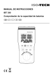
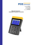
1
Instruction Manual
ISM 490
Solar Module Analyser
GB
F
I
D
ES
TABLE OF CONTENTS / GB
Table of Contents
1. SAFETY INFORMATION ................................................................................... 1
2. PREPARATION .................................................................................................. 4
3. FEATURES ......................................................................................................... 5
4. PANEL DESCRIPTION ...................................................................................... 6
A.
B.
C.
Front Panel ............................................................................................ 6
Rear Panel ............................................................................................. 9
Connecting Wires (Connectors) .......................................................... 10
5. OPERATION ..................................................................................................... 11
A.
B.
C.
D.
E.
F.
Auto Scan ............................................................................................ 13
Manual Scan ........................................................................................ 14
Single Point Test ................................................................................. 16
Save Testing Results........................................................................... 18
Clear recorded testing data ................................................................. 19
Setup Menu ......................................................................................... 20
6. SPECIFICATIONS ............................................................................................ 21
A.
B.
Electrical Specifications ....................................................................... 21
General Specifications......................................................................... 22
7. BATTERY REPLACEMENT / RECHARGING ................................................. 23
8. FUSE REPLACEMENT .................................................................................... 25
9. MAINTENANCE & CLEANING ........................................................................ 27
12/31/09 Version No. 00
SAFETY INFORMATION / GB
1. SAFETY INFORMATION
Read and understand this instruction manual completely before using this instrument.
Failure to observe the warnings and cautions in this instruction manual may result in injury,
death or damage to the instrument and other equipment or property. If this instrument is
used in a manner not specified in these instructions, the protection provided by the
instrument may be impaired
WARNING: Identifies hazardous conditions and actions that could cause
BODILY HARM or DEATH
CAUTION: Identifies conditions and actions that could DAMAGE the
instrument or equipment under test
EN 61010-1:2001 CAT I 60V. Pollution Degree 2
This unit passes the following tests
EN 61326-1: 2006
(CISPR11 Class B, IEC/EN 61000-3-2:2006,
IEC/EN 61000-3-3: 1995+A1: 2001+A2: 2005
IEC/EN 61000-4-2/-3/-4/-5/-6/-8/-11)
GB-1
12/31/09 Version No. 00
SAFETY INFORMATION / GB
EN 61010 Category Definitions
Measurement Application
Category
I
Measurements on circuits not directly connected to the low
voltage installation. (Mains).
Examples include: Measurements on battery powered
equipment and specially protected (internal) mains-derived
circuits.
II
Measurements on circuits directly connected to the low voltage
installation.
Examples include: Household appliances, portable tools and
similar equipment.
III
Measurements performed in the building installation.
Examples include measurements on distribution boards,
junction boxes, socket-outlets and wiring and cables in the fixed
installation.
IV
Measurements performed at the source of the low-voltage
installation. Examples include measurements on primary
overcurrent protection devices and electricity meters
12/31/09 Version No. 00
GB-2
SAFETY INFORMATION / GB
Symbols as marked on the instrument and in this instruction manual
Caution, risk of electric shock
Please read the statement thoroughly to prevent injury or loss of
life, and prevent damage to this product
DC (Direct Current)
Earth (ground)
Conforms to relevant EU directives
Dispose of in accordance with local regulations.
Caution:
1. The ventilation openings on the unit should not be blocked.
2. Please pay attention to polarity of the DC input, follow the polarity
information printed beside the input jack.
This equipment is not for measurements performed on C A T I I , I I I , a n d I V
installations.
Please remove all the test leads before performing maintenance,
cleaning, battery replacement, fuse replacement, etc.
GB-3
12/31/09 Version No. 00
PREPARATION / GB
2. PREPARATION
WARNING. The following safety information must be observed to ensure
maximum personal safety during the operation of this Instrument.
1. To avoid electric shock, disconnect any test leads from the Instrument before
replacing the batteries.
2. When replacing the batteries, do not mix batteries of different types or old
and new batteries.
3. Check the battery polarity carefully when inserting the batteries.
4. Do not short-circuit used batteries, disassemble them, or throw them in a
fire. Doing so may cause the batteries to explode.
5. Dispose of the used batteries in accordance with local regulations.
This Solar Module Analyzer uses rechargeable batteries. Before using new rechargeable
batteries, please charge them first for 10~12 hours continuously for better battery life.
1. Unscrew and remove the battery cover.
2. Fit new rechargeable batteries
3. Replace and screw down the battery cover.
4. Connect the AC Adaptor.
5. Turn on Solar Module Analyzer and press BATTERY CHARGE button to start battery
charging.
6. During recharging, LCD displays “Power: Charge”.
7. It takes at least 10~12 hours to charge batteries. Please do not interrupt the charging
process during this period.
12/31/09 Version No. 00
GB-4
FEATURES / GB
3. FEATURES
z
I-V Curve Test for Solar Cell.
z
Single Point I-V Test.
z
Maximum Solar Power (Pmax) search by auto-scan.
z
Maximum Voltage (Vmaxp) at Pmax.
z
Maximum Current (Imaxp) at Pmax.
z
Voltage at open circuit (Vopen).
z
Current at short circuit (Ishort).
z
I-V curve with cursor.
z
Efficiency (%) calculation of solar panel.
z
Scan delay setting. (0 ~ 9999 ms)
z
2
2
Solar panel area setting. (0.001 m ~ 9999 m )
z
2
2
Standard light source setting. (10 W/m ~ 1000 W/m )
z
Min. power setting for alarm function.
z
Built-in calendar clock.
z
Rechargeable batteries with built-in charging circuit.
z
RS232C (to USB Bridge) cable for PC.
z
Mains adaptor with Euro IDC lead and UK converter plug.
z
Option: 300XP portable thermal printer to print the LCD displays of the Solar
Module Analyzer.
GB-5
12/31/09 Version No. 00
PANEL DESCRIPTION / GB
4. PANEL DESCRIPTION
A.
Front Panel
11
12
9
13
10
14
1
15
2
16
3
17
4
18
5
6
19
20
7
8
12/31/09 Version No. 00
GB-6
PANEL DESCRIPTION / GB
1. F1 button:
(Reserved)
2. F2 button:
(Reserved)
3. BATTERY CHARGE button:
When Solar Module Analyzer is turned on, press BATTERY CHARGE button to
recharge batteries (do not use non rechargeable batteries for recharging).
4.
(buzzer) button:
Press this button to turn on/off the beeper (low power) alarm function.
5. I/V/P SELECT button:
Select display of I-V/V-I curve, P-V/P-I curve, or both curves.
6. TEST button:
Single point I-V test based up specified value.
7. SCAN button;
Manual scan I-V curve test based upon specified value.
8. AUTO SCAN button:
Auto scan I-V curve test.
9. LCD:
LCD displays measurement data and curves.
10. SETUP button:
Enter/Exit SETUP menu.
11.
button:
(1) In a curve, press it to move the cursor left.
(2) In SETUP menu, press it to decrement value by 1.
12. ▲ button
In the SETUP menu, press ▲ button to select previous item.
13. ▼ button
In the SETUP menu, press ▼button to select next item.
GB-7
12/31/09 Version No. 00
PANEL DESCRIPTION / GB
14.
button:
(1) In a curve, press it to move the cursor right.
(2) In the SETUP menu, press it to increment value by 1.
15. BEGIN button:
Start scanning point (current) setting.
16. END button:
Stop scanning point (current) setting.
17. REC button:
(1) Record the present measurement data.
(2) To clear recorded data: press and hold the REC button and turn on the analyzer,
all the data recorded in the analyzer will be deleted.
18. GRAPH GRID button:
Display/Cancel graph grid.
19. I/V CURVE button:
Select I or V as horizontal coordinate.
20. Power button:
Turn on/off the power of Solar Module Analyzer.
12/31/09 Version No. 00
GB-8
PANEL DESCRIPTION / GB
B.
Rear Panel
1
2
3
4
1. Communication Window:
To connect Solar Module Analyzer with PC via USB interface cable.
2. Stand.
3. Battery cover.
4. Battery cover screw.
GB-9
12/31/09 Version No. 00
PANEL DESCRIPTION / GB
C.
Connecting Wires (Connectors)
1. T+ Terminal (Kelvin Clips).
2. T- Terminal (Kelvin Clips).
3. Terminal Reserved for Factory Test.
4. Power input for the AC adaptor.
5. I+ Terminal (Crocodile Clips).
6. I- Terminal (Crocodile Clips).
7. V+ Terminal (Crocodile Clips).
8. V- Terminal (Crocodile Clips).
12/31/09 Version No. 00
GB-10
OPERATION / GB
5. OPERATION
Warning: when the “Overheated” warning is shown in LCD
observe the following procedure:
1. Do not start the next simulation until the “Overheated; cooling” cycle has finished.
2. Wait at least 3 minutes before switching off the instrument to allow the cooling fan to
cool the internal components
GB-11
12/31/09 Version No. 00
OPERATION / GB
Fig. 1 Connecting Diagram
Kelvin Clip Connecting Diagram
Crocodile Clip Connecting Diagram
12/31/09 Version No. 00
GB-12
OPERATION / GB
A.
Auto Scan
1.
Users should first select AUTO SCAN to obtain a general idea of the
characteristics of a solar panel.
2.
Use the Kelvin clips or crocodile clips to connect the solar module to the Solar
Module Analyzer (See Fig.1 Connecting Diagram)
3.
Illuminate the solar module uniformly with an available light source (e.g. direct
sunlight, halogen lamp, xenon lamp, tungsten lamp…)
4.
Press
(AUTO SCAN) button to perform Auto-scan.
After the scanning is finished, the results will be displayed as shown below.
The unit automatically measures the followings parameters: Vopen, Ishort,
Pmax, Vmaxp, and Imaxp. Based upon these parameters, the unit runs a
simulation and plots I-V / V-I curve and P-V / P-I curves on the LCD.
5.
Users can move the cursor to review individual values along the curve.
There is a time delay before the unit performs the “Auto Scan”.
This time delay allows the light source to be turned on before
“Auto Scan” starts. The time delay can be set in the SETUP
menu.
Note: If the short circuit current (Ishort) exceeds 6A, Auto Scan will not be
performed. Please select Manual Scan and limit the ending value of scan to
be less than 6A.
GB-13
12/31/09 Version No. 00
OPERATION / GB
B.
Manual Scan
After completing an AUTO SCAN a specific current range can be tested using
MANUAL SCAN.
1. Use the Kelvin clips or Crocodile clips to connect the solar module to the Solar
Module Analyzer (See Fig.1 Connecting Diagram)
2. Press
button to enter the SETUP menu.Then, set up “Current Range of
Scan begin” and “Current Range of Scan end” parameters.
After setting up the current range, press
button again to exit the SETUP menu.
Note: If the “Current Range of Scan begin” is greater than “Ishort”, then the scanning
will not be performed.
3. Illuminate the solar module uniformly with an available light source (e.g. direct
sunlight, halogen lamp, xenon lamp, tungsten lamp…)
4. Press
button to start MANUAL SCAN. After the scanning is finished, the
results will be displayed as shown below.
12/31/09 Version No. 00
GB-14
OPERATION / GB
There is a time delay before the unit performs the
“Manual Scan”. This time delay allows the light source
to be turned on before “Manual Scan” starts. Time
delay can be set in the SETUP menu.
GB-15
12/31/09 Version No. 00
OPERATION / GB
C.
Single Point Test
A specific test current can be set using the Single Point Test
1. Use the Kelvin clips or crocodile clips to connect the solar module to the Solar
Module Analyzer (See Fig.1 Connecting Diagram)
2. Press
button to enter the SETUP menu
Then, set up the parameters for Single Test Point.
After setting the single point test current, press
button again to exit the SETUP
menu.
3. Illuminate the solar module uniformly with an available light source (e.g. direct
sunlight, halogen lamp, xenon lamp, tungsten lamp…)
4. Press
button to start a Single Test. After the testing is finished, the results
will be displayed as shown below. The result (P, V, I) is shown in reverse video as
below:
12/31/09 Version No. 00
GB-16
OPERATION / GB
Time delay in the “Single Point Test” allows the current
simulation to last longer. Although the max. value is 9.999
sec., the time delay is changed to 10 msec. if the power is
over 100 W. The time delay is extended to 3 seconds if
power is less than 100 mW.
GB-17
12/31/09 Version No. 00
OPERATION / GB
D. Save Testing Results
On completion of an Auto-scan, Manual-scan or Single Point test, press
(REC)
button to save the (present) test results in the memory of the analyzer.
REC:1 (in reverse video) is displayed in the top right of the display to indicate that the
first record was saved.
Please use the application software provided with the
Analyzer to read the saved testing results.
(refer to the software manual)
12/31/09 Version No. 00
GB-18
OPERATION / GB
E. Clear recorded testing data
Press and hold the
(REC) and turn on the Analyzer at the same time; all the data
recorded in the Analyzer (memory) will be deleted.
After performing this CLEAR function, all the recorded data in
the Analyzer (memory) will be deleted completely and can not
be restored. If it is necessary to keep the testing data, please
use the application software to download and save them
before deleting them from the Analyzer. (refer to the software
manual)
GB-19
12/31/09 Version No. 00
OPERATION / GB
F. Setup Menu
1. Press
2. Press
(SETUP) button to enter the Parameter Setting screen.
or
buttons to select the setting items.
(1) Time delay before scan.
(2) Current Range of Scan begin.
(3) Current Range of Scan end.
(4) Area of Solar Cell or Panel.
(5) Irradiance.
(6) Single Test Point.
(7) Alarm of Low Power.
3. Press
or
buttons to change the setting values,
or press and hold the button to promptly change setting values.
4. After setting the parameters, press
12/31/09 Version No. 00
button to exit the SETUP menu.
GB-20
SPECIFICATIONS / GB
6. SPECIFICATIONS
A.
Electrical Specifications
(23℃±5℃, Four-wire Measurement)
DC Voltage Measurement
Range (60V / 6A)
Resolution
Accuracy
0~6V
0.001 V
± 1 % ± (1 % of Vopen ± 9 mV)
6 ~ 10 V
0.001 V
± 1 % ± (1 % of Vopen ± 0.09 V)
10 ~ 60 V
0.01 V
± 1 % ± (1 % of Vopen ± 0.09 V)
Vopen: open circuit voltage of solar cell or module.
If crocodile clips are used to measure voltage only (I+ clip is not connected), clips (Vand I-) must be shorted together. Thus, 4-wire measurement is converted to 2-wire
measurement.
DC Current Measurement
Range (60V / 6A)
Resolution
Accuracy
0.01 ~ 0.6 A
0.1 mA
± 1 % ± (1 % of Ishort ± 0.9 mA)
0.6 ~ 1 A
0.1 mA
± 1 % ± (1 % of Ishort ± 9 mA)
1~6A
1 mA
± 1 % ± (1 % of Ishort ± 9 mA)
Ishort: short circuit current of solar cell or module.
Internal resistance at Ishort: 0.05 Ohm.
Ishort is measured with internal resistance, circuit resistance, and test lead resistance.
GB-21
12/31/09 Version No. 00
SPECIFICATIONS / GB
DC Current Simulation*
Range (60V / 6A)
Resolution
Accuracy
0.01 ~ 1 A
0.1 mA
± 1 % ± 0.9 mA
1~6A
1 mA
± 1 % ± 9 mA
If the current is greater than 6A, the Auto-Scan, Manual-Scan, or single point test
cannot be performed.
Maximum duration of simulation is 9.999 seconds if power is less than 100 W.
Duration of simulation is 10msec if power is greater than 100 W.
B.
General Specifications
Battery Type:
Rechargeable, 2500mAh (1.2V) x 8
AC Adaptor:
AC 110V or 220V input,
DC 12V / 1 ~ 3 A output
Dimension:
257(L) x 155(W) x 57(H) mm
Weight:
1160g / 40.0oz (batteries included)
Operation Environment:
0 oC ~ 50 oC, 85% RH
Temperature Coefficient:
0.1% of full scale / oC
o
o
(<18 C or >28 C)
Storage Environment:
-20 oC ~ 60 oC, 75% RH
Supplied Accessories:
User Manual x 1, AC adaptor x 1
RS232C (to USB Bridge) cable x 1
Rechargeable batteries x 8
Software CD x 1, Software manual x 1
Kelvin clips (6A max) x 1 set
12/31/09 Version No. 00
GB-22
BATTERY REPLACEMENT / RECHARGING / GB
7. BATTERY REPLACEMENT / RECHARGING
When non-rechargeable batteries are used and the LCD displays the Power as ≦2%,
please replace the batteries:
1. Turn off the Solar Model Analyzer.
2. Disconnect all test leads from the instrument
3. Remove the screw of the battery cover.
4. Lift and remove the battery cover.
5. Remove the old batteries and insert eight new 1.5V SUM-3 batteries.
6. Refit the battery cover and secure the screw.
GB-23
12/31/09 Version No. 00
BATTERY REPLACEMENT / RECHARGING / GB
When rechargeable batteries are used, please follow below steps to charge the
batteries:
1. Connect the AC Adaptor with the Solar Module Analyzer.
2. Turn on the Solar Module Analyzer.
3. Press the BATTERY CHARGE button to start recharging.
4. During recharging (takes 10 hours), LCD displays “Power: Charge”.
5. After recharging, LCD displays “Power: 100%”.
6. Remove the AC Adaptor.
1. Do not attempt to charge non-rechargeable batteries.
2. To prolong battery life recharging only when LCD
displays the Power is ≦2%.
3. To prolong the battery life do not stop interrupt the
charging cycle.
12/31/09 Version No. 00
GB-24
FUSE REPLACEMENT / GB
8. FUSE REPLACEMENT
When the voltage cannot be measured (Vnow = 0V) after properly connecting the Analyzer
and the solar panel, please check the fuse.
If the fuse has failed, replace with a new fuse by the following procedure:
1. Turn off the Analyzer and remove any test leads and power sources.
2. Unscrew and remove the battery cover. Remove the batteries
3. Unscrew the 4 screws of the back cover. Remove the back cover. Remove the power
connector connecting the back cover and the circuit board (J2).
4. Replace the damaged fuse with a new fuse of the same specifications (20mm F; LBC 5A
/ 250V).
5. Connect the power connector. Replace and screw the back cover.
6. Replace the batteries Replace and screw the battery cover.
After removing the battery cover, please do not touch the
parts on the circuit board, especially the communication LED
or the communication function will be damaged.
GB-25
12/31/09 Version No. 00
FUSE REPLACEMENT / GB
Unscrew and remove
the battery cover and
the back cover.
Location of Fuse
12/31/09 Version No. 00
GB-26
MAINTENANCE & CLEANING / GB
9. MAINTENANCE & CLEANING
1. Servicing not covered in this manual should only be performed by qualified personnel.
Repairs should only be performed by qualified personnel.
2. Periodically wipe the case and cable with a damp cloth and detergent; do not use
abrasives or solvents.
3. Please remove all the batteries if the Solar Module Analyzer is not to be used for a long
time
GB-27
12/31/09 Version No. 00
Africa
Iso-Tech
1 & 2 Indianapolis Street
Kyalami Business Park
Kyalami, Midrand, South Africa
Asia
Iso-Tech
460 Alexandra Road, #15-01A
PSA Building
Singapore 119963
Europe
Iso-Tech
PO Box 99
Corby
Northamptonshire
NN17 9RS
United Kingdom
Japan
West Tower (12th Floor)
Yokohama Business Park
134 Godocho, Hodogaya
Yokohama, Kanagawa 240-0005 Japan
USA
7410 Pebble Drive
Fort Worth
Texas 76118-6961
Canada
1701 Woodward Drive
Ste 108 Ottawa
Ontario K2C 0R4, Canada
South America
Av. Pdte. Eduardo Frei M. 6001-71
Centro Empresas El Cortijo
Conchali, Santiago, Chile