1
P325 User Guide
Low EM! Microstep Power/Drive
Installation and User
Reference Manual
AMERICAN PRECISION INDUSTRJES, INC.
CONTROLS DIVISION
4401 Genesee Street
Buffalo, New York 14225
(716) 631-9800
1
GETTING STARTED
Our goal as a supplier is to provide the user with the proper tools to get
his/her application up and running as quickly as possible. This includes
designing
products that
are
easy to
learn, use,
install,
·and maintain,
in
addition to providing the required documentation and support to quickly answer
any questions that you might have. To help you get started, this section will
provide you with a roadmap through this manual. Depending on your level of
expertise, you can decide how to proceed. We hope you find our recommendations
helpful and we welcome any comments/suggestions that you might have in helping
us achieve our goal.
.'
The primary intention of this manual is to guide the first time user of the P325
Series packages through the familiarization and installation into the chosen
application.
After the initial installation is accomplished it can also serve
as an ongoing
needs.
reference manual
for installation
changes or
future reference
While this manual is intended to include as much available information as
possible; it is designed to also be easy to use for those who ~vill not be
reading the entire manUal or who only want to refer to specific sections.
Users
should classify themselves and proceed accordingly:
First time users We recommend that all first time users and those basically unfamiliar with
step
motor
drives
read
the
entire
manual
before
proceeding
with
installation.
Experienced users
Refer to the Precautions
in SECTION 2
and to the
Summary in
SECTION 4
before proceeding with your installation.
Current users with specific information needs
The
comprehensive index
contained in
SECTION 3
will guide
you to
the
specific location with answers to your questions.
2
'
PRECAUTIONS AND WARNINGS
While we have designed these drives with
keep She following precautions in mind:
->
safety issues in mind, the user should
Because potentially hazardous voltages can be present around this drive,
only qualified service and installation personnel should install this
device.
->
All connections or changes to the
drive configuration should be.made with
any power sources turned off and disconnected from the drive.
P325 Operating Manual (Rev 1190)
·Page 1
3
TABLE OF CONTENTS
SECTION
PAGE
1 GETTING STARTED . . . . . . . . . . . . . . . . . . . . . . . . . . . . . . . . . . . . . . . . . . . . . . . . . . . . . . . . 1
2 PRECAUTIONS AND WARNINGS . . . . . . . . . . . . . . . . . . . . . . . . . . . . . . . . . . . . . . . . . . . . . . . 1
3 TABLE OF CONTENTS . . . . . . . . . . . . . . . . . . . . . . . . . . . . . . . . . . . . . . . . . . . . . . . . . . . . . . 2
4 SUMMARY OF OPERATIONS . . . . . . . . . . . . . . . . . . . . . . . . . . . . . . . . . . . . . . . . . . . . . . . . . . 3
5 UNPACKING AND INSPECTION ............................... , . . . . . . . . . . . . . . . 4
6 DESCRIPTION OF OPERATION . . . . . . . . . . . . . . . . . . . . . . . . . . . . . . . . . . . . . . . . . . . . . . . 5
7 MOTOR COMPATIBILITY . . . . . . . . . . . . . . . . . . . . . . . . . . . . . . . . . . . . . . . . . . . . . . . . . . . . 6
8 DRIVE CONFIGURATION AND CONNECTIONS ....................................
8.1 Drive Configuration ...............................................
8. 1. l Introduction ......... , . . . . . . . . . . . . . . . . . . . . . . . . . . . . . . . . . . . . .
8. l. 2 Low Voltage Adjustment .....................................
8. l. 3 Current Switch Settings .. . .. .. . .. .. .. . .. .. .. .. .. .. .. .. .. . ..
8. l. 4 Current Profile Settings .. . .. .. .. .. .. .. .. .. .. .. . .. .. .. .. .. .
8 .l. 5 Micro step Resolution Switch Settings .......................
8. 2 Drive
8. 2 .l
8 . 2. 2
8.2.3
8. 2. 4
7
7
7
7
8
9
9
Connections . . . . . . . . . . . . . . . . . . . . . . . . . . . . . . . . . . . . . . . . . . . . . . .
Introduction ..............................................
Motor Connections . . . . . . . . . . . . . . . . . . . . . . . . . . . . . . . . . . . . . . . . .
Logic Connections .........................................
Power Connections . . . . . . . . . . . . . . . . . . . . . . . . . . . . . . . . . . . . . . . . .
10
10
10
11
12
9 INSTALLATION . . . . . . . . . . . . . . . . . . . . . . . . . . . . . . . . . . . . . . . . . . . . . . . . . . . . . . . . . .
_9_,_! Cool~ . . . . . . . . . . .. . . . . . . . . . . . . . . . . . . . . . . . . . . . . . . . . . . . . . . . . . . . . . .
9 . 2 Mounting . . . . . . . . . . . . . . . . . . . . . . . . . . . . . . . . . . . . . . . . . . . . . . . . . . . . . . . .
9. 3 Drive Configuration .............................................
9. 4 Drive Connections . . . . . . . . . . . . . . . . . . . . . . . . . . . . . . . . . . . . . . . . . . . . . . .
9. 5 Applying Power . . . . . . . . . . . . . . . . . . . . . . . . . . . . . . . . . . . . . . . . . . . . . . . . . .
12
12
12
13
l3
l3
10 PERFORMANCE EXPECTATIONS ............................................. 14
11 P325 SPECIFICATIONS . . . . . . . . . . . . . . . . . . . . . . . . . . . . . . . . . . . . . . . . . . . . . . . . . . 15
12 TROUBLESHOOTING . . . . . . . . . . . . . . . . . . . . . . . . . . . . . . . . . . . . . . . . . . . . . . . . . . . . . . 16
13 VELOCITY CONTROL OSCILLATOR OPTION (P325V) ...........................
13. 1 Description . . . . . . . . . . . . . . . . . . . . . . . . . . . . . . . . . . . . . . . . . . . . . . . . . . . .
13.2 P325V Logic Connections .......................................
13.3 Adjustments ....................................................
13.4 VCO Specifications .............................................
18
18
18
20
21
14 APPENDIX A
API Motor Listing ....................................... 22
15 APPENDIX B
Dip Switch Settings ..................................... 23
16 APPENDIX C
Performance Curves . . . . . . . . . . . . . . . . . . . . . . . . . . . . . . . . . . . . . . 25
P325 Operating Manual (Rev 1190)
Page 2
4
SUMMARY OF OPERATIONS
This section
is provided only
motor drives or wish
Series step motor drives.
], .
for those who
either have experience
to learn the minimum required to hook-up
An assumption is
train available to supply to the drive.
manual should be referred to as required.
with step
and run the P325
made here that the user has a pulse
If not, then
other sections
of the
The P325 Series is a bilevel voltage step motor drive with microstepping
capability.
By microstepping a step motor,
its motion can be dramatically
smoothed and the positioning resolution greatly enhanced without sacrificing its
other attractive features.
Microstepping involves taking each of the motor's
mechanical full steps and electrically creating many finer ones by precisely
controlling the current flow to each of the windings.
The P325 series will
drive 4-phase motors rated at up to 4.0 Amps per_ phase (bifilar rating).
The
basic installation steps include:
-~
1)
2)
3)
4)
5)
6)
7)
8)
9)
10)
Ensure that the AC power source is 115 VAG.
.Read Section 8 - Drive Configuration and Connections
Ensure the Low Voltage Adjustment is properly set (Section 8.1.2)
Ensure that the drive current switch s~ttings are set for the motor
that you are running (Section 8.1.3).
Verify the Current Profile Settings (Section 8.1.4).
Select the Microstep Resolution desired (Section 8.1.5).
Plug the motor connector into the socket labeled motor (Section 8.2.2).
Connect the required logic control lines (Section 8.2.3).
Plug into your power source (Section 8.2.4).
Supply control signals to the drive. The type of control utilized to
supply step, direction and other control signals to the drive depends
on the application and the available equipment. Methods offered by the
Controls Division include the VCO option on the P325 (Section 13), and
the SAC-560 Smart Axis Controller. Another option is for the user to
supply the required signals directly from his system. A brief synopsis
of each option follows:
CONTROL SIGNALS:
USER INPUT
This is a valid option when the user system already contains a
computer or programmable logic controller.
With this method, the
user provides TTL inputs directly to the step motor drive to control
motion in the
system.
As a bare minimum, step
and depending on the
application direction inputs must be provided to the step motor
drive. Additionally, many applications will require efficient ramp
routines to achieve the performance
the responsibility
control.
of the user when
objectives of the system.
this is the selected
It is
method of
SAC-560
Select this option when the user's system does not contain a logic
device; the motion·sequences are complex; the motion sequences are
changing frequently;
or if performance requirements are demanding.
The SAC-560 is a self-contained, high speed microprocessor based
controller.
Features include RS-232 communications, programmable
inputs and outputs that interface to external devices,
and an
English-like command language.
Ramping routines are automatically
generated and/or can be placed under user control.
P325 Operating Manual (Rev 1190)
Page 3
VCO OPTION (P325V)
Select this option when motion in the system is fixed and logic is
available to provide for timing of the Run, Accel, Decel and Stop
signals required by this device.
When signals are received, the VCO
board will generate pulses to the motor at the rate established by
the onboard Base, Slew, Accel and Decel potentiometers.
These
potentiometers are preset by the user and require manual adjustment,
(Section 13).
5
UNPACKING AND INSPECTION
Carefully remove the contents of the carton in which the driver was shipped.
Inspect the carton and the drive and make note of any apparent physical damage.
If severe damage is present then you should consider rejecting the shipment and
making coritact with the shipping company concerning in-transit damage claims.
We have made every effort at the factory before shipment to fully inspect, test,
and properly package this product so that it reaches you defect free and without
damage.
·
All packaging materials should be saved and set aside in case a return
has to be made.
The con.tents may include connectors, mounting screws,
or other components - please compare these components to the parts list
included on the shipper.
Immediately report any discrepancies to the
location.
·
P325 Operating Manual (Rev 1190)
Page 4
shipment
a motor,
which is
shipping
6
DESCRIPTION OF OPERATION
Functional Overview
The P325 Series are driver and power supply units that combines bilevel voltage
drive technology with an integral linear power section.
Each model includes a
motor, drive, linear power supp-ly, integral heatsink, power cord, connectors and
a full enclosure.
The P325 Series packages are directly compatible with the
Controls Division's Indexers/Controllers for a total motion system solution.
All models contain the logic and power switching stages required to operate a
large percentage of existing step motor designs. The logic section of the drive
acts to direct current in and out of the motor phases in a proper sequence in
order to cause the desired rotation.
The power switching stage controls the rate
and amount of current flow into the
motor windings as directed by the logic.
In general, the faster the current is
pumped through a winding during each step, the more torque and speed that will
be obtained. The P325 Series uses a bilevel voltage method of current control
which will yield excellent speeds and torques.
This technique involves
overdriving the windings with a high voltage to decrease the current rise times,
and then reducing the voltage to provide a constant current to the motor
windings ..
..
: ,
The inputs to the drives have been designed to
Section 8 for technical descriptions):
handle many configurations (see
Power
The required AC power is 115 Volts, 60 Hz.
5 VDC, 100 milliamps for the optically isolated inputs.
Motor
Either 6 or 8 lead hybrid motor leads can be connected to the drive.
Section 7 for details)
(See
Pulse Source
The P325 Series accept pulse and_ direction control inputs from a wide
variety of sources.
See Section 4 for optional methods of supplying
control signals to the drive. The maximum rate of pulses accepted is 1.0
MHz, or 1,000,000 pulses per second.
Other Control Features
.The no-power input is used to control a power down state, disabling the
motor. The low~power input is used to reduce the current to one-third
full power.
The microstep resolution,
current profile and current
supplied to the motor are controlled by setting dip switches on the drive.
P325 Operating Manual (Rev 1190)
Page 5
7
MOTOR COMPATIBILITY
The P325 Series is capable of running a wide _range of step motors with it sbilevel voltage switching technique. The limits of these ranges fall into
1
several categories:
Winding Type
The motor winding type should be basically a four phase motor which is
capable o"f unipolar operation, characterized by the need for current to
flow in only one direction in each coil of the motor. Most motors which
fall into the "HYBRID" motor classification will work. Step angles of 0.9
and 1.8 degrees are the most common. Other step angles will also work.
Appendix A lists the most common motors available through the Controls
Division of API.
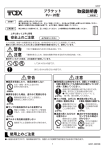
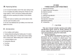
Number of Leads
Hybrid style motors have 4, 6, or
8 leads depending on how they are wound
and connected.
these 3 basic configurations; note that
Diagram 7.1 shows
the 4-lead motor is wound in a "UNIFILAR" fashion while the 6 and 8 lead
motors are wound in a "BIFILAR" fashion.
ONLY 6 OR 8 LEAD WINDINGS CAN BE
OPERATED.
:Jg
3
YEL
MOTOR
y /l,/
"ll
"'
"' "' "'il
...J
6 LEAD BIFILAR MOTOR
'
D
'
0
8 LEAD BIF!LAR MOTOR
DIAGRAM 7.1
Motor Current Rating
The basic current output range
_lating.
Inductance
The minimum
m~tor
is
inductance of .SmH
.9 to
4.0 Amps
per phase,
bifilar
bifilar is required on all models of
drives for the power switching stage to be able to control currents.
Size
Recommended motor sizes for the P325 Series is size 17 to size 42 motors.
(see Appendix A).
Other controlling factors are the motor's current
rating, inductance and winding type.
If a question remains about whether a particular motor can be operated, please
contact the Controls Division for application assistance.
P325 Operating Manual (Rev 1190)
Page 6
8
DRIVE CONFIGURATION AND CONNECTIONS
8.1
Drive Configuration
8 .l.l
Introduction
To provide the user with the greatest amount of versatility,
four adjustments
can be made to configure the drive for the application. The first adjustment,
selection of the low voltage tap.on the transformer, sets the drive for the
voltage rat.ing of your motor'. The second and third adjustments are dip switch
settings which tell the driver the current rating of the motor and the optimum
current profile for your motor.
The fourth setting establishes the microstep
resolution desired.
Depending on how you ordered, the drive may have already been set for a specific
motor or to standard default conditions which
require you to go through a setup
process for your specific applica-tion and motor.
The
setting will
Examine· the label.
be found
on· a
If. a motor. is
label affixed
to the
drive at
the factory.
listed and corresponds to the selected motor,
then continue with the microstep resolution switch settings,
(Section 8.1.5).
If the listed motor differs or if no label can be found, follow the procedures
in this section to verify and adjust the settings, disconnect power before
proceeding. After making any adjustments, be sure to note of them for future
reference.
8.1.2
Low Voltage Adjustment
The P325 has the capability of running any hybrid (1.8 degree) step motor with
ratings from 1 - 4.0 amps per phase.
Two settings must be made to configure the
driver to the power rating of the motor.
second is the motor current rating.
The
fi~st
is the motor voltage and the
With the drive enclosure removed; a transformer will be located with four spade
lugs protruding from one end numbered; 1, 2 and 3. To configure the drive to
th~
motor being used, you must attach
the
11
BLUE 11 wire to the proper low-voltage
lug (see Figure 8.1.2 for location).
Consult APPENDIX A,
intend to drive and its corresponding low-voltage lug.
If
you intend
to run
a motor
not listed
in APPENDIX
for the
A, please
factory for appropriate instructions.
u
0
3 2 1
0
0
Figure 8.1.2
P325 Operating Manual (Rev 1190)
Page 7
motor you
consult the
8 .1. 3
Current Switch s·ettings .
If your drive and motOr were purchased together as a package, then the current
settings should have been· ·previously made by • your supplier.
It: is still
advisable to verify that the .settings are correct prior to applying power to the
drive.
Before making connectiOns·· to the drive, the current setting for the motor's
rated current per phase should be determined and set at the 8 position DIP
switch located on the logic board (see Diagram 8 .1. 3 for location).
Current Settings
Amps per
Phase
1.6
0.8
0.4
0.2
0.1
NOTE 1 -
Switch (NOTE 1), (NOTE 2)
Block ffo2
12345678
10000
01000
00100
00010
.00001
See DIAGRAM 8.1.3 for location of Switch Block #1.
A 11 0 11 indicates that
switch is 11 0N 11 •
NOTE 2 ·
the switch is
11
0FF 11 and a
11
1" indicates the
The nominal current is 0.9 amps/phase with switches
#2 turned OFF. Drive output current is the sum of
l-5 plus 0.9 amps/phase.
POT, ADJ.
cvco
~BASE SPEED
P2 ~MAXIMUM
SPEED
P3 ~RAMP RATE
P4~ SYMMETRY
Pl
P5~
S'W2
S'Wl
I[COOOCQJIIOJOODCODI
l\IOTE S\./3 IS LOCATED ON THE RIGHT
SIDE OF THE P325 SERIES DRIVE.
P325 Operating Manual (Rev 1190)
Page 8
l-5 on block
the switches
OPTIO~D
If no·t kriown the user should determine ·the current per phase rating of the motor
to_ be used and whether or not the rating meets the drive requirements.
Once the motor part number ~nd current rating is known, refer to Appendix A or B
to dete~mine the closest listed current setting.
If the closest current is
within 10% of the rated current, it will probably suffice for most applications.
Current settings greater than 10% more than the rated value should not be used
unless special
cooling precautions are
taken or intermittent
operation allows
for liberal use of the Low Power state. These precautions should preclude motor
temperatures greater than the maximums spec.ified by the manufacturer. By using
a ball point pen or pointed object, duplicate the switch settings given in the
Appendix at the DIP switch on the drive. DO NOT switch the settings with power
applied to the motor.
·8.1.4
Current Profile.Settings
After selecting
the proper low-voltage tap and current for the rating of the
motor, you must select a current profile which is optimum for the motor. This
is done by dip
switch #2, see Figure 8.1.3 for
location.
Reference APPENDIX A
_for the values, and set the switches as indicated.
8.1.5
•·.l
Microstep Resolution Switch Settings
The P325 Series drive allows the the
resolution that best matches his
user the versatility to select a microsteg
application requirements.
For a standard 1.8
step motor there are nine selectable resolutions that range from 200 to 25,600
steps per revolution. Refer to APPENDIX B and determine the resolution that
best meets your needs and set the swithces as indicated.
The user may wish to record the drive configuration settings
in the table
provided below before proceeding to the section on drive connections.
The drive
may be closed at this time as further internal adjustments are not required.
P325 Configuration Settings
Motor Model
Current Setting
Voltage Tap
Step Resolution
Date: _ _ __
12345678
. Switch Block fll
Switch Block 112
Switch Block /13
Notes:
P325 Operating Manual (Rev 1190)
Page 9
8.2
Drive Connections
8.2.1
Introduction
This section will list and explain all the connections to the P325 Series drives
·which includes motor
logic and power connections.
1
Notation and Conventions
All available logic inputs have two possible input states which will be referred
to as
11
High" and
11
by default since
LOW 11
When a logic terminal is open it
•
is in a
High 11 state
it is clamped "High" internally with
notation which uses the
11
bar
11
a pull-up resistor. Any
convention will assume that the state indicated by
the bar is activated by taking that
logic terminal "Low" (ie.
CC1.] direction of rotation when taken
11
Connector
11
- CW/CCW denotes
Low 11 ) .
~
Three plug type connectors allow the
user to make the necessary connections via
terminals which control a clamping action on the bare wire of
It is recommended that connections be made prior to plugging into
recessed screw
each input.
the drive.
NOTE: l.)Motor Connections are made on the 7 pin connector.
2.)Logic Connections are made on the 8 pin connector.
3.)Power Connections are made on the 3 pin connector.
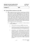
8.2.2
Motor Connections
MOTOR CONNECTIONS (7 PIN CONNECTOR)
MOTOR LEAD TERMINALS (Terminal #'s 1-7)
The leads from the chosen motor will. be connected at some or all of these
terminals.
Diagrams showing the possible connections for 6 or 8 lead motors.
MOTOR
I
I
>
'
~
MOTOR
:l
?
I
7 I
I
I
w
~
I _I
I
>
A
ili
"'
"
0
~
~
"
~
~
$
I
6 LEAD MOTOR
•"
~
8 LEAD MOTOR
CAUTION: Do not supply power to the drive without having all of the motor leads
firmly connected to their appropriate terminals.
P325 Operating Manual (Rev 1190)
Page 10
8.2.3
Logic Connections
The logic inputs required by the P325 a:re made on .the 8 pin connect:or and
plugged into the drive section labeled 11 LOGIC' 1 •
All Logic inputs can be
optically isolated by providing a 5 VDC source.
Each of the logic inputs is clamped "High" internally with a pull-up resistor
and. requires the user's controller to pull them 11 LOW 11 to return of the 11 0PTO IN 11
supply. Each of the user's control lines should be capable of sinking. at least
15 rna. The optical isolation feature electrically isolates the motor and power
stages of .the drive in order to protect both circuits and eliminate electrical
noise problems.
GROUND (Terminal 1)
This terminal is the reference ground for the +5V OUT supply. This reference
ground should be only be connected to the ground of· the users controller when
the optical isolation feature is defeated.
STEP INPUT (Terminal 2)
The motor will be instructed to step
pulse up to
seconds.
a rate
of 1
MHz. The
on the rising
minimum input
DIRECTION (Terminal 3) - "CW/CCW"
A 11 High 11 or open connection on this terminal
edge of
would cause a
rotation of the motor as viewed from the output shaft end.
the direction
switched
will be
while the
counterclockwise (CCW).
motor
is rotating,
but
The
each incoming
pulse width
is 1
Clockwise (CW)
When ta.ken
direction input
may cause
the
micro
11
Low",
may be
motor to
lose
synchronism if operating above it's Start/Stop torque capability.
LOW POWER (Terminal 4) - "HI/LOW POWER"
This input allows the user to reduce the power to the motor to one-fourth of
the high current setting.
The "High" or open state provides full current to
the motor.
When taken 11 Low 11 , the current is reduced to 25% of it's full
rated power.
This may be used to maintain-a holding current on the motor or
to help reduce motor heating.
POWER ENABLE (Terminal 5) - "ENA/NO POWER"
This input allows the user to cut off power
to the motor on
command.
The
High,. or open state allows normal stepping of the motor at it's rated
current. When taken 11 Low 11 , all power is cut to the motor for the duration of
the 11 LOW 11 state.
Incoming step pulses are ignored when this line is held
"Low 11 • Normally this input is used to issue an emergency stop command to the
motor.
11
NO CONNECTION (Termminal 6) - "NC"
This terminal is not connected internally.
OPTO INPUT (Terminal 7) - "OPTO IN"
The user must provide +5 VDC here t:o operate the optical isolation feature of
the P325. The optical isolation feature will be defeated if the user chooses
to use the on-board +5 VDC supplied by the P325 drive on logic terminal #8.
+5V OUT (Terminal 8)
This terminal can be jurnpered to "OPTO IN" to defeat the optical isolation
feature.
This output should not be used to drive any external loads as
damage to the drive may result.
P325 Operating Manual (Rev 1190)
Page ll
8.2.4
Power Connections
Ensure that your power source is '115 VAC, 60Hz.
A three prong power cord with a 3 pin plug type connector is provided with the
package. Simply plug the connector into the mating socket on the drive and plug
into the power source.
When power is present,
the green LED will be
illuminated.
Pin out list follows:
AC Input Black
AC Input White
AC Input Green
LED indicating
9
Wire (Line) ........ Line
Wire (Neutral) .... , .Neutral
Wire (Ground) ....... Ground
power on ........... Power
INSTALLATION
The contents of this section will guide the user through the proper steps
required to safely install and hook-up the P325 Series drivers.
This section
should be read in it's entirety
the installation process.
9.1
for first-time installers and
reviewed during
Cooling
The base of the P325 is a heatsink which allows for heat dissipation produced by
the internal components.
During operation the heatsink will become warm to the
touch and should not be a concern to the user.
Additional air cooling devices
are not required except where ambient temperatures are high or high current
motors are used.
Consult the factory if these conditions exist.
The most fundamental rule to follow concerning pro.per cooling of the drives is
to keep the heatsink surface temperature less than 65°C.
Since the drive is
convection cooled, it is recommended that you- allow a minimum of one inch on all
sides for air flow.
Operating in an enclosed area may require external cooling
in order to keep the heatsink temperature less than 65°C (ie.
- forced air
fan).
For a rule of thumb if you are not able to measure the heatsink
temperature, the heat sink temperature is within limits if you can comfortably
hold your finger on it more· than 3 seconds.
9.2
Mounting
The P325 is a self-contained package requiring minimal concern for mounting
methods and positions. A dimensional outline of the P325 is given in Figure
9.2.
Flanges with mounting holes have been provided to mount or secure the
B325. The recommended mounting position is vertical with the heatsink exposed
to allow convection and heat removal from the drive.
The user should refrain
from mounting where the heatsink is unexposed or where easy access to the
connectors or adjustments is not practical.
In general,
the drive should be positioned close to the motor although step
motors are fairly tolerant of long lead lengths. Should the drive need to be
positioned more than 6 feet from the motor, consult the factory for the
availability of motors with longer lead lengths.
P325 Operating Manual (Rev 1190)
Page 12
'
earn
9.50
r
.161 0\A
6 PLAC(
~I
SID€.
•
FRONT VIEW
'
10.00
I
.25
I
I
•
SIDE VIEW
~
"
·~
1,., •
~
~
-
I
•
I
8
N
lil
9
ill
~
.I
1
Figure 9.2
9.3
Drive Configuration
9.4
Drive Connections
Motor Connections
Motor connections are made on the 7 pin pluggable connector provided with the
drive.
If you purchased the drive with a motor, then the motor connections and
current switch
settings will
already have
been made.
If
not,
then
refer to
Section 8 Appendix A and Appendix B for the proper drive settings.
Logic Input Connections
The minimum
logic connection required to
operate the P325 Series
drive is the
pulse input. All other inputs will default to their "High" states during
operation. If other states are require!i then the ability to take them "Low"
should be available. Refer to the terminal descriptions in Section 8.2.3 to
determine the required inputs.
Logic input
connections are made through
use of an 8
pin pluggable connector.
The connector may be pulled out by applying a force st~aight away from the
drive .. · Connect each input by inserting l/4 inch of stripped bare wire into the
socket and tighten the pressure screw until the wire is firmly secured.
9.5
Applying Power
Once the drive is properly mounted and all of the required connections have been
made, the drive may be powered up. Plug the 3 pin mating plug into the drive
and then the power cord into 115 VAG source.
Initial power should be applied
with no pulses being fed to the drive. The motor will lock into position at
it's rated static torque.
Once the
begin to step in the set direction.
any
torque or
will
not properly
pulse input rate begins,
the motor should
At this point, if the motor does not have
rotate,
refer to
Section
12 for
remedies.
P325 Operating Manual (Rev 1190)
Page 13
possible
10
PERFORMANCE EXPECTATIONS
S.tep motors are quite unique in many aspects of their design, performance and
control. Many attributes of a step motor can be attractive to the application
designer;
such as their simplicity,
digital nature, and inherent open loop
capability.
Other attributes have to be overcome to allow a step motor to
perform the best in an application; such as resonant instability and loss of
torque as a function of speed.
It turns out that a step motor's driving
electronics play just as important a role in performance as the motor itself.
Since a motor'·s inductance acts to inhibit. current buildup and decay, the faster
that current can be moved, the more that torque producing current will be pumped
through the windings.
A bilevel drive,
such as the P325 Series, is designed to minimize the current
rise times by it's bilevel voltage driving action. The user can expect to
achieve relatively fast stepping rates with these drives running in an open loop
capacity; in general, the lower the inductance of the driven motor (also, the
higher the current rating), the faster the drive will be able to step the motor.
Since all.
step
should try to
rnotq~s
exhibit
resonant instability
minimize their effect by microstepping.
at lower speeds,
The
the user
unstable areas of a
full or half stepped motor are characterized by erratic motion and a severe loss
of torque.
A microstepped motor will exhibit less resonance than a full stepped
motor.
Sample performance curves
a~e
provided in Appendix C for your reference.
P325 Operating Manual (Rev 1190)
Page 14
11
P325 SPECIFICATIONS
General:
Drive Type
4 Phase, bi-level voltage, constant current
Stepping Modes .......... .
Dip switch selectable microstep modes, 200,
400,
800, 1600, 3200, 6400, 12800, 25000,
256.00
Power Requirements:
Input .................... .
100-122 VAG.
60Hz
Output Rating ............ .
.9 to 4 Amps per phase
Dip Switch Selectable
Physical:
Dimensions
4.25"W X 5.0"H X lO.O"L
Weight ................... .
5 lbs.
Temperature:
Storage ................. .
-40° F to +185° F
(-40° C to +85° C)
Operating ............... .
l50°F (65°C) maximum heatsink temperature
Logic Inputs:
Type .................... .
Optical Isolated
with a
separate
supplied+ 5 VDC, 100 milliamp minimum
Level ....................
Logic '1' (HIGH) - 2.0 to 5.0 VDC
Logic '0' (LOW) - 0 to 0.5 VDC
Step . . . . . . . . . . . . . . . . . . . . ..
Step on trailing edge of a square wave
signal.
Requires 1 microseconds minimum
width at a maximum rate of l MHz. TTL
compatible.
Direction
·cw;ccw·
Low Power
"HI/LO POWER"
Reduces motor current to 25% of full power
Power Enable . . . . . . . . . . . . .
user
"ENABLE/NO POWER"
reduces current to motor to zero
Motor:
Motor Connections . . . . . . . . .
P325 Operating Manual (Rev 1190)
Connections for 6, or 8 lead hybrid motors
Page 15
12
TROUBLESHOOTING
If a problem occurs the operator should immediately turn off and disconnect all
power to the drive before attempting any· troubleshooting or repair. Initial
troubleshooting of the· drive should be done with the load disconnected to
isolate the drive from possible load related problems. The following list of
symptoms, causes, and corrections may help to guide the user through a problem
solving session.
MOTOR SHAFT FAILS TO TURN '
No power to drive
check if AC voltage is present by checking
green LED indicator on the drive is illuminated.
Open motor windings - check that each
appropriate resistance with no open coils.
motor
winding phase
if the
has
the
No incoming pulse - check for proper level and width of pulse at Logic Pin
fl2 (Step).
No power logic
check to see that Logic Pin
#S,(ENA/NO POWER) is
11
11
Hirfh
b.
or open.
Low power logic
or open.
Fixed load
check to see that Logic Pin fl4
check to see that driven
(HI/LO POWER) is "High"
load is not jammed or
too large a
load for the chosen motor size.
MOTOR MOTION IS ERRATIC Improper
lead connections
confirm that
the leads
of
the motor
are
connected with the proper sequence._
Winding continuity
- check to
see that each phase
of the motor
has the
appropriate resistance with no shorts between windings or to the housing.
Incoming pulse integrity
confirm that the pulses being supplied to the
driver are the proper level and width and that the rates are not too fast
for the motor to maintain synchronism.
-Resonant instability - confirm that the motor is
resonance range by adjusting the pulse rate.
not
operating in
a
Current profile adjustment - confirm that the dip switches are set for
selected motor. If the problem of rough microstepping persists then the
following procedure is recommended. Adjust the pulse rate to achieve a
shaft speed of one revolution per second, next adjust the de-offset
potentiometers R4 and Rl8 to achieve smooth rotation of the motor shaft,
(see location next page). The adjustment of the de-offset potentiometers
will fine tune the drive to the selected motor.
P325 Operating Manual (Rev 1190)
Page 16
MOTOR RUNS VERY HOT Normal operating mode - it is normal for step motors, .when ·run at their
rated current, to be hot to the touch when operating.
In. general, if the
motor Case teffiperature is less that 85° C., their is no- cause for concern.
Current
set too
high - check to
see
that the
current is
set at
the
appropriate level for the motor being operated .
. MOTOR FAILS DURING ACCELERATION OR ffiliLE RUNNING Irnpi:'oper acceleration rate - check that the increasing rate of pulses feed
to the drive is not too fast for the motor to maintain synchronism with
the driven load.
Erratic loading - if the driven load dramatically changes while motor is
driving, it could overcome the speed/torque capability of sys tern - try to
run the motor with the load disconnected.
No power logic - be sure that Logic Pin {!5 (ENA/NO PO\?ER) is "High".
If all of the above remedies are attempted and the problem still remains,you may
have to return the drive for
servi~e.
For assistance contact
Your local API representative.
Your local Distributor.
or
CONTROLS DIVISION
4401 Genesee St.
Buffalo, NY. 14225
(716) 631-9800
FAX: (716) 631-0152
To return a drive for service Please call the number above to receive a Return
Number.
Material Authorization
You will be instructed at that time where to return the drive for
the most expeditious service.
P325 Operating Manual (Rev 1190)
Page 17
"T3
VELOCITY CONTROL OSCILLATOR OPTION· (P325V)
13.1
Description
For .applications requiring only the start/stop and direction control of· the·.
motor, the P32SV is equipped with a pulse generator capable of 1 to 1,000,000
pulses· per. second with built- in acceleration and deceleration capability. In
essence, the motor will start at a BASE SPEED when the STOP/RUN input is taken
11
LOW 11 • After a subsequent ACCEL input is taken 11 Low", the motor will acce.lerata
to ·an MAXIMUM SPEED. The CLOCK OUT output is available for the user to monitor
the number and frequency of pulses taken.
When the upper speed is reached, the output AT SPEED, terminal ffl"O ·becomes a
logical 11 Low 11 signal available to the user ... This signal can drive one low pmver
TTL load with a maximum capacitance of 15 picofarads.
The motor will decelerate to the base speed with a logical "High" or open at the
ACSEL inpu:t, and a subsequent "High" or open at the STOP/RUN input will bring
the motor to a halt.
The acceleration and deceleration rates, upper speed and
base speeds are adjustable by the user thru potentiometers on the drive.
13.2
P325V
Logic Connections
The logic inputs required by the P325V are made on the 12 pin connector and
plugged into the drive section labeled "LOGIC".
All Logic inputs can be
optically isolated by providing a 5 VDC source.
Each of
the logic inputs is
clamped "High" internally with
a pull-up resistor
11
and requires the user's controller to pull them 11 Low" to
0PTO IN 11 supply
return.
Each of the user's control lines should be capable of sinking at least
16 ma.
The optical isolation feature
electrically isolates the motor and power
stages of the drive in order to protect both
noise problems.
circuits and eliminate electrical
GROUND (Terminal 1)
This terminal is the reference ground for the +5V OUT supply on the drive.
This reference ground should only be connected to the ground of the users
controller when the optical isolation feature _is defeated.
STEP INPUT (Terminal 2)
The user may wish to input step pulses to this input when the VCO Option ·is
disabled. No connection is necessary when utilizing the VCO Option. The
mot:oi: will be instructed to step on the rising edge of each incoming pulse up
to a rate of l MHz. The minimum input pulse width is l micro seconds.
DIRECTION (Terminal 3) - "CW/CCW"
A 11 High 11 or open connection on this terminal would cause a ClockWise (CW)
rotation of the motor as viewed from the output shaft end.
When taken 11 Low",
the direction will be counterclockwise (CCW). ·The direction input may be
switched while the motor is rotating, but may cause the moto-r to lose
synchronism if operating above it's Start/Stop torque capability.
P325 Operating Manual (Rev 1190)
Page 18
LOW POWER (Terminal 4) - "HI/LO POWER"
This input allows the user to reduce the power to the motor to one-third of
the high current setting. The "High" or open state provides full current to
~he motor.
When taken 11 LOW 11 , the current is reduced to 33% of it 1 s full
rated power. This may be· used to maintain a holding current on the motor or
to help reduce motor heating.
POWER ENABLE (Terminal 5) - "ENA/NO POWER"
This input allows the user to cut off power to the motor on command. The
"High 11 or open state allows normal stepping of the motor at it's rated
current. When taken "Low'', all power is cut to the motor for the duration of
the "Low" state. Incoming step pulses are ignored when this line is held
"Low".
Normally this input is used to issue an emergency stop command to the
motor.
RUN (Termminal 6) - "STOP/RUN"
A "High" or open connection on this terminal would cause the motor to stop.
When taken "Low 11 ,
the inotor will begin to run at the BASE SPEED in the
direction set by terminal 2.
This input must be held LOW for the duration
of the desired motion.
11
11
OPTO INPUT (Terminal 7) - "OPTO IN"
The user must provide +5 VDC here to operate the optical isolation feature of
the P325. The optical isolation feature will be defeated if the user chooses
to use the on-board +5 VDC supplied by the P325 drive on logic terminal #8.
+5V OUT (Terminal 8)
This terminal ·can be jumpered to 11 0PTO IN 11 to defeat the optical isolation is
feature.
This output
should not be used to drive any external loads as
damage to the drive may result.
CLOCK OUT (Terminal 9)
This output will allow the user to monitor the number and frequency of pulses
generated by the VCO Logic Board during a commanded move. This output will
go Low" for each step taken.
11
AT SPEED (Terminal 10)
This output may be utilized by the user for indicating when the motor has
reached MAXIMUM SPEED. This output remains ''High'' and goes
Low" whenever
the motor is at MAXIMUM SPEED.
11
OUTPUT COMMON (Terminal ll)
Th~ terminal provides
reference ground for
This reference ground should be connected
supply when the optical isolation is used
controller i-f the optical isolation is being
all optically isolated outputs.
to the return of the "OPTO IN"
or to the ground or the user's
defeated.
ACCELERATE (Terminal 12) "ACCEL"
This input will allow the user to control the transition, (acceleration and
deceleration) between the BASE SPEED and the MAXIMUM SPEED on command. The
11
High 11 or open state causes
the drive to decelerate the motor to the BASE
SPEED. When taken "Low", the drive will accelerate the motor to the MAXIMUM
SPEED. Note that the RUN input terminal 6 must be active or held "Low"
during the operation of the ACCEL input control signal.
P325 Operating Manual (Rev 1190)
Page 19
13.3.
Adjustments
Determine the upper speed of your application and set switch block lfl as shown
below, (only one switch 1, 2, 3 or 4 can be set to "ON", multiple settings will
reSult in
damage to the drive),
be sure power is
disconnected.
The enclosure
may be reinstalled at this time.
Selection of VGO Maximum Uuper Speed
Maximum
Pulse Rate
Pulses per Second
Switch (NOTE 1), (NOTE 2) ·
Block /Fl,
12345678
125,000
250,000
500,000
1,000,000
1000
0100
0010
0001
NOTE 1 -
See DIAGRAM 8.1.3 for location of Switch Block #1.
A
11
0 11 indicates that
switch is
NOTE 2 -
11
the switch is "OFF" and a
11
1 11 indicates the
0N".
Switches lfl, 2, 3
and 4 are set to "OFF"
for user supplied pulse
train.
TABLE
l/4
Adiustment of Potentiometers
Four potentiometers marked on logic end of the drive are set once for a given
application. These potentiometers must be set in the following order. The BASE
SPEED potentiometer should be set just below the error-free start/stop speed
under load.
The MAXIMUM SPEED is set for the desired final speed of the motor by adjusting
the potentiometer while monitoring the application or the GLOCK OUT terminal #9.
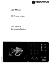
The RAMP RATE adjustment is for control over the combined times of acceleration
and deceleration.
The SYMMETRY potentiometer provides for control of the
accel6r~tion
frame.
for
time verses the deceleration time within the established total time
Acceleration and deceleration are near linear speed/time relatio~ships
most
applications.
stopping but
In
an application
hinders starting, acceleration
where
frictional
time is greater
loads
assists
than deceleration
time. The SYMMETRY adjustment should be made to provide less slope (more time)
for acceleration than for deceleration. See FIGURE 13.3.1.
P325 Operating Manual (Rev 1190)
Page 20
""z
D
u
w
(/)
'-.
>
w
Ck
Accelero. tion
Slope
Decelera tlon
Slope
. MAXIMUM SPEED
BASE SPEED
SECONDS
=
RAMP RATE
ta + tel
SYMMETRY
= to. VERSES tel
-··;-
FIGURE //13 . 3
13.4
VCO Specifications
The P325V has the same general specifications as the standard P325
driver, see SECTION 11, with the additional specifications listed below.
Series
Ramp rate: 50 to l control ratio
5 second max. acceleration time
100 rnsec min. acceleration time
TTL LOGIC INPUTS:
.·
STOP/RUN
·*
*
TTL
ACCEL
LOGIC OUTPUTS:
' ··
On a "High" signal the motor is stopped.
On a "Lawn signal the motor runs at the BASE SPEED.
On a
11
High 11 signal the motor is decelerated.
On a "Low 11 signal the motor is accelerated.
The logic outputs can drive one low power TTL
maximum capacitance of 15 picofarads.
*
AT SPEED indicator - goes "Low" when at MAXIMUM SPEED
*
CLOCK OUT indicator - goes "Low" for each motor step
P325 Operating Manual (Rev 1190)
Page 21
load with a
14
API Motor Listing
APPENDIX A
P325
PACKAGES
STATIC
TORQUE
(Oz. In.)
P325-A231A
WIDTH/
LENGTH
(Inch.)
2.3/2.0
*Bifilar
RATED
VOLTAGE **DIP SWITCH CONTROLS DIV.
CUR...'U:NT
MOTOR
TAP
#2
[ 123456 78]
(Amus /uh)
PART NUMBER
1.0
3
00001
A231-02A
P325-Ml71
15
1.7/1.3
1.7
2
01000
Mlll-03
P325-Ml72
20
l. 7/1.8
2.1
2
01100
Ml72-04
P325-M231
55
2.3/2.0
1.0
3
00001
M231-02
P325-M232
90
2.3/3.3
1.8
2
01001
M232-04
P325-M233
120
2.3/4.0
2.9
2
10100
M233-06
P325-M341
150
3.4/1.9
3.0
2
10101
~!341-
P325-M342
300
3.4/3.7
4.0
2
11111
M342-08
P325-M343
400
3.4/5.3
3.5
2
11010
M343-07
P325-M421
600
4.2/4.9
3.5
3
11010
M421-32
P325-M422
800
4.2/7.0
3. 8.
3
11101
M422-08
* -
See Section
8 for an
explanation of motor connections.
06
Current switch
settings for all the P325 series drives.
**
A •tO" indicates that
is "ON".
*** -
the switch is
11
0FF 11 and a
11
1 11 indicates the s\vitch
(See APPENDIX B for microstep resolution switch settings.
Linear Acctuator Model. Force is 100 lbs. for the packaged model that
includes a .050 inch lead screw (20 pitch). Other lead screw pitches are
available upon request.
Motors supplied with these packages come with the following:
->
Size 17 motors are 12 inch leads in an 8 lead configuration with a single
ended shaft.
Size 23 and 34 motors may be supplied with the following features:
->
->
->
Dual-shafted with a flat on the front shaft extension for positive load
coupling.
Designed to accept a 1000 line Dual Channel Incremental Optical Encoder
feature with Z channel home reference.
With 8 leads in twisted pairs in a six (6) foot shielded cable.
Size 42 motors may be supplied with the following features:
->
->
->
Dual-shafted with a flat/woodriff key on the front shaft extension for
positive load coupling.
Designed to accept a 1000 line Dual Channel Incremental Optical Encoder
feature with Z channel horne reference.
With 8 leads in twisted pairs in a six (6) foot shielded cable.
P325 Operating Manual (Rev 1190)
Page 22
15
APPENDIX B
Dip Switch Settings
Current Settings
Amps per
Phase
Switch (NOTE l),(NOTE 2)
Block //2
12345678
1.6
0.8
0.4
0.2
0.1
10000
01000
00100
00010
00001
NOTE 1 -
See DIAGRAM 8.1.3 for location of Switch Block #2.
A "0 ll indicates that
switch is 11 0N 11 •
NOTE ·2
the switch is "OFF" and a
"1" indicates the
The nominal current is 0.9 amps/phase with switches 1 - 5 on block
#2 turned OFF. Drive output current is the sum of switches l - 5
plus 0.9 amps/phase.
Microstep Resolution
Steps per
Revolution
Switch (NOTE 1)
Block //1
12345678
Switch (NOTE 2)
Block //2
12345678
-
200
400
800
1600
3200
6400
12800
25000
25600
NOTE 1
1110
1110
1110
1110
1110
1110
1110
(NOTE 4)
1110
!t->~ ~·.
Switch (NOTE 3)
Block //3
12345678
'
000
001
010
011
100
101
110
111
111
11111111
01111111
00111111
00011111
00001111
00000111
00000011
11000001
00000001
See DIAGRAM 8.1.3 for location of Switch Block #1.
A "0 11 indicates that the switch is "OFF" and a 11 1 11 indicates the
switch is "ON 11 •
Switches 1 - 4 are only utilized with the
velocity control oscillator option (P325V).
NOTE 2 -
See DIAGRAM 8.1.3 for location of Switch Block #2.
A "0" indicates that the switch is
switch is 11 0N 11 •
NOTE 3 -
See DIAGRAM 8.1.3 for location of Switch Block #3.
A 11 0 11 indicates that the switch is
switch is "ON".
NOTE 4 -
"OFF 11 and a "1" indicates the
Selectable current
profile settings
"0FF 11 and a "1 11 indicates the
are available
for specific
frame size motors when utilizing a microstep resolution of 25,000
steps per revolution.
P325 Operating Manual (Rev 1190)
Page 23
Profile Settings (25,000 Steps per Revolution Only)
Step Motor
Frame Size
M171-03
M172-04
M231-02
M232-04
M233-06
M341-06
M342-08
M343-07
M421- 32
M422-08
NOTE 1 -
Switch (NOTE 1)
Block.lf1
12345678
Switch (NOTE 2)
Block #2
12345678
:6§~6~111
0100
0100
0100
1000
0010
0001
0101
1001
1001
1001
See DIAGRAM 8.1.3 for location of Switch Block #1.
"OFF" and a
11
1" indicates the
See DIAGRAM 8 .1. 3 for location of Switch Block ff2.
A "0 11 indicates that the switch is
switch is "ON".
NOTE 3 -
11000001
11000001
11000001
11000001
11000001
11000001
11000001
11000001
11000001
11000001
00001111
00001111
01001111
10100111
10101111
11111111
11010111
110W111
11101111
A "0 11 indicates that the switch is
switch i"s 11 0N".
NOTE 2 -
Switch (NOTE 3)
Block #3
12345678
"0FF 11 and a "1 11 indicates the
See DIAGRAM 8.1.3 for location of Switch Block #3.
A "0 11 indicates that the switch is
switch is "ON 11 •
CLOSED 'ON'
"OFF" and a
11
1 11 indicates the
OPEN 'OFF'
S\./ITCH SETTINGS
P325 Operating Manual (Rev 1190)
Page 24
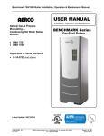
16
APPENDIX c
Performance Curves
4.50
!20
,.
SIZE23
"0
M34.3
lOU
M2:l3
100
'
\~)0
90
~
N
z
ao
,.:.,
0
'0
0
.,j
60
'0:>"'
3>-
:::>
0
a:
0
so
10
JO
JOO
250
200
!.'iO
100
20
so
10
0
0
0
60
40
20
0
8
12
SPEED·RPS
SPEED-RPS
aoo
SIZE 4.2
700
z
'0"'
uj
:::>
a
'E
500
500
400
-100
200
100
0
0
2
10
12
ld
'6
18
20
SPEED-RPS
[RPS -Revolutions Per Second)
Pullout curves generated utilizing 115VAC 1nput. 3200 steps per
revolution, and the SAC-560 Smart Axis Controller to provide
ramping routines and step pulses.
MOTOR SELECTIONS/DIMENSIONS
Static
Motor
P325-A231
P325-M171
P325·M172
P325-M173
P325-M231
P325-M232
P325-M233
P325-M34:
P325-M342
P325-M343
P325-M421
P325-M422
16
Torque
(Oz.-ln.)
15
20
25
=::
l[;
Width
Length
2.23" (57mm;
2.00" (51mm)
1.34" (34mm)
i 70" (42mm,
1_70" (42mm)
1 70" (42mm)
2.23" (57mml
2.23" (57mrn;
'211
2.23'' ,_lj7:Tl;nj
. :)l/
3.35 · ;86mmy
3.35·' i85mml
3.35" (85mmi
4.20" ( 106mm 1
4.20" (106mm]
300
400
600
aoo
1.54" (39mmi
1.84" (47mm)
2.00" (51mm)
3.25" (83mm)
4.00" (102mm)
2.45" (62mml
3.70" (93mm)
5.31" (135mm)
4.74" (120mm)
7.00" (178mm)
·' • Linear Ar.cuator model. Force is 40-100 !bs
P325 Operating Manual (Rev 1190)
Page 25
20
28
APPENDIX F
Optional 25 pin D Logic Connector (P325·DO-DB25)
l.(+)STEP and 14.(-)STEP: These inputs are optically isolated and driven by
producing a positive pulse to the (+)STEP with respect to the (-)STEP. These
inputs may also be differentially driven.
The step pulse must have a minimum
of 200 nanosecond-pulse and a 40% - 60% duty cycle (2 MHz max pulse rate) .
2. (+)DIRECTION and 15. (-)DIRECTION: These inputs are optically isolated and
driven by producing a positive pulse to the (+)DIRECTION with respect to the
(·)DIRECTION. These inputs may also be differentially driven.
The direction
input must be stable for · at least 2 ms before the drive receives the first
pulse.
9.FAULT COLL.
and 2l.FAULT EMIT.: These
fault outputs work in
conjunction to
produce a fault signal if a fault condition arises.
The output transistor will
conduct when the drive
is
functioning properly.
The transistor will not
conduct when there is a fault condition.
The different fault conditions are
OVER CURRENT, OVER TEMPERATURE, or UNDER VOLTAGE
ll.(+)RESET and 23.(-)RESET: These inputs are optically isolated and driven by
producing a positive pulse to the (+) RESET with respect to the (·) RESET.
This
input allows you to reset the motor phase currents to
the power up
position.
It must be active for 100 ms to reset and must be inactive for 100
ms before the first step pulse is received.
16.(+)SHUTDOWN and 17.(-)SHUTDOWN: These inputs are optically isolated and
driven by producing a positive pulse to the (+) SHUTDOWN with respect to the
(-) SHUTDOWN. This input can only be enabled when the motor is not moving.
It
must be active
for 100 ms to shutdown
the first step pulse is received.
and must be inactive for
100 ms before
18.(-)LOW PWR. and 19.(+)LOW PWR.: These inputs are optically isolated and
driven by producing a positive pulse to the (+) LOW PWR. with respect to the
(-) LOW PWR .. This input allows you to take the motor to low power to reduce
heat.
It must be active for 100 rns to go into low power and must be inactive
for lOO.rns before the first step pulse is received.
P325 User Guide
r-""-v[ ,
HCPL2631
274
~
_.,
-·~
1N6263
0
7
-
5
f
40 =f~
'<CeC">'>
3
--
f_£
..
i"
-
()--1·
0-
~+) STEP
<·~~ DIRECTIOI\1
F'"AUL T COLL.
11. ~+) RESET
14. ~-> STEP
15. <-> DrRECTION
16. ~-~> SHUTDO'WN
17. (-) SHUTDO\./N
18. C-> LEI\./ P\./R
19. ( ... ) LO\./ P\./R
21. F'AUL T EMIT.
23.<-) RESET
1.
2.
9,
J.V
1~
.U tr"<
SHUTDOWN+
0
~·ott--~-:~r~o-~-:~.
1'97
~
~
ll
LO\./ PO\./ER
F'AUL T
g;j
f.
HcPL 253 0 .
,
1
I.
o-1-,;f- FAULT OUTPUT CDLL
'9
---,-·~
5
2
-
-~
--t -
L___~
~
§..
7
D_UTPUT EMIT
_____12/t ~lKf
~~e===tLfOGVi:~P£0:\./E.~R~+========~~
C
l._ill-L..-E.Q_VE:B
274
HllA2
DE25
<F"EMALD
'''~J""
~-""
i
E xterno.I--/--In+.e-rno.l +.o [),-:ve
_[.L
§.
II
41_)(.
I
I
I
112
HllB!
'
HCP 25~[~0•
~----r--J
-~
-¥4
"'v"',
-
25 F' IN CONNECTOR l/0 SCHEMA TIC
·-·--
- - - - - ,_,
.3
-- _,-•
-~l_j
----- -L.---·--·· !5"'
8
AMERICAN PRECISION 1:\ot:STRIES
CONTROLS DIVISION
4401 Genesee Street
Buffalo, New York 14225
716-631-9800
FAX
716-631-0152