1
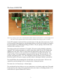
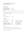
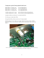
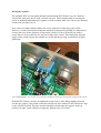
Oakley Sound Systems
5U Oakley Modular Series
EFG & EFG-Deluxe
Envelope Follower & Gate Extractor
PCB Issue 6
Builder’s Guide
V6.0.2
Tony Allgood B.Eng PGCE
Oakley Sound Systems
CARLISLE
United Kingdom
Introduction
This is the Project Builder's Guide for the issue 6 EFG and EFG-Deluxe modules from Oakley
Sound.
This document contains a full parts list for the components needed to populate the board and
gives details on how to wire up the module in either of its guises.
For the User Manual, which contains an overview of the operation of the unit, please visit the
main project webpage at:
http://www.oakleysound.com/follower.htm
For general information regarding where to get parts and suggested part numbers please see
our useful Parts Guide at the project webpage or http://www.oakleysound.com/parts.pdf.
For general information on how to build our modules, including circuit board population,
mounting front panel components and making up board interconnects please see our generic
Construction Guide at the project webpage or http://www.oakleysound.com/construct.pdf.
2
The Issue 6 EFG PCB
This is the prototype of the issue 6 standard EFG module behind a natural finish 1U wide Schaeffer panel.
Note the use of the optional Sock4 socket board to facilitate the wiring up of the six sockets.
On the EFG printed circuit board I have provided space for the four main control pots. If you
use the specified 16mm Alpha pots and matching brackets, the PCB can be held very firmly to
the panel without any additional mounting procedures. The pot spacing on this board is the
standard Oakley spacing of 1.625”.
The design requires plus and minus 15V supplies. The power supply should be adequately
regulated. The current consumption is around +48mA and -38mA for the EFG-Deluxe and
slightly less for the EFG. Power is routed onto the main PCB by either a four way 0.156”
MTA156 type connector or the special five way Synthesizers.com MTA100 header. You
could, of course, wire up the board by soldering on wires directly. The four pins are +15V,
ground, earth/panel ground, -15V. The earth/panel connection allows you to connect the
metal front panel to the power supply’s ground without it sharing the modules’ ground line.
The main PCB has four mounting holes for M3 bolts, one near each corner. These are not
required for panel mounting if you are using the three 16mm pot brackets.
The board size is 107mm (deep) x 143mm (high).
The main board has been laid out to accept connection to our Sock4 socket board. This small
board speeds up the wiring of the sockets and reduces the chances of building mistakes. Two
such boards are required with the EFG-Deluxe.
3
Issue 6 EFG and EFG-Deluxe Parts Lists
For general information regarding where to get parts and suggested part numbers please see
our useful Parts Guide at the project web page or http://www.oakleysound.com/parts.pdf.
The module may be built as one of two variants. There are significant differences between the
two builds. To make things easier I have provided two sets of parts lists, one for the EFG and
one for the EFG-Deluxe. Take careful note of the various links fitted to the board as not
getting this right will lead to much confusion.
In the parts lists the components are grouped into types and then values. The order of the
component names, R1, C1, etc. is of no particular consequence.
A quick note on European part descriptions. R is shorthand for ohm. K is shorthand for kiloohm. R is shorthand for ohm. So 22R is 22 ohm, 1K5 is 1,500 ohms or 1.5 kilohms. For
capacitors: 1uF = one microfarad = 1000nF = one thousand nanofarad.
To prevent loss of the small ‘.’ as the decimal point, a convention of inserting the unit in its
place is used. eg. 4R7 is a 4.7 ohm, 4K7 is a 4700 ohm resistor, 6n8 is a 6.8 nF capacitor.
A close up of the lower part of the EFG standard version showing two of the three links. You can see the
links in pins 2 and 3 of LK2, and pins 7 and 8 of I/O_2.
4
1. EFG Parts List
Resistors
1% 0.25W metal film types are to be recommended simply because they are better quality and
lower noise components. However, 5% ones can be substituted in most of the places if you
wish. The 3M3 resistors will probably have to be a 5% type since getting hold of a 1% metal
film resistor in this value is not trivial nor worthwhile in this case.
10R
22R
75R
100R
150R
510R
820R
1K
1K5
1K8
2K
3K
4K7
7K5
10K
12K
15K
18K
20K
22K
27K
30K
39K
47K
100K
220K
470K
1M
3M3
R25, R21
R37, R38, R33, R35
R59, R17
R29
R18, R7
R41, R54, R44, R57
R22
R31, R28, R4
R9
R10
R5, R23
R19
R8
R74, R73
R39, R1, R27
R20
R30
R3, R16
R6
R46
R26
R55, R40, R42, R53, R56, R45, R43, R58
R12
R61, R60, R72
R13, R63, R62, R36, R70, R47, R14, R71, R2, R64,
R49, R48, R50
R11
R24, R32
R34
R15
Capacitors
22pF C0G 2.5mm ceramic
100pF COG 2.5mm ceramic
560pF* C0G 2.5mm ceramic
680pF C0G 2.5mm ceramic
10nF polyester film box
C4, C14
C5, C38, C15
C40, C26, C41, C27
C30, C37, C31, C36
C8
5
100nF multilayer axial ceramic
680nF polyester film box
1uF polyester film box
2u2, 63V electrolytic
22uF, 35V electrolytic
47uF, 35V electrolytic
C32, C35, C33, C47, C9, C34, C46
C17, C28
C18, C19, C1, C24
C39, C29
C21, C22, C10, C11, C16, C6, C7
C3, C13, C25, C12, C20, C2
* 470pF may be used in place of 560pF.
Potentiometers (Pots)
Pots Alpha 16mm PCB mounted types:
47K or 50K linear
10K dual (stereo) linear
FREQUENCY, THRESHOLD, RESPONSE
GAIN
Three 16mm pot brackets.
LEDs
5mm red round LED
5mm orange round LED
5mm green round LED
PEAK
ENV
GATE
Three LED clips for front panel and three LED securing rings if required.
If using my suggested way of wiring up the LEDs you will also need three two way 0.1”
Molex style housings and six crimps.
Discrete Semiconductors
1N4148 signal diode
1N5819 Schottky power diode
BC550 NPN small signal transistor
BC560 PNP small signal transistor
D1, D2, D3, D4, D5, D6, D7, D8, D9, D12, D13
D18, D19
Q1, Q2, Q4, Q5
Q3
Integrated Circuits
OP275* dual audio op-amp
SSM2164 or V2164 quad VCA
TL074 quad FET op-amp
U1, U2
U5
U3, U4, U6
DIL IC sockets are to be recommended. You need two 8-pin, three 14-pin and one 16-pin
sockets.
6
* For the pre-amplifier any good dual op-amp can be used. Decent enough performance can
be had even with a TL072 or LF412.
Switches
SPST or SPDT toggle switch
X10
Miscellaneous
Leaded axial ferrite beads
L1, L2, L3
MTA156 4 way header
MTA100 6-way header
PSU
PWR
– Oakley/MOTM power supply
– Synthesizers.com power supply
Molex/MTA 0.1” header 6-way
Molex/MTA 0.1” housing 6-way
I/O_1
I/O_1
– for connecting to sockets
– for connecting to sockets
Wire Links
These are made either from resistor lead clippings or thin solid core wire.
1. LK is linked. LK is found between R24 and R33.
2. On LK2 use a single link to connect pins 2 and 3 together. Pins 1 and 4 have nothing
inserted.
3. On I/O_2 pins 7 and 8 are linked.
Components required if using the optional Sock4 board
Molex/MTA 0.1” header 8-way
Molex/MTA 0.1” housing 8-way
I/O on Sock4
I/O on Sock 4
112APC Switchcraft 1/4” socket
SK1, SK2, SK3, SK4 on Sock 4
L1 and L2 are left open and no links are fitted to the Sock4 PCB.
If using Molex KK you'll also need at least 32 crimp terminals.
Suitable lengths of wire to make up one single 100mm interconnect. 180mm of thin screened
audio cable. A single cable tie may be needed. See later for details.
7
2. EFG-Deluxe Parts List
Resistors
1% 0.25W metal film types are to be recommended simply because they are better quality and
lower noise components. However, 5% ones can be substituted in most of the places if you
wish. The 3M3 resistors will probably have to be a 5% type since getting hold of a 1% metal
film resistor in this value is not trivial nor worthwhile in this case.
10R
22R
75R
100R
150R
510R
820R
1K
1K5
1K8
2K
3K
4K7
7K5
10K
12K
15K
18K
20K
22K
27K
30K
39K
47K
100K
220K
470K
1M
3M3
R25, R21
R37, R38, R33, R35
R52, R59, R17
R29
R18, R7
R41, R54, R44, R57
R22
R31, R28, R4
R9
R10
R5, R23
R19
R67, R68, R8
R74, R73
R51, R39, R1, R27
R20
R30
R3, R16
R6
R65, R46
R26
R55, R40, R42, R53, R56, R45, R43, R58
R12
R61, R60, R72
R13, R63, R62, R36, R70, R69, R47, R14, R71, R2,
R64, R49, R48, R50
R11
R24, R32
R34
R66, R15
Capacitors
22pF C0G 2.5mm ceramic
100pF COG 2.5mm ceramic
560pF* C0G 2.5mm ceramic
680pF C0G 2.5mm ceramic
10nF polyester film box
C4, C14, C42
C5, C38, C15
C40, C26, C41, C27
C30, C37, C31, C36
C8
8
100nF multilayer axial ceramic
680nF polyester film box
1uF polyester film box
2u2 polyester film box**
2u2, 63V electrolytic
22uF, 35V electrolytic
47uF, 35V electrolytic
C32, C35, C33, C47, C9, C34, C46
C17, C28
C18, C19, C1, C24
C43, C45
C39, C29
C21, C22, C10, C11, C16, C6, C7
C3, C13, C25, C12, C20, C2
* 470pF may be used in place of 560pF.
** C23 and C44 are normally left empty when using 2.2uF capacitors in positions C43 and
C45. However, 2.2uF is quite a large value and you may not be able to obtain it from your
supplier. In this case simply use four 1uF polyester film caps in positions C23, C43, C44, C45.
Should you wish to achieve longer lag times you may wish to populate all four positions with
2u2 polyester box capacitors. This will double the rise and fall times of the lag generator in
both the minimum and maximum positions of the up and down pots.
Potentiometers (Pots)
Pots Alpha 16mm PCB mounted types:
47K or 50K linear
10K dual (stereo) linear
FREQUENCY, THRESHOLD, RESPONSE
GAIN
Pots Alpha 16mm PCB or chassis mounting types:
1M log
UP, DOWN – both mounted off board via flying wires.
Three 16mm pot brackets.
LEDs
5mm red round LED
5mm orange round LED
5mm green round LED
PEAK
ENV
GATE
Three LED clips for front panel and three LED securing rings if required.
If using my suggested way of wiring up the LEDs you will also need three two way 0.1”
Molex style housings and six crimps.
Discrete Semiconductors
1N4148 signal diode
1N5819 Schottky power diode
D1, D2, D3, D4, D5, D6, D7, D8, D9, D12, D13
D18, D19
9
BAT42 small signal Schottky diode D10, D11
BC550 NPN small signal transistor Q1, Q2, Q4, Q5
BC560 PNP small signal transistor Q3
Integrated Circuits
LF412 dual FET op-amp
OP275* dual audio op-amp
SSM2164 or V2164 quad VCA
TL074 quad FET op-amp
U7
U1, U2
U5
U3, U4, U6
DIL IC sockets are to be recommended. You need three 8-pin, three 14-pin and one 16-pin
sockets.
* For the pre-amplifier any good dual op-amp can be used. Decent enough performance can
be had even with a TL072 or LF412.
Switches
SPST or SPDT toggle switch
X10, EXP
Miscellaneous
Leaded axial ferrite beads
L1, L2, L3
MTA156 4 way header
MTA100 6-way header
PSU
PWR
– Oakley/MOTM power supply
– Synthesizers.com power supply
Molex/MTA 0.1” header 6-way
Molex/MTA 0.1” housing 6-way
Molex/MTA 0.1” header 8-way
Molex/MTA 0.1” housing 8-way
I/O_1
I/O_1
I/O_2
I/O_2
– for connecting to sockets
– for connecting to sockets
– for connecting to sockets
– for connecting to sockets
Wire Links
These are made either from resistor lead clippings or thin solid core wire.
On LK2 use two links to connect pins 1 and 2 together, and pins 3 and 4 together.
LK is left open and no links are fitted.
10
Components required if using optional Sock4 boards
Molex/MTA 0.1” header 8-way
Molex/MTA 0.1” housing 8-way
Molex/MTA 0.1” header 8-way
Molex/MTA 0.1” housing 8-way
I/O on left hand Sock4
I/O on left hand Sock 4
I/O on right hand Sock4
I/O on right hand Sock 4
112APC Switchcraft 1/4” socket
112APC Switchcraft 1/4” socket
SK1, SK2, SK3, SK4 on left hand Sock 4
SK1, SK2, SK3, SK4 on right hand Sock 4
A single wire link is to be fitted to L1 on both Sock4 PCBs.
L2 is left open on both Sock4 PCBs
If using Molex KK you'll also need at least 32 crimp terminals.
Suitable lengths of wire to make up one single 100mm interconnect and one 140mm
interconnect. Three or four cable ties. 180mm of thin screened audio cable. See later for
details.
All three LEDs can be wired in by using Molex KK 0.1” housings and solderless crimps. The LED clips
used here are the low profile types with white securing rings.
11
Connections
Power connections – MOTM and Oakley
The PSU power socket is 0.156” Molex/MTA 4-way header. Friction lock types are
recommended. This system is compatible with MOTM systems.
Power
Pin number
+15V
Module GND
Earth/PAN
-15V
1
2
3
4
Pin 1 on the I/O header has been provided to allow the ground tags of the jack sockets to be
connected to the powers supply ground without using the module’s 0V supply. Earth loops
cannot occur through patch leads this way, although screening is maintained. Of course, this
can only work if all your modules follow this principle.
Power connections – Synthesizers.com
The PWR power socket is to be fitted if you are using the module with a Synthesizers.com
system. In this case you should not fit the PSU header. The PWR header is a six way 0.1”
MTA, but with the pin that is in location 2 removed. In this way location 3 is actually pin 2 on
my schematic, location 4 is actually pin 5 and so on.
Power
Location number
Schematic Pin number
+15V
Missing Pin
+5V
Module GND
-15V
Not connected
1
2
3
4
5
6
1
2
3
4
5
+5V is not used on this module, so location 3 (pin 2) is not actually connected to anything on
the PCB.
If fitting the PWR header, you will also need to link out pins 2 and 3 of PSU. This connects
the panel ground with the module ground. Simply solder a solid wire hoop made from a
resistor lead clipping to join the middle two pads of PSU together.
12
Building the EFG module using the Sock4 board
This shows the Sock4 connection on a standard EFG. Here I have used Molex KK 0.1” connectors. These
are solderless crimp fixings that make a low cost but effective connection. Pin 7 and 8 of the interconnect
are connected via a screen cable (also crimped into the Sock4's Molex housing) and go on to the pre-amp
input, IN, on the main board.
Using the optional Sock4 boards is the simplest way of connecting all four, or eight, sockets
to the main board. The Sock4 board, or boards, should be populated in the way described in
our general construction guide found on the project webpage.
Neither wire link on the Sock4 is fitted when you are building the standard EFG module, but
L1 is fitted on both Sock4 boards when you are building the EFG-Deluxe.
For the standard EFG, and left hand Sock4 on the EFG-Deluxe, you now need to make up a
special interconnect and it's a little different than the usual eight way Sock4 interconnection
you may have done on other Oakley modules. The Sock4 features an eight way header but not
all eight connections are going back to the main board, and not all of those are going to the
same place on the main board. Pin 8 is carrying the pre-amp input and as such needs to travel
within a screened cable. The screen of that cable being connected to pin 7 of the Sock4
header. The other six connections of the Sock4's header can be connected to the I/O_1 header
on the main board but in truth only four (for the EFG) or five (for the EFG-Deluxe) of these
are actually used so we can save a bit of wire and only fit those.
13
Let's put those connections into a simple table to make it a little clearer:
Sock4 header
Main board destination
Pin 1
Pin 2
Pin 3
Pin 4
Pin 5
Pin 6
Pin 7
Pin 8
I/O_1 pin 1
I/O_1 pin 2
No connection
I/O_1 pin 4
I/O_1 pin 5 (not needed on standard EFG)
I/O_1 pin 6
Screened cable screen connects to IN pin 1
Screened cable core connects to IN pin 2
Remember that pin 1 is the square solder pad for any connector on an Oakley PCB. The
insulated wire needs to be around 100mm long and the screened cable around 180mm long.
The top end of the screened cable. The screen being connected to pin 1 and the core of the cable
connected to pin 2. Here I have used a bit of black heatshrink to keep things neat and tidy.
For the EFG-Deluxe you have two Sock4 boards. For the right hand board you simply need to
connect it to the main board's I/O_2 header with the usual eight way interconnect. Make this
interconnect from standard insulated multistrand wire. Its length should be around 140mm.
14
Hand wiring the sockets
If you have bought Switchcraft 112A sockets you will see that they have three connections.
One is the earth or ground tag. One is the signal tag which will be connected to the tip of the
jack plug when it is inserted. The third tag is the normalised tag, or NC (normally closed) tag.
The NC tag is internally connected to the signal tag when a jack is not connected. This
connection is automatically broken when you insert a jack.
Once fitted to the front panel the ground tags of each socket can be all connected together
with solid wire. I use 0.91mm diameter tinned copper wire for this job. It is nice and stiff, so
retains its shape. A single piece of insulated wire can then be used to connect those connected
earth tags to pin 1 of I/O_1 and/or I/O_2. Pin 1 is the square solder pad.
All the other connections are connected to the signal or NC lugs of the sockets. The tables
below show the connections you need to make:
1. Standard EFG
There are two headers that connect to the sockets, I/O_1 and IN. The IN header is near the
top of the board and carries the pre-amp input signal.
I/O_1
Pad name
Socket
Lug Type
Pin 1
Pin 2
Pin 3
Pin 4
Pin 5
Pin 6
PAN_GND
GATE
No connection
FLWOUT
No Connection
PRE_OUT
Connect to all sockets
GATE
Earth lugs
Signal lug
CV OUT
Signal lug
PRE OUT
Signal lug
IN
Pad name
Socket
Lug Type
Pin 1
Pin 2
GND
IN
PRE IN
PRE IN
NC lug
Signal lug
Use screened cable for connection from IN to PRE IN socket. Screen should connect to pin 1
and NC lug of PRE IN socket.
15
2. EFG-Deluxe
There are three headers that connect to the sockets, I/O_1, I/O_2 and IN. The IN header is
near the top of the board and carries the pre-amp input signal.
I/O_1
Pad name
Socket
Lug Type
Pin 1
Pin 2
Pin 3
Pin 4
Pin 5
Pin 6
PAN_GND
GATE
No connection
FLWIN
PRE_OUT
PRE_OUT
Connect to upper sockets
GATE
Earth lugs
Signal Lug
FOLLOW IN
FOLLOW IN
PRE OUT
Signal lug
NC lug
Signal lug
IN
Pad name
Socket
Lug Type
Pin 1
Pin 2
GND
IN
PRE IN
PRE IN
NC lug
Signal lug
Use screened cable for connection from IN to PRE IN socket. Screen should connect to pin 1
and NC lug of PRE IN socket.
I/O_2
Pad name
Socket
Lug Type
Pin 1
Pin 2
Pin 3
Pin 4
Pin 5
Pin 6
Pin 7
Pin 8
PAN_GND
LAG_OUT
No connection
LAG_IN
ABS_OUT
FLW/SLEW_OUT
ABS_OUT
SLEW_IN
Connect to lower sockets
LAG OUT
Earth lugs
Signal Lug
LAG IN
LAG IN
SLEW OUT
SLEW IN
SLEW IN
Signal lug
NC lug
Signal lug
NC lug
Signal lug
16
Wiring the switches
The standard EFG uses one panel mounted switch and the EFG-Deluxe uses two. Both are
wired in the same way, that is, with a twisted wire pair. This is simply made by twisting two
pieces of insulated multistrand wire together to form a simple cable. You can use two different
colours but you don't have to.
Now it does not matter which of those two wires connects to which lug on the switch.
However, to make the switches' behaviour match the front panel's legending it is important to
connect the wires to the right pair of lugs on the switch. For the x10 switch you need to
ensure the two wires connect to the top pair of lugs of the switch. This means that when the
toggle of the switch is down the contacts are closed and the pre-amp is switched to its high
gain mode.
The standard EFG's 'x10' switch. Note that the twisted pair connects to the top pair of lugs on the switch.
With the EFG-Deluxe you have an additional switch. Just to make things slightly awkward
you need to connect your switch so that the twisted wire pair connects to the bottom two lugs
on the LIN/EXP switch. Thus the contacts should be closed when the toggle is in the up
position. In other words it behaves in opposite fashion to the x10 switch.
17
Wiring the off board pots
The standard EFG has all of its pots mounted on the board. However, the EFG-Deluxe uses
two off board pots. These need to be connected to the main board with 'flying wires' much like
the switches. For my prototype I used twisted wire pairs again. This keeps most of the
unwanted stray noise from getting into the lag circuitry. However, the main board does allow
the use of twin cored screened cable for additional noise immunity if you wish to use that.
Each pot is wired identically with just two wires needed to make the connection. The pots are
used as variable resistors so we don't need to use all three of the pot's solder lugs. If you are
using twisted wire pairs you need to connect each pot as follows:
Pin 1 – the square pad
Pin 3 – the round pad
Wiper of the pot
CCW of the pot
The wiper of the pot is the middle pin. The CCW (counter clockwise) pin is the right hand pin
when the pot has it's pins facing down and you are looking from the rear. Remember the lag
circuitry produces its fastest times when the pot resistance is at its minimum value.
If you wish to use screened cable you need to ensure that the cable you are using has two
cores. This is sometimes called twin screened cable. Pin 2 of each of the pot's connecting pads
is connected to ground or 0V. Thus, for each length of screened cable, you can connect the
screen to pin 2. However, you must remember not to connect the screen at the other end of
the cable, the pot end, to anything. Just snip it off and use a bit of heatshrink to prevent the
frayed ends from shorting to anything they shouldn't.
18
Final Comments
If you have any problems with the module, an excellent source of support is the Oakley Sound
Forum at Muffwiggler.com. Paul Darlow and I are on this group, as well as many other users
and builders of Oakley modules.
If you can't get your project to work, then Oakley Sound Systems are able to offer a 'get you
working' service. If you wish to take up this service please e-mail me, Tony Allgood, at my
contact e-mail address found on the website. I can service either fully populated PCBs or
whole modules. You will be charged for all postage costs, any parts used and my time at
25GBP per hour. Most faults can be found and fixed within one hour, and I normally return
modules within a week. The minimum charge is 25GBP plus return postage costs.
If you have a comment about this builder's guide, or have a found a mistake in it, then please
do let me know. But please do not contact me or Paul Darlow directly with questions about
sourcing components or general fault finding. Honestly, we would love to help but we do not
have the time to help everyone individually by e-mail.
Last but not least, can I say a big thank you to all of you who helped and inspired me. Thanks
especially to all those nice people on the Synth-diy and Analogue Heaven mailing lists and at
Muffwiggler.com.
Tony Allgood at Oakley Sound
Cumbria, UK
© June 2011
No part of this document may be copied by whatever means without my permission.
19