1
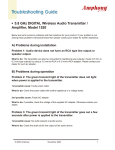
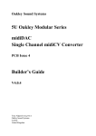
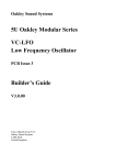
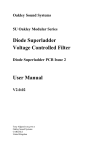
Oakley Sound Systems
Compact Power Supply
PCB Issue 1
User Manual
V1.2.0
Tony Allgood B.Eng PGCE
Oakley Sound Systems
CARLISLE
United Kingdom
1
Introduction
This is the User Manual for issue 1 of the Compact PSU circuit board from Oakley Sound.
The Compact PSU is a small footprint power supply unit with onboard regulators, heatsinks,
fuses and power distribution for Oakley and MOTM synthesisers. Current capacity depends on
the source of AC power that the unit runs from, but it has the potential to supply up to 400mA
on each power rail.
As well as giving details as to what the Compact PSU board does, this document contains
instructions on how to wire up your board to your source of power, any external switches and
the optional power indicators. We will also look at the Oakley power buss and how it differs
from the MOTM one yet retains complete compatibility with it. I will also give you some
information about suitable sources for your low voltage AC power supply.
The Oakley Compact PSU allows for various options in the installation. You can use the unit
either in full wave rectification mode for connection to tapped linelumps or twin secondaries,
or in half wave rectification for single phase AC output wallwarts and linelumps. If all this
sounds very confusing at the moment, do not worry, in this manual I will try to make it clearer
so that you make the right decision about what power supply you will need.
If you are building the Compact PSU as a complete DIY project please also download the
latest Builder's Guide. This can be found on the Compact PSU webpage along with our very
useful generic parts and construction guides.
Safety Warning
This supply has been designed to work with isolated low voltage AC inputs only. Connection
to any other supply is done at your own risk. Low voltage is classified as being less than 25V
with respect to the ground potential. Voltages above this level can, and often are, lethal to
living creatures.
Oakley Sound Systems will not advise on building or modifying this board to allow for direct
connection to the mains, or other high voltage sources, further to what is provided in this
document. Please do not ask us for additional information pertaining to direct mains
connections or using internally mounted transformers as we will not give it.
For safety and legal reasons we cannot recommend powering this board from any other
supply than low voltage AC output mains adapters.
Oakley Sound Systems are not liable for any damages caused by the misuse of this product. It
is your responsibility to use this product safely. If you have any doubt about installing a safe
power supply, then please do not attempt to do so.
2
The Oakley Compact PSU module
The power supply board will allow the conversion of a suitable low voltage alternating current
(AC) to be rectified, smoothed and regulated for operation with the Oakley Modular. The
module contains both the regulating devices, their heatsinks to keep them cool, and up to
seven 0.156” MTA headers for easy connection to your Oakley and other MOTM compatible
modules.
The voltage output of the module is a split rail 15V supply. This means it generates both +15V
and -15V. That is, two power rails, one of a positive voltage, the other a negative one. These
voltages are measured with respect to a common ground which is normally connected, via
your house's wiring, to the earth that you stand on. The voltage across both rails is 30V, with
the common ground sitting exactly in the middle of this at 0V.
The output current capability is the maximum current you can draw out of the power supply.
The current taken from the supply is determined by the amount of modules you are connecting
to the power supply. If you are using a single phase 500mA (or 0.5A) AC wallwart* then the
most current you can take from this power supply module is 125mA from each rail. That is,
take no more than 125mA from either the +15V supply or the -15V supply. Single phase
wallwarts are characterised by there only being two wires coming out of them.
Most Oakley modules take around 20 to 30mA each from both the +15V and the -15V rails.
That means you should restrict yourself to driving a maximum of six synthesiser modules in
your system. However, you must remember that some modules will take a lot more that
30mA, while some take a lot a less. Check with the module's User Manual or webpage to see
how much current each one takes.
Various companies make linelumps** with a greater capacity than 500mA. If you can get a
1A output one than this will be able to drive up to 250mA per rail.
Some linelumps, like the Yamaha one mentioned later in this document, use a split AC output
or a centre tapped AC output. This means it has three wires coming from it and will use a
different plug from the usual round barrel one you see on the single phase AC wallwarts.
Single phase mains adapters have only two wires coming from them so they can use a simpler
connecting plug.
The Oakley Compact PSU can be built with an optional full wave rectification ability. This
allows it to utilise split AC outputs very effectively. The recommended Yamaha 0.94A supply,
when used with the full wave rectification option on the Compact PSU module, can supply up
to 0.4A safely to both the +15V and the -15V rails. Taking currents over 0.5A (500mA) will
lead to very hot heatsinks and may damage the PA-20.
Two sets of screw terminal blocks are provided for connecting the low voltage AC power
source to the board and the optional power switch. If you are using a single phase wallwart to
power the PSU module than you need only to use two terminals per terminal block.
The board has four mounting holes for stable placement onto your modular case. Care should
be taken so that the board's various board mounted components do not come into contact with
3
any part of your modular's enclosure. One of the holes, the bottom right hand one, is
connected to the ground pins of the MTA headers via a resistor or wire link, R8. We will look
into this later on in the document.
The power supply has two integral fuse holders in case of a problem with the power supply
circuitry itself. Two fuses are needed if you are using full wave rectification, but only one, F2,
is required for ordinary half wave rectification. The fuse type should be a slow blow or antisurge type. The size is 20mm. It should be rated at between one and two times the maximum
current of your wallwart. Thus a 500mA AC output mains adapter should have a fuse that is
rated between 500mA and 1A, ideally 750mA. A 1A linelump should have a fuse that is
between 1A and 2A, ideally 1.5A.
Three on-board LEDs, one for +15V, one for -15V and one for the AC input, provide a quick
visual reference that all is well. All three LEDs could be fitted externally to the board and be
mounted on a front panel. However, the recommended way is to mount only the AC indicator
on the front of the synthesiser along with the AC power standby switch.
As we have seen the standard circuit provides two outputs, one at +15V and one at -15V.
Both output voltages can be finely adjusted with one trimmer. However, the unit can be very
easily modified to supply +/-12V if the need arises.
* A wallwart is the vernacular term for a low voltage mains adapter that plugs directly into the
wall. These take the form of a black plastic block that is shaped like an oversized mains plug.
Its called a wart simply because its appearance is somewhat uglier than a normal slimline plug.
** A linelump does the same job as a wallwart but it generally can handle greater currents.
Because of its increased size it cannot be made so that it will safely fit into a plug socket
directly. Thus the adapter sits in a black plastic box and connects to the wall via a cable and
traditional mains plug. It is therefore a black plastic lump connected to a line.
4
The Power Supply to the Power Supply
The standard method of powering the unit is from a low voltage tapped AC source. The safest
available option is to use a ready made 'wallwart' or ‘line lump’ supply.
You can use any 15V or 18V AC output wallwart of linelump you can source. The current
capability of the mains adapter, sometimes incorrectly called the 'ampage' will determine the
maximum current draw of your Compact PSU.
In the UK, the following types are recommended and have been tested to work with the
Compact PSU:
Maplin N57AT
This is a 7.5VA single phase AC output wallwart. It is a variable output type. This means it
has a little selector switch on the underside of the unit that allows you to change the output
voltage. You can select either 15V or 12V. Either voltage setting seems to produce enough
voltage for the Compact PSU to deliver +/-15V up to 125mA.
Because this is a single phase unit the compact PSU is wired in half-wave rectification mode.
You notice that only two wires come out of the wallwart and that you can select from a
variety of output socket types. Simply chose the one you would like to use on your system
and buy the appropriate socket for it to go into. I tend to recommend the 2.5mm DC power
plug one since this is the most common type of power socket.
You should fit fuse F2 only and it should be an anti-surge type and rated between 500mA and
1A.
Yamaha PA-20
This is a linelump supply and features a fixed 17.5-0-17.5 volt AC output at 0.94A maximum.
This means it gives us two AC outputs with a centre tap or mid point reference voltage. So
unlike the single phase AC adapter output with two leads, this one has three. This means you
need to use the Compact PSU in full wave rectification mode.
The PA-20 is made for Yamaha products and they are available from Yamaha spares
departments. You should ask for the power pack that goes with the MG12/4 mixer. These are
CE approved and connect to the mains via your local mains connector. They will be different
types depending on the country you need them for. It comes with a handy three way plug at
the low voltage end that you can use with an appropriate socket. If you wish you can ditch
their connector and use your own. Maplin sell a suitable three way connector to fit the
Yamaha one perfectly. Their part number is FM51F.
In the UK the line lump’s part number is V9812300 and the total cost is around £30 including
VAT and postage. We do have permission from Yamaha-Kemble in the UK to use this
particular part for the Oakley system, but in other countries this may be not so clear cut. The
liability issue once again rears its ugly head and they may not want to sell power items for
5
third party use. The best thing is to do is just to ask for a spare supply for your own MG12/4
mixer.
The Yamaha supply is rated at 0.94A. This means that by the time the output voltage has been
rectified and smoothed the actual current output should not exceed 0.52A. I have tested the
Compact PSU whilst drawing just more than this from both the +15V and -15V rails and the
two heatsinks get too hot to be safely used. So although it may be capable of driving this sort
of current for a very short period of time I would not recommend that the current exceeds
400mA per rail.
You should fit both fuses and both should be anti-surge types and rated between 1A and 2A.
The following device has not yet been tested but should work:
Maplin N58AT
This is a 1A single phase unit. It has the potential to deliver up to 250mA per rail when the
Compact PSU is used in half wave rectification mode.
If you have successfully used the Oakley PSU with any other types of power pack please do
let me know either directly or via the Oakley Sound forum at www.muffwiggler.com
6
Wiring Diagrams
Input wiring will depend on the type of wallwart or linelump you will be using.
Standard AC output wallwart
Single phase, two wire, wallwarts or linelumps need to use half wave rectification so the
Oakley Compact PSU can generate both positive and negative supplies simultaneously. They
only need the terminal's AC1 and 0V1 wired to the power socket. AC2 and 0V2 are left
unused.
Wallwart with single phase AC output, eg. Maplin N57AT
The front panel switch is a single pole single throw (SPST) switch which simply connects S1R
and S1S together when switched on. You can replace the switch with a simple wire link, but I
do recommend that a switch be fitted so the socket doesn't have to take the full surge current
when you insert it with the wallwart powered up.
I also recommend fitting the AC indicator LED too. This is so you know the wallwart or
linelump is on. The AC indicator is designed to indicate the status of incoming power and is
not determined by the position of the standby switch.
The standby switch should not be used to turn the unit off permanently. This should be done
by either switching the adapter off at the mains socket, or by pulling the adapter's plug out of
the mains socket.
An optional earth or grounding connection can be made. See later for more details.
7
Centre tapped wallwarts and linelumps
Centre tapped linelumps will have three wires coming from their connector. It will have two
AC outputs and one 0V. Take one of the AC outputs to terminal AC1 and the other AC
output to terminal AC2. It should not matter which AC output goes to AC1 or AC2. The 0V
should go to the 0V2 terminal.
Figure 2. Linelump wiring with centre tapped output, eg. Yamaha PA-20
The front panel switch is a double pole single throw (DPST) switch which connects S2R and
S2S together, and S1R and S1S together, when switched on. You can replace the switch with
two wire links, but I do recommend that a switch be fitted so the socket doesn't have to take
the full surge current when you insert it if the linelump is powered up.
I also recommend fitting the AC indicator LED too. This is so you know the linelump is on.
The AC indicator is designed to indicate the status of incoming power and is not determined
by the position of the standby switch.
The standby switch should not be used to turn the unit off permanently. This should be done
by either switching the adapter off at the mains socket, or by pulling the adapter's plug out of
the mains socket.
An optional earth or grounding connection can be made. See next section for more details.
8
Linelumps and Wallwarts: Fitting a Grounding Point
Using double insulated wallwarts and linelumps mean that you do not have to have a mains
safety earth fitted to your modular. However, if your modular is to talk to the rest of the
studio you need to make sure that the modular's ground is tied to earth somewhere in your
system. The most usual way of doing this is via the connecting cable's shield or screen
connection. Your mixing desk or monitoring equipment will be earthed and simply connecting
a cable to any module within your modular will tie the modular's ground to the other
equipment's earth. This seems pretty straightforward and it is so long as you have a small
system and only have one or two interconnecting cables in use.
However, a larger more complex system will have perhaps more than one modular, more than
one mixing desk and perhaps a heap of other outboard equipment. This is when it makes sense
to look at grounding your modular cases together.
Let us consider a more simpler scenario. Say we have built ourselves two modular cases and
we would like to connect the modules in them together to form an awesome monster patch.
Each case has its own PSU and each one is powered by a Yamaha PA-20. It is useful in this
situation to ensure that both PSUs are grounded together. In other words the two 0V lines
from each power supply should be firmly connected together. Although this will be done the
moment that one patch lead goes from one case to the other it is beneficial to do this with a
dedicated bonding wire.
We can do this in a variety of ways but one useful method involves having a 4mm banana
socket mounted near each power supply. The banana socket is connected to 0V on the PSU
board. The earth pad on the CPSU board provides a very handy point to connect the banana
socket. However, don't use the spare 0V1 or 0V2 terminals to connect the socket as the
PCB's copper tracks to these points can carry significant alternating current which could affect
the grounding. R8 and LK should both be fitted as wire links.
If both power supplies have a banana socket then it is a simple matter of patching the two
power supplies together with a banana patch lead. The nice thing about bananas is that they
are stackable so it's easy even if you have more than two PSUs to connect up.
I recommend that you use thick multistrand cable to make your grounding leads and that you
use good quality 4mm banana sockets and plugs.
9
Fitting an Internal Mains transformer
Be afraid, be very afraid...
Some of you old hands will laugh about the level of hysteria that surrounds direct mains
connection to DIY projects. However, this fear is more to do with our litigious society than
the real danger to the builder. Even so, I have had more than my fair share of high voltage
shocks over the years and it is not something I would want any builder to have to experience.
It has been purely luck that has saved me in several of those cases.
So I will say again – do not attempt to build a mains transformer into your modular case, or
any other project, without realising that to do so carries a risk of death to either you, or to the
person who may inadvertently put their fingers into your half built construction. Furthermore,
it is up to you as the builder of such an item to make sure, that once built, the item is safe to
use and meets all current safety legislation.
This is not a complete set of instructions on how to fit a transformer into a piece of
electronic equipment. This information is offered only as a guide and should not be
considered as your only source of information. No further information will be provided
by myself or Paul Darlow regarding the construction of mains powered items.
The mains transformer's secondaries should be rated:
18-0, 18-0 (or 18-0-18)
50VA
This will give you a power supply that should be seemingly capable of giving up to 0.8A on
each rail. However, due to heatsink size I would recommend that no more that 400mA be
taken from each rail. Taking any more than this will result is very hot heatsinks and possible
damage to the semiconductor devices. So if you do want to take more than this you should
consider either mounting the semiconductor devices on external heatsinks or using our other
more powerful power supply design.
Higher secondary voltages can be tolerated although you need to consider three things:
1. You may need a physically larger transformer for the same output power.
2. Your smoothing capacitors should be rated at a high enough working voltage to handle the
increased voltage across them.
3. The heatsinks will need to dissipate more energy because of the greater voltage drop across
the regulators. You may need to consider externally mounted heatsinks. A quick rule of thumb
is that if you can't touch the heatsinks for longer than ten seconds they are too hot.
In the wiring diagram I have included a suggested wiring method for connecting up a mains
transformer. Not all mains transformers are the same, some have additional windings, others
10
have tapped windings. I have simply used a single primary, double secondary type for example
only.
For the mains fuse you should use a 500mA anti-surge type. All wiring at mains potential
should be adequately insulated and protected from straying fingers.
There is no need to fit an AC standby switch since you will be fitting a proper mains power on
switch in series with the transformer primary coil. You will therefore need to link S1S to S1R,
and S2S to S2S.
Earthing
It is essential that everything you build, that has both live mains inside and a metal case or
panels, has a safety earth fitted. UK legislation says that any metal panelling should be
adequately insulated, ie. double insulated, or connected to earth. Since double insulating is not
practical in a home built enclosure, your metal case and any exposed metal parts should be
earthed.
Therefore all metal parts of your modular case should be bonded to earth via a thick piece of
wire back to the earth tang of the IEC power inlet or a common earth bonding point.
To ensure that the 0V of the power supply is also connected to earth, you should also connect
the 'earth' pad on the CPSU board to the earth tang of the IEC power inlet or the common
earth bonding point. It is worth noting that the bottom right hole on the CPSU board is
connected to the 'earth' pad, so you could use this as a connecting point instead. R8 and LK
should both be fitted as wire links.
However, this alone may not be sufficient for a solid safety earth bond. All panels should be
earthed directly either with their own direct connection to the earth tag on the power inlet, or
via the modular's earthed metal mounting rails and suitable toothed washer and screw. If you
have a wooden case with wooden mounting rails and you are toying with the idea of using a
mains transformer in your DIY power supply project then you may want to rethink your plans.
You will also need to provide earthing to any exposed transformer core.
It is possible that by earthing the front panel you may introduce earth loops when you connect
your mixer to the sockets of one of the modules. The outcome of this is audible humming at
50/60Hz and its harmonics. It is produced by earth currents travelling down the screen of the
connecting cable(s). This can be avoided by careful studio wiring and/or by using balanced
audio lines to pipe signals to and from the modular and mixing desk. Most mixing desks will
have balanced outputs and inputs.
11
Mains wiring diagram. For experienced builders only!
12
The Oakley Power Bus
In an ideal world I wanted the Oakley power bus to be based on a five way 0.156” MTA or
Molex connector. This would contain +15V, -15V and three grounds. One ground would be
the safety ground; this would be connected to the front panels and then directly onto the
main’s supply earth. The second would be a clean ground for all the analogue modules to take
their supply reference, the zero volt line, ie. 0V. The third would be a dirty ground. This
would be the ground reference for things like the noisy digital circuitry and LED switching.
However, this system would be incompatible with the MOTM modular which has a four way
connector for its analogue modules. So the question now remained, how could I make my
system work with MOTM, yet still retain some of the features I needed.
The chosen Oakley power bus comprises of +15V and -15V lines with two grounds. These
grounds are not connected together as in the MOTM. They are joined only at the power
supply in a wholly Oakley Modular.
In an Oakley modular one of the grounds, pin 2, goes straight to the power supply’s star
point. This is the analogue reference point and is correctly called 0V or module ground. This
is the same as the MOTM ground. The second ground is on pin 3. This is also connected to
the power supply’s ground. But this ground is connected only to the metal lugs of the sockets
on each module and nothing else on the module. It is this connection that sets the potential of
the patch lead’s screening and the metal case of the modular. This way it is impossible for
ground currents to travel down the inserted patch cords, since the panel is isolated from the
system ground except at one point.
However, this only works if ALL your modules follow this rule. If you insert just one MOTM
module into this system, the ‘benefits’ are lost. MOTM modules can be modified to allow full
Oakley compatibility although this should be done as you are building the module. Modifying
a completed MOTM module is possible, but the reverse side of the PCB must be accessed so
that you can cut the required tracks.
But I said earlier that the MOTM and Oakley power systems were compatible. And indeed
they are. Any Oakley module will work in a MOTM system. And vice versa. But you will not
get the inherent advantages of a two ground system if you mix and match systems.
Having said all that I have yet to hear any problems related to ground currents in any MOTM
or MOTM/Oakley systems.
One last thing, the LK link on the Compact PSU board joins the pin 2 ground with the pin 3
ground. By omitting LK you essentially isolate the pin 3 from the ordinary ground. There is
little reason for doing this in your modular, but I added it to allow anyone the option of using
the now floating pin 3 rail for something else.
13
Final Comments
I hope you that the Oakley Compact PSU lives up to your expectations and provides you with
a reliable source of power for your modular system.
If you have any questions about the module, an excellent source of support is the Oakley
Sound Forum at Muffwiggler.com. Paul Darlow and I are on this group, as well as many other
users and builders of Oakley modules.
If you have a comment about this user manual, or have a found a mistake in it, then please do
let me know.
Last but not least, can I say a big thank you to all of you who have helped and inspired me
over the years. Thanks especially to all those nice people on the Muff's forum and Synth-diy
and Analogue Heaven mailing lists.
Tony Allgood at Oakley Sound
Cumbria, UK
© September 2009 – updated December 2011
14