Download User manual TCO-7h Plus
Transcript
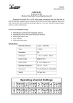
TCO-7h Plus
Wireless, 7-channel 5.8 GHz, external (IP65) Video/
Audio Transmitting-Receiving Kit for security cameras
systems
Registry number GIO E0012219W
5,8
7 25
mW
GHz
CHANNELS
FM
9 V DC
÷
14 V DC
-20ºC
÷
+55ºC
BNC UTP PAL IP65
VIDEO VIDEO NTSC
WARRANTY
24
MTHS
User’s Manual
Warranty conditions
Declaration of conformity
Contents
Product description . . . . . . . . . . . . . . . . . . . . . . . . . . . . . . . . . . . . . . . . . . . . . .
4
Contents of kit . . . . . . . . . . . . . . . . . . . . . . . . . . . . . . . . . . . . . . . . . . . . . . . . . . . .
4
Recommendations . . . . . . . . . . . . . . . . . . . . . . . . . . . . . . . . . . . . . . . . . . . . . . . . 5
Technical specification . . . . . . . . . . . . . . . . . . . . . . . . . . . . . . . . . . . . . . . . . .
6
Preparing set to work . . . . . . . . . . . . . . . . . . . . . . . . . . . . . . . . . . . . . . . . . . . .
6
RSSI connector - video signal strength measurement . . . . .
6
Operating channels setting . . . . . . . . . . . . . . . . . . . . . . . . . . . . . . . . . . . . .
7
Assembly . . . . . . . . . . . . . . . . . . . . . . . . . . . . . . . . . . . . . . . . . . . . . . . . . . . . . . . . . . .
7
Warranty general conditions . . . . . . . . . . . . . . . . . . . . . . . . . . . . . . . . . . .
9
Disposal of devices . . . . . . . . . . . . . . . . . . . . . . . . . . . . . . . . . . . . . . . . . . . . . . . 10
Product Features
Designed for wireless PAL or NTSC video signal transmission
over the radio-link on ISM 5.8 GHz band for surveillance
camera systems. Supports up to 7 channels within 5725 to
5875 MHz frequency band. Each of 7 channels has factory
defined operating frequency. It has one Video BNC input and
two audio input/output. Embedded anti-interference and
surge protection.
Contents of kit
Contents of TCO 5807h package:
1
2
3
ANTENNAS SIDE
4
1. Video/Audio transmitter with integrated antenna.
2. Video/Audio receiver with ipanel directional antenna.
3. Mounting bracket x 2 pcs.
4. User`s Manual.
5. Declaration of Conformity.
4
Recommendations
1. Larger monitoring systems consisting of several sets
should be set in sequence, i.e. the power connection of
next set should take place only after precise alignment of
the previous set.
2. Due to the generation of interference it is not recommended
to use switching power supplies other than those dedicated
by the manufacturer for example. ZS12 / 1A.
3. Recommended stabilized power supply, transformer 12V at
least 350mA.
4. It is recommended to install the receivers TCO-7h plus an
interval of at least 7 m from digital receivers (CDS-5021,
CDS-5IP, WI-FI antenna and others).
To ensure stable radio range, clear line of sight between the
antennas is a must. There should be 100% of optical visibility
in first Fresnel zone.
d - 3,9 m
D - 300 m
At a frequency of 5.8 GHz and 300 meters the radio beam
clearance of at least 3.9 m. should be provided
5
Specification
Operating frequency 5725 MHz–5875 MHz
Power
Receiver sensitivity
Impedancja
Modulation
Number of channels
Video format
Input
Audio Stereo
Audio band
Power supply
Operating temperature
Dimensions
Application
< 25mW; 14 dBm
- 85 dBM
50 Ω
FM
7 (chosen permanently)
PAL lub NTSC
BNC 1 Vp-p (75 Ω) + screw
connection UTP (100 Ω)
600 Ω, 2 Volt p-p
50–15000 Hz
9–14 V / 350 mA DC
from −20°C to 55°C
Tx: 80 × 130 × 75 mm
RX: 164 × 164 × 80 mm
outdoor IP65
Preparations for operation
Before mounting the unit on the mast you should:
-- Check whether the device has not been mechanically
damaged during transportation
-- Check the settings of the channel: transmitter and receiver
should be set to the same channel. If the settings are not
the same you should set it in accordance with the guidelines
set out in the table a) on page 7.
Connector RSSI - strength of the video signal
The receiver has the ability to connect an external radio signal
level meter TCO-Meter.
More: www.camsat.com.pl
6
Channel Setting
Table a) Channel settings
N
1
1
1
2
2
2
2
3
3
3
3
2
3
4
O
N
N
N
O
O
1
1
1
3
3
3
6
2
2
2
5
O
N
N
N
O
O
O
1
1
7
Assembly
1. Screw the bracket (triangle) to the base of unit
2. Attach the unit using the bracket to a stable mast.
3. Set the transmitter antenna directly at the receiving point.
(Note: the transmitter antenna needs to „see” optically with
receiver antenna - view from the antennas on the last page
of this manual).
4. Install the receiver and manage precisely the antenna
directly on the point of broadcasting.
5. Connect video signal cables and power supply as described
on the electronics board.
6. Set the desired operating channel according to the table
above. Channel numbers and antennas polarization
should be the same for both interacting with each other
transceiver devices. The transmitter assembly with
potentiometer VR enables to set the video level.
WARNING! This adjustment is necessary because of the
different levels of video cameras of different brands. The
regulation is also necessary when using passive converters
BNC / UTP.
The video signal should be connected to the In / Out BNC or
UTP connectors.
7
Terminals description:
GND – minus of the power supply and audio signal
A-L - Audio / left
A-R - audio / right
+12 V - plus DC
10-14 V minimum 350 mA
POWER LED
1 2 3
www.camsat.com
TRANSMITTER
CHANNEL
TCO-7h Plus Tx
CHANNELS
1
WIRELESS VIDEO & AUDIO
2
UTP VIDEO
+
UTP VIDEO
AUDIO
+ L GND R
CHANNEL
WIRELESS VIDEO & AUDIO
L
1
2
UTP VIDEO
+
SUPPLY
GND +12
CAMERA
POWER SUPPLY
8
www.camsat.com
RECEIVER
TCO-7h Plus Rx
3
3
4
L
5
AUDIO
GND R
6
7
SUPPLY
GND +12
RECORDER/
MONITOR
POWER SUPPLY
General terms and conditions of a warranty
Camsat company gives a warranty of 24 months for
transmission sets of the following series TCO-7H Plus.
1. In case of detecting incorrect work of a device, before
giving the device to the service, it is necessary to make
sure that everything was done in accordance with the
instruction manual.
2. In case of giving or sending the faulty device to be
repaired, it is indispensable to enclose a detailed
description in the written form including faulty action of
the device with taking into consideration work environment
and the way in which they can be seen.
3. One can use the warranty if he shows the proof of purchase
(a receipt) with the claimed device including the purchase
date and a description of the damage.
4. The warranty repair includes only damages resulting from
causes included in the sold device.
5. The warranty repair will be made in the shortest time
possible not exceeding 14 days counting from the date
of accepting the device to be repaired in the service. In
case of a necessity to import parts, the repair date can be
exceeded. After making the repair, the warranty period is
exceeded by the time of repair.
6. The guarantor is not responsible for losing configuration
settings of the device resulting from the repair of the
device or its damage.
7. The guarantor can refuse making the warranty repair or
completely renounce from the warranty in case of stating
that seals on the devices or subsystems included in it
are broken.
8. All remarks concerning the service and resulting
from the warranty are made only in the service of the
Camsat company.
9
The warranty does not cove
-- Mechanical damage and malfunctions caused by
random events such as fires, electrical surges, electrical
discharges, power, chemicals.
-- Damage caused by: incorrect use of the device, use of the
device for non-intended purpose or violating instruction
manual, customer negligence, improper operation
(temperature, humidity, flooding, dirt, sand inclusions,
improper power supply).
-- Claims due to technical parameters if they are in
accordance with the specified by the manufacturer.
-- The warranty does not cover the traces of use generated
during operation as scratches, dirt, wipe.
In matters not covered by the terms of this guarantee, the
relevant regulations of the Civil Code will be followed.
Disposal of devices
he adjacent symbol indicates that a particular
electrical and electronic equipment, after the end
of its service life must not be disposed of with
household waste. The device must be submitted to
designated collection points. For details of your
nearest collection point, please contact your local
authorities.
Proper disposal of this product allows you to save valuable
resources and prevent negative effects on health and the
environment which could be at risk in case of improper
handling of waste. Improper disposal of this waste provides
penalties in the relevant regulations.
10
DEKLARACJA ZGODNOŚCI
Niżej podpisany, reprezentujący firmę:
CAMSAT Przemysław Gralak
ul. Ogrodowa 2a 86-050 Solec Kujawski
niniejszym deklaruję z pełną odpowiedzialnością, że urządzenie
TCO-7h Plus jest dopuszczone do pracy na terenie EU i jest
zgodne z zasadniczymi wymaganiami oraz innymi stosownymi
postanowieniami dyrektywy 1999/5/WE.
Wymagania zasadnicze: Zastosowane normy
- artykuł dyrektywy
1999/5/WE
Oceniane
dokumenty
Ocena
Kompatybilność
Elektromagnetyczna –
art.3.1b
ETSI EN 301 489-1
V1.6.1
ETSI EN 301 489-3
V1.4.1
Sprawozdanie
z badań:
IŁ Nr 01500039/4
Zgodność
Efektywne wykorzystanie
Zasobów częstotliwości
– art.3.2
ETSI EN 300 440-1
V1.4.1
ETSI EN 300 440-2
V1.2.1
Sprawozdanie
z badań:
IŁ Nr 01500039/2
Zgodność
Zakres przestrajania częstotliwości nadajnika i odbiornika:
5725 MHz – 5875 MHz
Moc promieniowana nadajnika:
≤25,0 mW (14 dBm)
INSTYTUT ŁĄCZNOŚCI
ul. Szachowa 1, 04-894 Warszawa
Osoba odpowiedzialna:
Przemysław Gralak
Numer jednostki notyfikowanej:
1471
Stanowisko:
właściciel
Wydane przez Instytut Łączności
potwierdzenie zgodności nr
009/2009
Podpis:
oraz sprawozdania
z badań dostępne są do wglądu
w siedzibie firmy CAMSAT
Gralak Przemysław.
Solec Kujawski 01.07.2014
Manufacturer:
CAMSAT Gralak Przemysław
Ul. Ogrodowa 2a
86-050 Solec Kujawski
Offer and informations: www.camsat.com.pl
Service: service@camsat.com


